Baltic Ring – D2: Network Design Network architecture, technology and service selection for the Baltic Ring network Date: 02-09-2011 Author: Jani Myyry, CSC/Funet; Jari Miettinen, CSC/Funet; Tony Breach,
1 Executive Summary The current Baltic Ring networks are a patchwork of different network infrastructures ranging from advanced domestic and pan-north European Dense Wavelength-Division Multiplexing (DWDM) networks to managed third-party networks provided by commercial suppliers. In addition, more or less all international connectivity from Estonia, Latvia and Lithuania is provided by the GÉANT network, which again is based on a third-party managed service.
Looking ahead to the next five years, the Baltic Sea area has the challenge and opportunity to further improve the effectiveness of its service to the user community in many ways, especially in relation to a future-proof network infrastructure.
This document studies current resources and proposes a new Baltic Ring network infrastructure, based on the principle of federation, which supports all Baltic Sea countries.
The currently identified stakeholders in the Baltic Ring network are EENet (Estonia), SigmaNet (Latvia), LITNET (Lithuania), RUNNet (Russia) and NORDUnet (on behalf of the Nordic countries).
The starting point was to build only on currently available resources, in order to reduce costs, and to take into account user needs. These principles were then mapped to the elements of architecture planning work (namely, technology, topology, network operations and services).
Section 3 outlines the ultimate vision for the Baltic Ring network. It should aim to offer connectivity services to National Research and Education Networks (NRENs) by combining existing and new network equipment in the NRENs participating in the project. The network architecture should be a subset of lit dark fibre spans and managed network connections. The architecture should be future-proof, reliable, flexible, scalable and provide a sustainable carbon footprint without compromising cost efficiency.
The services delivered in the Baltic Ring network will have well-defined Service Level Agreements (SLAs) and will be combined with services from European and global partners to deliver end-to-end connectivity services across the globe. The Network Service Portfolio should include a packet and bit-transparent service and a remotely accessible IP service provided by a third-party NREN or service provider.
Section 4 studies the current Baltic Ring networks and services available from NREN resources, particularly in relation to the type of network and services offered, international services and interconnectivity, including the availability of Cross-Border Fibre (CBF) solutions, and the overall fibre footprint per country.
An important observation resulting from the study is that Estonia (EENet), Latvia (SigmaNet) and Lithuania (LITNET) do not have an advanced and agile DWDM infrastructure capable of supporting the architectural model proposed later in this report.
Section 5 provides a brief overview of technologies that could be used in building the Baltic Ring network. In addition, it presents an analysis of the current market situation. The technologies covered are: dark fibre, Reconfigurable Optical Add-Drop Multiplexer (ROADM), Optical Transport Network (OTN) and carrier Ethernet (cE). Section 5 does not describe in detail the technologies or the theory behind them. The focus is on how they can apply to the Baltic Ring network and service portfolio, including dynamic provisioning, protection and restoration.
Section 6 outlines the Baltic Ring network architecture options – a ring structure, which provides the necessary optical resiliency. In addition, two organisational frameworks are briefly discussed, both of which can be based on the same technological solution, leading to an architectural model based on a ring of interconnected agile DWDM networks with integrated OTN switching functionality. (The carrier-grade Ethernet switching layer on top of that is not considered since it is optional.) The model leads in turn to a high-level requirements set defined for the Baltic Ring as follows:
• Complete dark fibre footprint forming a ring – no managed service.
• Agile DWDM infrastructure supporting 40 G and 100 G plus wavelength and optional 10 G wavelength.
• Provide at least one, preferably two flexible add-drop Points of Presence (PoPs) in each country in order to achieve resiliency and to support service restoration.
• The architectural design should support the possibility of transporting a wavelength without Optical-Electrical-Optical (OEO) regeneration from Helsinki to Hamburg.
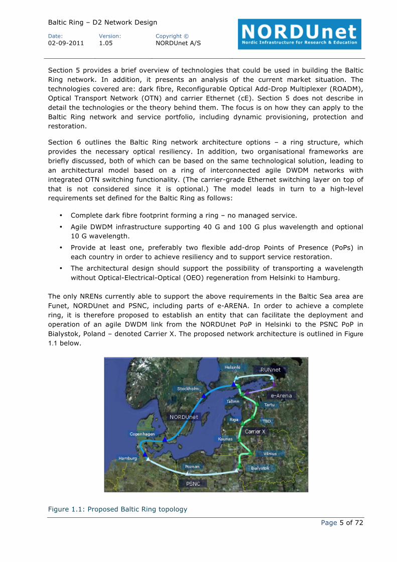
The only NRENs currently able to support the above requirements in the Baltic Sea area are Funet, NORDUnet and PSNC, including parts of e-ARENA. In order to achieve a complete ring, it is therefore proposed to establish an entity that can facilitate the deployment and operation of an agile DWDM link from the NORDUnet PoP in Helsinki to the PSNC PoP in Bialystok, Poland – denoted Carrier X. The proposed network architecture is outlined in Figure 1.1 below.
The link from Helsinki to Hamburg will be provided by NORDUnet and the link between Hamburg and Bialystok will be provided by PSNC. Carrier X, NORDUnet and PSNC will be the suppliers of an agile DWDM infrastructure forming a complete Baltic Ring.
In addition, e-ARENA would connect St Petersburg, Russia into the ring by constructing a new link between St Petersburg and Tallinn, Estonia. RUNNet’s current connection from St Petersburg to Helsinki would provide redundancy for the Russian NRENs. These proposals are also shown in Figure 1.1.
Hamburg will be the main gate for interconnection to GÉANT and other international partners; Helsinki and St Petersburg will be the main gates towards Russia and Asia.
The network service offering will be a bit-transparent service supporting 10 G, 40 G and 100 G network service interfaces of various programmable types:
• Ethernet. • OTN. • SDH (STM64 only).
Section 7 outlines the deployment budget for the Carrier X network segment (Helsinki, Finland to Bialystok, Poland including agile DWDM equipment and fibre footprint), excluding transponders:
• One year: 2.202.400 Euro. • Three years: 4.007.200 Euro. • Five years: 5.812.000 Euro.
The deployment budget for the e-Arena extension (from Tallinn, Estonia to St. Petersburg, Russia), including agile DWDM equipment and fibre footprint but excluding transponders, is:
• One year: 641.400 Euro. • Three years: 1.184.200 Euro. • Five years: 1.727.000 Euro.
The cost per bit-transparent 10 G, 40 G or 100 G channel through NORDUnet and PSNC will have to be negotiated between the future Baltic Ring Consortium, NORDUnet and PSNC.
2 Introduction The requirements of research and education (R&E) continue to evolve. The basic mission of engineering and operating an advanced networking infrastructure is no longer sufficient to satisfy the current and emerging needs of this dynamic community. Indeed, the NREN user base itself is no longer simply research and higher education, but is growing to include a broader social and cultural constituency.
To secure the support of the future NREN community, the NREN organisations must recognise these rapidly changing requirements, venture into new services and activities, and engage with other essential related organisations.
A modern networking infrastructure is one of the key components of the four-tiered e-Infrastructure needed to support the future requirements of e-Science and e-Education:
• Authentication and Authorisation Infrastructure (AAI). • Computing. • Networking. • Storage and data curation.
All “e-Projects” will be built on at least one of these pillars, but the use of them with regard to relative size and importance and to technical framework will vary from project to project.
The Baltic, Nordic and north European countries around the Baltic Sea could, in the near future, form a Baltic Ring network which could be a vital part of northern Europe’s solution to fulfilling this expanded mission. The Baltic Ring should be implemented in a technology-agnostic and transparent way, utilising existing resources and, where required to bridge any gaps, new resources, combined in a federated manner. The lowest common denominator of the Baltic Ring must equal or exceed what can be achieved from the normal commercial market. Whilst commercial services are available, these are usually offered only where there are significant profits to be made, whereas the Baltic Ring network should be able to deliver services throughout the Baltic Sea area, supporting R&E with a setup capable of providing flexible and efficient provision of services to a wide range of user communities.
The service categories should include (but not be limited to) the following:
The above service categories may each lead to more specific services. For example, two different Ethernet services could be constructed, one that offers point-to-point connections and one that offers multipoint-to-multipoint connections. The service used would be dependent on the actual use cases in the different NRENs participating in the ring. Similar examples may be outlined for all three service categories.
It is important to stress that the services offered to the users are dependent on the underlying network technologies. While the services defined are usually agnostic with regard to different technologies and network vendors, there is nonetheless a strong link to the underpinning networks. In order to optimise the benefits to the users in this particular project, this document describes the connectivity services and the underlying network technologies in separate chapters. Getting from the defined services to a defined network architecture is a matter of optimisation.
2.1 Opportunities for Improvement The current Baltic Ring networks are a patchwork of different network infrastructures ranging from advanced domestic and pan-north European DWDM networks to managed third-party networks provided by commercial suppliers. In addition, more or less all international connectivity from Estonia, Latvia and Lithuania is provided by the GÉANT network, which again is based on a third-party managed service.
Looking ahead to the next five years, the Baltic Sea area has the challenge and opportunity to further improve the effectiveness of its service to the user community in many ways, including:
• Extend and increase the robustness / resilience of the underlying fibre infrastructure. This requires a review of the fibre topology in the Baltic Sea area.
• Provide more flexible user connectivity. The future Baltic Ring network should facilitate alternative access points for NRENs, in order to make more efficient use of the infrastructure. This may lead to additional access points in a country or to shared access points between countries.
• Facilitate use of connectivity resources provided by NRENs. This is commonly known within the NREN community as cross-border fibre (CBF) (although this term is not technically accurate; the correct term would be managed third-party connectivity). Administrative and operational procedures are required to facilitate the use of these resources, which could contribute to reducing the overall cost of the Baltic Ring network.
• Support increasing demand in terms of bandwidth requirements. From traffic forecasts and what is currently understood of demands from scientific user communities and the NRENs in the Baltic Sea area, up to 100 Gbps aggregate capacities will be required in parts of the network either as IP, packet or Time-Division Multiplexing (TDM)-based services. This implies that the architecture needs to be flexible, to accommodate all types of requests efficiently.
• Ensure that the technology deployed is future-proof and state of the art, in order to deal with emerging requirements flexibly and efficiently. This challenge is made more difficult by the challenge to contain costs.
2.2 Architecture Planning Since December 2010 the project team has been conducting bilateral meetings with EENet (Estonia), SigmaNet (Latvia), LITNET (Lithuania), RUNNet (Russia) and NORDUnet (on behalf of the Nordic countries) in order to support and contribute to the planning of the Baltic Ring architecture [SigmaNet-meeting, LITNET-meeting, EENet-meeting, RUNNet-meeting].
The key principles that are driving the planning of the Baltic Ring architecture are:
• Use NREN resources. • Reduce costs. • Innovate. • Take user needs into account.
These principles have been mapped to the elements of architecture planning work, namely, technology, topology, network operations and services, as shown in Figure 2.1 below.
Figure 2.1: Baltic Ring architecture planning principles mapped to work elements
Considering their relative importance and whether a given aspect is adequately covered by the component networks already, the highest priority has been placed on:
• Developing a framework for the adoption of NREN connectivity resources (CBF). • Defining the service quality parameters for the service portfolio and how they affect
technology choices and network cost. • Examining the available technology options that can fulfil the Baltic Ring services and
meet the service quality levels defined, and their cost implications.
• Examining topology enhancements to resolve resilience issues and facilitate additional or alternative access points to the Baltic Ring network.
2.3 Approach to Baltic Ring Architecture Planning The approach to Baltic Ring architecture planning takes into account the following aspects:
• The contents of the Knowledge Infrastructure for the Fifth Freedom in the Baltic Sea Area [FFBSA], which summarises the project’s vision, strategic objectives and guiding
principles, and outlines the rationale for the Baltic Ring concept.
• The services offered to and required by the Baltic Sea area NRENs, how they are expected to develop, and what quality levels are associated with them.
• An analysis of the technological options that exist to fulfil those services,
complemented by an analysis of the availability and maturity of technology in the market.
• An analysis of the underlying fibre infrastructure and topology to ensure optimal
network reliability and performance at all levels, including a study of the availability of infrastructure to augment the Baltic Ring dark fibre footprint.
Each of these aspects is considered in detail in the deliverable.
To summarise, this deliverable provides a pre-study technical snapshot of the current research and education network situation in the Baltic Sea area, outlining feasible network technologies and structuring them as building blocks in order to propose a set of complete network architectures. In addition, the proposed solutions are supported by budgetary cost and resources estimates.
3 Vision The Baltic Ring network should aim to offer connectivity services to NRENs by combining existing and new network equipment in the NRENs participating in the project. The services delivered in the Baltic Ring network will be combined with services from European and global partners in order to deliver end-to-end connectivity services across the globe.
The connectivity services that are offered in the Baltic Ring network will also be extensible, thus local NRENs can inherit the service and modify/enhance its properties (network and management layer) as requested by local users. This extensible service offering means that the connectivity services offered by the Baltic Ring project should target a high Service Level Agreement (SLA) level. This in turn implies that services should be built on underlying components with well-defined SLA levels. For example, the underlying technical infrastructure (routers, switches, wavelengths, leased lines, fibres) must have an SLA that ensures the end-to-end SLA.
In the following subsection, a number of connectivity (network) services are described at a high level.
3.1 Network Service Portfolio The prospective Network Service Portfolio offered by the Baltic Ring network should encompass three main categories:
• IP service (Layer 3). • Packet service (Layer 2). • Bit-transparent service (Layer 1).
These service categories are described below in terms of what they provide to the users of the service. The descriptions do not cover how delivery of the service is technically engineered. For example, a Layer 2 transport service could be delivered using higher-level equipment like Multi-Protocol Label Switching (MPLS) (or Ethernet over MPLS (EoMPLS)) or on top of lower-layer equipment like SDH (or EoSDH). However, this is an optimisation process, that is, a process to deliver all requested connectivity services in the most optimum way (depending on optimisation goals).
3.1.1 IP Service The IP (Layer 3) service should offer NRENs access to the Nordic and European IP backbone allowing transit of IP traffic between Baltic, Nordic and European NRENs with further reach to associated networks globally.
The IP service should be designed so that it provides high availability figures for the users. This implies that the underlying technologies should use redundancy at some point. Downtime should be targeted to a few hours per year (or less) ideally. Furthermore, it should offer very low delays and delay variations for the IP packets carried, giving the users a high Quality of Experience (QoE) with the service. This implies that the network capacity is high enough to cope with user traffic even in peak hours.
IP peering services (i.e. services delivered by Internet Exchange operators) are not specified in this document.
The IP service should include:
• IPv4 (both unicast and multicast). • IPv6 (both unicast and multicast). • Layer 2 Virtual Private Networks (L2 VPNs).
3.1.1.1 L3 VPN Service
The Private Internet Service should offer an IP-based VPN (Virtual Private Network) service that allows research and education organisations in different NRENs to interconnect their local IP-based networks. This service is also commonly referred to as L3 VPN or MPLS VPN. It is also going to be specified and implemented as a part of the multi-domain service offering within the GÉANT project (GN3 [GN3]).
3.1.2 Packet Service The packet service delivers transport of user data between users of the service. The service has been divided into a number of subservices as described below.
3.1.2.1 Point-to-Point Services
Point-to-point services offer a path that enables transport of user data between two service demarcation points (client interfaces). The service is stitched between domains at Service Stitching Points. The service provides deterministic bandwidth, good throughput, low delay, jitter and loss, and high availability. These parameters may, of course, be waived at the user’s request. The point-to-point service may be transported by different underlying technologies that aren’t strictly Layer 2. For example, a Layer 2 service may be delivered on an EoMPLS technology platform.
Two different variants of the point-to-point service are described below. MEF (Metro Ethernet Forum) has defined a number of services within this field that can be used as a basis for this service category. The MEF services are Ethernet Private Line (EPL) and Ethernet Virtual Private Line (EVPL) within the E-Line category.
Dynamically Provisioned Point-to-point links may be provisioned by an automated system, thus making the lead time much shorter than for manually provisioned circuits. This feature is seen as a key requirement within specific user groups that want point-to-point connectivity with predictable, good throughput between changing end points.
Besides benefiting the user, there may be significant OPEX savings in this solution that far outweigh the CAPEX. A dynamically provisioned multi-domain service is currently under pilot trials in the GN3 project. Furthermore, there are considerable efforts to make this service global.
Manually Provisioned Manually provisioned point-to-point services offer the same features as described above, except that they typically require a much longer lead time due to the manual intervention with the equipment. The manual effort is further increased when dealing with multi-domain connections.
3.1.2.2 Multipoint-to-Multipoint Services
This service offers private LAN connectivity between different client locations. For example, a private office network may be offered this type of service. Two main definitions are specified by MEF, namely Ethernet Private LAN (EP-LAN) and Ethernet Virtual Private LAN (EVP-LAN) within the E-LAN category.
3.1.2.3 Rooted Multipoint Service
The rooted multipoint service offers traffic separation between end users, with traffic from one “leaf” being allowed to arrive at one or more “roots” but never being transmitted to other “leaves”. This type of service is targeted at traffic from mobile backhaul and triple play infrastructure like Passive Optical Networks (PONs). Within the MEF E-Tree service category, two services are defined, namely Ethernet Private Tree (EP-Tree) and Ethernet Virtual Private Tree (EVP-Tree).
3.1.2.4 Client Interface
The transport services described above can be delivered with different client interfaces. Flexibility with regard to client interfaces is desirable because of the different technologies used in NRENs connecting to the ring. Typical client interfaces are Ethernet, OTN and SDH.
3.1.3 Bit-Transparent Service A bit-transparent service should provide transparent 10 Gbps to 100 Gbps wavelengths between any two PoPs on the network or connected to the Nordic and European dark fibre cloud without the need for Reamplifying, Reshaping and Retiming (3R) regeneration and could, in principle, be extended to other world regions via dedicated transparent wavelength services provided by other international NRENs. In addition, the bit-transparent service should support:
• 10 Gbps to 100 Gbps wavelength connections, with the potential for smooth scaling to 400 Gbps+.
• Bit-transparent service adhering to common standards with client framing supporting packet and TDM standards, which should support interconnectivity to domestic network layers.
• Diversely routed backup circuits in order to provide resiliency in the case of a dark fibre outage.
3.1.4 Connectivity Services Summary In the subsections above, different services have been defined based on their main properties seen from the user’s point of view. The decision as to which of these services should be offered in the Baltic Ring should be based on an analysis of the traffic patterns expected in the ring and the need for traffic separation. Once this has been determined and the services have been shortlisted, a network design process should be started, accompanied by an RFI/RFQ process.
3.2 Network Architecture The network architecture vision for the Baltic Ring network is a subset of lit dark fibre spans and managed network connections. The architecture should be future-proof, reliable, flexible, scalable and provide a sustainable carbon footprint without compromising cost efficiency. The architecture should be seen as a totality covering Layers 1, 2 and 3, with convergence between layers where relevant.
The network topology should be combined ring structures consisting of lit dark fibre and managed network services. The “glue” between the rings should primarily be provided by Layer 1 solutions, which, in conjunction with Layer 2 and 3 solutions, would facilitate the multiplexing, switching and routing of traffic flows including add-drop of traffic to users or other domains.
The Layer 1 network-to-network interface (NNI) channel count should be greater than 72 and should include client traffic transparency; the rate should support from 10 Gbps to 100 Gbps. The system should be enabled for increasing capacity granularity, e.g. 400 Gbps and 1 Tbps, without the need for additional major hardware upgrade and without other technical limitations of the network solution. The solution should compensate for optical system impairments, including the dark fibre span impairments.
The Layer 1 and 2 user-to-network interface (UNI) should support most common types of traffic flows, such as Ethernet and OTN interfaces, with the option of handling legacy SDH interfaces (STM16, STM64). The traffic rate should have a granularity from 1 Gbps to 100 Gbps and should be upgradable for increasing capacity granularity to 400 Gbps and 1 Tbps.
The Layer 1 and 2 Optical-Optical-Optical (OOO) and OEO interworking area should support terabit carrier-class multiplexing and grooming. In addition, it should support ingress policing and egress shaping on packet traffic flows.
The Layer 2 and 3 solution should be carrier class with flexible client-interface support up to at least 100 Gbps. UNI interfaces should have deep packet buffers suitable for supporting high-performance wide-area data transfers and oversubscription. The NNI interfaces should have the potential for a smooth integration into the underlying transmission, limiting the need for additional OEO conversion.
The Layer 2 and 3 solutions should as a minimum support most common types of IP operation protocols, i.e. IPv4 and IPv6, including virtualised operation and routers. The number of routes in the Forwarding Information Base (FIB) should be greater than 1 million. In addition, the solution should have a scalable solution for establishing common L2 and L3 services.
The overall solution should have a standardised generalised control plane for any type of traffic, providing automated network and service provisioning. The control plane should provide vertical integration across layers, leading to seamless operation. In addition, it should have carrier-class Operation, Administration and Maintenance (OAM) capabilities very similar to SDH and support in-service software upgrades with minimal operational impact.
3.3 Network Operation The management system should be a Fault, Configuration, Accounting, Performance, Security (FCAPS) system, should manage all network elements and contain a network planning tool. The network management system should have open northbound and southbound interfaces. The management system should support event correlation, and service provisioning and activation, including the possibility of dynamic provisioning in combination with control plane protocols and resource applications. In addition, it should support automatic device and logical topology discovery.
The management solution should ideally be built on a lightweight hardware configuration with built-in resiliency for all process and hardware components.
4 The Current Baltic Ring Networks and Services The Baltic Ring is a multi-national structure which builds on the Baltic Sea area national research and education networks (NRENs). These networks, their resources and cross-border connections enable the Baltic Ring connectivity and hosting services on a large scale. The following sections describe the current NREN networks, and detail the resources required for the proposed new Baltic Ring that do not currently exist.
4.1.1 NORDUnet NORDUnet operates an Alcatel-Lucent DWDM network which covers the Scandinavian capitals (Stockholm, Oslo and Copenhagen), and has redundant connectivity to Finland (Espoo and Helsinki) and Germany (Hamburg). NORDUnet’s current DWDM network provides add-drop capabilities in all of those sites, and can offer capacity services for the Baltic Ring without any major technology or availability restrictions.
The most important NORDUnet add-drop sites, from the Baltic Ring point of view, are in Espoo, Helsinki and Hamburg. In Espoo, NORDUnet, Funet and RUNNet DWDM networks meet in the same premises and can be easily interconnected. Similarly, in Helsinki, NORDUnet and Funet are located close to each other. Espoo and Helsinki are also the closest NORDUnet sites with a cross-border fibre possibility to Tallinn, Estonia. In Hamburg, NORDUnet and PSNC are in the process of relocating to the same premises used by other NRENs.
NORDUnet can also offer colocation and operational services in collaboration with the Nordic national NRENs.
4.1.2 Funet Funet operates a Nokia Siemens Networks DWDM network which covers Finnish cities with higher education institutions. The Funet DWDM network has add-drop capabilities in around 25 sites in Finland. However, due to geographical coverage (the network extends to the north from Espoo and Helsinki), Funet’s connectivity services may not be perfectly suitable for the Baltic Ring. Instead, Funet can offer colocation and operational services in Espoo and Helsinki.
There is no existing cross-border connectivity between Espoo or Helsinki, Finland and Tallinn, Estonia. Due to the Gulf of Finland between Finland and Estonia, a submarine fibre connection or capacity service is required.
4.1.3 EENet EENet’s DWDM network connects Tallinn, the Estonian capital, and Tartu, where EENet is headquartered. In addition, EENet has leased-capacity links to other cities in Estonia. EENet can offer colocation and hosting services.
There is no existing cross-border connectivity between Tartu, Estonia and Riga, Latvia. A major road and railway connection exists between the cities. Another option would be a link between Tallinn and Riga routed near the Baltic Sea coast. A fibre or an additional capacity service is required to connect Estonia and Latvia.
As between Estonia and Latvia, there is no current cross-border connectivity between Tallinn, Estonia and St Petersburg, Russia. A fibre or an additional capacity service is required.
4.1.4 SigmaNet Similarly to EENet, the current network of SigmaNet, the Latvian NREN, is based on leased capacity. SigmaNet has its main site in Riga and offers services to other cities in Latvia. There is a submarine fibre connection from Ventpils, Latvia to Stockholm, Sweden, which is used by a university for research purposes. SigmaNet can offer colocation and operational services in a major point of presence in Riga where most of the Latvian operators have their equipment and fibre connections.
Between Latvia and Lithuania there are multiple fibre connectivity routes which could be used for cross-border connectivity: Riga–Siauliai and Riga–Vilnius. A fibre or an additional connectivity service is required. Cross-border connectivity to Estonia is described in the EENet section (Section 4.1.3).
4.1.5 LITNET LITNET, the Lithuanian NREN, has a ring structure DWDM network covering five cities. The ring consists of two parts. The southern section between Vilnius, Kaunas and Klaipeda builds on Transmode equipment. The more recent northern part, between Klaipeda, Siauliai, Panevezys and Vilnius, has ADVA equipment. Lithuania has quite extensive access fibre availability throughout the country due to the Development of Rural Area Information Technology Network (RAIN) fibre development project.
LITNET can offer connectivity services via its DWDM network in addition to colocation and operation services. However, there is currently limited channel availability in the DWDM network and the DWDM equipment may require upgrading. LITNET has its headquarters in Kaunas, Lithuania.
Between Lithuania and Poland there are multiple possible cross-border fibre connectivity routes. A route from Vilnius and two routes from Kaunas could be used to interconnect LITNET and Poland’s PSNC network. PSNC has a fibre connection to the Lithuanian border, though Bialystok is the nearest site to Lithuania that has a presence on the PSNC DWDM network. Lithuania and Latvia cross-border connectivity options are described in the SigmaNet section (Section 4.1.4).
4.1.6 PSNC PSNC operates an ADVA DWDM network, which reaches from Bialystok, Poland via Poznan, Poland to Hamburg, Germany. The PSNC DWDM network has no major technology restrictions and can offer connectivity services to the Baltic Ring. PSNC can also provide colocation and operational services.
The PSNC and NORDUnet networks could easily be interconnected in Hamburg as they will both have a DWDM add-drop site in the same premises. The span between Poland and Lithuania is already partially covered by an existing PSNC dark fibre from Bialystok to the Lithuanian border, though on the Lithuanian side of the border there are no existing fibres that can be used. The fibre route options in Lithuania are described in the LITNET section (Section 4.1.5).
4.1.7 RUNNet and e-ARENA RUNNet operates a Nortel DWDM network between St Petersburg, Russia and Espoo, Finland. The network is modern and has no technology restrictions. RUNNet can offer connectivity services via its DWDM network, in addition to colocation and operational services in St Petersburg.
The Russian NRENs, RUNNet and RBNET, operate under the National Association of Research and Educational e-Infrastructures (e-ARENA).
The cross-border fibre between St Petersburg and Tallinn, Estonia is described in the EENet section (Section 4.1.3).
4.2 Current Topology and Services The Baltic Ring connectivity, colocation, hosting and operational services can be partly provided today via existing services from the area’s NRENs. However, to realise the ring structure, the missing segments must be established and connected to each other. The main sections currently lacking any connectivity services are between the Poland/Lithuania border – southern Lithuania; northern Lithuania – Latvia; Latvia – southern Estonia; Estonia – Russia; and Estonia – Finland submarine link. There are also alternative possibilities for the Estonia – Finland submarine link.
The existing DWDM networks and missing segments of the ring are shown in Figure 4.1 with the Poland – Estonia segment highlighted in amber, the Estonia – Russia segment in green, and the submarine segments in blue.
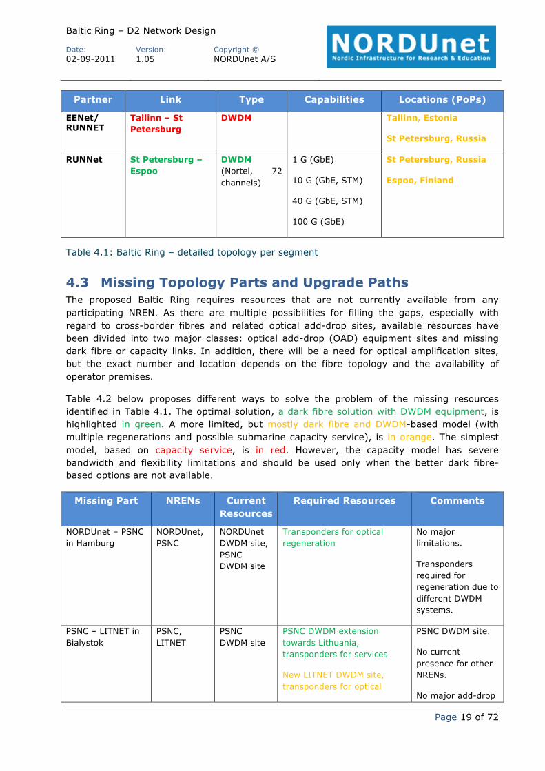
The network segments are detailed in Table 4.1 with missing connections or sites highlighted in red, existing connections or sites requiring upgrades in orange, and existing connections and sites requiring no upgrades in green.
Table 4.1: Baltic Ring – detailed topology per segment
4.3 Missing Topology Parts and Upgrade Paths The proposed Baltic Ring requires resources that are not currently available from any participating NREN. As there are multiple possibilities for filling the gaps, especially with regard to cross-border fibres and related optical add-drop sites, available resources have been divided into two major classes: optical add-drop (OAD) equipment sites and missing dark fibre or capacity links. In addition, there will be a need for optical amplification sites, but the exact number and location depends on the fibre topology and the availability of operator premises.
Table 4.2 below proposes different ways to solve the problem of the missing resources identified in Table 4.1. The optimal solution, a dark fibre solution with DWDM equipment, is highlighted in green. A more limited, but mostly dark fibre and DWDM-based model (with multiple regenerations and possible submarine capacity service), is in orange. The simplest model, based on capacity service, is in red. However, the capacity model has severe bandwidth and flexibility limitations and should be used only when the better dark fibre-based options are not available.
Missing Part NRENs Current Resources
Required Resources Comments
NORDUnet – PSNC in Hamburg
NORDUnet, PSNC
NORDUnet DWDM site, PSNC DWDM site
Transponders for optical regeneration
No major limitations.
Transponders required for regeneration due to different DWDM systems.
PSNC – LITNET in Bialystok
PSNC, LITNET
PSNC DWDM site
PSNC DWDM extension towards Lithuania, transponders for services
New IP router to terminate capacity service from Lithuania and connect PSNC DWDM network
needs.
PSNC extension preferred due to technical capabilities.
PSNC – LITNET CBF or capacity link
PSNC, LITNET
Dark fibre on Polish side of border, none on Lithuanian side
Dark fibre link between Bialystok – Kaunas/Vilnius
Capacity service between Bialystok – Kaunas/Vilnius
PSNC has an existing dark fibre to the Lithunian border.
In Lithuania, multiple dark fibre providers and routes are available.
LITNET – PSNC in Kaunas or Vilnius, LITNET – SigmaNet in Klaipeda, Siauliai or Vilnius
LITNET, PSNC, SigmaNet
LITNET DWDM site
New PSNC DWDM site, new DWDM site towards Latvia, interoperation without regeneration, transponders for services, IP router for BoD and IP services
LITNET DWDM system extension towards Poland, new DWDM site towards Latvia, transponders for regeneration and services, IP router for BoD and IP services
New IP router to terminate capacity service from Poland and to provide BoD and IP services
LITNET’s northern part and PSNC’s DWDM systems are from the same vendor. LITNET’s current system has channel limitations. Regeneration may not be needed.
Kaunas and Vilnius are important add-drop sites for LITNET.
IP/MPLS router required for BoD and IP services.
LITNET DWDM network from Kaunas or Vilnius to Klaipeda, Siauliai
LITNET LITNET DWDM network
DWDM channel extensions for all required paths
Limited DWDM channel extensions
Capacity service over DWDM system
LITNET has a DWDM network on top of the dark fibre ring.
LITNET DWDM network has limited channel availability without channel extensions.
LITNET – SigmaNet CBF or
LITNET, SigmaNet
None Dark fibre link between Klaipeda, Siauliai or Vilnius –
Capacity service between Klaipeda, Siauliai or Vilnius – Riga
Multiple capacity service providers.
SigmaNet – LITNET in Riga
SigmaNet, LITNET
SigmaNet IP router site
New DWDM site towards Lithuania and Estonia, interoperation in both directions without regeneration, transponders for services, IP router for BoD and IP services
New DWDM site towards Estonia and Lithuania, no interoperation, transponders for regeneration and services, IP router for BoD and IP services
New IP router to terminate capacity service from Lithuania and Estonia, and to provide BoD and IP services
No DWDM systems in use, no restrictions from previous equipment.
Riga is a very important add-drop site for SigmaNet.
IP/MPLS router required for BoD and IP services.
SigmaNet – EENet CBF or capacity link
SigmaNet, EENet
None Dark fibre link between Riga – Tartu or Tallinn
Capacity service between Riga – Tartu or Tallinn
Incomplete info about dark fibre availability.
Capacity service available from multiple providers.
EENet – SigmaNet in Tartu or Tallinn
EENet, SigmaNet
EENet DWDM site
New DWDM site towards Latvia, new DWDM site towards Finland and Russia, transponders for regeneration and services, IP router for BoD and IP services
New DWDM site towards Latvia, new DWDM site towards Russia, transponders for regeneration, capacity service towards Finland, IP router for BoD and IP services
New IP router to terminate capacity service from Latvia,
EENet DWDM system between Tartu and Tallinn, channel restrictions.
Tallinn and Tartu are important add-drop sites for EENet.
New DWDM site towards Estonia, transponders for regeneration and services, IP router for BoD and IP services
New IP router to terminate capacity service from Estonia and DWDM path from Russia to provide BoD and IP services
(NORDUnet) is more important.
Espoo preferred due to RUNNet presence.
Connection to Estonia via dark fibre or capacity services.
Table 4.2: Baltic Ring – missing parts and upgrade options
4.4 Current Market Situation This section describes currently available dark fibre and other connectivity services. The information has been collected from NRENs and operators. The situation varies from country to country. Typically, however, capacity services are widely available compared to dark fibre. Dark fibre connections require a long-term commitment and, in some cases, direct investments to get a fibre built.
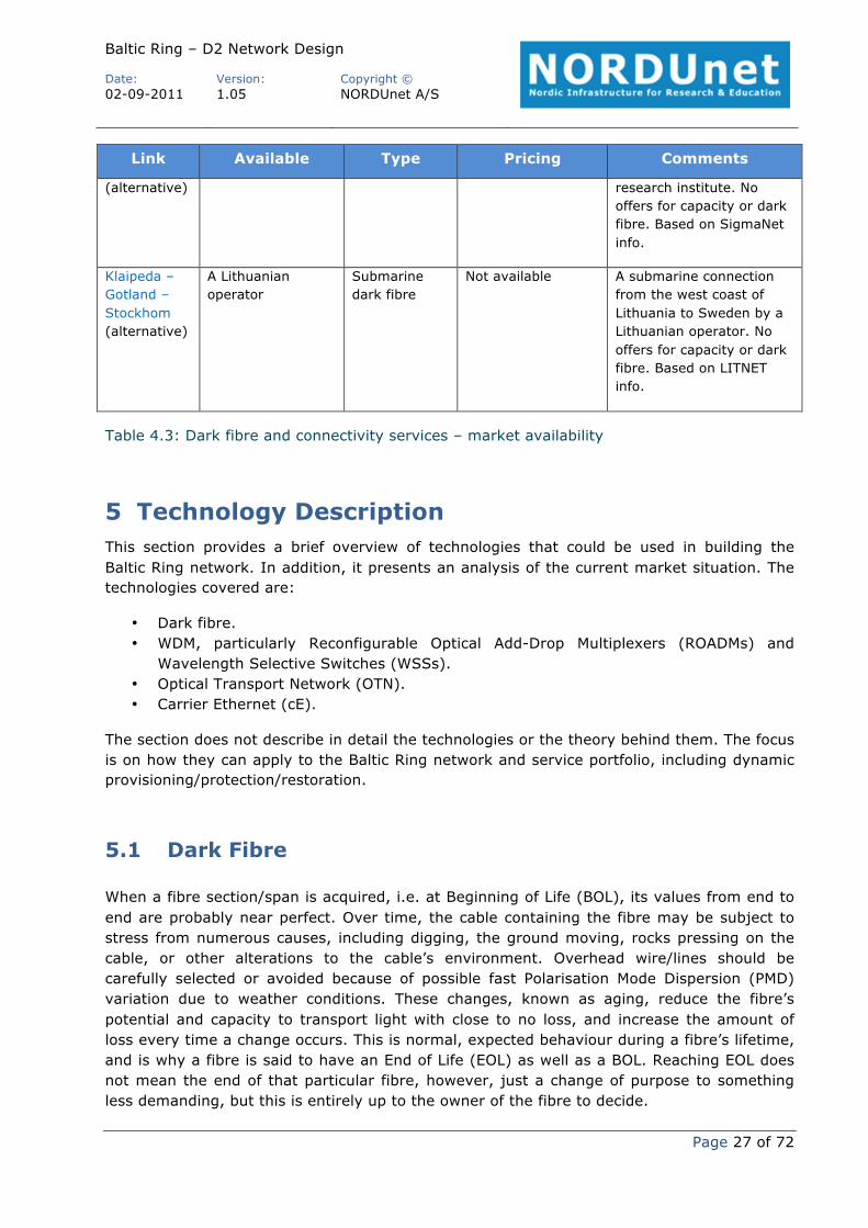
Table 4.3 summarises the current market availability of services from the Baltic Ring project point of view. The availability information is based on pre-inquiries without formal tender and without information about the scale of the network or the services needed. Dark fibre options may be available even though only capacity services have been offered. The most challenging connection is a submarine link between Estonia and Finland or, alternatively, between Estonia, Latvia or Lithuania and Sweden.
4.4.1 Lithuania (LITNET) • LITNET has an existing dark fibre ring around the country. • Dark fibre availability is quite good, competition exists. • The RAIN rural area fibre development project provides dark fibre connections to rural
and remote sites within Lithuania. • There are several possible dark fibre routes between Kaunas and Vilnius, Lithuania
and the Polish border, to which PIONIER already has dark fibre connectivity from Bialystok:
o Kaunas – Alytus – Lazdijai – Polish border. o Kaunas – Marijampole – Polish border. o Kaunas – Alytus (power company, secondary route). o Vilnius – Alytus (national railway company, tertiary route).
• There are multiple possible dark fibre routes from Lithuania to Riga, Latvia: o Klaipeda (via Palanga) to Liepada. o Siauliai to Riga.
Other possible routes are available, but connections to existing LITNET DWDM sites are preferred.
• Dark fibre pricing example: ~around 6500 Euro per month from Kaunas, Lithuania to the Polish border.
• Capacity services are available within Lithuania and to Latvia and Poland. • LITNET’s major sites are in Kaunas and Vilnius.
4.4.2 Latvia (SigmaNet) • A leased fibre from Ventpils, Latvia to Stockholm, Sweden which is used by a Latvian
institution for research purposes. • Capacity services are available within Latvia and to Estonia and Lithuania. • Major operator colocation site in Riga, Latvia, where SigmaNet also has presence. • A major road and railway connection between Riga and Tartu.
4.4.3 Estonia (EENet) • EENet has a dark fibre connection between Tallinn and Tartu. • Capacity services are available within Estonia and to Finland and Latvia. • A major road and railway connection between Tallinn and St Petersburg. • Dark fibre available to the Russian border (able to meet a possible Russian connection
at a power station near the border). • Submarine dark fibre available from Tallinn to Helsinki, Finland.
o Preliminary offer for a dark fibre pair. • Dark fibre availability in Estonia is quite new.
4.4.4 Finland (Funet) • Dark fibre available from multiple operators, also other (non-operator) dark fibre
providers. • Dark fibre price for longer spans is around 2,5 Euro per km per month. • Cross-border capacity from Helsinki and Espoo to Tallinn, Estonia available from 2
Finnish operators. No dark fibre was offered. • Submarine dark fibre available from Helsinki to Tallinn, Estonia.
o Preliminary offer for a dark fibre pair.
4.4.5 Russia (RUNNet) • Dark fibre within power lines from St Petersburg to Estonian border (able to meet a
possible Estonian connection at a power station near the border).
Link Available Type Pricing Comments
Espoo or Helsinki to other cities in Finland
Multiple dark -ibre operators
Dark fibre 300 Euro per km per year, multiple-year contract (Funet info)
Availability varies; usually multiple operators offer services. Pricing based on Funet DWDM network pricing for long spans.
Espoo or Dark fibre and Submarine 35000 Euro per Submarine dark fibre and
Two Finnish operators offered services: only capacity service, no submarine dark fibre offered.
A Baltic area capacity service operator.
Tallinn – St Petersburg
Power company dark fibre (Russia), operator dark fibre (Estonia)
Dark fibre Estonian side: 590 Euro per km per year (EEnet and Porta Optica info)
135000 Euro per year Estonian side, 110000 Euro per year Russian side (estimated, if pricing similar)
Dark fibre may be available via power company on the Russian side of the border (RUNNet info).
Tallinn – Tartu
EENet dark fibre
Capacity service operator A, B, C
Dark fibre, capacity
590 Euro per km per year (EEnet and Porta Optica info)
Dark fibre in existing service
145000 Euro per year
Two Finnish operators offered services: only capacity service, no submarine dark fibre available.
EENet dark fibre connection.
A Baltic area capacity service operator.
Tartu – Riga Capacity service operator A, C
Capacity Estonian side 590 Euro per km per year (EEnet and Porta Optica info), Latvian side 590 Euro per km per year (estimated, based on Estonian level)
45000 Euro per year Estonian side, 125000 Euro per year Latvian side
Dark fibre options based on EENet, SigmaNet and Porta Optica info.
One Finnish operator offered services: only capacity service, no dark fibre offered.
A Baltic area capacity service operator.
Riga – Klaipeda,
Multiple dark fibre Dark fibre, Latvian side 590 Euro per km per
(alternative) research institute. No offers for capacity or dark fibre. Based on SigmaNet info.
Klaipeda – Gotland – Stockhom (alternative)
A Lithuanian operator
Submarine dark fibre
Not available A submarine connection from the west coast of Lithuania to Sweden by a Lithuanian operator. No offers for capacity or dark fibre. Based on LITNET info.
Table 4.3: Dark fibre and connectivity services – market availability
5 Technology Description This section provides a brief overview of technologies that could be used in building the Baltic Ring network. In addition, it presents an analysis of the current market situation. The technologies covered are:
• Dark fibre. • WDM, particularly Reconfigurable Optical Add-Drop Multiplexers (ROADMs) and
The section does not describe in detail the technologies or the theory behind them. The focus is on how they can apply to the Baltic Ring network and service portfolio, including dynamic provisioning/protection/restoration.
5.1 Dark Fibre
When a fibre section/span is acquired, i.e. at Beginning of Life (BOL), its values from end to end are probably near perfect. Over time, the cable containing the fibre may be subject to stress from numerous causes, including digging, the ground moving, rocks pressing on the cable, or other alterations to the cable’s environment. Overhead wire/lines should be carefully selected or avoided because of possible fast Polarisation Mode Dispersion (PMD) variation due to weather conditions. These changes, known as aging, reduce the fibre’s potential and capacity to transport light with close to no loss, and increase the amount of loss every time a change occurs. This is normal, expected behaviour during a fibre’s lifetime, and is why a fibre is said to have an End of Life (EOL) as well as a BOL. Reaching EOL does not mean the end of that particular fibre, however, just a change of purpose to something less demanding, but this is entirely up to the owner of the fibre to decide.
An unwanted factor that also plays a role in the fibre’s lifetime is direct damage to the cable, in most cases a fibre cut. In such a case, the fibre needs to be repaired as soon as possible. To help find the location, in order to dig up the cable and splice the fibres together again, an Optical Time-Domain Reflectometer (OTDR) is used.
5.1.1 Dark Fibre Requirements In order to take technical and surrounding events into consideration, there are strict requirements for performing measurements.
For the Baltic Ring network, there is a requirement to keep loss, Polarisation Mode Dispersion (PMD) and Chromatic Dispersion (CD) levels as low as possible, to provide the best working conditions for the DWDM equipment using the fibre spans. The requirements for the fibre change when the equipment is upgraded to greater speeds or more bandwidth. This is why the Baltic Ring requires the fibres to be of the best quality, and why fibres should be spliced as opposed to patched wherever possible.
The requirements for spliced fibre should be interpreted from end-equipment site to end-equipment site, without exceptions.
5.1.2 Detailed Requirements The detailed requirements in Table 5.1 below are to be seen as an initial statement of requirements in a procurement scenario, which can be negotiated to reach the optimal cost benefit ratio for the Baltic Ring network.
Requirements are expressed as values for events and total loss per km.
The fibre connection of a span shall consist of an uninterrupted glass fibre end to end. If this requirement is impossible to fulfil, then every fibre span must be considered on a case-by-case basis.
All of the requirements must be met within the C-Band 1530–1570 nm wavelength spectrum unless stated otherwise.
Parameter Requirement
Age of optical fibre The optical fibre itself (not only the cable) shall have been manufactured after 1992.
ITU-T specification The dark fibre shall be specified according to ITU-T G.652 or ITU-T G.655. For ITU-T G.655 the True Wave Classic shall not be accepted. For each part of the infrastructure the same ITU recommendation shall be valid throughout that part.
Attenuation of a submerged span
The attenuation at 1550 nm should not exceed 23 dB and shall not exceed 35 dB.
Attenuation of other submerged spans
The attenuation at 1550 nm should not exceed 23 dB and shall not exceed 26 dB.
Attenuation and The attenuation of a dark fibre (DF) span at 1550 nm shall not
exceed 23 dB and the length should not exceed 80 km. This does not apply to passive submerged cables.
Additional specifications
The DF parameters of the installed cable shall, during the whole contract period, comply with the values in 1–7 below. The values include effects of possible future splicing, repair, aging, etc.
1. Attenuation at 1550 nm shall be less than 0.25 dB/km and should be less than 0.22 dB/km.
2. Bend losses shall not be accepted. 3. Seasonal variations in the fibre parameter shall not be
accepted. 4. Connector losses shall be less than 0.5 dB. 5. Reflection shall at any point be below -40 dB. 6. Chromatic Dispersion at 1550 nm (CMD 1550 nm) shall be
less than18.5 ps/nm/km. 7. Polarisation Mode Dispersion (PMDQ) shall be less than 0.50
ps/√km and should be less than 0.20 ps/√km.
Documentation The supplier shall provide documentation for each span in an electronic readable format stating:
1. Manufacturing date, manufacturer’s name and cable type. 2. Attenuation at 1310 nm and 1550 nm. 3. Bi-directional optical time-domain reflectometer (OTDR)
measurements at 1310 nm and 1550 nm 4. Physical map of each span of path.
If PMDQ exceeds 0.20 ps/√km then the supplier shall provide measurement reports or manufacturing data for each span in an electronic readable format stating the Polarisation Mode Dispersion (PMDQ) value.
Repairs 1. Each repair loss in each direction shall be less than 0.5 dB at 1550nm.
2. Bend losses shall not be accepted. 3. The supplier shall perform quality testing of repair after
damage. 4. After repair, the supplier shall produce a test report, in
original digital form, containing the following data: 5. Bi-directional OTDR measurement at both 1310 nm and
1550 nm with high resolution around the repaired location. 6. Attenuation at 1550 nm.
5.1.3 Cross-Border Dark Fibre If the Baltic Ring has access to NREN dark fibre, e.g. in a CBF scenario, the cross-border dark fibre that is provided by NRENs shall comply with the same requirements as stated above.
5.2 Wavelength-Division Multiplexing (WDM) Wavelength-Division Multiplexing (WDM) is a technology that multiplexes a number of optical carrier signals onto a single optical fibre by using different wavelengths (colours) of laser light. This technique enables bi-directional communications, typically over a single fibre, as well as multiplication of capacity.
A WDM system uses a multiplexer at the transmitter to join the signals together, and a de-multiplexer at the receiver to split them apart. With the right type of fibre it is possible to have a device that does both simultaneously, and can function as an optical add-drop multiplexer.
WDM systems can handle up to 160 signals and can thus expand a basic 10 Gbps system over a single fibre pair to over 1.6 Tbps.
WDM systems are divided into different wavelength patterns: conventional or coarse wavelength-division multiplexing (CWDM) and dense wavelength division multiplexing (DWDM).
Conventional WDM systems provide up to 8 channels in the third transmission window (C-Band) of silica fibres around 1550 nm.
CWDM, in contrast to conventional WDM and DWDM, uses increased channel spacing to allow less sophisticated and thus cheaper transceiver designs. To provide 8 channels on a single fibre, CWDM uses the entire frequency band between the second and third transmission window (1310 nm /1550 nm respectively).
DWDM uses the 1550 nm transmission window but with denser channel spacing. Channel plans vary, but a typical system would use 40 channels at 100 GHz spacing or 80 channels with 50 GHz spacing. Some technologies are capable of 25 GHz spacing.
The following subsections focus on DWDM systems, since these are the most relevant for the Baltic Ring network due to the amount of capacity they provide and the wavelength reach.
5.2.1 DWDM Systems
A basic DWDM system contains several main components, including:
These are described in the following sections. The section ends by considering transmission capacity and constraints, and service quality parameters.
5.2.1.1 DWDM Terminal Multiplexer
The terminal multiplexer contains one wavelength-converting transponder for each wavelength signal it will carry. The wavelength-converting transponders receive the input optical signal from a client-layer Ethernet, OTN, SDH or other signal, convert that signal into the electrical domain, and retransmit the signal using a 1550 nm band laser.
The terminal mux also contains an optical multiplexer, which takes the various 1550 nm band signals and places them onto a single fibre. The terminal multiplexer may or may not also support a local Erbium Doped Fibre Amplifier (EDFA) for power amplification of the multi-wavelength optical signal.
5.2.1.2 Intermediate Line Amplifier (ILA)
An Intermediate Line Amplifier (ILA) is placed approximately every 80–100 km for compensating the loss in optical power while the signal travels along the fibre. The signal is amplified by an EDFA, which usually consists of several amplifier stages.
5.2.1.3 Optical Supervisory Channel (OSC)
The Optical Supervisory Channel (OSC) is an additional wavelength usually outside the EDFA amplification band (at 1510 nm, 1620 nm, 1310 nm or another proprietary wavelength). The OSC carries information about the multi-wavelength optical signal as well as remote conditions at the optical terminal or EDFA site. It is also normally used for remote software upgrades and user (i.e. network operator) Network Management information.
Unlike the 1550 nm band client signal-carrying wavelengths, the OSC is always terminated at intermediate amplifier sites, where it receives local information before retransmission.
5.2.1.4 Pluggable and Software-Tunable Transceiver Modules
Recent innovations in DWDM transport systems include pluggable and software-tunable transceiver modules capable of operating on 40 or 80 channels. This dramatically reduces the need for discrete spare pluggable modules, when a handful of pluggable devices can handle the full range of wavelengths.
5.2.1.5 Wavelength Transponders
Transceivers versus Transponders Transceiver – Most practical communication systems require duplex communication requiring two wavelengths, typically one fibre for each direction (a fibre pair). As a result, at each end both a transmitter (to send a signal over a first wavelength) and a receiver (to receive a signal over a second wavelength) will be required. A combination of a transmitter and a receiver is called a transceiver. It converts an electrical signal to and from an optical signal.
Transponder – In practice, the signal inputs and outputs are optical, meaning that wavelength conversion (optical to electrical to optical (OEO)) is required. This is done by a transponder. A transponder can be made up of two transceivers placed after each other. The
first transceiver converts the optical signal to/from an electrical signal, and the second transceiver converts the electrical signal to/from an optical signal at the required wavelength.
Evolution of Wavelength-Converting Transponders Transponders originally served to translate the transmitted optical signal of a client-layer signal into one of the DWDM system's internal wavelengths in the 1550 nm band. Even external wavelengths (Alien Wavelengths) injected into the 1550 nm will most likely need to be translated, as they will almost certainly not have the required frequency stability tolerances nor will it have the optical power necessary for the system’s EDFA. That can to some degree be solved by using WSS-based ROADMs.
In the mid-1990s, however, wavelength converting transponders in back-to-back links rapidly took on the additional function of signal regeneration. Signal regeneration in transponders is typically re-time, re-transmit, re-shape (3R) or overhead-monitoring multi-bit-rate 3R regeneration.
3R transponders are fully digital and normally able to view SDH section layer overhead bytes such as A1 and A2 to determine signal quality health.
Multiplexed transponders (muxponders) essentially perform some relatively simple time division multiplexing of lower rate signals into a higher rate carrier within the system. A common example is the ability to accept 4 x STM16 then output a single STM-64 in the 1550 nm band.
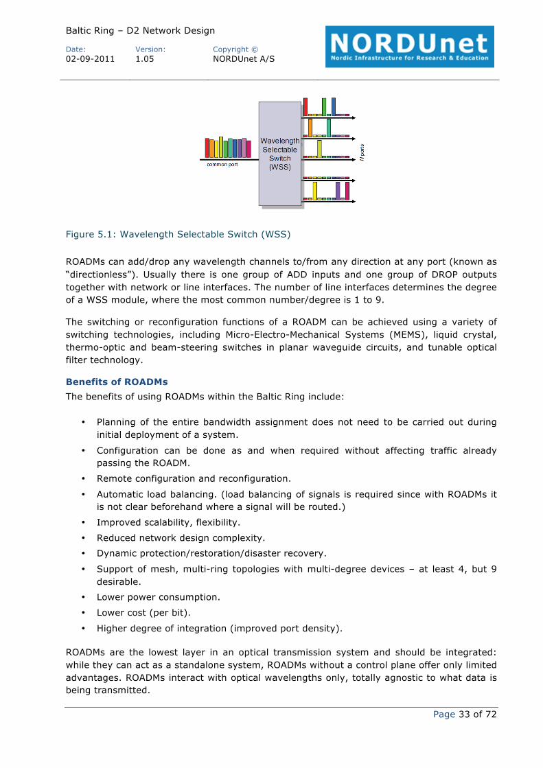
A reconfigurable optical add-drop multiplexer (ROADM) adds the ability to remotely switch traffic from a WDM system at the wavelength layer. This is achieved through the use of, e.g., Wavelength Selective Switches (WSS). This allows individual or multiple wavelengths carrying data channels to be added and/or dropped from the transport link without the need to convert the signals on all the WDM channels on that link to electronic signals and back again to optical signals.
ROADMs based on Wavelength Selective Switches (WSSs) are one of the most commonly used ROADM solutions and can be characterised as Optical-Optical-Optical (OOO) wavelength switches or cross connects, which switch wavelengths between ports called composite or line ports.
ROADMs can add/drop any wavelength channels to/from any direction at any port (known as “directionless”). Usually there is one group of ADD inputs and one group of DROP outputs together with network or line interfaces. The number of line interfaces determines the degree of a WSS module, where the most common number/degree is 1 to 9.
The switching or reconfiguration functions of a ROADM can be achieved using a variety of switching technologies, including Micro-Electro-Mechanical Systems (MEMS), liquid crystal, thermo-optic and beam-steering switches in planar waveguide circuits, and tunable optical filter technology.
Benefits of ROADMs The benefits of using ROADMs within the Baltic Ring include:
• Planning of the entire bandwidth assignment does not need to be carried out during initial deployment of a system.
• Configuration can be done as and when required without affecting traffic already passing the ROADM.
• Remote configuration and reconfiguration.
• Automatic load balancing. (load balancing of signals is required since with ROADMs it is not clear beforehand where a signal will be routed.)
• Support of mesh, multi-ring topologies with multi-degree devices – at least 4, but 9 desirable.
• Lower power consumption.
• Lower cost (per bit).
• Higher degree of integration (improved port density).
ROADMs are the lowest layer in an optical transmission system and should be integrated: while they can act as a standalone system, ROADMs without a control plane offer only limited advantages. ROADMs interact with optical wavelengths only, totally agnostic to what data is being transmitted.
ROADMs can be used to build and deploy many network topologies, including mesh and multi-ring topologies. This is dependent on the degree of ROADMs. With degree 2 ROADMs, no multi-ring or meshing is possible. With degree 9, however, the possibilities are broad and sufficient to meet most requirements.
5.2.1.7 Transmission Capacity and Constraints
A single traffic flow can occupy up to the full wavelength capacity. The capacity of a wavelength can be any of 2.5 Gbps, 10 Gbps, 40 Gbps or 100 Gbps. The modulation schemes that can be used vary from the traditional amplitude-based Non Return to Zero (NRZ) to the state-of-the-art coherent Polarisation Modulation Quadrature Phase Shift Keying (PM-QPSK).
However, transmission of 40 Gbps / 100 Gbps has some requirement implications for the existing DWDM network:
• Addition of new In-Line Amplification (ILA) sites that were previously skipped. • Additional use of Raman pumps • At some ILA sites, introduction of ROADM filters that include per wavelength Variable
Optical Attenuators (VOAs) for gain equalisation purposes. • Avoidance of G.655 fibre, which has degraded performance compared to G.652, when
it comes to high-capacity phase-modulated signals. • Removal of Dispersion Compensation Modules (DCMs), which are used for managing
the accumulation of chromatic dispersion in a static way.
With reference to the avoidance of DCMs, it should be noted that although DWDM networks with 10 Gbps wavelengths require DCMs for managing chromatic dispersion in the optical domain, state-of-the-art coherent receivers (40 Gbps / 100 Gbps) are managing chromatic dispersion and other optical impairments (e.g. polarisation mode dispersion) in the electronic domain. Hence DCMs are not necessary for pure 40 Gbps / 100 Gbps DWDM transmission. Moreover, deployment of DCMs in 40 Gbps / 100 Gbps DWDM networks brings an additional burden to the optical design because:
• Span attenuation is artificially increased. • The strategy of keeping the chromatic dispersion low over the network, which is
extensively used in 10 Gbps DWDM networking via the deployment of DCMs, increases the impact of harmful non-linear effects, such as cross-phase modulation.
Therefore, a DWDM network based purely on coherent transmission at 40 G or 100 Gbps can be expected to have improved regeneration performance compared to a DWDM network used for a mix of coherent transmission and 10 Gbps wavelengths transmission, both having the same amplification technology and dimensioning.
This conclusion means a balance has to be found between the following considerations:
• Supporting a mixture of 10 Gbps, 40 Gbps and 100 Gbps wavelengths brings an additional regeneration/amplification cost to the DWDM network.
• Demand for 10 Gbps wavelengths is not expected to disappear in the next few years and it is not clear whether the prices of 100 Gbps / 40 Gbps transponders will be less than 10 / 4 times the price of a 10 Gbps transponder.
The use of muxponders for carrying 10 Gbps services (10 Gigabit Ethernet or STM-64) over coherent wavelengths could be a way of managing this trade-off.
5.2.1.8 Service Quality Parameters
The Round-Trip Time (RTT) for a wavelength, or the delay, derives mainly from propagation delay, which is fixed and is defined by the following formula [Noutsios]:
t = n* D/c
where:
• t is the latency. • n is the optical fibre’s group refractive index. • D is the length of the optical fibre. • c is the speed of light in a vacuum.
In order to calculate accurately the overall delay, the propagation delay caused by the DCMs should also be taken into consideration. This delay is not negligible, as documented by the experimental results cited in [Noutsios]. But this delay could disappear by deploying coherent-only transmission.
The rule of thumb for the delay in 1000 km fibre is 2x10⁻⁸ sec.
With regard to quality, the wavelength can be expected to have no packet loss and not be subject to jitter.
5.2.2 Market Analysis This section presents information gathered from discussions with vendors at the end of 2010 regarding ultra-high-capacity transmission (40 Gbps /100 Gbps), ROADM availability and control plane availability on optical transmission platforms.
These technologies are all-optical – in other words, analogue. Only one vendor manufactures and promotes so-called digital optical networking and equipment. Some vendors offer a variety of optical amplifiers (Erbium Doped Fibre Amplifier (EDFA), Raman) and other components like compensators of chromatic (CD) and polarisation (PMD) dispersion.
All vendors support ROADM technologies, although there are some important differences that have to be taken into account, for example, the degree of ROADMs, maximum optical reach, control plane developments, and availability of 100 G interfaces.
The information obtained may be summarised as follows:
• Point-to-point DWDM transmission is implemented by all vendors.
• Industry converges on the implementation of coherent polarisation multiplexed transmission for 40 Gbps / 100 Gbps wavelengths using PM-QPSK. Relevant 50 GHz spaced transponders are either already available or will be available during 2011. It should be noted that some vendors state that they have changed their plans for 40 Gbps wavelengths implementation and will skip directly to 100 Gbps implementations.
• 40 Gbps /100 Gbps transmission places more stringent requirements on the optical domain, especially when coupled with 10 Gbps wavelength transmission, leading to degrading of regeneration performance and Raman amplifiers usage. Some vendors state that they plan to release new amplifier families in order to improve 40 Gbps / 100 Gbps transmission performance.
• ROADMs are currently available from most of the vendors with degree at least 8. Moreover, ROADMs with integrated colourless and directionless features are either already available or appear on vendors’ roadmaps for release during 2011.
• An advanced control plane (e.g. GMPLS) for the optical transmission platform is either already available or appears on vendors’ roadmaps for 2011, in most cases.
5.2.3 Summary ROADMs are beneficial and perhaps essential to all Baltic Ring services, especially for the dynamic services, because of their all-optical nature and truly reconfigurable capabilities. ROADMs can offer the following benefits, which cannot be achieved with other components:
• Very good scalability and flexibility compared to old solutions with fixed OADM. • Dynamic protection/restoration/disaster recovery. • Proactive possibilities for planned maintenance – no outages. • Automated bandwidth-on-demand services. • Reduced network design complexity. • Protocol/service/bit rate transparency: 10 G / 40 G or even 100 G Ethernet or OTN
signals. • Optical monitoring, which is important for new all-optical services. • Support of mesh, multi-ring topologies. • Higher degree of integration (improved port density). • Lower power consumption. • Lower cost.
There are many ROADMs available on the market, integrated in modern optical DWDM transmission systems, with many diverse features. ROADMs are not dependent on other technologies; rather they serve as the basic building blocks at the lowest layer.
5.3 Next-Generation Optical Transport Network The challenge for Next-Generation Optical Transport Network (NG-OTN) is to address the delay sensitivities of data networking whilst utilising an OAM-rich architecture – all at ultra-high capacity. In these respects, the OTN revival symbolises not only a new technology and architectural design, but also an entirely new approach to transport networking.
NG-OTN is the newest concept of converged core transport architecture, designed more for Ethernet than for telecommunications traffic, and formed of a collection of OTN standards initially written a decade ago – but being renewed and developed by ITU-T Study Group 15 (SG15), with input from other standards bodies. The outcome should make Next-Generation OTN more flexible and help realise its potential.
This section presents the key features of OTN and Next-Generation Optical Transport Network (NG-OTN), which are seen as possible technologies in the evolution of digital and analogue backbone transmission for both the commercial and NREN community, providing support for Time-Division Multiplexing (TDM), packet and IP services. It pays particular attention to the client-mapping extensions ODU0 and ODUFlex. The section concludes with a market analysis of OTN-based equipment functionality capable of switching and multiplexing ODUx, including ODUFlex.
5.3.1 Optical Transport Network
The Optical Transport Network (OTN) architecture concept was initially developed by the ITU-T a decade ago, to build upon the SDH and DWDM experience and provide bit rate efficiency, resiliency and management at high capacity. OTN therefore looks a lot like SONET/SDH in structure, with less overhead and more management features. It does, however, bring many developments and advantages over SDH:
• Transparent Client Signals:
This allows the end user to view exactly what was transmitted at the far end and decreases the complexity of troubleshooting.
• Better Forward Error Correction:
OTN has increased the number of bytes reserved for Forward Error Correction (FEC), allowing a theoretical improvement of the Signal-to-Noise Ratio (SNR) by 6,2 dB. This improvement can be used to enhance the optical systems in the following areas:
○ Increase the reach of optical systems.
○ Increase the number of channels in the optical systems.
○ Ease the introduction of transparent optical network elements, such as OADMs, Photonic Cross Connects (PXCs), splitters, etc.
• Better scalability:
The old transport technologies like SONET/SDH were created to carry voice circuits, which is why the granularity was very dense – down to 1,5 Mbps. OTN is designed to carry a payload of greater bulk, which is why the granularity is coarser and the multiplexing structure less complicated.
• Tandem Connection Monitoring:
The introduction of additional Tandem Connection Monitoring (TCM) combined with the decoupling of transport and payload protocols allow a significant improvement in monitoring signals that are transported through several administrative domains, e.g. a meshed NREN topology where the signals are transported through several other NRENs before reaching the end users.
In a multi-domain scenario – “a classic carrier’s carrier scenario” where the originating domain can’t ensure performance or even monitor the signal when it passes to another domain – TCM introduces a performance monitoring layer between line and path monitoring allowing each involved network to be monitored, thus reducing the complexity of troubleshooting as performance data is accessible for each individual part of the route.
Finally, a major drawback with regard to SDH is that a lot of capacity during packet transport is wasted in overhead and stuffing, which can also create delays in the transmission, leading to problems for the end application, especially if it is designed for asynchronous, bursty communications behaviour. This over-complexity is probably one of the reasons why the evolution of SDH has stopped at STM 256 (40 Gbps).
OTN has all the capabilities required to monitor, manage, and control each client signal transported on a per wavelength basis in the network. In this way, OTN adds operation, administration and maintenance (OAM), and provisioning and troubleshooting functionality to optical carriers.
5.3.2 ODU0 and ODUFlex The OTN client-mapping capabilities were extended to support new requirements. ODU0 was added to support efficient transparent transport of GE signals over OTN. It was required because if a GE were to be mapped into an ODU1, half of the bandwidth would be wasted. However, an ODU0 container is half the size of an ODU1. This allows the mapping of two ODU0s into an ODU1 (as shown in Figure 5.2), which is then mapped into an OTU1. Notice that OTU0 does not exist.
Figure 5.2: OTN ODU0
Additionally, ODUFlex was developed to accommodate signal rates of different speeds; it is sized to occupy the minimum number of time slots in a higher order ODUk. The client mapping is done so that the ODUFlex container has the exact size of its client, leaving the remaining space for other client signals as shown in Figure 5.3. ODUFlex supports Constant Bit Rate (CBR) clients and packet-based clients. CBR clients are mapped by using Bit-Synchronous Mapping Procedure (BMP) and packet-based client signals are accommodated by using Frame-mapped Generic Framing Procedure (GFP-F). ODUFlex is then mapped into a number of time slots in a High-Order ODU (HO-ODU) by using Generic Mapping Procedure (GMP).
The current trend is that DWDM systems are enhanced – or have an equipment add-on – to be capable of handling digital OTN switching or grooming in direct integration with their traditional analogue handling of OTN. In addition, packet and TDM, as edge technologies, are groomed into OTN using ODUFlex, as shown in Figure 5.4Figure 5.3 below. In this way, DWDM and transport systems converge into a single DWDM/transport unit.
Figure 5.4: Integrated digital OTN switching or grooming using ODUFlex
This can be described more precisely as sub-port level grooming, which offers a high level of grooming flexibility and optimises transport efficiency for networks with a significant volume of point-to-point traffic in the service mix. The sub-port grooming option allows maximum grooming flexibility by enabling VLANs or pseudowires within a port to be logically mapped to optical links using ODUFlex.
Sub-port level grooming also enables finer granularity by supporting sub-port interfaces or virtual interfaces such as VLANs, which means that ports do not have to consume the full capacity of a physical port or wavelength. Different VLANs from the same transport node are mapped to different virtual containers through the transport network to different destinations using ODUFlex and VLAN shaping.
ODUFlex is a new technology that allows grooming of traffic between optical transport equipment and routers in a manner that efficiently addresses incremental bandwidth growth in steps as granular as 1 Gb. Carriers no longer have to allocate a full ODU container to each connection, but rather can increase capacity in increments for connections that require them. Through control plane integration, dynamic bandwidth adjustments can be made to optimise
the network as needed over time. Further opportunities for enhancing overall network resiliency and fault isolation also emerge from control plane integration.
NG-OTN will provide improvements to service-layer networking efficiency, protection and restoration functions, scalability and flexibility.
5.3.3 Market Analysis This section outlines equipment functionality capable of switching and multiplexing ODUx, including ODUFlex. It presents information gathered from discussions with vendors at the end of 2010 / beginning of 2011 regarding OTN-based equipment. The discussions identified that several vendors have recently launched digital OTN switches ranging from Gigabit to Terabit switching capacity.
The most common available functionality is:
• TDM support. o Full non-blocking OTH switching and multiplexing. o Full non-blocking SDH/SONET switching and multiplexing. o Line rates from 155 Mbps to 100 Gbps. o TCM Support
• Packet support. o 1 GbE, 10 GbE, 100 GbE. o Note that this support is more mature for point-to-point and “switching on a
blade” rather than in terms of device-wide packet switching. • WDM Support.
o Close integration with WDM systems either as an independent switch or as a subsystem in a DWDM system.
• Control plane support. o GMPLS allowing automatic restoration.
OTN switches are the glue between domains when interconnecting on the OTN level. They are especially suited to larger interconnects where several domains interconnect.
The use of OTN switches matches the Carrier Class Transport infrastructure requirements with excellent integration into a DWDM or managed wavelength infrastructure. In addition, they support packet, TDM or IP/MPLS traffic flows.
5.4 Carrier Ethernet The original Ethernet technology is not well suited as a shared-media network for service provider applications. For example, it is more or less impossible to keep traffic isolated, which prevents the implementation of private circuits. However, Ethernet has evolved constantly, and there are now different types of carrier Ethernet (cE) technologies which are bound by requirements that qualify them as carrier grade. For instance, a carrier grade network is expected to provide services without interruption; it needs to be well tested; and it should be able to deliver the expected services technologies that have been developed for Quality of Service (QoS), recovery and restoration of circuits, and extensive management features.
The Metro Ethernet Forum (MEF) has defined the functional requirements for a transport service to satisfy their standard of Carrier Class Ethernet [MEF_WhatCE]. This consists of five groups of requirements, as follows:
• Standardised Services: The services must be able to provide transparent LAN services for point-to-point and (multi)point-to-multipoint topologies, based on standard definitions of such characteristics as bandwidth, resilience and service multiplexing, allowing customers to compare service offerings and facilitating service level agreements. MEF has identified three service categories:
○ E-Line: a service connecting two customer Ethernet ports over a WAN.
○ E-LAN: a multipoint service connecting a set of customer end points, giving the appearance to the customer of a bridged Ethernet network connecting the sites.
○ E-Tree: a multipoint service connecting one or more roots and a set of leaves, but preventing inter-leaf communication.
• Scalability: Technologies used must be able to operate in large and complex networks. Scalability spans metro, access and core areas of the network.
• Reliability: The network must be able to react to disruptions. Recovery and restoration technologies must be able to provide an always-there service to customers. 50 ms recovery times are the industry standard set by the widely deployed SONET/SDH systems.
• Quality of Service (QoS): The network should be able to comply with the different quality levels and parameters specified in Service Level Agreements (SLAs) with customers. The contracted SLA may be defined in terms of bandwidth, maximum jitter and delay and/or other network parameters.
• Service Management: Operators must be able to monitor and diagnose the network. Extensive OAM features should be part of the carrier grade solution.
Native Ethernet services are carried across wide area networks using other technologies like the Carrier Ethernet service.
The following subsections cover:
• Ethernet extensions.
• Ethernet over Multi-Protocol Label Switching (EoMPLS).
• Ethernet over PBB/PBT.
• Ethernet over Multi-Protocol Label Switching Transport Profile (MPLS-TP).
Ethernet over OTN is described in Section 5.3. Ethernet over SDH is not included as it is considered obsolete.
5.4.1 Ethernet Extensions This section summarises the new protocols that have been added to the IEEE standards 802.1 and 802.3 to make Ethernet suitable for use as a carrier grade transport protocol, namely, OAM, Operational Support System (OSS), QoS and Layer-2 routing.
Ethernet OAM provides end-to-end service management, which is important in the multi-operator environment of the Baltic Ring. Ethernet OAM will allow NRENs to create, monitor, and troubleshoot Ethernet links and services in a standardised fashion. The following protocols are the required building blocks for Ethernet OAM:
• ITU-T Y.1731: OAM functions and mechanisms for Ethernet-based networks [ITU-T Y.1731].
• IEEE 802.3ah: Ethernet Link OAM (EFM OAM) [IEEE 802.3ah].
• MEF 16: Ethernet Local Management Interface [MEF 16].
5.4.1.2 Operational Support System (OSS)
An additional requirement for carrier class operation is a fully featured Operational Support System (OSS). This GUI-based interface will allow rapid service deployment and maintenance, and is needed for:
• Path creation/deletion/configuration.
• Alarm diagnosis.
• Accessing performance monitoring data.
5.4.1.3 QoS
All of the technologies are inherently based on statistical multiplexing of packets. Compared to a TDM-based technology this would result in a statistical multiplexing gain, i.e. more efficient use of trunk capacity. The down side of statistical multiplexing is the risk of packet loss due to congestion. To ensure that services have guaranteed throughput, Ethernet needs quality of service protocols.
The IEEE 802.1D-2004 specification [IEEE 802.1D-2004] Annex G “User priorities and traffic classes” describes traffic classes and gives a foundation for “soft” QoS, where some traffic classes receive better treatment than others.
IEEE is preparing some standards to define the implementation of hard QoS in Ethernet:
• IEEE 802.1Qav Forwarding and Queuing Enhancements for Time-Sensitive Streams (also known as Queuing and Forwarding Protocol (QFP), approved in December 2009) [IEEE 802.1Qav].
The SRP protocol is similar to RSVP: it is able to book enough resources along the traffic path to guarantee the required QoS metrics. QFP defines algorithms for QoS mechanisms, including ingress metering, priority regeneration, shaping and time-aware queue draining.
Layer-2 routing is designed specifically for Layer 2 devices such as Ethernet. These build on the well-known L3 routing protocols. There are currently several initiatives that aim to develop the Layer 2 routing protocol:
• Provider Link State Bridging (PLSB): proprietary routing protocol from Nortel, proposed to the IEEE 802.1aq Shortest Path Bridging Working Group [NortelPLSB].
• Shortest Path Bridging (SPB): from the IEEE (802.1aq). This project group is working on two different flavours of SPB: SPB VID (SPBV) and SPB MAC (SPBM) [IEEE 802.1aq, IETF SPB IS-IS].
• Transparent Interconnection of Lots of Links (TRILL): from the IETF [IETF TRILL].
In summary, several new protocols that enhance Ethernet to provide carrier grade performance have either been recently released or are still in standardisation. Vendors may offer some combination of these protocols to provide an Ethernet-based carrier grade solution, However, not many such solutions have been made available yet and are suppressed in many vendor roadmaps.
5.4.2 EoMPLS Ethernet over IP/MPLS (Internet Protocol/Multi-Protocol Label Switching) is one of the technologies that can be used to transport Ethernet frames over a provider’s backbone network. In essence, the subscriber will get an Ethernet interface on copper or fibre. The customer's Ethernet packet is transported over MPLS and the service provider network uses Ethernet again as the underlying technology to transport MPLS. So, it is Ethernet over MPLS over Ethernet.
Although MPLS is said to be complex, it is also popular in big providers’ networks and over the years of its deployment it has proved its reliability and scalability.
The Metro Ethernet Forum (MEF) has defined three types of services that can be delivered through Metro Ethernet. All three services types can be delivered by different services provisioned on top of the MPLS transport:
• E-Line (point-to-point service type) can be provisioned as Virtual Private Wire Service (VPWS).
• E-LAN (multipoint-to-multipoint service type) can be provisioned as Virtual Private LAN Service (VPLS).
• E-Tree (point-to-multipoint service type) can be provisioned as Virtual Private Multicast Service (VPMS).
The three services listed above are referred to as Layer 2 Virtual Private Networks (L2VPN). Figure 5.5 shows the reference model for L2VPNs. The model identifies the customer equipment (CE) which is connected to the provider network, provider edge equipment (PE) to which customer access links are connected, and the MPLS-enabled core of the provider network. The provider network can support multiple instances of L2VPNs which are logically separated from each other – customer traffic will never be forwarded between L2VPNs.
Figure 5.5: Reference model for L2VPNs (source: [RFC4665])
All the services operate over pseudowires (PW) defined by the IETF PWE3 working group. A pseudowire means an emulated point-to-point connection over a packet-switched network (PSN) that allows the interconnection of two nodes with any Layer 2 technology. The important feature of the pseudowire technology is that the service-specific functions are located only on the edge of the provider network, while in the core only MPLS label-switched paths (LSPs) are established. This way the core routers do not need any knowledge about the services provided by the network, which increases the scalability of the services and reduces the complexity of the core routers.
5.4.2.1 Services
There are six services defined by the Metro Ethernet Forum (MEF) for Metro Ethernet Networks. The services are specified in [MEF6.1] and are as follows:
• Ethernet Private Line and Ethernet Virtual Private Line – E-Line type services.
• Ethernet Private LAN and Ethernet Virtual Private LAN – E-LAN type services.
• Ethernet Private Tree and Ethernet Virtual Private Tree – E-Tree type services.
All the six services specified by MEF can be provisioned as Layer 2 Virtual Private Network using the services specified by IETF for L2VPNs:
Virtual Private Wire Service (VPWS) A Virtual Private Wire Service (VPWS, also referred to as Virtual Leased Line or Ethernet over MPLS) is a point-to-point circuit (link) connecting two Customer Edge (CE) devices. The link is established as a logical channel through a packet-switched network. The CE in the customer network is connected to a PE (Provider Edge device) in the provider network via an Attachment Circuit – either a physical or a logical circuit. [RFC4026].
The Provider Edge (PE) device does a simple mapping between the pseudowire and a physical or logical access interface, allowing the creation of the Ethernet Private Line Service (with the use of a physical interface) or the Ethernet Virtual Private Line Service (with the use of logical interfaces – VLANs) as defined by the Metro Ethernet Forum in [MEF6.1].
The technology does not require any knowledge about customer MAC addresses, which reduces the amount of information that must be learnt and stored by the PE devices.
A VPWS is an E-Line service as defined by MEF.
Virtual Private LAN Service (VPLS) A Virtual Private LAN Service (VPLS) is a provider service that emulates the full functionality of a traditional Local Area Network (LAN). A VPLS makes it possible to interconnect several LAN segments over a packet-switched network (PSN) and makes the remote LAN segments behave as one single LAN [RFC4026].
The provider network emulates a traditional LAN switch, which makes its forwarding decisions based on MAC addresses. MAC addresses must be learnt by the PE devices in the same way the traditional LAN switches do so. Ethernet frames with broadcast or unknown (i.e. not yet learnt) destination MAC addresses are forwarded to all CE devices connected to a VPLS.
Access interfaces to a VPLS service may be either physical or logical, allowing the creation of both the Ethernet Private LAN Service and Ethernet Virtual Private LAN Service as defined by the Metro Ethernet Forum in [MEF6.1].
A VPLS is an E-LAN service as defined by MEF.
Virtual Private Multicast Service (VPMS) A Virtual Private Multicast Service (VPMS) is defined as a Layer 2 VPN service that provides point-to-multipoint connectivity for a variety of Layer 2 link layers across an IP or MPLS-enabled packet-switched network.
The standardisation of this service has not yet been completed by IETF. Service level requirements and a framework for the service have been proposed in an IETF Internet Draft which is a working document only [draft-ietf-l2vpn-vpms-frmwk-requirements-02].
A VPMS is a point-to-multipoint service that allows a single stream of Ethernet frames transmitted by a CE (sender) to be replicated in the provider network and delivered to multiple CEs (receivers) connected to the same VPMS instance.
An important limitation in the model proposed by the above-mentioned Internet Draft is that all CEs connected to VPMS must be configured as sender or receiver and not both. Also, each access circuit must be associated with the role of either sending or receiving. (However, reverse traffic may be optionally supported.) This limitation does not comply with the requirements for an E-Tree service proposed by the Metro Ethernet Forum in MEF 6.1, which allows multiple senders in a single E-Tree instance.
For efficient replication of customer traffic in the provider network, point-to-multipoint pseudowires can be used between the single sending CE and multiple receiving CEs. In the case of MPLS-based VPN, a point-to-multipoint LSP can be used.
Provider Backbone Bridge Traffic Engineering (PBB-TE) is the third (and latest) standard developed by the IEEE with the aim of giving providers a Layer 2 carrier-grade transport based on classical Ethernet.
Provider Bridge (PB) and Provider Backbone Bridge (PBB) standards solved the problem of the scalability and manageability of a provider network that uses Ethernet functionality both as a customer service and as an internal transport. However, such important features as fast resilience and traffic engineering were left unanswered. PBB-TE [IEEE802.1Qay] is one of the possible solutions to adding these features to carrier Ethernet.
Initially the task was fulfilled by Nortel, who developed a proprietary technology called Provider Backbone Transport (PBT); afterwards, based on this technology, a standard technology called Provider Backbone Bridge Traffic Engineering was developed by the IEEE (it was approved in June 2009).
PBB-TE is a technology that supports connection-oriented deterministic paths with PBB framing and fast-path protection switching technique.
To achieve these objectives PBB-TE makes the following changes in PBB functionality:
• Switches off learning of backbone MAC addresses.
• Switches off STP functionality of backbone switches.
• Uses a combination of B-VID and B-DA as a path label.
• Assumes a manual or NMS-based building of forwarding tables.
PBB-TE uses addressing in a different way to the classical Ethernet and PB/PBB technologies. According to the 802.1Q approach, a VID (VLAN ID) typically identifies a loop-free domain in which MAC addresses can be flooded.
If we choose to configure loop-free MAC paths instead of using flooding and learning, the VID is freed up to denote something else. PBT employs this concept by allocating a range of VIDs to identify specific paths through the network to a given destination MAC address. Each VID is then locally significant to the destination MAC address only, and since the MAC address is still globally significant, the combination of backbone B-VID + B-MAC (60 bits) becomes globally unique.
PBB-TE allocates a range of VID/MAC addresses whose forwarding tables are populated via the management or control plane instead of through the traditional flooding and learning techniques. Suddenly Spanning Tree and all its associated constraints and problems disappear. The switch still behaves largely as with traditional Ethernet: forwarding data to its intended destination. The combination of B-VID + B-MAC could be compared to an MPLS label, but in the case of PBB-TE this label is not “switched” as it retains its value along the path from the source to the destination.
PBB-TE defines an Ethernet Switched Path (ESP), which is a backbone connection with a deterministic path. ESP is a tier-one path, which roughly corresponds to a PBB backbone VLAN or an MPLS tunnel (i.e. an LSP of tier one). Within an ESP a number of customer logical connections may exist; these connections are determined by I-SID values exactly as in the PBB model. While ESP is a standard term, vendors of PBB-TE equipment use also other terms like “tunnel” or “trunk” for this entity.
5.4.3.2 Services
Two types of PBB-TE-based services are defined by standard 802.1Qay:
• Point-to-point (E-Line type).
• Point-to-multipoint (E-Tree type).
A point-to-point service is supported by two point-to-point ESPs where the ESPs' endpoints have the same backbone MAC addresses.
A point-to-multipoint TE service instance is supported by a set of ESPs that comprises one point-to-multipoint ESP from a root to each of n leaves plus a point-to-point ESP from each of the n leaves to the root. This type of service uses Layer 2 multicast and is aimed at multimedia applications.
It is also possible to build an any-to-any TE service based on sets of point-to-point ESP if the VPLS approach is followed. In such a case, these point-to-point ESPs and point-to-point I-SIDs should create full-mesh connectivity between Backbone Edge Bridges that use this connectivity to send copies of ingress customer frames to a required destination. The split horizon technique, which is used by VPLS, could be applied to avoid loops. The 802.1Qay standard doesn’t describe any-to-any services; however, there is at least one proprietary implementation of it [Ethos].
PBB-TE services are Layer 2 VPN services; they connect customer sites (pairs or groups) without taking into account any IP information.
5.4.3.3 QoS
There are no specific QoS standards for PBB-TE, meaning that all QoS techniques developed for Ethernet are applicable to PBB-TE networks. At the same time, the traffic engineering capability of PBB-TE makes the technology “QoS-enabling”, which means that if necessary QoS metrics can be guaranteed with some quantitative limits.
The deterministic paths of PBB-TE make the admission control procedure of QoS, which is the crucial element of QoS provisioning, much more consistent and robust compared to the uncertain hop-by-hop paths of IP and classical Ethernet.
The current situation with regard to admission control for PBB-TE is that it should be done manually or by means of some central provisioning system/NMS, as at the moment there are no distributed protocols like RSVP to fulfil this procedure by PBB-TE switches themselves in a distributed manner. However, there are some initiatives ongoing that might result in such a
protocol. One of them is being carried out by the IETF CCAMP working group; the latest Internet Draft for this is called “Generalized Multiprotocol Label Switching (GMPLS) control of Ethernet PBB-TE” [IETF GMPLS].
5.4.3.4 Protection and Restoration
PBB-TE uses a path protection mechanism to provide resilient connections. The PBB-TE path protection mechanism uses two deterministic paths (i.e. ESP): primary and backup. Their purpose is very similar to SDH working and protection paths, namely, all customer connections are switched to a backup path when the failure of a primary path is detected. PBB-TE uses Connectivity Fault Management (CFM) (CCM heartbeat messages) as the main failure detection mechanism.
5.4.4 Multi-Protocol Label Switching – Transport Profile (MPLS-TP) Multi-Protocol Label Switching – Transport Profile (MPLS-TP) is a profile of IP/MPLS designed to meet transport network operational requirements. It takes key elements from IP/MPLS such as MPLS / Pseudowire Emulation Edge to Edge (PWE3) architecture and forwarding mechanisms, and, optionally, GMPLS control plane, and provides additional functionality such as performance monitoring, OAM, Tandem Connection Monitoring (TCM), protection switching and ring protection.
The main characteristics of MPLS-TP are:
• It is connection oriented. MPLS-TP uses LSPs and PW to deliver point-to-point services but also point-to-multipoint and multipoint-to-multipoint services.
• Client agnostic. MPLS-TP is able to carry any type of client traffic such as Asynchronous Transport Mode (ATM), SDH, Ethernet, etc.
• Transport layer agnostic. MPLS-TP can run over Ethernet, SONET/SDH (G.783), OTN (G.709 [ITU-T G.709], G.872 [ITU-T G.872]) using Generic Framing Procedure (GFP) (G.7042) and Wavelength-Division Multiplexing (WDM).
• Provides OAM. Provides OAM capabilities similar to those provided by SDH and OTN.
• Provides recovery mechanisms similar to those provided by traditional transport networks.
• Network provisioning via centralised Network Management System (NMS) or optional distributed control plane. This gives the possibility of manual or dynamic provisioning and the possibility of transport rerouting without manual intervention.
The characteristics of MPLS-TP are a consequence of the list of requirements stated in RFC 5654 [RFC5654]. The list was put in place to ensure that MPLS-TP would meet the demands of carrier networks and to provide a set of recommendations. The requirements are divided into general, layering, control plane, and protection and recovery. A complete list can be found in [RFC5654].
5.4.4.1 MPLS-TP Architecture and Network Model Components
MPLS-TP is an extension of the already established MPLS protocol and uses the same forwarding mechanisms and architecture as traditional MPLS. Its architecture includes OAM, control plane, protection, and network management. These are covered in following sections.
The components forming an MPLS-TP network model are shown in Figure 5.6 below. As already mentioned, these components do not introduce new functionality to MPLS-TP and have the same behaviour as in MPLS.
Figure 5.6: MPLS-TP network model
As shown in the diagram, an MPLS-TP network includes the following components:
• MPLS-TP Label Switching Router (MPLS-TP LSR). Can either be an MPLS-TP Provider Router (MPLS-TP PR) or an MPLS-TP Provider Edge Router (MPLS-TP PER) for a given path. A router can take both roles if necessary. An MPLS-TP LSR performs label switching and is in charge of maintaining the forwarding tables.
• MPLS-TP Label Edge Router (MPLS-TP LER). Can be found at the edge of an MPLS network. An MPLS-TP LER performs label push at the ingress for incoming packets and pops the labels at the egress for outgoing packets.
• MPLS-TP Provider Edge Router (MPLS-TP PER). Is in charge of adapting client traffic and encapsulates the traffic to be carried over an MPLS-TP Label Switched Path (MPLS-TP LSP). An MPLS-TP PE can be either a Switched PE (S-PE) or a Terminating PE (T-PE). A T-PE is able to terminate the PW and is present at the first and last segment of a PW. An S-PE is able to perform the label swap of a PW.
• MPLS-TP Provider Router (MPLS-TP PR). Is in charge of switching LSPs with client traffic. It does not perform any adaptation function.
• MPLS-TP Customer Edge Router (MPLS-TP CER). Is in charge of interfacing with MPLS-TP networks. However, they are not aware of the existence of any MPLS-TP networks.
5.4.4.2 MPLS-TP Layering
MPLS-TP layering is a major requirement, as stated in RFC 5654. Layering has several advantages and therefore it is very important that the MPLS-TP protocol complies with these requirements. A layered network provides complete separation and independence between layers and OAM separation for each layer. It also provides separation of control plane activities, meaning that the control plane of a client network is isolated from the control plane of the other layers, such that control plane operation of the client layer does not have any effect on the control plane of the server layer.
The different layers as described in ITU-T G.805 [ITU-T G.805] are shown in Figure 5.7 below.
Figure 5.7: MPLS-TP layering
One of the advantages of MPLS-TP and layering is that it can act as a server layer for other protocols and be carried by other protocols acting as server layers for MPLS-TP such as SDH, OTN or Ethernet. This gives the layering concept a sense of relativity.
The transport path layer has several components that are used to carry the traffic in MPLS-TP. As mentioned above these transport elements are the same as those already used in traditional MPLS. Figure 5.8 shows the hierarchy of the transport path layer:
Figure 5.8: Transport layer components
Physical Media The physical media is the media used to connect two network elements. The physical media could also be another server layer, such as SDH or OTN.
Section Layer A section is part of the server layer and provides transfer of section-layer client information between adjacent nodes.
Label Switched Path (LSP) A Label Switched Path (LSP) is a path through an MPLS network set up by a signalling protocol like Label Distribution Protocol (LDP). An MPLS-TP LSP supports 1+1, 1:1 and 1:n
protection, is traffic engineered, uses OAM, and can eventually be established and maintained by a control plane protocol. It can be point to point and point to multipoint.
Pseudowire (PW) A pseudowire is an emulation of a Layer-2 point-to-point connection oriented service. A PW can be a Single-Segment PW (SS-PW) or a Multi-Segment PW (MS-PW). An SS-PW is a PW set up directly between two MPLS-TP T-PEs. The PW label remains unchanged between the two T-PEs. An MS-PW is a set of two or several PW segments that act like an SS-PW. Each MS-PW terminates at a T-PE and the PW label is swapped at the S-PE.
Depending on the needs and application, MPLS-TP can use either LSPs or PW to carry client traffic. This means that MPLS-TP network operators can carry user traffic directly over an LSP, discarding the need to use a PW. For example, an MPLS-TP network can be used to carry IP traffic directly over an LSP; in this case a PW would not be necessary.
5.4.4.3 Traffic Adaptation
Traffic adaptation is the process by which client traffic is encapsulated to be carried via a PW or LSP. Traffic adaptation is done at the MPLS-TP PE both at the ingress and at the egress. Notice that client traffic is completely transparent to the MPLS-TP layer. Adaptation of client traffic can be done using either PWs or LSPs.
5.4.5 Market Analysis This section presents information gathered from discussions with vendors at the end of 2010 and beginning of 2011 relating to Carrier Ethernet switching technologies.
5.4.5.1 IP Services
Three kinds of hardware platform are normally considered when building a network that provides an IP service:
The high-performance IP core router is a hardware platform designed for “carrier of carriers” networks. The devices are 100 Gbps ready, with slot capacity up to 200 Gbps. They are able to support many kinds of network interfaces (Packet over SDH (PoS), Ethernet, etc.), but as a consequence are more expensive.
Multi-service routers are designed to provide not only IP services but also MPLS-based Layer 2 VPNs (VLL/VPLS). In most cases the devices are equipped with Ethernet interfaces (1 GE, 10 GE, 100 GE). The devices allow transiting of IP or MPLS traffic and service termination and aggregation. Because of unified architecture (focused on Ethernet interfaces/switching) they are less expensive than IP core routers.
The core MPLS switch (LSR) is an MPLS-optimised platform which has been designed specifically to address the scale at which next-generation networks are growing. The platform has been optimised for speed whilst maintaining network economics. This has been achieved by placing the emphasis on MPLS forwarding while still providing the full MPLS/IP
control plane. In this manner the platform does not need to perform costly routing table IP lookups but can rely on more efficient MPLS label lookups.
Control Plane Issues For IP services, fixed circuit services requiring less than full wavelength and dynamic services, the well-known and standard protocols are used (IS-IS, OSPF, Multi-protocol Border Gateway Protocol (MBGP), RSVP, traffic engineering extensions to IGPs).
No issues are expected within single autonomous system signalling. However, currently some limitations exist with multi-domain signalling for fixed circuit services requiring less than full wavelength and dynamic services; an external provisioning tool can be used as a workaround.
Protection/Restoration MPLS-based protection and restoration mechanisms such as global protection (standby LSP) and local protection (Fast Reroute) can also be used for IP services when IP over MPLS switching is used.
5.4.5.2 Carrier Ethernet Solutions
The market analysis has shown that no reliable, fully featured standalone carrier Ethernet solutions are currently available in the market. However, a review of the available transport products’ technology reveals that many of the vendors are moving towards a Packet Optical Transport Service (POTS)-type architecture based on a converged packet and TDM solution capable of delivering a flexible and reliable access grooming and transport layer.
Control plane implementations take advantage of mature IP control plane protocols. In fact, many of the implementations rely on an IP control plane where some useful extensions have been added to open the control plane to the requirements of the next-generation network (NGN). At the moment, MPLS-TP seems to be the de facto standard switching technology available on almost all carrier Ethernet-based equipment.
The traffic engineering (TE) extensions to MPLS make it possible to implement a connection-oriented packet-switched network where cost, reliability and throughput are the key transport network requirements.
Current POTS offerings that include a full carrier Ethernet component are based on first releases. This may be ascribed to the POTS concept being relatively new. These products therefore require an integration phase in which carrier Ethernet functions are incorporated into the ROADM/OTN equipment, then L2 cards can be rapidly added as and when needed.
Typically, the ROADMs that are POTS-enabled offer either OTN or L2 switching; a few solutions offer both. However, since POTS is an emerging technology, further analysis is required in order to understand fully any constraint imposed by the architecture of POTS products.
The OSS software available with current carrier Ethernet platforms needs to be sufficiently mature and reliable to allow a real no-touch switched network. The information gathered to date is not sufficient to confirm that this is the case, therefore deeper investigation is required in the next stage of the Baltic Ring feasibility study.
It should be noted that the OAM protocols available on the equipment are key to efficient network supervision and management and fast recovery in case of major faults. Complete statistical information needs to be available to keep track of bandwidth usage and service quality in order to support sophisticated network planning. Alarms and recovery schemas need to be sufficiently mature and reliable to support traffic rerouting for planned upgrade or repair events.
The integration of carrier Ethernet into ROADMs and/or OTN switches makes it possible to deliver the Baltic Ring services with a single Packet Optical Transport Service solution.
The Baltic Ring network architecture that best leverages the value of carrier Ethernet is the model in which IP is a centralised service with L2 + TDM transport layer providing access. The IP layer can be centralised and the services can take full advantage of having the carrier Ethernet layer as the transport layer. In order to perform efficient and flexible L2 VPN service deployment, MPLS becomes a key technology in the access layer as in the transport and service layer.
In general, carrier Ethernet supports flexible and efficient service delivery for Baltic Ring services. The Baltic Ring IP service can be carried over carrier Ethernet – L2 frame switching can be performed before the IP packet payload is processed. For Baltic Ring layer 2 service, carrier Ethernet may be sufficient on its own for delivery of L2 E-LAN and E-Line services.
For Baltic Ring bit-transparent service, carrier Ethernet could be used to aggregate circuits with bandwidth requirements lower than the wavelength deployed.
In conclusion, many vendors’ carrier Ethernet implementations presented as part of POTS solutions are based on first releases. However, in general, carrier Ethernet is becoming sufficiently mature and flexible to be used in a future Baltic Ring network, especially if a good and complete OSS system is available.
5.5 Technological Considerations The layered architecture proposed for the Baltic Ring network – the layers being optical transport, switching and IP – is not new compared to telecommunication networks of today. What is new is a greater possibility to make use of advances in the DWDM transmission layer, which allows circuit switching of whole wavelengths and sub-wavelength switching based on TDM or packet-oriented approaches or both. This is due to the introduction of increased flexibility (agility) in DWDM transmission systems, which is itself based mainly on the widespread availability of tunable and wavelength-selective switching components, and the area of digital switching. In addition, advances in optical transmission capabilities mean that single-channel 100 Gbps wavelength is now available and is going to be a key part of the evolution of the northern European network infrastructure.
It is therefore mandatory that the Baltic Ring is constructed with a base DWDM layer that can be provided in two possible ways:
• As dark fibre DWDM infrastructure, i.e. self-provided wavelengths provisioned over owned (actually, leased) dedicated fibre that is lit using a carrier-grade DWDM transmission.
• As managed DWDM infrastructure, provided by a third party (i.e. an NREN or a commercial operator) offering full wavelength services.
On top of that there should be a switch or multiplexed TDM and packet layer, supporting an IP service layer where the intelligence is located either in the NREN domain or centralised.
There are several implementation options for the switching layer, which can be realised with an OTN switching capability, a carrier Ethernet capability or with an MPLS-focused IP capability.
The Baltic Ring network architectural components and possible implementation alternatives are therefore as follows:
1. IP component: edge IP capability, BGP4 routing and interfacing, MPLS support.
2. Switching component: a. Carrier Ethernet implemented by equipment that supports:
i. Native Ethernet enhanced with OAM and QoS.
ii. Layer 2 routing. iii. MPLS-TP.
iv. PBB-TE.
v. EoMPLS. b. OTN/NG-OTN implemented by equipment capable of ODU-x switching. Note
that the other functionalities of OTN/NG-OTN, e.g. error correction, are viewed
as an integral part of the optical transmission component. 3. Optical transmission component:
a. Agile transmission allowing circuit switching, implemented by optical
transmission equipment including ROADMs with colourless and directionless features.
Note that the switching layer has several functions:
• It can potentially be the basis for the IP service layer, allowing edge equipment, BGP4 capability, and other IP service equipment to interconnect at high bandwidth.
Specifically, it allows NREN edge routers to connect to remote Baltic Ring routers rather than to local ones.
• It provides the infrastructure for the Baltic Ring Flex service from 1 Gbps – 100 Gbps.
An important issue with regard to the technological categorisation above is the interaction between the three layers, in particular between the IP and switching components; there is a clear tendency among the transport vendors to promote an architectural model according to which the pieces of the IP component are interconnected via a network of switching equipment. The target is to minimise the number of IP hops between a source–destination pair of IP nodes, thus reducing the number of expensive IP ports (router off-load) and increasing the number of cheaper switching ports, and to enable the switching fabric to facilitate additional meshing of the IP layer.
Control plane interactions among the defined technological components need to be investigated separately. These bring additional complexity and a survey of relevant standardisation activities as well as vendors’ proprietary solutions needs to be carried out in order to understand the complexity, depth and the maturity of the proposed solutions.
It should be mentioned that, unless stated otherwise, each technological component is assumed to be implemented by discrete equipment.
Finally, each architectural alternative is evaluated overall in terms of:
• Reliability.
• Upgradeability. • User-network separation.
• Maturity of involved technologies.
• Provisioning time. • Multi-domain deployment.
• Management flexibility.
• Cost effectiveness.
6 Baltic Ring Network Architecture Options Part of the architecture for the Baltic Ring is already implied in the name “ring”, a topology that provides the necessary optical resiliency with connectivity in two directions from each location.
A second implication relates to the organisational framework with which the ring is built. There are two options: a federated solution or a consortium. In both scenarios all stakeholders should agree on a topology and a technical solution for the network ring in order to provide a unified quality level across the service portfolio delivered.
This section looks at two scenarios:
1. Building a unified technological ring supervised by a consortium utilising NREN manpower.
2. Building a federated ring utilising existing NREN network resources complemented by new network segments filling the gaps.
Both scenarios can be based on the technologies described in the previous sections, meaning that the overall architecture model for both scenarios is identical. This section therefore outlines one main architectural model with which both scenarios should comply.
Deliverable D3 “Organisational and operation model” considers the organisational frameworks in detail.
6.1 The Baltic Ring Architectural Model The Baltic Ring architectural model should be based on a ring of interconnected point-to-point transport links with the ability to add and drop TDM and packet-based traffic at specified PoPs.
The preferred solution would be based on a uniform agile DWDM network with integrated OTN switching functionality. In addition, there would be a carrier-grade Ethernet switching layer on top of that.
Alternatively, the ring could be built as several independent interconnected networks providing a common service and quality in line with a uniform agile network.
This section outlines the recommended minimum agile DWDM network architecture.
6.1.1 Data Plane The Baltic Ring network PoPs should be based on agile DWDM equipment combined with digital OTN multiplexing and switching functionality, which could be decoupled in locations where there is no need for multiplexing or switching. The overall optical network design should avoid the need for 3R generation in order to address resiliency and restoration. In addition, it should support client traffic transparency for seamless uptake of packet, TDM and IP traffic.
An architecture like this would make the Baltic Ring a carrier’s carrier network. NREN traffic would be wrapped into OTN and then backhauled via wavelength pipes in the optical cloud where individual ODUs could be switched independently of wavelengths. Alternatively, traffic could be piped directly from NREN to NREN. IP traffic could be piped from an NREN to a centralised IP core in a dedicated point-to-point wavelength.
The NREN network service interfaces will be either Ethernet, OTN or SDH and on the line side ODUx and ODUFlex carried by wavelengths, as shown in Figure 6.1 below. In addition, Alien Wavelengths will be supported.
Figure 6.1: Integrated digital OTN switching or grooming using ODUFlex
The NREN IP connectivity to a potential centralised Baltic Ring IP core or main Internet Exchange Points (IXPs) would be done via two redundant connections directly from the NREN IP network to different core router locations or IXPs, supporting a Round Trip Time of less than 50 ms.
This setup eliminates the need for a Baltic Ring router located back to back with NREN routers at each Baltic Ring add/drop location, meaning that the NREN router is interconnected directly via the Baltic Ring transport network.
More precisely, the underlying DWDM and OTN infrastructure will facilitate the grooming of the IP traffic coming from the individual NREN domains. This means that the physical interconnect point in the NREN domain would be a transport node.
This network will support the Baltic Ring service portfolio, including multi-domain services, and will optimise the operation and maintenance of the network.
The NREN interconnection points will facilitate the interconnection of current NREN equipment, meaning that there are no new requirements for the NREN networks interconnecting to the Baltic Ring.
6.1.2 Control Plane Intelligent control plane technologies are the glue that will help realise a vision of multi-vendor, multi-carrier and multi-regional interoperable networking that supports end-to-end connection services on a global scale.
The agile DWDM network should have a GMPLS control plane for any traffic pipe WDM, TDM or packet providing automated network and service provisioning.
Resiliency should be provided, e.g. 1+1, n+1 protection schemes including priority-based dynamic protection and restoration. In addition, provision should be made for distributed restoration, using vertical integration across WDM, TDM and packet-oriented layers.
The agile DWDM and integrated OTN switching solution should have carrier-class OAM capabilities very similar to SDH (e.g. continuity, connectivity and quality checks; remote indications; performance monitoring parameters), with a special emphasis on the tandem connection concept for “carrier’s carrier” services.
6.1.3 Management Plane The management system should be a Fault, Configuration, Accounting, Performance and Security (FCAPS) system, should manage all network elements and contain a network planning tool. It is not expected that one system will fit all network elements, but it is expected that there will a much tighter bond between each system.
The network management systems (NMSs) should have open northbound and southbound interfaces. They should also support event correlation, and service provisioning and activation, including the possibility of dynamic provisioning in combination with control plane protocols and resource applications. In addition, they should support automatic device and logical topology discovery.
The management solution should ideally be built on a lightweight hardware configuration with built-in resiliency for all process and hardware components. The interconnection between the management system and the network should be based on IP communication.
6.1.4 Pros and Cons The pros and cons listed here have traditionally been valid for any type of network. It is therefore necessary to explain why they are important in the context of the proposed Baltic Ring architecture.
6.1.4.1 Pros
• Scalability: o The proposed architecture is able to adapt to changes arising from network
and capacity growth. It should be possible to add new nodes in the network
without major traffic disruption and it should be capable of adapting to rapid capacity growth. The equipment is capable of providing a variety of network
interfaces to the maximum possible available in the market. Future upgrades
when available should be possible without the need for major hardware upgrades.
o The management system should not present limitations in terms of scalability
to the network.
• Flexibility:
o The proposed architecture provides a wide range of interconnection possibilities at all network layers for clients and domains, in terms of both
capacity and technology. The network is also rich in terms of functionality,
allowing functionality to be turned on/off when the customers request it. o The network provides the means for dynamic provisioning, thanks to the
control plane, allowing customers to request on-demand services, which has
not been possible before.
• Reliability:
o In addition to the traditional features providing reliability, protection and restoration, functionality in transport networks is improved by the addition of
automated restoration features provided by GMPLS protocol. This allows
rerouting of paths, connections and tunnels without having to preprovision. It is important to mention that this is achieved for all layers in the network.
• Manageability: o New features that provide better manageability are available. For example, the
control plane enables connections to carry signals end-to-end without having
to configure each network element in the path, and OAM TCM functionality allows multi-domain connection monitoring. The introduction of these features
provides more intelligence beyond the boundaries of the individual domain and
contributes to OPEX savings.
Specific aspects and elements of the proposed solution offer the following further advantages:
o The proposed architecture will move major parts of traffic handling to the lower layers, thereby reducing the overall power consumption and making the Baltic Ring more environmentally sustainable.
o In a centralised IP network there is a reduced number of routers, which will improve the environmental impact. (Routers have by far the worst power profile and will dominate the overall power profile, while photonic components will help limit the overall power profile, although the use of more Digital Signal Processing (DSP)-intensive controls in the photonic components slowly increases the power consumption.)
• The architecture is future-proof at all layers. The market analysis shows that the architectural trend among vendors is in line with the architectural approach proposed for the Baltic Ring.
• Improved services:
o The wavelength service becomes more flexible. For example, a wavelength path can change direction via any node.
o The wavelength service can include restoration characteristics.
• OTN has better scalability because it is designed to carry a payload of huge bulk, which is why the granularity is coarser and the multiplexing structure less complicated.
• Improved troubleshooting:
o OTN provides transparent client signals because the Optical Channel Payload Unit-k (OPUk) container is defined to include the entire SONET/SDH and Ethernet signal, including associated overhead bytes, which is why no modification of the overhead is required when transporting through OTN. This allows the end user to view exactly what was transmitted at the far end and decreases the complexity of troubleshooting as transport and client protocols aren’t the same technology. OTN uses asynchronous mapping and demapping of client signals, which is another reason why OTN is timing transparent.
o The OTN technology will ensure a clear demarcation between the client and carrier layer, allowing better OAM and faster trouble shooting of multi-domain, multi-vendor connections.
o Tandem Connection Monitoring (TCM) combined with the decoupling of transport and payload protocols allow a significant improvement in monitoring signals that are transported through several administrative domains, e.g. a meshed NREN topology where the signals are transported through several other NRENs before reaching the end users.
o In a multi-domain scenario – “a classic carrier’s carrier scenario” where the originating domain can’t ensure performance or even monitor the signal when it passes to another domain – TCM introduces a performance monitoring layer between line and path monitoring allowing each involved network to be
monitored, thus reducing the complexity of troubleshooting as performance data is accessible for each individual part of the route.
• Improved management and cost reduction:
o Unified management of the service portfolio, since the line side is based on OTN. In operational terms, there is no difference between managing a wavelength service (an ODU-2/3/4 signal) on a DWDM platform and a Flex service (e.g. 1 x ODU-0 signal) in an integrated OTN switching unit.
o OTN has the ability to transport, monitor and provision TDM, packet and IP traffic directly onto DWDM wavelengths at ultra-high capacity.
o Easier management and provisioning of the IP infrastructure.
o Lower maintenance and operation cost.
o A centralised IP network enables the reduction of network elements in the traffic path and reduces cost and operational complexity. Closer integration of IP and optical transport has the potential to provide efficiencies in power, space, simplified network planning and fault management, and fewer points of failure. For network operators, this results in higher efficiency and robustness with lower complexity and at a lower cost of operation.
o Given that a surprisingly high proportion of today’s IP traffic is directed to a relatively small number of locations for Internet peering, data centres and content distribution, a centralised IP network will provide scope for further optimisation of the IP transport infrastructure through offloading techniques facilitated by coordination between the IP and transmission domains. Whereas today the entirety of this traffic traverses the distributed core IP cloud, there is a significant opportunity to optimise the core by selectively identifying such flows and handling traffic at the lowest possible layer, preferable the optical transport layer. The impact of identifying and offloading selected flows on the cost and complexity of the IP transport network is significant.
• Traffic offloading using direct pipes through the optical layer, would provide significant savings on core router ports and corresponding drop-side DWDM ports being a quite compelling scenario for any network operator. Network resources are freed in this manner, allowing best utilization and further scaling in leveraging assets without unnecessary and expensive upgrades. The yearly dramatic increase in IP consumption makes IP offloading in a Centrilized IP Network an appeal technique.
• Improved quality:
o OTN provides better Forward Error Correction due to an increased number of bytes reserved for Forward Error Correction (FEC), allowing a theoretical improvement of the Signal-to-Noise Ratio (SNR) by 6,2 dB. This improvement can be used to enhance the optical systems in several areas.
o Centralised IP networks leverage a situation where the edge assumes the role of the intelligent element in the network. This provides better mechanisms for traffic engineering and flexibility of control, resulting in increased quality of traffic.
• In order to achieve the full benefit of OTN "peering" between the NRENs and NREN/Baltic Ring, new hardware must be purchased by the associated NRENs. In addition, to extend the OTN advantage all the way out to the campus would further require that not only the peering node was OTN but also major parts of the NREN network.
• While OTN is believed to be the transport choice of international carriers and major telcos for the near future, it must be noted that if OTN isn't accepted by these players, the development of OTN equipment might stall and the anticipated advantages will be delayed.
• If the connection between WDM and OTN is very tight, the deployment of OTN switches in areas/domains where OTN isn’t needed will mean increased costs.
• Selecting a DWDM system with limited optical reach will possibly require more regeneration nodes since the average distance between the NREN–Baltic Ring interconnection points and the IP nodes increases.
• The RTT might increase for some NRENs compared to the current RTT.
6.2 Proposed Solution for the Baltic Ring The architecture model outlined in the previous section recommends that the Baltic Ring should be based on an agile DWDM infrastructure.
The current status of the Baltic Ring NREN offerings per country is outlined in Table 6.1.
Service Offering
NREN
Fin
lan
d
Fu
net
Esto
nia
E
EN
et
Latv
ia
Sig
maN
et
Lithu
an
ia
LITN
ET
Po
lan
d
PS
NC
No
rdic
NO
RD
Un
et
Ru
ssia
e-A
RE
NA
IP Network √ √ √* √ √ √ √
Transport Network √ √* ÷ √* √ √ √
Simple DWDM Network ÷ √ ÷ √ ÷ ÷ ÷
Advanced DWDM Network √ ÷ ÷ ÷ √ √ √
Service offering L0 to L3 L1-L3 L1-L3 L3 L1-L3 L0-L3 L1-L3 L1-L3
Table 6.1: Status of the NREN network offerings per country
Key:
Int. = International
NDN = NORDUnet
* The network is partly or completely based on Leased Line service
The summary highlights (the red cells in Table 6.1) that Estonia (EENet), Latvia (SigmaNet) and Lithuania (LITNET) do not have an advanced and agile DWDM infrastructure capable of supporting the architectural model outlined in the previous section.
This means that the stretch from Helsinki, Finland to Bialystok, Poland is a dark spot which needs an advanced agile DWDM infrastructure to be deployed in order to comply with the architecture model.
The high-level requirements defined for the Baltic Ring are outlined below.
• Complete dark fibre footprint forming a ring – no managed service.
• The Baltic Ring should be based on an advanced high-capacity DWDM infrastructure supporting 40 G and 100 G plus wavelength and optional 10 G wavelength.
• The architectural layout should provide at least one, preferably two flexible add-drop Points of Presence (PoPs) in each country in order to achieve resiliency and to support service restoration.
• The architectural design should support the possibility of transporting a wavelength without Optical-Electrical-Optical (OEO) regeneration from Helsinki to Hamburg.
The only NRENs currently able to support the above requirements in the Baltic Sea area are Funet, NORDUnet and PSNC, including parts of e-ARENA.
In order to achieve a complete ring, it is therefore proposed to establish an entity that can facilitate the deployment and operation of an agile DWDM link from the NORDUnet PoP in Helsinki to the PSNC PoP in Bialystok, Poland. That entity is denoted Carrier X in the remaining part of this report.
The link from Helsinki to Hamburg will be provided by NORDUnet and the link between Hamburg and Bialystok will be provided by PSNC. Carrier X, NORDUnet and PSNC will be the suppliers of an agile DWDM infrastructure forming a compete Baltic Ring.
In addition, e-ARENA would connect St Petersburg, Russia into the ring by constructing a new link between St Petersburg and Tallinn, Estonia. RUNNet’s current connection from St Petersburg to Helsinki would provide redundancy for the Russian NRENs. These proposals are shown in Figure 6.2.
Figure 6.2: Proposed Baltic Ring topology
Hamburg will be the main gate for interconnection to GÉANT and other international partners; Helsinki and St Petersburg will be the main gates towards Russia and Asia.
The network service offering will be a bit-transparent service supporting 10 G, 40 G and 100 G network service interfaces of various programmable types:
7 Deployment Budget The estimated deployment cost of the dark fibre link from Helsinki, Finland to Bialystok, Poland (Carrier X), including agile DWDM equipment is shown in Table 7.1. In addition, the estimated cost of dark fibre link from Tallinn, Estonia to St. Petersburg, Russia (an e-Arena extension) is show in Table 7.2.
Cost (Euro) CAPEX OPEX 1 Year OPEX 3 Years OPEX 5 Years
Cost (Euro) CAPEX OPEX 1 Year OPEX 3 Years OPEX 5 Years
Siauliai-Vilnius 150.000 450.000 750.000
Vilnius-Lazdijai 110.000 330.000 550.000
Lazdijai-Bialystok 110.000 330.000 550.000
Total dark fibre 810.000 2.430.000 4.050.000
Total (CAPEX+OPEX) 2.202.400 4.007.200 5.812.000
Table 7.1: Estimated costs of Helsinki–Bialystok dark fibre link
Cost (Euro) CAPEX OPEX 1 Year OPEX 3 Years OPEX 5 Years
Equipment (DWDM excl. transponders)
Tallinn, Estonia 85.000 6.000 18.000 30.000
St. Petersburg, Russia 85.000 6.000 18.000 30.000
Tallinn-St. Petersburg amplification sites (4)
200.000 14.400 43.200 72.000
Total equipment 370.000 26.400 79.200 132.000
Dark fibre rental
Tallinn-Narva 135.000 405.000 675.000
Narva-St. Petersburg 110.000 330.000 550.000
Total dark fibre 245.000 735.000 1.225.000
Total (CAPEX+OPEX) 641.400 1.184.200 1.727.000
Table 7.2: Estimated costs of Tallinn-St. Petersburg dark fibre link
The estimated costs exclude transponders. Most of the dark fibre costs are based on worst-case prices. The costs in the deployment budget are based on information from Porta Optica and Baltic NRENs, excluding the Helsinki-Tallinn link which is based on preliminary offers that Funet and EEnet received. Additional DWDM add-drop sites are possible in the fibre route costing 170.000 Euro (CAPEX) per site and 12.000 Euro (OPEX) per year per site.
The cost per bit-transparent 10 G, 40 G or 100 G channel through NORDUnet and PSNC will have to be negotiated between the future Baltic Ring Consortium, NORDUnet and PSNC.
8 Summary The information collected and the analysis performed has led to the definition of a proposed architecture for the Baltic Ring network. Fibre has an enhanced role in the Baltic Ring architecture as a fundamental asset and an agile DWDM infrastructure has been confirmed as a sound foundation on which to build the network.
The Baltic Ring network should provide a solid and robust Layer 1 and 2 solution, particularly in the areas of:
• Resilience, in order to provide a high-quality service that complies with the users’ requirements.
• Agility and timely configurability. These can be provided by the agile optical layer and at the switching layer, leading to greater flexibility in infrastructure design and the ability to satisfy user requirements in a timely manner.
• Capacity. The total capacity of the infrastructure is limited by the optical layer, where the target is an optimised 100 G wavelength system providing a total capacity in the range of 8-9 Tbps.
• Interoperability. This will be achieved in all layers, interconnecting NRENs and international infrastructures in a seamless manner.
From the technical studies conducted so far there are clear preferences for the Baltic Ring network. These preferences, which will be subject to further analysis, are:
• Availability of an agile transmission platform based on ROADMs, to facilitate the resilience improvements needed, ensure more efficient use of the topology and infrastructure, and facilitate additional access points.
• Optionally a logically separate switching layer, using a carrier Ethernet technology. • The Baltic Ring architecture will not provide a physical IP infrastructure but will
provide access to centralised IP infrastructures like NORDUnet, PSNC and GÉANT.
The next steps are to compare the technical information and plans with vendors’ contractually available solutions and reliable cost data. Further planning is required to devise an appropriate schedule for the staged approach(es) necessary to arrive at recommendations for solutions that may be implemented between Helsinki, Finland and Bialystok, Poland. This will include an assessment of the need for further Request for Proposal (RFP) work and/or commencement of some initial tendering phases, a typical part of the dialogue phase in a Competitive Dialogue process.
During this process the current implementations of NRENs’ and international peering networks will be carefully considered to ensure that the largest number of services (including monitoring), may be seamlessly implemented.
The costs resulting from the need to migrate seamlessly from, for example, the current GÉANT network to whatever alternative is chosen and procured, are expected to be significant, and will play an important part in the final procurement decisions. However, the estimation process is not yet complete, and in some areas the available costing information on which to base the estimates has not been accurate. Migration estimates have therefore not been reported in this document but will be refined and considered during the forthcoming activity.
It is stressed again that the project will be cautious with regard to the possible complexities arising from novel technologies and it will ensure that the technologies selected involve low capital and operational costs, while maintaining the broadest possible compatibility and inter-operability with peering networks at all layers.
Consideration will also be given to openness, which enables the NREN stakeholders to participate in the design and development of services, and to transparency of equipment in all three layers, which are important requirements of the R&E community.
9 References [draft-ietf-l2vpn-vpms-frmwk-requirements-02] Y. Kamite, F. Jounay, B. Niven-Jenkins., B.
Brungard, L. Jun, “Framework and Requirements for Virtual Private Multicast Service (VPMS)”, IETF Internet Draft – Work in progress, October 2009 http://tools.ietf.org/html/draft-ietf-l2vpn-vpms-frmwk-requirements-02
[EENet-meeting] J. Miettinen et al, discussions with EENet on April 12th 2011, Tartu, Estonia [ETHOS] Ethos Networks E-Series data Sheet
http://www.ethos-networks.com/ [FFBSA] “Knowledge Infrastructure for the Fifth Freedom in the Baltic Sea Area”
[IEEE 802.3ah] IEEE 802.3ah, “Ethernet in the First Mile Task Force” http://grouper.ieee.org/groups/802/3/efm/public/index.html
[IETF GMPLS] D. Fedyk, H. Shah, N. Bitar, A. Takacs, “Generalized Multiprotocol Label Switching (GMPLS) control of Ethernet PBB-TE”, Internet Draft, October 2009 http://tools.ietf.org/html/draft-ietf-ccamp-gmpls-ethernet-pbb-te-03
[IETF SPB IS-IS] P. Ashwood-Smith, D. Fedyk, D. Allan, J. Chiabaut, N. Bragg, “Shortest Path Bridging and Backbone Bridging with IS-IS”, Internet Draft, June 2009 http://tools.ietf.org/html/draft-fedyk-isis-spb-00
[IETF TRILL] P. Ashwood-Smith, D. Fedyk, D. Allan, J. Chiabaut, N. Bragg, “Shortest Path Bridging and Backbone Bridging with IS-IS”, Internet Draft, June 2009
R. Perlman, D. Eastlake, D. G. Dutt, S. Gai, A. Ghanwani, “RBridges: Base Protocol Specification”, Internet Draft, January 2010 http://tools.ietf.org/html/draft-ietf-trill-rbridge-protocol-15
[ITU-T G.709] ITU G.709, “Interfaces for the Optical Transport Network (OTN)” http://www.itu.int/rec/T-REC-G.709/e
[ITU-T G.8011.1] ITU-T G.8011.1, “Ethernet Private Line Service” http://www.itu.int/itudoc/itu-t/aap/sg15aap/history/g8011.1/index.html
[ITU-T G.8011.2] ITU-T G.8011.2, “Ethernet Private Line Service” http://www.itu.int/itudoc/itu-t/aap/sg15aap/history/g8011.2/index.html
[ITU-T G.805] “Generic functional architecture of transport networks”, ITU-T Recommendation G.805 http://nmg.upc.es/intranet/qos/3/3.1/3.1.7.pdf
[ITU-T G.872] “Architecture of optical transport networks”, ITU-T Recommendation G.872 http://eu.sabotage.org/www/ITU/G/G0872e.pdf
[ITU-T Y.1731] ITU-T Y.1731, “OAM functions and mechanisms for Ethernet based networks” http://www.itu.int/itudoc/itu-t/aap/sg13aap/recaap/y1731/
[LITNET-meeting] J. Myyry et al, discussions with LITNET on January 19th 2011, Vilnius, Lithuania
[MEF 16] MEF 16, “Ethernet Local Management Interface” http://metroethernetforum.org/PDF_Documents/technical-specifications/MEF16.pdf
[MEF_WhatCE] What is Carrier Ethernet? http://metroethernetforum.org/page_loader.php?p_id=140
[Nortel PLSB] D. Fedyk, “Provider Link State Bridging” http://www.ieee802.org/1/files/public/docs2007/aq-fedyk-plsb-present-0107.pdf
[Noutsios] P. Noutsios et al., “Optical latency on a core network”, Journal of Optical Networking, Vol. 3 Issue 4, pp. 242–246 (2004).
[RFC4026] L. Andersson, T. Madsen, “Provider Provisioned Virtual Private Network (VPN) Terminology” RFC 4026, March 2005 http://www.ietf.org/rfc/rfc4026.txt
[RFC4665] W. Augustyn (ed.), Y. Serbest (ed.), “Service Requirements for Layer 2 Provider-Provisioned Virtual Private Networks”, RFC 4665, September 2006 http://tools.ietf.org/html/rfc4665
[RFC5654] B. Niven-Jenkins (ed.), D. Brungard (ed.), M. Betts (ed.), N. Sprecher, S. Ueno, “Requirements of an MPLS Transport Profile”, RFC 5654, September 2009 http://www.rfc-editor.org/rfc/rfc5654.txt
[RUNNet-meeting] J. Miettinen, discussions with RUNNet on April 5th 2011, videoconference [SigmaNet-meeting] M. Laipio et al, discussions with SigmaNet on January 10th 2011, Riga, Latvia
In addition to the specific works referred to and listed above, this document draws on the following sources:
[GN3_Fed-Arch] GN3 Future Network Research on Federated Network Architectures http://www.geant.net/Research/Future_Network_Research/Pages/FederatedNetworkArchitectures.aspx
[PO_D1.2] P. Bogatencov et al, Porta Optica Deliverable D1.2v3, “NREN Status and Development Plans”, FP6 IST project (2007) http://www.porta-optica.org/publications/POS-Deliverable1.2v3_NREN_status_and_development_plans.pdf
[PO_D3.2] S. Sima (Ed.), Porta Optica Deliverable D3.2v3, “Economic analysis, dark fibre usage cost model and model of operations”, FP6 IST project (2007), http://www.porta-optica.org/publications/POS-D3.2_Economical_analysis.pdf
[SEEFIRE_D3.2] D. Davies, SEEFIRE Deliverable D3.2, “Economic Model for the Acquisition and Operation of Dark Fibre Networks in SE Europe”, FP6 IST project (2006) http://www.seefire.org/content/modules/downloads/SEEFIRE-WP3-Economic-study-d-20060223x.pdf
[TERENA_Compendium] Terena Compendium of National Research and Education Networks in Europe, 2010 Edition http://www.terena.org/activities/compendium/2010/pdf/TER-compendium2010-complete-web.pdf
B-DA Backbone DA BMP Bit-Synchronous Mapping Procedure BoD Bandwidth on Demand BOL Beginning of Life B-VID Backbone VLAN ID CAPEX Capital Expenditure CBF Cross-Border Fibre CBR Constant Bit Rate CCM Continuity Check Message CD Chromatic Dispersion cE Carrier Ethernet CE Customer Equipment CFM Connectivity Fault Management CWDM Conventional [or Coarse] Wavelength-Division Multiplexing DA Destination Address DCM Dispersion Compensation Modules DF Dark Fibre DSP Digital Signal Processing DWDM Dense Wavelength-Division Multiplexing e-ARENA National Association of Research and Educational e-Infrastructures EDFA Erbium Doped Fibre Amplifier EOL End of Life EoMPLS Ethernet over MPLS EoSDH Ethernet over SDH EP-LAN Ethernet Private LAN EP-Tree Ethernet Private Tree EPL Ethernet Private Line ESP Ethernet Switched Path EVPL Ethernet Virtual Private Line EVP-LAN Ethernet Virtual Private LAN EVP-Tree Ethernet Virtual Private Tree FCAPS Fault, Configuration, Accounting, Performance, Security FEC Forward Error Correction FIB Forwarding Information Base GFP-F Frame-mapped Generic Framing Procedure GMP Generic Mapping Procedure GMPLS Generalised Multi-Protocol Label Switching GUI Graphical User Interface HO-ODU High-Order ODU IEEE Institute of Electrical and Electronics Engineers IGP Interior Gateway Protocol ILA Intermediate [or In-] Line Amplifier [or Amplification] I-SID Ethernet Service Instance Identifier IS-IS Intermediate System to Intermediate System ITU-T International Telecommunication Union – Telecommunication Standardisation Sector IXP Internet Exchange Point L2VPN Layer 2 Virtual Private Network
PoP Point of Presence PoS Packet over SDH POTS Packet Optical Transport Service PSN Packet-Switched Network PW Pseudowires PWE3 Pseudowire Emulation Edge to Edge QFP Queueing and Forwarding Protocol QoE Quality of Experience QoS Quality of Service R&E Research and Education RFI Request for Information RFP Request for Proposal RFQ Request for Quotation ROADM Reconfigurable Optical Add-Drop Multiplexer RSVP Resource Reservation Protocol SDH Synchronous Digital Hierarchy SG15 ITU-T Study Group 15 SLA Service Level Agreement SNR Signal-to-Noise Ratio SONET Synchronous Optical Network SPB Shortest Path Bridging SPBM SPB MAC SPBV SPB VID S-PE Switched Provider Edge Router SRP Stream Reservation Protocol SS-PW Single-Segment PW STP Spanning Tree Protocol TCM Tandem Connection Monitoring TDM Time-Division Multiplexing TE Traffic Engineering T-PE Terminating Provider Edge Router TRILL Transparent Interconnection of Lots of Links UNI User-to-Network Interface VID VLAN ID VLAN Virtual Local Area Network VOA Variable Optical Attenuator VLL Virtual Leased Line VPLS Virtual Private LAN Service VPMS Virtual Private Multicast Service VPN Virtual Private Network VPWS Virtual Private Wire Service WAN Wide Area Network WDM Wavelength Division Multiplexing WSS Wavelength Selective Switch