PHYSICAL REVIEW B VOLUME 39, NUMBER 3 15 JANUARY 1989-II Band lineups and deformation potentials in the model-solid theory Chris G. Van de Walle* IBM Research Division, Thomas J. Watson Research Center, P. O. Box 218, Yorktomn Heights, Rem York 10598 (Received 13 June 1988; revised manuscript received 3 October 1988) Semiconductor heterojunctions and superlattices have recently shown tremendous potential for device applications because of their flexibility for tailoring the electronic band structure. A theoret- ical model is presented to predict the band offsets at both lattice-matched and pseudomorphic strained-layer interfaces. The theory is based on the local-density-functional pseudopotential for- malism and the "model-solid approach" of Van de Walle and Martin. This paper is intended as a self-contained description of the model, suitable for practical application. The results can be most simply expressed in terms of an "absolute" energy level for each semiconductor and deformation potentials that describe the effects of strain on the electronic bands. The model predicts reliable values for the experimenta11y observed lineups in a wide variety of test cases and can be used to ex- plore which combinations of materials and configurations of the strains will lead to the desired elec- tronic properties. I. INTRODUCTION In recent years, tremendous developments have oc- curred in the field of semiconductor heterojunctions and superlattices and their applications in electronic devices. The introduction and improvement of novel growth tech- niques (in particular, molecular-beam epitaxy) have made it possible to produce extremely high-quality epitaxial in- terfaces, not only between lattice-matched semiconduc- tors, but even between materials which differ in lattice constant by several percent. Such a lattice mismatch can be accommodated by uniform lattice strain in sufficiently thin layers. ' The resulting so-called "pseudomorphic" interface is characterized by an in-plane lattice constant which remains the same throughout the structure. These strains can cause profound changes in the electronic properties, and therefore provide extra flexibility in de- vice design. Knowledge of the discontinuities in valence and conduction bands at semiconductor interfaces is essential for the analysis of the properties of any hetero- junction, but has remained rather limited due to experi- mental difficulties, and the absence of reliable theoretical predictions. Only recently has it become possible to perform first- principles calculations of the band offsets at a semicon- ductor interface. Such calculations, based on local- density-functional theory and ab initio pseudopotentials, have been carried out for a wide variety of lattice- matched interfaces, and also for representative examples of strained-layer interfaces. Unfortunately, the compu- tational complexity of such calculations is very high, which limits their use as a tool in the exploration and design of novel heterostructures. Particularly in the case of strained-layer interfaces, carrying out a self-consistent calculation for every imaginable strain configuration would be unfeasible. This clearly illustrates the need for a reliable model theory that can predict band offsets for a wide variety of interfaces without the need for heavy cal- culations. Several model theories have been developed in the past, with variable degrees of success. The so-called "model-solid" theory that will be discussed here yields re- sults for 1attice-matched interfaces which are at least as good as those achieved by other model theories. Even more importantly, it provides a natural way of dealing with strained-layer interfaces. None of the other model theories includes a prescription for incorporating strain; attempts to add these effects a posteriori have not been very successful so far. Particular attention will therefore be paid in this paper to the features of the model-solid theory that allow us to examine strained layers. A theory that can predict the band lineups at interfaces in the presence of strains should also be able to predict the behavior of valence and conduction bands under strain in a single semiconductor; the shifts of the band edges under strain are described by deformation poten- tials. It is important to make the distinction between de- formation potentials which describe changes in the rela- tive energies of different electronic states, and the so- called band-edge deformation potentials, which describe shifts of particular states with respect to a fixed reference energy. It is the latter type of deformation potentials that enters in expressions for electron-phonon scattering. The dilations associated with longitudinal waves in a crystal induce shifts in conduction and valence bands, which affect the carrier mobilities. This efFect can be de- scribed in terms of scattering by a potential, which is pro- portional to the volume changes introduced by the acous- tic phonon. Changes in relative energies of different states in the same macroscopic region of the crystal (for instance, band-gap changes under pressure) can be measured or calculated with conventional techniques. Changes in the band energies with respect to an absolute reference, how- ever, are much harder to derive; the problem is actually similar to that of deriving the band offsets at interfaces. This connection between heterojunction theory and the deformation potential problem was pointed out by Mar- tin, and values for deformation potentials in representa- 39 1871 1989 The American Physical Society
Transcript
PHYSICAL REVIEW B VOLUME 39, NUMBER 3 15 JANUARY 1989-II
Band lineups and deformation potentials in the model-solid theory
Chris G. Van de Walle*IBM Research Division, Thomas J. Watson Research Center, P. O. Box 218, Yorktomn Heights, Rem York 10598
(Received 13 June 1988; revised manuscript received 3 October 1988)
Semiconductor heterojunctions and superlattices have recently shown tremendous potential fordevice applications because of their flexibility for tailoring the electronic band structure. A theoret-ical model is presented to predict the band offsets at both lattice-matched and pseudomorphicstrained-layer interfaces. The theory is based on the local-density-functional pseudopotential for-malism and the "model-solid approach" of Van de Walle and Martin. This paper is intended as aself-contained description of the model, suitable for practical application. The results can be most
simply expressed in terms of an "absolute" energy level for each semiconductor and deformationpotentials that describe the effects of strain on the electronic bands. The model predicts reliable
values for the experimenta11y observed lineups in a wide variety of test cases and can be used to ex-
plore which combinations of materials and configurations of the strains will lead to the desired elec-tronic properties.
I. INTRODUCTION
In recent years, tremendous developments have oc-curred in the field of semiconductor heterojunctions andsuperlattices and their applications in electronic devices.The introduction and improvement of novel growth tech-niques (in particular, molecular-beam epitaxy) have madeit possible to produce extremely high-quality epitaxial in-terfaces, not only between lattice-matched semiconduc-tors, but even between materials which differ in latticeconstant by several percent. Such a lattice mismatch canbe accommodated by uniform lattice strain in sufficientlythin layers. ' The resulting so-called "pseudomorphic"interface is characterized by an in-plane lattice constantwhich remains the same throughout the structure. Thesestrains can cause profound changes in the electronicproperties, and therefore provide extra flexibility in de-vice design. Knowledge of the discontinuities in valenceand conduction bands at semiconductor interfaces isessential for the analysis of the properties of any hetero-junction, but has remained rather limited due to experi-mental difficulties, and the absence of reliable theoreticalpredictions.
Only recently has it become possible to perform first-principles calculations of the band offsets at a semicon-ductor interface. Such calculations, based on local-density-functional theory and ab initio pseudopotentials,have been carried out for a wide variety of lattice-matched interfaces, and also for representative examplesof strained-layer interfaces. Unfortunately, the compu-tational complexity of such calculations is very high,which limits their use as a tool in the exploration anddesign of novel heterostructures. Particularly in the caseof strained-layer interfaces, carrying out a self-consistentcalculation for every imaginable strain configurationwould be unfeasible. This clearly illustrates the need fora reliable model theory that can predict band offsets for awide variety of interfaces without the need for heavy cal-culations. Several model theories have been developed in
the past, with variable degrees of success. The so-called"model-solid" theory that will be discussed here yields re-sults for 1attice-matched interfaces which are at least asgood as those achieved by other model theories. Evenmore importantly, it provides a natural way of dealingwith strained-layer interfaces. None of the other modeltheories includes a prescription for incorporating strain;attempts to add these effects a posteriori have not beenvery successful so far. Particular attention will thereforebe paid in this paper to the features of the model-solidtheory that allow us to examine strained layers.
A theory that can predict the band lineups at interfacesin the presence of strains should also be able to predictthe behavior of valence and conduction bands understrain in a single semiconductor; the shifts of the bandedges under strain are described by deformation poten-tials. It is important to make the distinction between de-formation potentials which describe changes in the rela-tive energies of different electronic states, and the so-called band-edge deformation potentials, which describeshifts of particular states with respect to a fixed referenceenergy. It is the latter type of deformation potentials thatenters in expressions for electron-phonon scattering.The dilations associated with longitudinal waves in acrystal induce shifts in conduction and valence bands,which affect the carrier mobilities. This efFect can be de-scribed in terms of scattering by a potential, which is pro-portional to the volume changes introduced by the acous-tic phonon.
Changes in relative energies of different states in thesame macroscopic region of the crystal (for instance,band-gap changes under pressure) can be measured orcalculated with conventional techniques. Changes in theband energies with respect to an absolute reference, how-ever, are much harder to derive; the problem is actuallysimilar to that of deriving the band offsets at interfaces.This connection between heterojunction theory and thedeformation potential problem was pointed out by Mar-tin, and values for deformation potentials in representa-
39 1871 1989 The American Physical Society
1872 CHRIS G. VAN de WALLE 39
tive semicondutors have been obtained using self-consistent interface calculations. Here we will see thatthe results we obtain from the model theory directly leadto values for the band-edge deformation potentials; wewill compare them to the experimental evidence that hasrecently become available, with promising results.
The model theory, and its connection to the full self-consistent first-principles calculations, has been describedin detail elsewhere. ' ' Those references also containmore background on the reasons why the model-solidtheory works, and a discussion and comparison with oth-er models. Here I will only brieAy summarize the under-lying theory, and concentrate on its applications. SectionII discusses the structure of the interface, and devotesparticular attention to the determination of strains instrained-layer systems. Section III describes how toderive band lineups for arbitrary materials combinations.In Sec. IV we focus attention on the effects of shear strainon the band offsets. Various examples of interfaces thathave recently attracted experimental attention are dis-cussed in Sec. V. Section VI concludes the paper.
a161h1+a262h 2aII-
G1h1+ G2h2(la)
II
&II
1
(lb)
for completeness and to establish notation.The strains in a pseudomorphic (or commensurate) sys-
tern can be determined by minimizing the macroscopicelastic energy, under the constraint that the lattice con-stant in the plane, a II, is the same throughout the struc-ture (I denote the lattice constant by the symbol a; thesubscripts
~~and l are used to indicate quantities parallel
or perpendicular to the plane of the interface). We willderive the strain tensors e, in each of the materials; wecan avoid choosing a particular coordinate system at thispoint by expressing the tensor components parallel andperpendicular to the plane of the interface. For a systemin which hi and h2 are the respective thicknesses of the(unstrained) layers of semiconductors 1 and 2, this yieldsthe following results:
II. ATOMIC STRUCTUREOF THE INTERFACE —STRAINS
a;/=a;[1 —D;(a~~ /a; —1)],
a)g7
(2a)
(2b)Before we can analyze the electronic structure of an in-
terface, we must define exactly what the positions of theatoms are. First, let me point out that throughout thispaper all interfaces are assumed to be ideal, i.e., the bulkatomic structure of each of the semiconductors is main-tained up to the interface. This completely defines thestructure of any lattice-matched interface. Imperfections(such as impurities, dislocations, . . . ) can inhuence thevalues of the band lineups in many ways which are gen-erally not yet understood. The first step, however, is toobtain values for the band lineups at ideal interfaces. Forstrained-layer interfaces, one must include the appropri-ate strains in each of the materials to construct a pseu-domorphic interface. Furthermore, the atomic positionsin the neighborhood of the interface are not a prioriknown here, even though only the case of perfect pseu-domorphic (commensurate) dislocation-free interfaces isconsidered. Practical growth of such structure is onlypossible for layers that do not exceed a certain criticalthickness; this thickness depends on the material and onthe degree of lattice mismatch. The determination of thiscritical thickness is an interesting experimental andtheoretical problem in itself that is not discussed here.
Since the thickness of the layers in modern multilayerstructures can be very small (down to a few monolayers),the problem of determining the structure is one thatshould be treated on the level of a quantum-mechanicalenergy minimization of the macroscopic system withrespect to the various parameters (strains and atomic dis-placements). Such a study was performed for the proto-typical case of a Si/Ge heterojunction, with results thatare expected to be of general validity, and that have beenconfirmed by experimental observations. ' The majorconclusion is that the structure of the interface can, to avery good approximation, be determined using macro-scopic theory. The following description of the pro-cedure is similar to Sec. II of Ref. 3, but is included here
D 001 C12(4a)
C11 + 3C12 2c44D 110
11 + 12 + 44
c» +2c12 —2c44
c» +2c,2+4c44
(4b)
(4c)
Note that for orientations other than the (001) a~~ and a~do not represent the actual lattice constant in the crystal-lographic plane of the interface, but merely express howthe dimensions of the unit cell change under strain, asgiven by Eqs. (lb) and (2b).
Equation (1) allows us to observe that whenh, /h2 ~, then aII a, ; this corresponds to a substrateof semiconductor 1 with a strained overlayer of semicon-ductor 2. In general, if a thin overlayer is grown on asubstrate, the value of a
II
is determined by the substrateand may be varied by using different substrates. Howev-er, for free-standing superlattices aII must be determinedusing Eq. (1). Once a~~ is known, a;z can be obtained us-
ing Eq. (2).Those formulas determine the strains in the layers, and
all atomic positions, except the interatomic distance atthe interface itself. The first-principles total-energy cal-culations showed that the interplanar separation betweenthe outermost layers of semiconductors 1 and 2 at the in-
where i denotes the material (1 or 2), a; denotes the equi-librium lattice constants, and G, is the shear modulus,
G; =2(c'» +2c', z)(1 D; /2) . —
The constant D depends on the elastic constants c», c12,and c44 of the respective materials, and on the interfaceorientation,
39 BAND LINEUPS AND DEFORMATION POTENTIALS IN THE. . . 1873
terface is close to the average of the layer spacings in thetwo (appropriately strained) bulk materials.
For the (ill) and (110) interfaces, strains reduce thecrystal symmetry in such a way that the separation of thetwo atoms in the bulk unit cell of the diamond or zincblende structure is not uniquely determined from themacroscopic strain. When the materials are distortedalong these directions, internal displacements of theatoms occur. " These displacements are described by aparameter g, and can have an important effect on themagnitude of certain deformation potentials that describesplittings of degenerate bands under shear strain. The ex-act knowledge of the atomic positions is not required forapplication of the theory that I will present; only macro-scopic quantities, such as strains, will enter. It is impor-tant, however, to realize that effects such as internal dis-placements do occur, and that they are properly includedin the calculated values that will be presented.
Table I lists values of lattice constants and elastic con-stants for a wide variety of semiconductors. Some of thevalues for lattice constants are slightly different from theexact experimental values. That is because, in an attemptto establish classes of closely lattice-matched materials, Idecided to neglect any mismatch that is less than-0.5/o. Such a small mismatch would only lead tostrain effects in the lineups which are significantly smallerthan the accuracy of the present calculations (and of mostexperimental measurements). Many of the references forelastic constants were obtained through the Landolt-Bornstein tables. Where available, low-temperaturevalues were used. For convenience, I also give the valuesof the constants D and 6 for different interface orienta-
tions, as defined in Eqs. (3) and (4),Examples. Using these values, and appropriate infor-
mation on boundary conditions or layer thicknesses, a.determination of the strains with Eqs. (1) and (2) isstraightforward. Let us illustrate the procedure for aZnS/ZnSe (001) interface: first, consider the case of athin ZnS overlayer on a ZnSe substrate. This fixesa
~~
=5.65 A; no strains are present in ZnSe. Further,
5.65z ski
1 —0.046,5.40
znqg= 1 ~ 248 X Oe 046 Oo 058
0
az, sy= 5.09 A
If we choose a Cartesian coordinate system with x and yaxes in the plane of the interface, and z axis perpendicu-lar to the interface [hence the notation (001)], the com-ponents of the strain tensor for ZnS are ex& 6'yy 0 046,e„=—0.058. All off-diagonal components are zero.This results in a volume change EQ/0=Tr(e)=0. 035.This volume change determines the hydrostatic contribu-tion of the strain, and will enter into the overall bandlineups. The nonhydrostatic strain components (shearstrains), which determine the uniaxial (or biaxial) strains,will cause splittings of degenerate bands.
As a second example, we consider a superlattice withequally thick layers (h z„s,=hz„s ). Equation (1) yields
(5.65)(1.447)+(5.40)(1.803)1.447+ 1.803
0
TABLE I. Lattice constant a (in A) and elastic constants cl „c»„and c44 for various diamond and zinc-blende structure semicon-
ductors. Also given are values of the parameters 6 and D for diA'erent interface orientations, as deAned in Eqs. (1) and (2). The elas-
tic constants and 6 are given in Mbar; D is dimensionless.
Strain components can easily be obtained from Eqs. (lb)and (2).
I end this section with a word of caution. The model-solid theory, as I will describe it, performs very well in itspredictions for band offsets at ideal interfaces. Whilemany of the present technologically important hetero-junctions fall into that category, it should be kept in mindthat certain classes of interfaces may significantly deviatefrom ideality. One example is that of interfaces betweena group-IV element and a III-V or II-VI compound, orbetween compounds which do not have any elements(cations nor anions) in common. The (110) orientationposes no problem for these systems, since it is nonpolarand avoids charge accumulation at the interface; howev-er, the (001) or (111)orientations are polar in nature andrequire atomic mixing of the semiconductors at the inter-face. It has been shown that different types of mixingcan set up different dipoles, which significantly alter theband lineups. Effects of this nature are clearly beyondthe scope of the model-solid theory, and indeed of anytheory which relies on the lineup of reference levelswhich are intrinsic to the bulk materials. One can, inprinciple, describe the effect in terms of certain dipoles,which would be added on to the model-solid lineup. Suchdipoles, induced by atomic rearrangements, could con-ceivably also become significant in cases where a commonanion is present, such as for (001) or (111) orientedstrained-layer interfaces, or at an interface such asZnSe/Ge, where the difference in Zn-Ge versus Se-Gebondlengths could drive atomic displacements. While nospecific cases have been reported so far where the model-solid approach would break down, one should alwaysbear in mind what its underlying assumptions and conse-quently its limitations are.
III. MODEL-SOLID THEORY
The model-solid theory has two main aspects: first, thegeneration of an accurate band structure, and second, thealignment of this band structure on an "absolute" energyscale. The first part is accomplished by performingdensity-functional calculations on individual bulk semi-conductors, described by ab initio pseudopotentials.The accuracy and margin of error of band structures pro-duced by these calculations is well established by now,and changes in the bands induced by hydrostatic or shearstrains are reliably predicted. The calculated band struc-tures include scalar relativistic effects (included throughthe use of the pseudopotentials of Ref. 30), but no spin-orbit splitting effects; these will be added a posteriori. Adiscussion of intrinsic deficiencies of density-functionaltheory and their effect on band lineups was presented inRefs. 2 and 3. The best-known deficiency is the failure ofdensity-functional theory to produce the correct bandgap. ' Our procedure has been to use the calculatedvalence-band position, and then add the experimentalband gap to obtain conduction-band positions. Even thevalence-band positions themselves may be subject to cer-tain errors within local-density-functional theory. How-ever, these errors are expected to be smaller than thosefor conduction bands, and similar in magnitude for mostof the semiconductors that are studied here. They
therefore tend to cancel when we look at differences, as inthe band-lineup problem. The largest errors are expectedto occur in the case of lineups between semiconductorswith very different ionicities; in particular, heterojunc-tions between group-IV or III-V semiconductors on theone side, and II-VI compounds on the other side shouldbe treated with caution.
The second part of the problem is that of establishingan absolute energy scale. Such an absolute reference canonly be present when the energies in the bulk semicon-ductor can be referred to the "vacuum level. " Since typi-cal bulk calculations are carried out for an infinite crys-tal, no such reference is available; the calculated energybands are referred to an average electrostatic potentialwithin the solid, which is only defined to within an arbi-trary constant. The principal feature of the model-solidtheory consists of a particular way of relating this aver-age electrostatic potential to the vacuum level. This putsall calculated energies on an absolute energy scale, andallows us to derive band lineups by simply subtractingvalues for individual semiconductors. The commonreference is accomplished by modeling the solid as a su-perposition of neutral atoms. In each atom, the electro-static potential is rigorously defined with respect to thevacuum level. The average electrostatic potential in this"model solid" is therefore, by superposition, also wellspecified on the absolute energy scale. I should em-phasize that this choice of an absolute energy scale is byno means unique. It is, however, well defined by theprescription of superposition of neutral atomic chargedensities, calculated within the local-density approxima-tion (LDA) for the pseudopotentials that are used in theband-structure calculations.
Taken separately, the results for band position withrespect to the average potential and for the average po-tential itself contain no information, since they depend onthe choice of pseudopotential and of angular momentumused for the local part of the the potential. Only thecombination of both, which gives the band positions onan absolute energy scale, is meaningful and independentof choices in the pseudopotential. Table II contains anoverview of all results for elemental, III-V and II-VIsemiconductors. Listed in the table are values for F., „,which is the average over the three uppermost valencebands at I (known as the light and heavy hole bands, andthe spin-orbit split-off band). The reason I introduce thisaverage is that splittings of the valence bands will occurdue to shear strains and/or spin-orbit splittings. Thesesplittings can be easily expressed in formulas that referthe individual bands to the average. In the first step, it istherefore convenient to determine the position of E,„.Istress that these "absolute" values for E, „do not carryany physical meaning when taken by themselves, andshould certainly not be related to the ionization potential.They are only meaningful relative to similar quantities inother semiconductors.
Besides the position of the (average) valence band onan absolute energy scale, E, „,the model-solid approachcan also give us information about the variation of thisenergy when strain is present in the system. Shear com-ponents of the strain can have a profound effect on de-
39 BAND LINEUPS AND DEFORMATION POTENTIALS IN THE. . . 1875
TABLE II. Spin-orbit splittings ho, and energy gaps Eg of various semiconductors (Ref. 25). Values of E, ,„(average of three up-permost valence bands at I ), a, =d(E„„)/d{lnQ), a, =d(E, )/d(lnQ), and a =d(E, —E„,„)/(dlnQ) are calculated within themodel-solid approach. For indirect-gap semiconductors, values of E~, E„a„and a are given for both direct and indirect gaps.
generate bands; they lead to splittings of the valencebands (and of indirect conduction bands) which are welldescribed with deformation potential theory, as I will dis-cuss later. These splittings are averaged out, however,when considering the average E,„,which is subject onlyto shifts due to the hydrostatic component of the strain(corresponding to a volume change). Once again, twocontributions occur in the calculation. On the one hand,there is the effect on the band structure when the solid iscompressed; the bands shift with respect to the averagepotential in the solid. Qn the other hand, the averageelectrostatic potential itself is shifted due to the (hydro-static component of the) strain, because it is inverselyproportional to the volume. The total effect leads to ahydrostatic deformation potential for the valence band:
dE, ,„d lnQ
which expresses the shift in E, „per unit fractionalvolume change (note that d lnQ=dQ/0). A similardefinition applies to the conduction-band deformation po-tential a, . The band-gap deformation potential is, ofcourse, equal to a =a, —a, . Values for a„a„and a arelisted in Table II. I will discuss these and their connec-tion to experiment in more detail in Sec. V.
When dealing with bulk semiconductors, one usuallyconsiders only the relatiue shift of the conduction bandwith respect to the valence band (expressed by the defor-mation potential a); for the heterojunction problem, how-ever, values for individual band edges are essential, sincethey inhuence the discontinuities at the interface. Theseeffects are expressed as
AE„, =a„ hA
where a, is the hydrostatic deformation potential for the
valence band, and b,A/Q=Tr(V)=(e„„+@~~+@„)is thefractional volume change. Similarly,
AE, =a, AQ
Even when no shear strains are present the valenceband is usually split due to spin-orbit effects. The experi-mental spin-orbit splitting is listed in Table II, and allowsus to derive the position of the topmost valence band:
~oE, =E,„+ (8)
E, =E„+Ewhere E, itself is obtained from Eq. (8).
By comparison with fully self-consistent interface cal-culations, the error bar on band offsets determined fromthe model-solid theory is -0.2 eV. The error bar on thevalues of band-edge deformation potentials is estimatedto be +1 eV. The list of semiconductors in Table II is di-vided into several blocks, each of which contains rnateri-als with similar characte'ristics (namely group IV elemen-tal, III-V compound, and II-VI compound semiconduc-tors). The model-solid approach is expected to give themost reliable results for lineups between materials be-longing to the same block. When two semiconductors be-long to different blocks in Table II, the resulting lineupsshould be regarded with more caution. I also point outthat within the model-solid theory no distinction exists
Table II also contains values for conduction-band posi-tions, including indirect conduction-band minima whenthese determine the lowest gap. They are derived basedon valence-band positions and experimental low-temperature gaps (also listed in Table II), with the formu-la
1876 CHRIS G. VAN de WALLE 39
between different interface orientations. The band line-ups at lattice-matched interfaces are therefore indepen-dent of interface orientation, which has been confirmedfor a large class of interfaces by full self-consistent calcu-lations. ' For strained-layer interfaces, the strains mayof course depend on the particular orientation, and thusaffect the lineups.
Exam@/es. To conclude this section, let us illustratehow to derive band offsets for a heterojunction 2/8starting from the values in Table II. For lattice-matchedinterfaces, the discontinuity in the average valence bandsis simply
o anEu, av =Eu, av+ au
[based on Eq. (6)] expresses E,„in terms of its value inthe unstrained material (i.e., the equilibrium-volumevalue from Table II), the hydrostatic deformation poten-tial for the valence band a„and the fractional volumechange bQ/0= Tr(e) =(e„+e +e„). bE, „then fol-lows immediately. Conduction bands can be positionedin a similar manner, using the E, values listed in Table II,and including the appropriate shifts due to strain.
From Table II and Eq. (6):
B~Eu, av
=Eu, av Eu, av (10) EZnSe 8 37u, av
and
b,E„,„=(—6.25) —( —6.66)=0.41 eV .
bE =0.41+(0.82/3) —(0.65/3) =0.47 eV .
The sign convention is such that AE, ,„ is positive whenthe valence band in 8 is higher in energy than the valenceband in A. To obtain the position of the individual bandswith respect to the average, the spin-orbit splitting Ao hasto be introduced, as in Eq. (8). As an example, we findfor AlSb/GaSb:
E, ,"„=—9. 15+2.31 X0.035= —9.07 eV .
This leads to bE, „=0.70 eV (higher in ZnSe). For theconduction bands, we find
E " '= —5.40 eV,
EZnS EZnS, o+C C
Similarly, for the conduction-band discontinuity (whichoccurs between the direct conduction-band minimum inGaSb and the indirect minimum in A1Sb,
b,E, = (—5.23 ) —(
—4.74 ) = —0.49 eV .
The minus sign indicates that the conduction band inGaSb is below the conduction band in A1Sb; the lineup is"type I," meaning that the band gap of one material(GaSb) falls completely inside the band gap of the other(A1Sb). These lineups are illustrated in Fig. l.
For strained-layer interfaces, one first has to determinethe strain components in each of the materials, as de-scribed in detail in Sec. II. Continuing our example of athin layer of pure ZnS deposited on a (001) ZnSe sub-strate, we have the strains: e zz E'yy 0 046& E'zz
= —0.058. These result in a volume change hQ/0=0.035. The positions of E, ,„and E, are affected by thevolume change in the layers. The relation
= —5.29+( —4.09)0.035= —5.43 eV .
This results in AE, =0.03 eV. The lineups are shown inFig. 2.
So far, we have only derived AE, „for this system.The shear strains in ZnS cause significant splittings of thevalence bands. To determine the position of the individu-al valence bands we must use formulas that properlycombine strain and spin-orbit splittings. This will be thesubject of Sec. IV.
IV. STRAIN SPLITTINGSAND DEFORMATION POTENTIALS
In Sec. III I described how to obtain band lineups fromthe model-solid theory, using the values listed in Table II.For strained-layer interfaces, we saw how to include theeffects of hydrostatic strain in the overall lineups (forb,E, „); important effects on the band structure also
E =1.709
b, E =-0.49
E =0.759
E =3.389
bE =0.58
E =2.83g
E' WS ~$~$W 1$~$~$~$~$~$~$%
„5 =0.43
V 5 /3=0. 22 &i
E ~$~$~$IQ5$~$~$ ~I ~$~$~$$ I
V, BV
E5 /3=0. 27bE =0.47, . . . ,.g. . '. . . . E
b.E, =0.41E 0.42yg~$~$~$~$~$~$~1~$~$~$$
'I (
ZnS
bE, =0.70
ZnSeAISb GaSb
FIG. 1. Band lineups at an A1Sb/GaSb interface. Thediscontinuity in the average valence bands, AE, „, is obtainedfrom the model-solid theory. Spin-orbit splittings and energygaps are taken from experiment. All energies are in eV.
FIG. 2. Band lineups at a ZnS/ZnSe interface. The discon-tinuity in the average valence bands, AE„„, is obtained fromthe model-solid theory. Strain shifts and splittings are describedin the text. Spin-orbit splittings and equilibrium energy gapsare taken from experiment. A11 energies are in eV.
39 BAND LINEUPS AND DEFORMATION POTENTIALS IN THE. . . 1877
All the semiconductors discussed here (listed in TableII) have the zinc blende (or diamond) structure, with aband structure that includes three degenerate valencebands at I . These bands are strictly degenerate only inthe absence of strain and spin-orbit splitting. They arelabeled here by E, „E,z (the light and heavy hole bands,respectively), and E, 3 (the split-off band). The average ofthese bands is referred to as E,„. When no strain ispresent, spin-orbit effects raise E, , and E, 2 with respectto E, 3,
' the shift of the uppermost bands with respect toE, ,„was described in Eq. (8). Shear components of thestrain lead to additional splittings, which interact withthe spin-orbit splittings to produce the final valence-bandpositions. The strain splittings themselves are propor-tional to the magnitude of the strain, and are well de-scribed in terms of deformation potentials. For strainalong [001], the following shifts are calculated withrespect to the average E, ,„:
~EU, 2=-,' ~o ——,' &Eoo]
AE, ]= —
—,'6o+ —,'6E~]
+ —,' [~o+~o5Eooi + -'. (5Eoo»']'"
AE, 3 6 AQ+ 46Eoo]
——,'[~o+~o5Eooi+ —'. (5Eoo»']'" .
In these equations 6Eoo& is given by
5Eooi =2b (»
(12a)
(12b)
(12c)
(13)
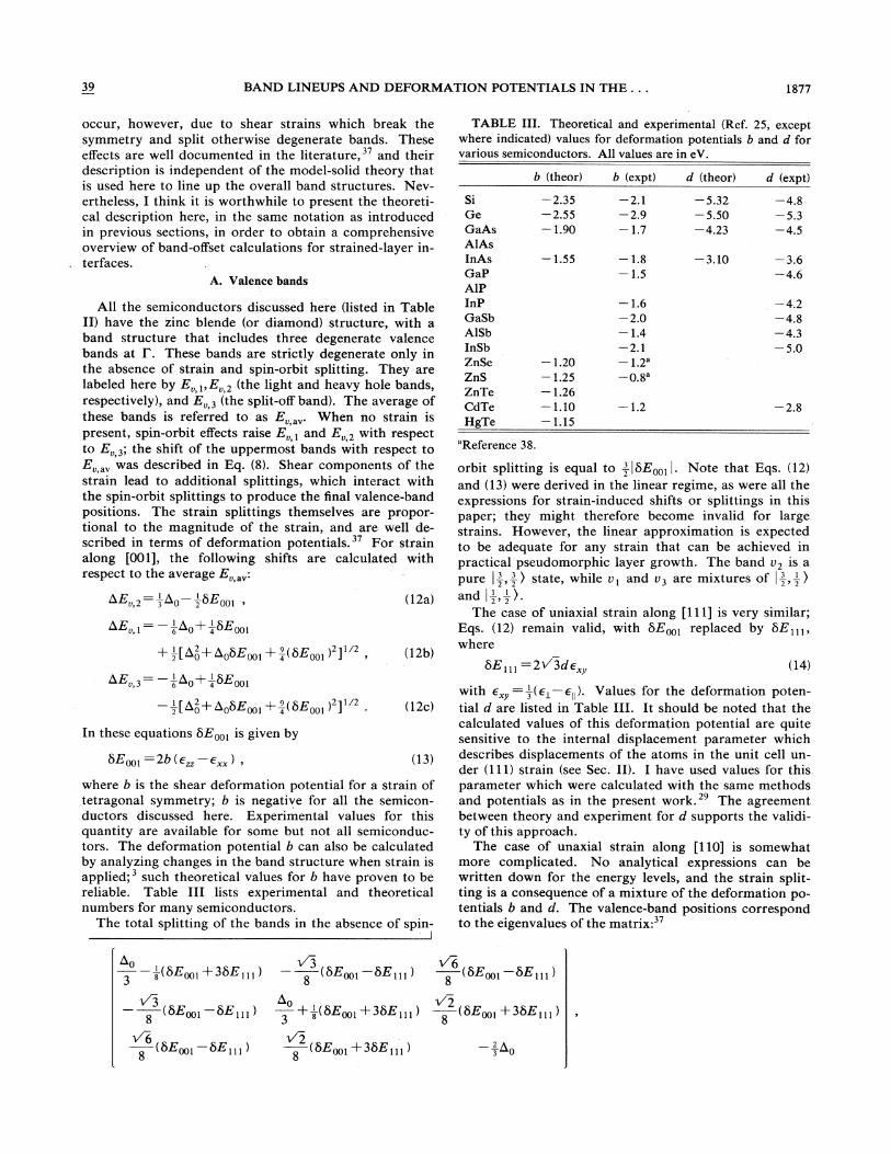
where b is the shear deformation potential for a strain oftetragonal symmetry; b is negative for all the semicon-ductors discussed here. Experimental values for thisquantity are available for some but not all semiconduc-tors. The deformation potential b can also be calculatedby analyzing changes in the band structure when strain isapplied; such theoretical values for b have proven to bereliable. Table III lists experimental and theoreticalnumbers for many semiconductors.
The total splitting of the bands in the absence of spin-I
occur, however, due to shear strains which break thesymmetry and split otherwise degenerate bands. Theseeffects are well documented in the literature, and theirdescription is independent of the model-solid theory thatis used here to line up the overall band structures. Nev-ertheless, I think it is worthwhile to present the theoreti-cal description here, in the same notation as introducedin previous sections, in order to obtain a comprehensiveoverview of band-offset calculations for strained-layer in-terfaces.
A. Valence bands
TABLE III. Theoretical and experimental (Ref. 25, exceptwhere indicated) values for deformation potentials b and d forvarious semiconductors. All values are in eV.
SiGeGaAsAlAsInAsGaPAlpInPGaSbAlsbInSbZnSeZnSZn TeCdTeHg Te
b (theor)
—2.35—2.55—1.90
—1.55
—1.20—1.25—1.26—1.10—1.15
b (expt)
—2.1—2.9—1.7
—1.8—1.5
—1.6—2.0—1.4—2.1—1.2'—0.8'
—1.2
d (theor)
—5.32—5.50—4.23
—3.10
d (expt)
—4.8—5.3—4.5
—3.6—4.6
—4.2—4.8—4.3—5.0
5E111=2+3«x (14)
with e„~=—,'(e~ —e~~). Values for the deformation poten-
tial d are listed in Table III. It should be noted that thecalculated values of this deformation potential are quitesensitive to the internal displacement parameter whichdescribes displacements of the atoms in the unit cell un-der (111) strain (see Sec. II). I have used values for thisparameter which were calculated with the same methodsand potentials as in the present work. The agreementbetween theory and experiment for d supports the validi-ty of this approach.
The case of unaxial strain along [110] is somewhatmore complicated. No analytical expressions can bewritten down for the energy levels, and the strain split-ting is a consequence of a mixture of the deformation po-tentials b and d. The valence-band positions correspondto the eigenvalues of the matrix:
'Reference 38.
orbit splitting is equal to —', ~5Eoo, ~. Note that Eqs. (12)and (13) were derived in the linear regime, as were all theexpressions for strain-induced shifts or splittings in thispaper; they might therefore become invalid for largestrains. However, the linear approximation is expectedto be adequate for any strain that can be achieved inpractical pseudomorphic layer growth. The band U2 is apure
~
—', , —', ) state, while v& and v3 are mixtures of g, —,' )
The case of uniaxial strain along [111]is very similar;Eqs. (12) remain valid, with 5Eoo, replaced by 5E», ,
where
v'3ooi
68
(5E001 5E111 )
6o +8 (5Eoo& +35E]] &
)
2 (5E+»+35E», )
6o v'33 8
—(5E001 +35E111) (5E001 5E111)8
6(5Eooi
2(5Eoo, +35E», )
2Q3
1878 CHRIS G. VAN de WALLE 39
where now
&Eooi =4b (e'xx (15a)
and
'6E~ ~~:( 4/&3 )dE& (15b)
Example. At this point we can go back to our exampleof (001) ZnS/ZnSe, and include the strain splitting of thevalence band in ZnS. Recalling that e =e
y=0.046 and
e„=—0.058, and using b = —1.25 from Table III, weobtain with Eq. (13): 5Eoo, =0.26 eV. Equations (12)then give
AE, 2= —0.11,AE, 1=+0.26,
AE, 3= —0. 16 .
Notice that b.E, , + b,E, z+ AE„3=0 (within the roundofferror), as appropriate for shifts expressed with respect tothe average. We see that the uppermost valence band(U&) in ZnS is 0.26 eV above E, ,"„. In ZnSe, the upper-most valence band is h0/3=0. 14 eV above E, ,",'. Wepreviously had: E, ,„=0.70 eV (higher in ZnSe). Thefinal valence-band offset becomes: AE, =0.70+0. 14—0, 26=0.58 eV. The lineups are shown in Fig. 2.
001 2 b,C 3 ll ZZ XX )
gE 100,010 1 6( )C 3 0 ZZ XX
(18a)
(18b)
The superscript 6 on =„ indicates which type ofconduction-band valley (at b, or at L) we are considering,while the superscript on AE, refers to the direction of theparticular conduction-band minimum. "„ is often denot-ed as E2 (see Ref. 40).
Next we consider conduction bands at L. (001) strainhas no effect now. Strain along [111]leads to
gE 111 2 LC u Xy
AE 111 111,111 2 LC 3 El Xy
Finally, strain along [110]yields
(19a)
(19b)
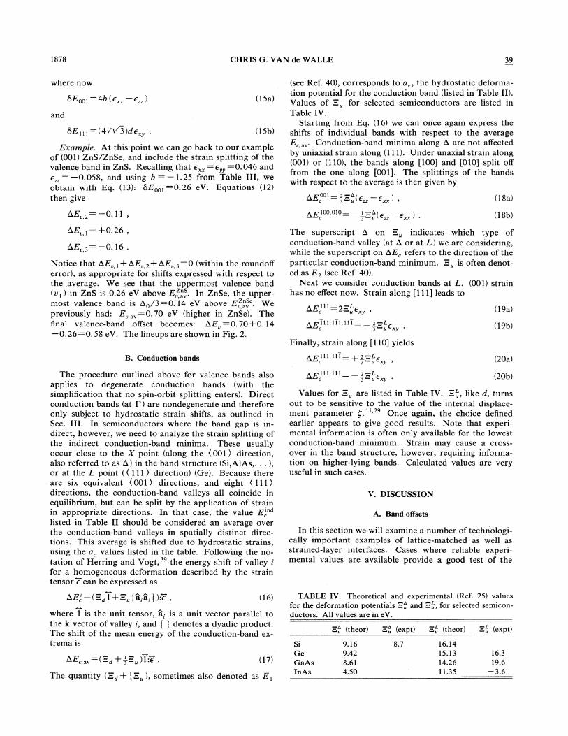
(see Ref. 40), corresponds to a„ the hydrostatic deforma-tion potential for the conduction band (listed in Table II).Values of:-„ for selected semiconductors are listed inTable IV.
Starting from Eq. (16) we can once again express theshifts of individual bands with respect to the averageE,„.Conduction-band minima along 6 are not affectedby uniaxial strain along (111). Under unaxial strain along(001) or (110), the bands along [100] and [010] split offfrom the one along [001]. The splittings of the bandswith respect to the average is then given by
B. Conduction bands gE111,111 + 2 —J ~C 3 u Xy (20a)
b E,' =(:-d1+:-„[a,a, I ):e, (16)
where 1 is the unit tensor, a, is a unit vector parallel tothe k vector of valley i, and [ ) denotes a dyadic product.The shift of the mean energy of the conduction-band ex-trema is
b,E, ,„=(:-d + —,':-„)1 7 . (17)
The quantity (:"d+—,':-„),sometimes also denoted as E,
The procedure outlined above for valence bands alsoapplies to degenerate conduction bands (with thesimplification that no spin-orbit splitting enters). Directconduction bands (at I ) are nondegenerate and thereforeonly subject to hydrostatic strain shifts, as outlined inSec. III. In semiconductors where the band gap is in-direct, however, we need to analyze the strain splitting ofthe indirect conduction-band minima. These usuallyoccur close to the X point (along the (001) direction,also referred to as 6, ) in the band structure (Si,AIAs, . . . ),or at the L point ((111)direction) (Ge). Because thereare six equivalent ( 001 ) directions, and eight ( 111)directions, the conduction-band valleys all coincide inequilibrium, but can be split by the application of strainin appropriate directions. In that case, the value E,'"listed in Table II should be considered an average overthe conduction-band valleys in spatially distinct direc-tions. This average is shifted due to hydrostatic strains,using the a, values listed in the table. Following the no-tation of Herring and Vogt, the energy shift of valley i'
for a homogeneous deformation described by the straintensor e can be expressed as
gE 111,111 2 -LC 3 lC Xy (20b)
Values for =„are listed in Table IV. :"„,like d, turnsout to be sensitive to the value of the internal displace-ment parameter g. " Once again, the choice definedearlier appears to give good results. Note that experi-mental information is often only available for the lowestconduction-band minimum. Strain may cause a cross-over in the band structure, however, requiring informa-tion on higher-lying bands. Calculated values are veryuseful in such cases.
V. DISCUSSION
A. Band offsets
In this section we will examine a number of technologi-cally important examples of lattice-matched as well asstrained-layer interfaces. Cases where reliable experi-mental values are available provide a good test of the
SiGeGaAsInAs
:"„(theor)
9.169.428.614.50
4,'expt)
8.7
:-„(theor)
16.1415.1314.2611.35
(expt)
16.319.6
—3.6
TABLE IV. Theoretical and experimental I,'Ref. 25) valuesfor the deformation potentials =„and:-„,for selected semicon-ductors. All values are in eV.
39 BAND LINEUPS AND DEFORMATION POTENTIALS IN THE. . . 1879
model. I will also attempt to show how the model theoryis useful for examining trends -and quickly analyzing awide variety of systems for specific applications.
As emphasized before, the model-solid theory wasdeveloped based on the results and insights provided byfull self-consistent interface calculations for a widevariety of systems. Many lineups derived from Table IIhave been compared with results obtained from full self-consistent interface calculations, where avail-
The results of the model are typicallywithin 0.2 eV of the fully self-consistent values, both forlattice-matched and strained-layer interfaces. Thistheoretical justification, along with favorable compar-isons with experiment, gives us confidence in the modeland values presented here.
In Sec. III we used the example of A1Sb/GaSb to illus-trate the derivation of offsets at lattice-matched inter-faces, and found AE, =0.47 eV. This value is very closeto the experimental value, 0.41+0.1 eV, obtained byGualtieri et al. from x-ray photoemission spectroscopy(XPS) measurements, and 0.45+0.08 eV, obtained byMenendez et al. with a light-scattering technique. "
Our other example was that of a ZnS/ZnSe (001) inter-face, which resulted in a very small conduction-bandoffset: AE, =0.03 eV. Because the model-solid theory isexpressed in terms of analytical formulas and tabulatedparameters, it lends itself easily to systematic studies ofband offsets for a variety of situations. For instance, inthe case of ZnS/ZnSe one might want to explore whethervariations in the strain (created by growth on differentsubstrates, or in free-standing superlattices with varjouslayer thicknesses) can lead to significant variations in theconduction-band offset, perhaps with the goal of develop-ing a device structure for which a sizable AE, is essential.In the case of ZnS/ZnSe, we find that the conduction-band offset is always small. This prediction wasconfirmed by experimental observations. Model-solidpredictions for other II-VI compound interfaces are dis-cussed in Ref. 41.
The list of cases where model-solid predictions agreewell with experiment is long and still growing. Verygood results were found for Si/Ge strained-layer inter-faces, as discussed in Ref. 9. Many lattice-matched junc-tions were discussed in Ref. 2. As an example, AE, forAlAs/GaAs is predicted to be 0.60 eV, and measured as0.45 —0.56 eV. For InAs/QaSb, the model predictsthe correct "broken gap" lineup, with the valence band ofGaSb above the conduction band of InAs. In the case ofCdTe/HgTe, the model solid favors the "large valence-band offset, " giving b,E, =0.24 eV (to be compared withthe x-ray photoemission value of b E, =0.35 eV).
Heterostructures are often based not only on pure ma-terials, but also on alloys. Varying the composition of analloy yields variations in the lattice constant, which arewell described by a linear interpolation such as in thevirtual-crystal approximation. This provides additionalfIexibility in tailoring the electronic properties of the sys-tem. To derive valence-band positions for an alloy, linearinterpolation between the pure materials is appropriate.This approach comes naturally in the context of superpo-sition of atoms in the model solid. When the constituent
+3x (1—x)[ —a,.( AC)+a;(BC)] Aa
ap(21)
where ba =a0( AC) a0(BC—).The linear-interpolation approximation may be less
adequate for conduction bands. In cases where largebowing is present (i.e., nonlinear behavior of the band gapas a function of alloy composition) I recommend the useof experimental values for the alloy band gap (includingbowing), in conjunction with model-solid values forvalence-band positions. Strain-induced shifts of thebands in the alloy can always be reliably predicted usinglinearly-interpolated values of deformation potentials.
Heterostructures based on combinations of GaAs,InAs, and InP are attracting increasing attention. As anexample, we consider lattice-matched Gap 47Inp 53Asgrown on a (100) InP substrate and find [with Eq. (21)]AE, =0.35 eV. Lang et al. ' applied the novel techniqueof admittance spectroscopy to this lattice-matched inter-face, leading to a valence-band offset of 0.35 eV. Skol-nick et al. found hE, =0.38 eV in an optical spectro-scopy study. Forrest et al. , using capacitance-voltage(C-V) techniques, obtained b,E, =0.36 eV. They also es-tablished that the relationship AE, =0.406E holds for aseries of lattice-matched InGaAsP/InP interfaces, span-ning the alloy range from Inp 53Gap 47As to pure InP. Fi-nally, Westland et al. reported optical absorption andphotolurninescence measurements on Gap 47Inp 43As/InPquantum wells, leading to AE, =0.325 eV. All thesevalues are in excellent agreement with the theoretical pre-diction.
Only one publication seems to give a somewhatdifferent result, namely the photoluminescence experi-ments of Sauer et al. on In053GaQ47As/InP quantumwells. They report AE, =0.406,E (and b,E,=0.60',E~ ), and consider this inconsistent with other ex-perimental offsets (quoted above). However, with theAE value used in their work we find AE, =0.25 eV.This is only 0.1 eV different from other values (and themodel theory), which seems to be within the error bar ofeven the most reliable experiments to date.
When the composition of the Ga In, As alloy ischanged, strains are introduced during pseudomorphicgrowth on a InP substrate. The band alignments in theresulting heterostructures have recently been analyzed byPeople, using our values for the lineups. Gershoniet al. have performed low-temperature photolumines-cence and photocur rent experiments on suchIn„GaI As/InP strained-layer superlattices. Goodagreement with their data is obtained if they assume avalence-band offset for the lattice-matched system of59% of the band-gap discontinuity; a 15%%uo variation in
materials are not lattice matched, one should actuallyalso consider a strain contribution, since in an alloyA B, „C [with lattice constant . a0 =xa0( AC)+(1—x)a0(BC)] one material is effectively expanded,whereas the other is compressed. For an energy level E, ,with deformation potentials a;, this leads to the followingexpression:
E (x)= xE ( AC)+(1 x)E—(BC)
1880 CHRIS G. VAN de WALLE 39
this value does not cause any appreciable change in thecalculated curves, however. With the AE„value used intheir paper, bE, =0.596E leads to AE, =0.37 eV forGaQ 47Inp 53As/InP, in very good agreement with the oth-er experiments, and with the theoretical value.
A word of caution is appropriate here: when experi-mental data for band offsets are expressed as a percentageof the band-gap discontinuity AE, it is important tocheck which values for the band gaps were used by theauthors. These values may be different from the ones list-ed in Table II, due to several reasons: different measure-ment temperature (values in Table II are for low tempera-tures), or bowing which causes a derivation from lineari-ty. To compare with the theory, one should use the AEvalue quoted in the experimental work to calculate hE,(in eV).
A closely related system is that of Alp 48Inp 52As/Gap 47InQ 53As, which was examined by People et al.using a C- V profiling technique. They found b E, =0.50eV, and AE„=0.20 eV. Using Eq. (21), we obtain withthe model-solid values, hE, =0.21 eV, in good agreementwith the experimental value. Rao et al. used C- Vprofiling to measure valence- and conduction-banddiscontinuities at the lattice-matched Gap»Inp 49P/GaAsinterface. They found AE, =0.24 eV. Our theoreticalvalue is 0.36 eV.
Smith and Mailhiot have recently proposed InAs/Gap 6Inp4Sb superlattices as novel infrared photodetec-tors. In their analysis, they assume that the valencebands of unstrained InSb and GaSb line up. From TableII we see that the theory predicts the valence band ofInSb to be higher in energy by 0.16 eV than the valenceband of GaSb (the spin-orbit splitting is similar in both).This actually implies that the predicted properties of thesuperlattices are better than for the band offset used bySmith and Mailhiot. Based on Table II, we predict avalue for E, ,„at a InAs/Gao 6In04Sb heterojunction of-0.48 eV. Note that this can lead to a "broken-gap"lineup of the type that occurs in InAs/GaSb, but alsothat strain-induced shifts and splittings of the bands canlead to widely different values for AE, .
B. Band-edge deformation potentials
The values for band-edge deformation potentials listedin Table II have already been used extensively in our pre-dictions of band offsets at strained-layer interfaces. Thegood agreement with experiment obtained in many testcases already provides an indication of the reliability ofthese values. I also pointed out that the model-solid de-formation potentials agree very well with values obtainedfrom fully self-consistent calculations that produce theactual displacement of the band edges due to an inhomo-geneous deformation of the crystal ~ It is interesting,however, to investigate the practical significance of thesevalues in their own right.
While values for the band-gap deformation potentialscan be directly compared with reliable experimental data,the individual band-edge deformation potentials a, anda, are much harder to obtain experimentally, and havebeen quite controversial. Measurements are indirect, and
require a significant amount of analysis and interpreta-tion, including some assumptions. Here I will only men-tion some of the recent results; a more detailed discussionis presented in Ref. 7.
In principle, the deformation potentials can be deter-rnined from mobility measurements on high-purity ma-terials. Only in GaAs does there seem to be a growingconsensus about the value for ~a, ~
determined in thisfashion, which is around 7 eV. ' The model-solid value isa, = —7. 17 eV.
A second class of measurements is based on the use oftransition-metal impurity levels as reference levels inband-structure lineups. This approach relies on the ob-servation that several substitutional transition metal im-purities give rise to deep levels that exhibit a universal be-havior, i.e., they can serve as reference lineups to line upband structures at heterojunctions. At this point intime, no rigorous theoretical justification exists for thisapproach, and no information is available about its gen-erality and accuracy. Based on its success for a numberof heterojunctions, however, it seems attractive to applythe approach to the deformation potential problem.Based on their own DLTS experiments, Nolte et aI.found a value of a, = —9.3 eV for GaAs, and —7.0 eVfor InP. They also derived a value of a, =2.4 eV for Si,based on other published work. In a similar approach,Samuelson and Nilsson used photoluminescence todetermine the hydrostatic pressure derivatives, and founda, = —7.7 eV in GaAs. All of these values are in reason-able agreement with the present first-principles calcula-tions.
A third class of measurements relies on the effect ofheavy doping on the lattice constant. A large concentra-tion of shallow donors, for instance, can lead to a volumechange which lowers the conduction band, and reducesthe total energy of the system. This effect has to com-pete, of course, with the increase in elastic energy; formu-las have been developed by Yokota. The change in lat-tice constant in general not only depends on this electron-ic effect, but also includes a "size effect" due to the pres-ence of a different type of atoms. A way of separatingthese effects was proposed in recent work by Cargillet al. , who used x-ray scattering to determine thechanges in lattice constant, and extended x-ray absorp-tion fine-structure (EXAFS) measurements to extract thesize effect. For Si, they found a, =3.3 eV, very close tothe theoretical value.
With regard to other theories, we can compare thevalues of band-edge deformation potentials listed in TableII with those obtained by Cardona and Christensenbased on a dielectric screening model. There appears tobe a remarkable difference between the values for thevalence-band deformation potentials: ours are all posi-tive, whereas those obtained by Cardona and Christensenare all negative. All these values are quite small in mag-nitude, however, so that the difference may not be verysignificant. The model-solid values show better agree-ment with the most recent experiments.
An important overall conclusion to be drawn fromTable II is that the valence-band deformation potentialsare small compared to the deformation potentials for the
39 BAND LINEUPS AND DEFORMATION POTENTIALS IN THE ~ ~ . 1881
direct gap; for direct-gap semiconductors, most of thevariation under strain occurs in the conduction band.
C. Pressure dependence of band offsets
The values in Table II allow the derivation of banddiscontinuities, including cases where strains are present.So far, we have only considered situations where thesestrains are built in, due to a lattice mismatch. The ap-proach can also be used, however, in the case of external-ly applied pressure. The investigation of heterojunctionsunder pressure is indeed becoming an important experi-mental tool.
Theoretical values for changes in band offsets atlattice-matched interfaces under applied hydrostatic pres-sure can be obtained by taking differences of the band-edge deformation potentials listed in Table II. When thisprocedure is applied to valence-band offsets, the resultingpressure derivative will be small because the individualnumbers for the valence bands are similar in magnitude.Since they are also subject to an error bar of +1 eV, therelative error will be rather large. For AlAs/GaAs weobtain from Table II: [1(bE, )]/[d InQ]=a, ' '—a, ' '= —1.31 eV. Self-consistent interface calcula-tions for this system under hydrostatic pressure pro-duced a value [d(EE„)]/[d InA]= —0.64 eV. We seethat the difference between model-solid theory and fullcalculations is well within the error bar. The result that[d(bE, )]/[d InQ] is small indicates that hE, remainsrather constant under pressure, an assumption essentialfor the interpretation of the experiments in Ref. 69.
Another very interesting case is that of InAs/Gasb,which has a so-called staggered lineup: the GaSb valenceband is higher in energy than the InAs conduction band.Investigators therefore often concentrate upon the mea-surement of the energy difference between these twobands. Claessen et al. used magneto-optical methodsto determine the change in energy separation betweenE,'" ' and E, ' under hydrostatic pressure, and foundd (E, ' E,'" ')/dP =——5.8 meV/kbar. From ananalysis of transport measurements on InAs/GaSb het-erostructures under hydrostatic pressure, Beerens et al. '
derived
d ( EGasb E inAs) /dP — 6 7 me V /GPa
= —6.7 meV/kbar .
Using the values from Table II, we find that
d(E ' E" ')/d InQ=(0. 7—9)—( —5.08)
=5.87 eV .
This value was confirmed by carrying out a full self-
consistent interface calculation, which agreed with themodel solid to within 0.3 eV. The theoretical values areexpressed as energy shifts per fractional volume change.In order to convert to energy shifts per unit pressure, onecan use the relationship P = —BAG/0, where B is thebulk modulus. B can quite easily be obtained from TableI, using the formula 8 =(c»+Zc,z)/3. This leads toB =580 kbar for InAs, and B =S78 kbar for GaSb. Wethus find d(E„' E,'" —')/dP = —10.1 meV/kbar. Theerror bar on the a, and a, values in Table II is +1 eV,which leads to an error bar of +3 meV on the value ofthe pressure derivative. Because of the error bar on thetheoretical (and presumably also on the experimental)value, the theoretical result is not inconsistent with theexperiments quoted above. However, the deviation mayindicate that other factors are playing a role in the exper-iment or its interpretation. One possible factor is uniaxi-al strain. The theoretical value is derived under the as-sumption that the strain is purely hydrostatic. In the ex-perimental situation, even if the applied stress is purelyhydrostatic, small uniaxial components may arise becauseof the anisotropy of the sample (e.g. , due to the differencein elastic constants between the two materials). Uniaxialstrain does not affect the InAs conduction band, but leadsto a splitting of the GaSb valence bands; this may reducethe observed rate of decrease of the band discontinuity.
UI. CONCLUSIONS
I have presented a theoretical model to calculate bandlineups at lattice-matched and strained-layer interfaces,and tabulated parameters to calculate band lineups for awide variety of semiconductors. The important effectsdue to strains in the layers were emphasized, andprescriptions for evaluating the strain components weregiven. These strains are determined by the lattice con-stants (i.e., choice of materials and alloy composition),the boundary conditions (i.e., choice of substrate), andthe thickness of the layers (in a free-standing superlat-tice). This provides wide fiexibility in the design of newheterostructures. The model-solid theory, developedbased on full self-consistent interface calculations, com-pares well with experiment in various reliable test cases.The model and values presented here therefore provide abasis for analysis and design of novel interface structures,as illustrated in many examples.
ACKNOWLEDGMENTS
Thanks are due to R. M. Martin for continued support,to D. J. Chadi for providing me with results of tight-binding calculations, and to J. Tersoff and W. A. Har-rison for helpful discussions and suggestions.
'Present address: Philips Laboratories, North American PhilipsCorporation, 345 Scarborough Road, BriarclifF Manor, NY10510.
G. C. Osbourn, J. Appl. Phys. 53, 1586 (1982).
~C. G. Van de Walle and R. M. Martin, Phys. Rev. B 35, 8154(1987).
C. G. Van de Walle and R. M. Martin, Phys. Rev. 8 34, 5621(1986).
1882 CHRIS G. VAN de WALLE 39
4See the discussion in Ref. 2.~J. Bardeen and W. Shockley, Phys. Rev. 80, 72 (1950).R. M. Martin and C. G. Van de Walle, Bull. Am. Phys. Soc. 30,
(3), 226 (1987).~C. G. Van de Walle and R. M. Martin (unpublished).~C. G. Van de Walle, Ph.D. dissertation, Stanford University,
1986.C. G. Van de Walle and R. M. Martin, J. Vac. Sci. Technol. B
4, 1055 (1986).L. C. Feldman, J. Bevk, B. A. Davidson, H.-J. Gossman, andJ. P. Mannaerts, Phys. Rev. Lett. 59, 664 (1987).L. Kleinman, Phys. Rev. 128, 2614 (1962).H. J. McSkimin, J. Appl. Phys. 24, 988 (1953);H. J. McSkiminand P. Andreatch, Jr., ibid. 35, 3312 (1964).C. W. Garland and K. C. Park, J. Appl. Phys. 33, 759 (1962).J. D. Wiley, in Semiconductors and Semimetals, edited by R.K. Willardson and A. C. Beer (Academic, New York, 1975),Vol. 10.
~~D. Gerlich, J. Appl. Phys. 34, 813 (1963).6W. F. Hoyle and R. J. Sladek, Phys. Rev. 8 11, 2933 (1975).F. S. Hickernell and W. R. Gayton, J. Appl. Phys. 37, 462(1966).
W. F. Boyle and R. J. Sladek, Phys. Rev. B 11, 1587 (1975).D. I. Bolef and M. Menes, J. Appl. Phys. 31, 1426 (1960).I. O. Bashkin and G. I. Pereseda, Fiz. Tverd. Tela (Leningrad)16, 3166 (1974) [Sov. Phys. —Solid State 16, 2058 (1975)].D. Berlincourt, H. Jaffe, and L. R. Shiozawa, Phys. Rev. 129,1009 (1963).R. B.Hall and J. D. Meakin, Thin Solid Films 63, 203 (1979).R. D. Greenough and S. B. Palmer, J. Phys. D 6, 587 (1973).R. I ~ Cottam and G. I. Saunders, J. Phys. Chem. Solids 36, 187(1975).
Landolt-Bornstein, Numerical Data and Functional Relation-ships in Science and Techology (Springer, New York, 1982),Group III, Vol. 17a-b.W. A. Harrison, E.A. Kraut, J. R. Waldrop, and R. W. Grant,Phys. Rev. B 18, 4402 (1978);R. M. Martin, J. Vac. Sci. Tech-nol. 17, 978 (1980).K. Kunc and R. M. Martin, Phys. Rev. B 24, 3445 (1981).P. Hohenberg and W. Kohn, Phys. Rev. 136, B864 (1964); W.Kohn and L. J. Sham, ibid. 140, A1133 (1965); exchange andcorrelation potentials are based on the data from D. M.Ceperley and B. J. Alder, Phys. Rev. Lett. 45, 566 (1980), asparametrized by J. Perdew and A. Zunger, Phys. Rev. B 23,5048 (1981).
See, e.g. , O. H. Nielsen and R. M. Martin, Phys. Rev. B 32,3792 (1985).G. B. Bachelet, D. R. Hamann, and M. Schliiter, Phys. Rev. B26, 4199 (1982).Although the absolute position of conduction bands suffersfrom large errors, changes in the bands such as those inducedby uniaxial or hydrostatic pressure are still reliably predicted.This feature will be used in calculating conduction-band de-formation potentials.
~Recent quasiparticle-energy calculations confirm this assess-ment; see M. S. Hybertsen and S. G. Louie, Phys. Rev. 8 34,5390 (1986).L. Kleinman, Phys. Rev. B 24, 7412 (1981).The electrostatic potential is, of course, only one part of thetotal potential in the solid; one also has to include the ex-change and correlation potential. Since the latter is not linearin the charge density, it cannot be obtained from a superposi-tion of atoms. However, this term is well defined in a bulkcalculation for the solid, since it is short range in nature (it is
the long-range terms which cause the arbitrariness in theelectrostatic potential). It can therefore be taken directlyfrom the bulk calculation, and only the electrostatic part ofthe potential should be obtained from the "model solid. "When strain is present, the exchange and correlation poten-tial can be obtained from the value for the unstrained materi-al, using the property that it is roughly proportional to p'It can therefore to a good approximation be considered tovary as 0Atomic configurations are listed in Ref. 2, and were obtainedfrom tight-binding calculations by D. J. Chadi (private com-munication). The sensitivity of the model-solid values to thechoice of configuration was discussed in Ref. 2.C. G. Van de Walle and R. M. Martin, Phys. Rev. 8 37, 4801(1988).
~F. H. Pollak and M. Cardona, Phys. Rev. 172, 816 (1968).~D. W. Langer, R. N. Euwema, K. Era, and T. Koda, Phys.
Rev. B 2, 4005 (1970).W. C. Herring and E. Vogt, Phys. Rev. 101, 944 (1956); I.Balslev, ibid. 143, 636 (1966).
4oE. O. Kane, Phys. Rev. 178, 1368 (1969).4'C. G. Van de Walle, K. Shahzad, and D. J. Olego, J. Vac. Sci.
Technol. B 6, 1350 (1988).C. G. Van de Walle and R. M. Martin, J. Vac. Sci. Technol. B5, 1225 (1987).
4~G. P. Gualtieri, R. G. Nuzzo, R. J. Malik, J. F. Walker, L. C.Feldman, W. A. Sunder, and G. P. Schwartz, J. Vac. Tech-nol. B 5, 1284 (1987).
44J. Menendez, A. Pinczuk, D. J. Werder, J. P. Valladares, T.H. Chiu, and W. T. Tsang, Solid State Commun. 61, 703(1987).
45K. Shahzad, D. J. Olego, and C. G. Van de Walle, Phys. Rev.8 38, 1417 (1988).
W. I. Wang and F. Stern, J. Vac. Sci. Technol. B 3, 1280(1985).
4~J. Batey and S. L. Wright, J. Appl. Phys. 59, 200 (1986).4 D. J. Wolford, in Proceedings of the 18th International Confer
ence on the Physics of Semiconductors, edited by O. Engstrom(World Scientific, Singapore, 1987), p. 1115.
4 S. P. Kowalczyk, J. T. Cheung, E. A. Kraut, and R. W. Grant,Phys. Rev. Lett. 56, 1605 (1986).
5OM. Cardona and N. E. Christensen, Phys. Rev. B 37, 1011(1988).
5~D. V. Lang, M. B.Panish, F. Capasso, J. Allam, R. A. Hamm,A. M. Sergent, and W. T. Tsang, Appl. Phys. Lett. 50, 736(1987).
5~M. S. Skolnick, P. R. Tapster, S. J. Bass, A. D. Pitt, A. Aps-ley, and S. P. Aldred, Semicond. Sci. Technol. 1, 29 (1986).S. R. Forrest, P. H. Schmidt, R. B. Wilson, and M. L.Kaplan, Appl. Phys. Lett. 45, 1199 (1984).
54D. J. Westland, A. M. Fox, A. C. Maciel, J. R. Ryan, M. D.Scott, J. I. Davies, and J. R. Riffat, Appl. Phys. Lett. 50, 839(1987).
55R. Sauer, T. D. Harris, and W. T. Tsang, Phys. Rev. B 34,9023 (1986).R. People, J. Appl. Phys. 62, 2551 (1987).D. Gershoni, J. M. Vandenberg, R. A. Hamm, H. Temkin,and M. B.Panish, Phys. Rev. B 36, 1320 (1987).
5~R. People, K. W. Wecht, K. Alavi, and A. Y. Cho, Appl.Phys. Lett. 43, 118 (1983).
59M. A. Rao, E. J. Caine, H. Kroemer, S. I. Long, and D. I. Ba-bic, J. Appl. Phys. 61, 643 (1987).D. L. Smith and C. Mailhiot, J. Appl. Phys. 62, 2545 (1987).W. Walukiewicz, H. E. Ruda, J. Lagowski, and H. C. Gatos,
39 BAND LINEUPS AND DEFORMATION POTENTIALS IN THE. . . 1883
Phys. Rev. B 32, 2645 (1985).M. J. Caldas, A. Fazzio, and A. Zunger, Appl. Phys. Lett. 45,671 (1984); J. M. Langer and H. Heinrich, Phys. Rev. Lett.55, 1414 (1985).D. D. Nolte, W. Walukiewicz, and E. E. Hailer, Phys. Rev.Lett. 59, 501 (1987).D. D. Nolte, W. Walukiewicz, and E. E. Hailer, Phys. Rev. B36, 9392 (1987).
65L. Samuelson and S. Nilsson, J. Lumin. 40441, 127 (1988).I. Yokota, J. Phys. Soc. Jpn. 18, 1487 (1964).G. S. Cargill III, J. Angilello, and K. L. Kavanagh, Phys. Rev.Lett. 6j., 1748 (1988).
M. Cardona and N. E. Christensen, Phys. Rev. B 35, 6182(1987);36, 2906(E) (1987).D. J. Wolford, T. F. Kuech, J. A. Bradley, M. Jaros, M. A.Gell, and D. Ninno, J. Vac. Sci. Technol. B 4, 1043 (1986); U.Venkateswaran, M. Chandrasekhar, H. R. Chandrasekhar, B.A. Vojak, F. A. Chambers, and J. M. Meese, Phys. Rev. B 33,8416 (1986).L. M. Claessen, J. C. Maan, M. Altarelli, P. Wyder, L. L.Chang, and L. Esaki, Phys. Rev. Lett. 57, 2556 (1986).J. Beerens, G. Gregoris, J. C. Portal, E. E. Mendez, L. L.Chang, and L. Esaki, Phys. Rev. B 36, 4742 (1988).