16
Auto Switch Guide Series C55 Consolidate your auto switches. Simplify your onsite inventory control. EMC-AutoSw-01 -UK Band mounting Rail mounting Tie-rod mounting Groove mounting
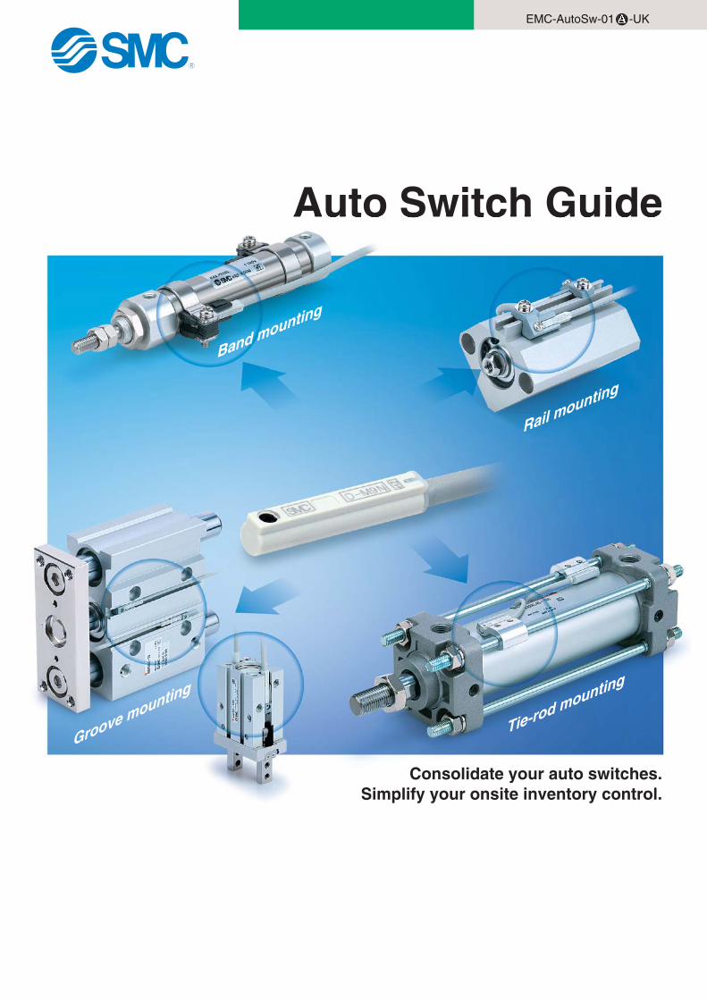
Auto Switch Guide
Series C55
Consolidate your auto switches.Simplify your onsite inventory control.
EMC-AutoSw-01 -UK
Band mounting
Rail mounting
Tie-rod mounting
Groove mounting
2
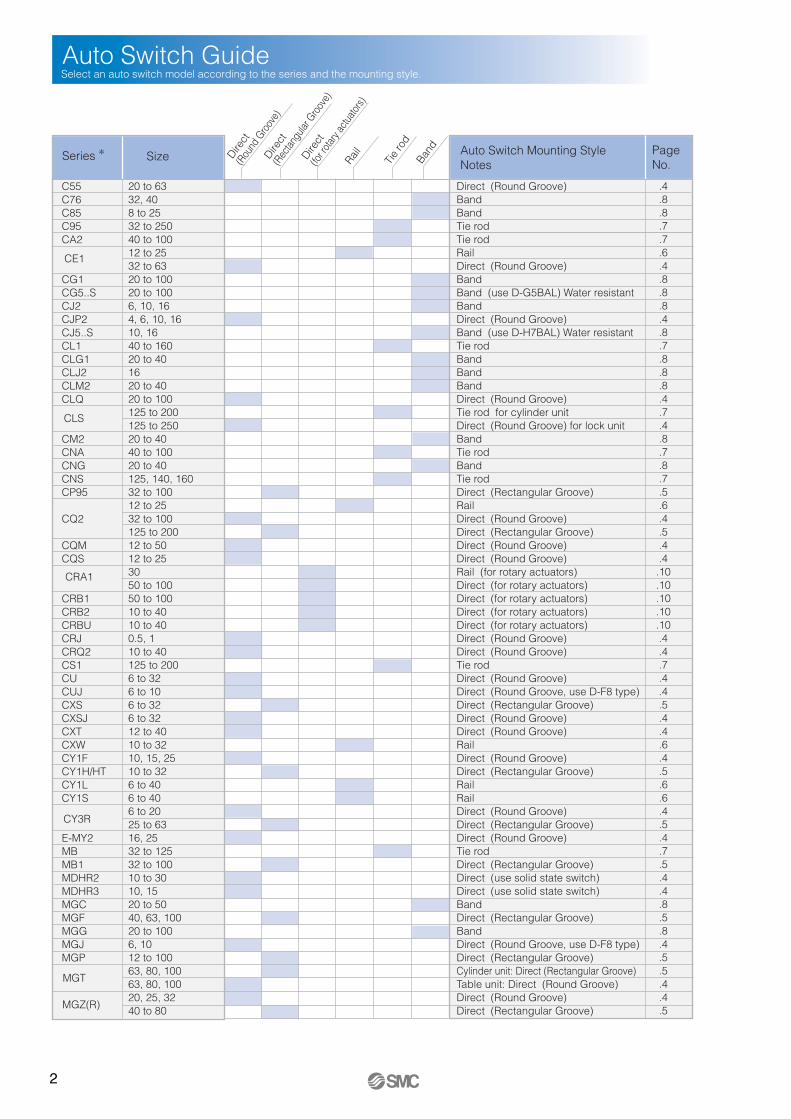
Auto Switch GuideSelect an auto switch model according to the series and the mounting style.
Page No.
Series ∗ Size Auto Switch Mounting StyleNotesTi
e ro
dBa
nd
RailDire
ct
(Rou
nd G
roov
e)Dire
ct
(Rec
tangu
lar G
roov
e)
Direct
(fo
r rota
ry ac
tuator
s)
CE1
CLS
CRA1
CY3R
MGT
MGZ(R)
C55C76C85C95CA2
CG1CG5..SCJ2CJP2CJ5..SCL1CLG1CLJ2CLM2CLQ
CM2CNACNGCNSCP95
CQ2
CQMCQS
CRB1CRB2CRBUCRJCRQ2CS1CUCUJCXSCXSJCXTCXWCY1FCY1H/HTCY1LCY1S
E-MY2MBMB1MDHR2MDHR3MGCMGFMGGMGJMGP
20 to 6332, 408 to 2532 to 25040 to 10012 to 2532 to 6320 to 10020 to 1006, 10, 164, 6, 10, 1610, 1640 to 16020 to 401620 to 4020 to 100125 to 200125 to 25020 to 4040 to 10020 to 40125, 140, 16032 to 10012 to 2532 to 100125 to 20012 to 5012 to 253050 to 10050 to 10010 to 4010 to 400.5, 110 to 40125 to 2006 to 326 to 106 to 326 to 3212 to 4010 to 3210, 15, 2510 to 326 to 406 to 406 to 2025 to 6316, 2532 to 12532 to 10010 to 3010, 1520 to 5040, 63, 10020 to 1006, 1012 to 10063, 80, 10063, 80, 10020, 25, 3240 to 80
Direct (Round Groove)Band Band Tie rod Tie rod Rail Direct (Round Groove) Band Band (use D-G5BAL) Water resistantBandDirect (Round Groove)Band (use D-H7BAL) Water resistantTie rod Band Band Band Direct (Round Groove)Tie rod for cylinder unitDirect (Round Groove) for lock unitBandTie rod Band Tie rod Direct (Rectangular Groove)Rail Direct (Round Groove)Direct (Rectangular Groove)Direct (Round Groove)Direct (Round Groove)Rail (for rotary actuators)Direct (for rotary actuators)Direct (for rotary actuators)Direct (for rotary actuators)Direct (for rotary actuators)Direct (Round Groove)Direct (Round Groove)Tie rod Direct (Round Groove)Direct (Round Groove, use D-F8 type)Direct (Rectangular Groove)Direct (Round Groove)Direct (Round Groove)Rail Direct (Round Groove)Direct (Rectangular Groove)Rail Rail Direct (Round Groove)Direct (Rectangular Groove)Direct (Round Groove)Tie rod Direct (Rectangular Groove)Direct (use solid state switch)Direct (use solid state switch)Band Direct (Rectangular Groove)Band Direct (Round Groove, use D-F8 type)Direct (Rectangular Groove)Cylinder unit: Direct (Rectangular Groove)Table unit: Direct (Round Groove)Direct (Round Groove)Direct (Rectangular Groove)
.4
.8
.8
.7
.7
.6
.4
.8
.8
.8
.4
.8
.7
.8
.8
.8
.4
.7
.4
.8
.7
.8
.7
.5
.6
.4
.5
.4
.4.10.10.10.10.10.4.4.7.4.4.5.4.4.6.4.5.6.6.4.5.4.7.5.4.4.8.5.8.4.5.5.4.4.5
3
Page No.
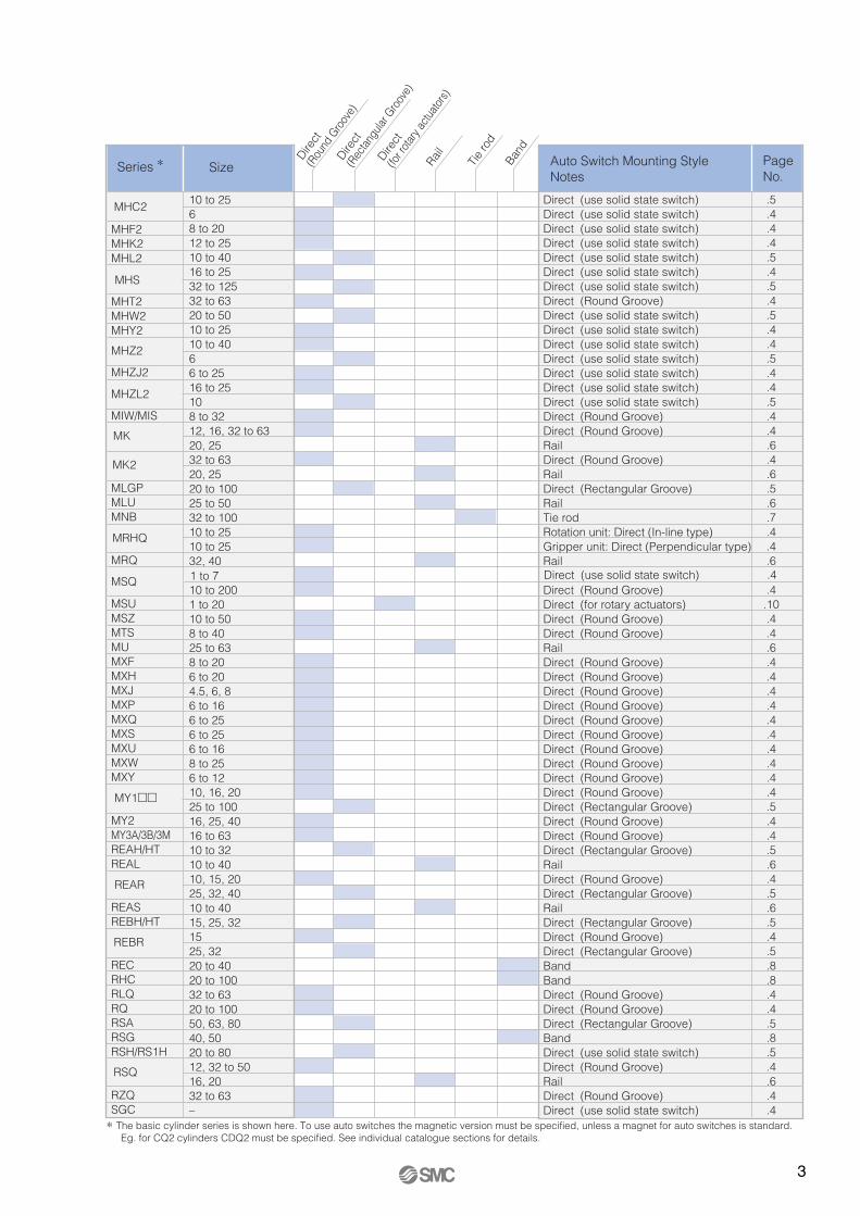
Series ∗ Size Auto Switch Mounting StyleNotes
Tie
rod
Band
RailDire
ct
(Rou
nd G
roov
e)Dire
ct
(Rec
tangu
lar G
roov
e)
Direct
(fo
r rota
ry ac
tuator
s)
MHC2
MHS
MRHQ
MY1��
REAR
REBR
∗ The basic cylinder series is shown here. To use auto switches the magnetic version must be specified, unless a magnet for auto switches is standard. Eg. for CQ2 cylinders CDQ2 must be specified. See individual catalogue sections for details.
RSQ
MK
MK2
MHF2MHK2MHL2
MHT2MHW2MHY2
MHZ2
MHZJ2
MHZL2
MIW/MIS
MLGPMLUMNB
MRQ
MSQ
MSUMSZMTSMUMXFMXHMXJMXPMXQMXSMXUMXWMXY
MY2MY3A/3B/3MREAH/HTREAL
REASREBH/HT
RECRHCRLQRQRSARSGRSH/RS1H
RZQSGC
10 to 2568 to 2012 to 2510 to 4016 to 2532 to 12532 to 6320 to 5010 to 2510 to 4066 to 2516 to 25108 to 3212, 16, 32 to 6320, 2532 to 6320, 2520 to 10025 to 5032 to 10010 to 2510 to 2532, 40
10 to 2001 to 2010 to 508 to 4025 to 638 to 206 to 204.5, 6, 86 to 166 to 256 to 256 to 168 to 256 to 1210, 16, 2025 to 10016, 25, 4016 to 6310 to 3210 to 4010, 15, 2025, 32, 4010 to 4015, 25, 321525, 3220 to 4020 to 10032 to 6320 to 10050, 63, 8040, 5020 to 8012, 32 to 5016, 2032 to 63–
Direct (use solid state switch)Direct (use solid state switch)Direct (use solid state switch)Direct (use solid state switch)Direct (use solid state switch)Direct (use solid state switch)Direct (use solid state switch)Direct (Round Groove)Direct (use solid state switch)Direct (use solid state switch)Direct (use solid state switch)Direct (use solid state switch)Direct (use solid state switch)Direct (use solid state switch)Direct (use solid state switch)Direct (Round Groove)Direct (Round Groove)RailDirect (Round Groove)Rail Direct (Rectangular Groove)Rail Tie rod Rotation unit: Direct (In-line type)Gripper unit: Direct (Perpendicular type)Rail
Direct (Round Groove)Direct (for rotary actuators)Direct (Round Groove)Direct (Round Groove)Rail Direct (Round Groove)Direct (Round Groove)Direct (Round Groove)Direct (Round Groove)Direct (Round Groove)Direct (Round Groove)Direct (Round Groove)Direct (Round Groove)Direct (Round Groove)Direct (Round Groove)Direct (Rectangular Groove)Direct (Round Groove)Direct (Round Groove)Direct (Rectangular Groove)Rail Direct (Round Groove)Direct (Rectangular Groove)Rail Direct (Rectangular Groove)Direct (Round Groove)Direct (Rectangular Groove)Band Band Direct (Round Groove)Direct (Round Groove)Direct (Rectangular Groove)Band Direct (use solid state switch)Direct (Round Groove)RailDirect (Round Groove)Direct (use solid state switch)
.5
.4
.4
.4
.5
.4
.5
.4
.5
.4
.4
.5
.4
.4
.5
.4
.4
.6
.4
.6
.5
.6
.7
.4
.4
.6
.4.10.4.4.6.4.4.4.4.4.4.4.4.4.4.5.4.4.5.6.4.5.6.5.4.5.8.8.4.4.5.8.5.4.6.4.4
1 to 7 Direct (use solid state switch) .4

4
D-F8�Short body type
Direct mounting styleRound groove
D-M9�
Auto switch
Solid state switch type
Description
Applicable Auto Switch/Short Body Type/Direct mounting
24 VDC3-wire (PNP)
24 VDC3-wire (NPN)
24 VDC(2-colour indication)
3-wire (PNP)24 VDC2-wire
D-F8BL D-F8PL D-F8NL
ApplicableSeries
• Lead wire length = 3 m, refer to page 11 for other lengths.
CUJMGJCRJ ∗MSQ (1~7) ∗
(∗) Also applicable to these models for short strokes.
Solid state switch type
Description
Applicable Auto Switch/Direct mounting
• Since there are other applicable auto switches than those listed, refer to pages 11 to 14 or SMC's Best Pneumatics catalogue for details.(∗) Only solid state switches can be used.(∗∗) Bracket BMY3-016 is also required.
24 VDC3-wire (PNP)
24 VDC3-wire (NPN)
24 VDC(2-colour indication)
3-wire (PNP)
Reed switch type
24 VDC2-wire
D-A93L D-M9PL D-M9NL D-M9PWL
D-M9PSAPC D-M9NSAPC D-M9PWSAPC
ApplicableSeries
• Lead wire length = 0.5 m, refer to page 14 for other lengths.
• Lead wire length = 3 m, refer to page 11 for other lengths.
Auto switch with pre-wired connector (M8-3pin).
C55CJP2CE1 (ø32~63)
CLQCLSCQ2 (ø32~100)
CQMCQSCRJ ∗CRQ2CUCXSJCXTCY1FCY3R (ø6~20)
E-MY2B ∗∗E-MY2C/H/HTMDHR2MDHR3MGTMGZ(R) (ø20~32) ∗∗MHC2 (ø6)
MHF2 ∗MHK2 ∗MHS (ø16~25) ∗MHT2MHY2 ∗MHZ2 (ø6,16~40) ∗MHZJ2 ∗MHZL2 (ø16~25) ∗
MIW/MIS ∗MK (ø12, 16, 32~ 63)
MK2 (ø32~63)
MRHQMSQ (1~7) ∗MSQ (10~200)
MSZMTSMXFMXHMXJMXPMXQMXSMXUMXWMXYMY1� (ø10~20)
MY2MY3 ∗∗REAR (ø10~20)
REBR (ø15)
RLQRQ,RSQ (ø12,32~50)
RZQSGC ∗
5
Solid state switch type
Description
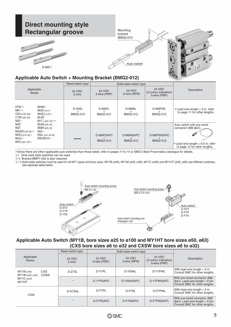
Applicable Auto Switch + Mounting Bracket (BMG2-012)
Direct mounting styleRectangular groove
D-M9�
• Since there are other applicable auto switches than those listed, refer to pages 11 to 14 or SMC's Best Pneumatics catalogue for details.(∗) Only solid state switches can be used.(∗∗) Bracket BMP1-032 is also required.(∗∗∗) Solid state switches must be used for all MY1 types and bore sizes. MY1B (ø40), MY1M (ø25, ø40), MY1C (ø40) and MY1HT (ø50, ø63) use different switches,
see separate table below.
24 VDC3-wire (PNP)
24 VDC3-wire (NPN)
24 VDC(2-colour indication)
3-wire (PNP)
Reed switch type
24 VDC2-wire
D-A93L+
BMG2-012
D-M9PL+
BMG2-012
D-M9NL+
BMG2-012
D-M9PWL+
BMG2-012
D-M9PSAPC+
BMG2-012
D-M9NSAPC+
BMG2-012
D-M9PWSAPC+
BMG2-012
ApplicableSeries
Auto switch
• Lead wire length = 0.5 m, refer to page 14 for other lengths.
• Lead wire length = 3 m, refer to page 11 for other lengths.
Auto switch with pre-wired connector (M8-3pin).
Mounting bracketBMG2-012
CP95 ∗∗MB1 ∗∗CQ2 (ø125~200)
CY3R (ø25~63) MGF ∗MGPMGT MGZ(R) (ø40~80) ∗∗MHC2 (ø10~25) ∗MHL2 ∗MHS (ø32~125) ∗
MHW2 ∗MHZ2 (ø10) ∗MHZL2 (ø10) ∗MLGPMY1� (ø25~100) ∗∗∗REAR (ø25~40)
REBR (ø25, 32)
RSA ∗RSQ (ø12, 32~63)
RSH/RS1H ∗
Solid state switch type
Description
Applicable Auto Switch (MY1B, bore sizes ø25 to ø100 and MY1HT bore sizes ø50, ø63) (CXS bore sizes ø6 to ø32 and CXSW bore sizes ø6 to ø32)
24 VDC3-wire (PNP)
24 VDC3-wire (NPN)
24 VDC(2-colour indication)
3-wire (PNP)
Reed switch type
24 VDC2-wire
D-Z73L D-Y7PL D-Y59AL D-Y7PWL
– D-Y7PSAPC D-Y59ASAPC D-Y7PWSAPC
D-A73HL D-F7PL D-F79L D-F7PWL
– D-F7PSAPC D-F79SAPC D-F7PWSAPC
ApplicableSeries
With lead wire length = 3 mConsult SMC for other lengths.
With pre-wired connector (M8-3pin). Lead wire length = 0.5mConsult SMC for other lengths.
With lead wire length = 3 mConsult SMC for other lengths.
With pre-wired connector (M8-3pin). Lead wire length = 0.5mConsult SMC for other lengths.
CXW
Auto switch mounting nut(Hexagon nut)
Auto switch mounting screw(M3 x 0.5 x 8 l)
Auto switchD-A73D-F7PD-F79
Auto switch mounting screwM2.5 x 4 l
Auto switchD-Z73D-Y7PD-Y59
MY1B (ø40)
MY1M (ø25, ø40)
MY1C (ø40)
MY1HT
CXSCXSW
6
Solid state switch type
Description
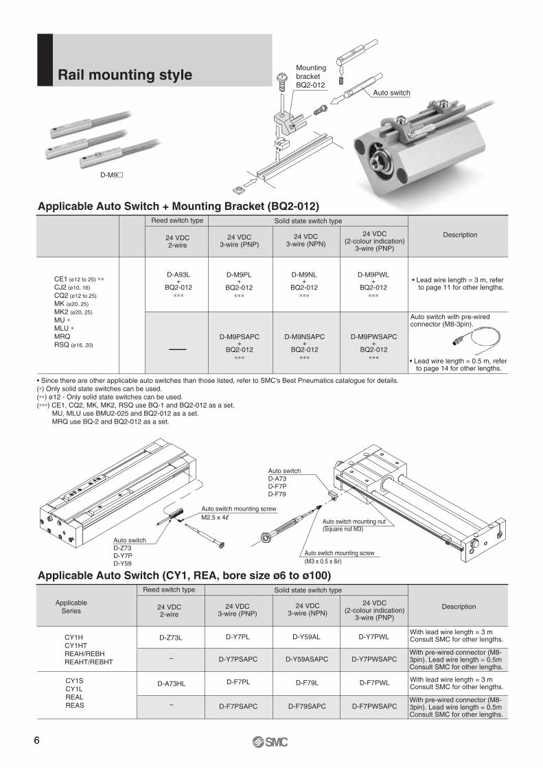
Applicable Auto Switch + Mounting Bracket (BQ2-012)
Rail mounting style
D-M9�
24 VDC3-wire (PNP)
24 VDC3-wire (NPN)
24 VDC(2-colour indication)
3-wire (PNP)
Reed switch type
24 VDC2-wire
Auto switch
• Lead wire length = 0.5 m, refer to page 14 for other lengths.
Mounting bracketBQ2-012
• Lead wire length = 3 m, refer to page 11 for other lengths.
Auto switch with pre-wired connector (M8-3pin).
Solid state switch type
Description
Applicable Auto Switch (CY1, REA, bore size ø6 to ø100)
24 VDC3-wire (PNP)
24 VDC3-wire (NPN)
24 VDC(2-colour indication)
3-wire (PNP)
Reed switch type
24 VDC2-wire
D-Z73L D-Y7PL D-Y59AL D-Y7PWL
– D-Y7PSAPC D-Y59ASAPC D-Y7PWSAPC
D-A73HL D-F7PL D-F79L D-F7PWL
– D-F7PSAPC D-F79SAPC D-F7PWSAPC
ApplicableSeries
CY1HCY1HTREAH/REBHREAHT/REBHT
With lead wire length = 3 mConsult SMC for other lengths.
With pre-wired connector (M8-3pin). Lead wire length = 0.5mConsult SMC for other lengths.
With lead wire length = 3 mConsult SMC for other lengths.
With pre-wired connector (M8-3pin). Lead wire length = 0.5mConsult SMC for other lengths.
CY1SCY1LREALREAS
• Since there are other applicable auto switches than those listed, refer to SMC's Best Pneumatics catalogue for details.(∗) Only solid state switches can be used.(∗∗) ø12 - Only solid state switches can be used.(∗∗∗) CE1, CQ2, MK, MK2, RSQ use BQ-1 and BQ2-012 as a set. MU, MLU use BMU2-025 and BQ2-012 as a set. MRQ use BQ-2 and BQ2-012 as a set.
D-A93L+
BQ2-012∗∗∗
D-M9PL+
BQ2-012∗∗∗
D-M9NL+
BQ2-012∗∗∗
D-M9PWL+
BQ2-012∗∗∗
D-M9PSAPC+
BQ2-012∗∗∗
D-M9NSAPC+
BQ2-012∗∗∗
D-M9PWSAPC+
BQ2-012∗∗∗
CE1 (ø12 to 25) ∗∗CJ2 (ø10, 16)
CQ2 (ø12 to 25)
MK (ø20, 25) MK2 (ø20, 25)
MU ∗MLU ∗MRQRSQ (ø16, 20)
Auto switch mounting nut(Square nut M3)
Auto switch mounting screw(M3 x 0.5 x 8 l)
Auto switchD-A73D-F7PD-F79
Auto switch mounting screwM2.5 x 4 l
Auto switchD-Z73D-Y7PD-Y59
7
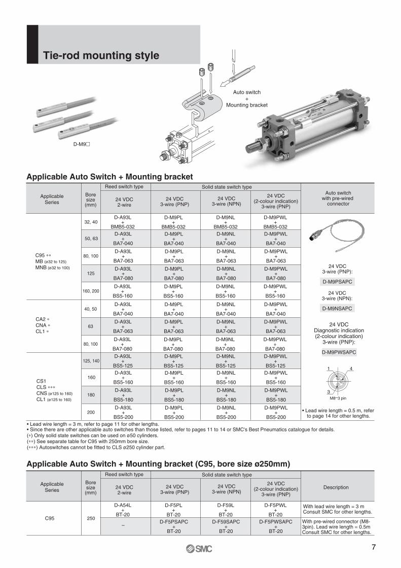
Boresize(mm)
Solid state switch typeAuto switch
with pre-wired connector
24 VDC3-wire (PNP):
D-M9PSAPC
Applicable Auto Switch + Mounting bracket
Tie-rod mounting style
D-M9�
• Lead wire length = 3 m, refer to page 11 for other lengths. • Since there are other applicable auto switches than those listed, refer to pages 11 to 14 or SMC's Best Pneumatics catalogue for details.(∗) Only solid state switches can be used on ø50 cylinders.(∗∗) See separate table for C95 with 250mm bore size.(∗∗∗) Autoswitches cannot be fitted to CLS ø250 cylinder part.
24 VDC3-wire (PNP)
24 VDC3-wire (NPN)
24 VDC(2-colour indication)
3-wire (PNP)
Reed switch type
24 VDC2-wire
D-A93L+
BMB5-03232, 40
D-M9PL+
BMB5-032
D-M9NL+
BMB5-032
D-M9PWL+
BMB5-032D-A93L
+BA7-040
50, 63D-M9PL
+BA7-040
D-M9NL+
BA7-040
D-M9PWL+
BA7-040
D-A93L+
BA7-06380, 100
D-M9PL+
BA7-063
D-M9NL+
BA7-063
D-M9PWL+
BA7-063
D-A93L+
BA7-080125
D-M9PL+
BA7-080
D-M9NL+
BA7-080
D-M9PWL+
BA7-080
D-A93L+
BS5-160160, 200
D-M9PL+
BS5-160
D-M9NL+
BS5-160
D-M9PWL+
BS5-160
ApplicableSeries
Auto switch+
Mounting bracket
D-A93L+
BA7-04040, 50
D-M9PL+
BA7-040
D-M9NL+
BA7-040
D-M9PWL+
BA7-040
D-A93L+
BA7-06363
D-M9PL+
BA7-063
D-M9NL+
BA7-063
D-M9PWL+
BA7-063
D-A93L+
BA7-08080, 100
D-M9PL+
BA7-080
D-M9NL+
BA7-080
D-M9PWL+
BA7-080
D-A93L+
BS5-125125, 140
D-M9PL+
BS5-125
D-M9NL+
BS5-125
D-M9PWL+
BS5-125D-A93L
+BS5-160
160D-M9PL
+BS5-160
D-M9NL+
BS5-160
D-M9PWL+
BS5-160
D-A93L+
BS5-180180
D-M9PL+
BS5-180
D-M9NL+
BS5-180
D-M9PWL+
BS5-180
D-A93L+
BS5-200200
D-M9PL+
BS5-200
D-M9NL+
BS5-200
D-M9PWL+
BS5-200
24 VDC3-wire (NPN):
D-M9NSAPC
24 VDCDiagnostic indication(2-colour indication)
3-wire (PNP):
D-M9PWSAPC
M8–3 pin
1 4
3
• Lead wire length = 0.5 m, refer to page 14 for other lengths.
Boresize(mm)
Solid state switch type
Description
Applicable Auto Switch + Mounting bracket (C95, bore size ø250mm)
24 VDC3-wire (PNP)
24 VDC3-wire (NPN)
24 VDC(2-colour indication)
3-wire (PNP)
Reed switch type
24 VDC2-wire
D-A54L+
BT-20250
D-F5PL+
BT-20
D-F59L+
BT-20
D-F5PWL+
BT-20
–D-F5PSAPC
+BT-20
D-F59SAPC+
BT-20
D-F5PWSAPC+
BT-20
ApplicableSeries
C95
With lead wire length = 3 mConsult SMC for other lengths.
With pre-wired connector (M8-3pin). Lead wire length = 0.5mConsult SMC for other lengths.
C95 ∗∗MB (ø32 to 125)
MNB (ø32 to 100)
CA2 ∗CNA ∗CL1 ∗
CS1CLS ∗∗∗CNS (ø125 to 160)
CL1 (ø125 to 160)
8
NBA-088S
NBA-106S
BGS1-032S
BAF-04S
BAF-05S
BAF-06S
BAF-08S
BAF-10S
Auto switchmodel
Mounting bracket no.
D-G5BAL
ø20 ø25 ø32 ø40 ø50 ø63 ø80 ø100
D-A93L+
BJ3-1 + BMA2-04040
D-M9PL+
BJ3-1 + BMA2-040
D-M9NL+
BJ3-1 + BMA2-040
D-M9PWL+
BJ3-1 + BMA2-040
D-A93L+
BJ3-1 + BMA2-05050
D-M9PL+
BJ3-1 + BMA2-050
D-M9NL+
BJ3-1 + BMA2-050
D-M9PWL+
BJ3-1 + BMA2-050
D-A93L+
BJ3-1 + BMA2-06363
D-M9PL+
BJ3-1 + BMA2-063
D-M9NL+
BJ3-1 + BMA2-063
D-M9PWL+
BJ3-1 + BMA2-063
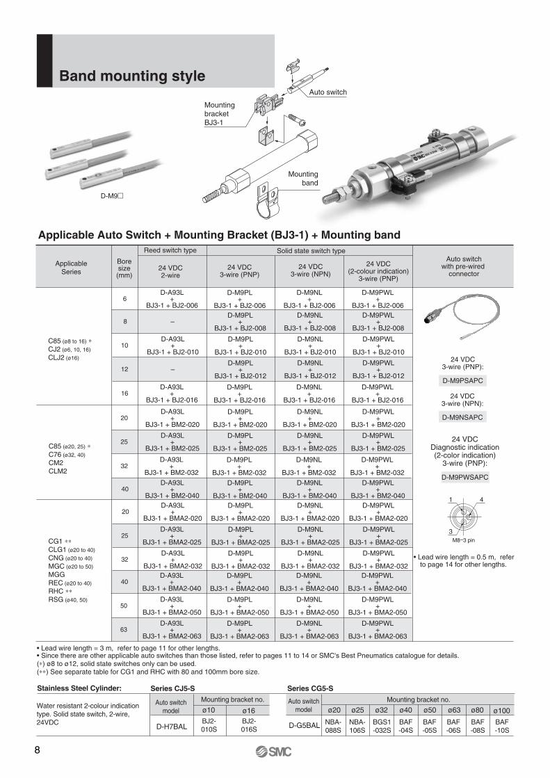
Boresize(mm)
Solid state switch typeAuto switch
with pre-wired connector
24 VDC3-wire (PNP):
D-M9PSAPC
Applicable Auto Switch + Mounting Bracket (BJ3-1) + Mounting band
Band mounting style
D-M9�
• Lead wire length = 3 m, refer to page 11 for other lengths. • Since there are other applicable auto switches than those listed, refer to pages 11 to 14 or SMC's Best Pneumatics catalogue for details.(∗) ø8 to ø12, solid state switches only can be used.(∗∗) See separate table for CG1 and RHC with 80 and 100mm bore size.
24 VDC3-wire (PNP)
24 VDC3-wire (NPN)
24 VDC(2-colour indication)
3-wire (PNP)
Reed switch type
24 VDC2-wire
D-A93L+
BJ3-1 + BJ2-0066
D-M9PL+
BJ3-1 + BJ2-006
D-M9NL+
BJ3-1 + BJ2-006
D-M9PWL+
BJ3-1 + BJ2-006
–8D-M9PL
+BJ3-1 + BJ2-008
D-M9NL+
BJ3-1 + BJ2-008
D-M9PWL+
BJ3-1 + BJ2-008
D-A93L+
BJ3-1 + BJ2-01010
D-M9PL+
BJ3-1 + BJ2-010
D-M9NL+
BJ3-1 + BJ2-010
D-M9PWL+
BJ3-1 + BJ2-010
–12D-M9PL
+BJ3-1 + BJ2-012
D-M9NL+
BJ3-1 + BJ2-012
D-M9PWL+
BJ3-1 + BJ2-012
D-A93L+
BJ3-1 + BJ2-01616
D-M9PL+
BJ3-1 + BJ2-016
D-M9NL+
BJ3-1 + BJ2-016
D-M9PWL+
BJ3-1 + BJ2-016
ApplicableSeries
Auto switch
D-A93L+
BJ3-1 + BM2-02020
D-M9PL+
BJ3-1 + BM2-020
D-M9NL+
BJ3-1 + BM2-020
D-M9PWL+
BJ3-1 + BM2-020
D-A93L+
BJ3-1 + BM2-02525
D-M9PL+
BJ3-1 + BM2-025
D-M9NL+
BJ3-1 + BM2-025
D-M9PWL+
BJ3-1 + BM2-025
D-A93L+
BJ3-1 + BM2-03232
D-M9PL+
BJ3-1 + BM2-032
D-M9NL+
BJ3-1 + BM2-032
D-M9PWL+
BJ3-1 + BM2-032
D-A93L+
BJ3-1 + BM2-04040
D-M9PL+
BJ3-1 + BM2-040
D-M9NL+
BJ3-1 + BM2-040
D-M9PWL+
BJ3-1 + BM2-040D-A93L
+BJ3-1 + BMA2-020
20D-M9PL
+BJ3-1 + BMA2-020
D-M9NL+
BJ3-1 + BMA2-020
D-M9PWL+
BJ3-1 + BMA2-020
D-A93L+
BJ3-1 + BMA2-02525
D-M9PL+
BJ3-1 + BMA2-025
D-M9NL+
BJ3-1 + BMA2-025
D-M9PWL+
BJ3-1 + BMA2-025
D-A93L+
BJ3-1 + BMA2-03232
D-M9PL+
BJ3-1 + BMA2-032
D-M9NL+
BJ3-1 + BMA2-032
D-M9PWL+
BJ3-1 + BMA2-032
24 VDC3-wire (NPN):
D-M9NSAPC
24 VDCDiagnostic indication(2-color indication)
3-wire (PNP):
D-M9PWSAPC
M8–3 pin
1 4
3
• Lead wire length = 0.5 m, refer to page 14 for other lengths.
Mounting bracketBJ3-1
Mountingband
Mounting bracket no.
BJ2-010S
BJ2-016S
ø10 ø16Auto switch
model
D-H7BAL
Stainless Steel Cylinder: Series CJ5-S Series CG5-S
Water resistant 2-colour indication type. Solid state switch, 2-wire, 24VDC
C85 (ø8 to 16) ∗CJ2 (ø6, 10, 16)
CLJ2 (ø16)
C85 (ø20, 25) ∗C76 (ø32, 40)
CM2CLM2
CG1 ∗∗CLG1 (ø20 to 40)
CNG (ø20 to 40)
MGC (ø20 to 50)
MGGREC (ø20 to 40)
RHC ∗∗RSG (ø40, 50)
9
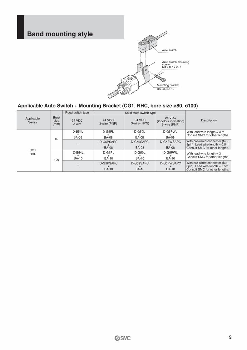
Boresize(mm)
Solid state switch type
Description
Applicable Auto Switch + Mounting Bracket (CG1, RHC, bore size ø80, ø100)
24 VDC3-wire (PNP)
24 VDC3-wire (NPN)
24 VDC(2-colour indication)
3-wire (PNP)
Reed switch type
24 VDC2-wire
D-B54L+
BA-0880
D-G5PL+
BA-08
D-G59L+
BA-08
D-G5PWL+
BA-08
–D-G5PSAPC
+BA-08
D-G59SAPC+
BA-08
D-G5PWSAPC+
BA-08
D-B54L+
BA-10100
D-G5PL+
BA-10
D-G59L+
BA-10
D-G5PWL+
BA-10
– D-G5PSAPC+
BA-10
D-G59SAPC+
BA-10
D-G5PWSAPC+
BA-10
ApplicableSeries
CG1RHC
With lead wire length = 3 mConsult SMC for other lengths.
With pre-wired connector (M8-3pin). Lead wire length = 0.5mConsult SMC for other lengths.
With lead wire length = 3 mConsult SMC for other lengths.
With pre-wired connector (M8-3pin). Lead wire length = 0.5mConsult SMC for other lengths.
Auto switch
Auto switch mounting screwM4 x 0.7 x 22 l
Mounting bracketBA-08, BA-10
Band mounting style
10
D-S7P1L+
D-S7P2L
D-S791L+
D-S792L
—D-S7P1SAPC
+D-S7P2SAPC
D-S791SAPC+
D-S792SAPC • Lead wire length = 0.5 m, consult SMC for other lengths.
• Lead wire length = 3 m, consult SMC for other lengths.
Auto switch with pre-wired connector (M8-3pin).
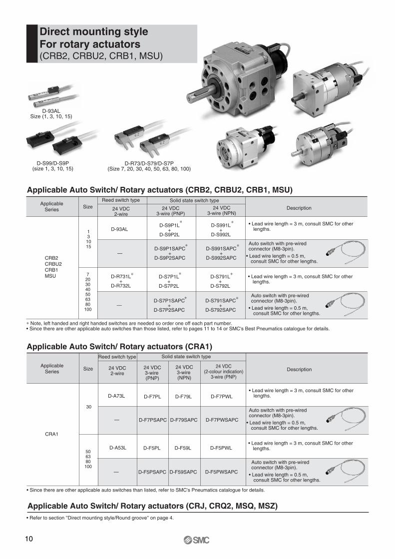
Applicable Auto Switch/ Rotary actuators (CRB2, CRBU2, CRB1, MSU)
D-93ALSize (1, 3, 10, 15)
D-R73/D-S79/D-S7P(Size 7, 20, 30, 40, 50, 63, 80, 100)
D-S99/D-S9P(size 1, 3, 10, 15)
Direct mounting styleFor rotary actuators(CRB2, CRBU2, CRB1, MSU)
SizeSolid state switch type
∗ Note, left handed and right handed switches are needed so order one off each part number.• Since there are other applicable auto switches than those listed, refer to pages 11 to 14 or SMC's Best Pneumatics catalogue for details.
24 VDC3-wire (PNP)
24 VDC3-wire (NPN)
Reed switch type
24 VDC2-wire
D-93ALD-S9P1L
+D-S9P2L
D-S991L+
D-S992L131015
ApplicableSeries
CRB2CRBU2CRB1MSU 7
203040506380100
—D-S9P1SAPC
+D-S9P2SAPC
D-S991SAPC+
D-S992SAPC
Description
• Lead wire length = 0.5 m, consult SMC for other lengths.
• Lead wire length = 3 m, consult SMC for other lengths.
Auto switch with pre-wired connector (M8-3pin).
∗ ∗
∗∗
D-R731L+
D-R732L
∗ ∗
∗∗
∗
Applicable Auto Switch/ Rotary actuators (CRA1)
D-F5PL D-F59L
— D-F5PSAPC D-F59SAPC • Lead wire length = 0.5 m, consult SMC for other lengths.
• Lead wire length = 3 m, consult SMC for other lengths.
Auto switch with pre-wired connector (M8-3pin).
Size
Solid state switch type
• Since there are other applicable auto switches than listed, refer to SMC's Pneumatics catalogue for details.
24 VDC3-wire (PNP)
24 VDC3-wire (NPN)
Reed switch type
24 VDC2-wire
D-A73L D-F7PL D-F79L
30
ApplicableSeries
CRA1
506380100
— D-F7PSAPC D-F79SAPC
Description
• Lead wire length = 0.5 m, consult SMC for other lengths.
• Lead wire length = 3 m, consult SMC for other lengths.
Auto switch with pre-wired connector (M8-3pin).
D-A53L
24 VDC(2-colour indication)
3-wire (PNP)
D-F5PWL
D-F5PWSAPC
D-F7PWL
D-F7PWSAPC
Applicable Auto Switch/ Rotary actuators (CRJ, CRQ2, MSQ, MSZ)• Refer to section ''Direct mounting style/Round groove'' on page 4.
11
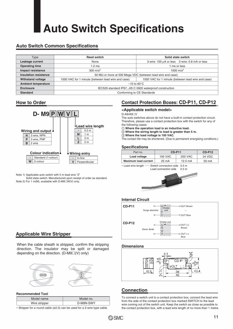
Auto Switch SpecificationsAuto Switch Common Specifications
Type
Leakage current
Operating time
Impact resistance
Insulation resistance
Withstand voltage
Ambient temperature
Enclosure
Standard
Reed switch
None
1.2 ms
300 m/s2
50 MΩ or more at 500 Mega VDC (between lead wire and case)
–10 to 60°CIEC529 standard IP67, JIS C 0920 waterproof construction
Conforming to CE Standards
Solid state switch
3-wire: 100 μA or less 2-wire: 0.8 mA or less
1 ms or less
1000 m/s2
1000 VAC for 1 minute (between lead wire and case) 1000 VAC for 1 minute (between lead wire and case)
How to Order
LM
0.5 m
3 m1 m
5 mZ
-
Lead wire length
LD- M9 P
Contact Protection Boxes: CD-P11, CD-P12
D-A9/A9�VThe auto switches above do not have a built-in contact protection circuit.Therefore, please use a contact protection box with the switch for any of the following cases:� Where the operation load is an inductive load.� Where the wiring length to load is greater than 5 m. � Where the load voltage is 100 VAC.The contact life may be shortened. (Due to permanent energising conditions.)
Specifications
Internal Circuit
Dimensions
Connection
∗ Lead wire length Switch connection side 0.5 m Load connection side 0.5 m
Part no.
Load voltage
Maximum load current
CD-P11
CD-P11
100 VAC
25 mA
200 VAC
12.5 mA
CD-P12
24 VDC
50 mA
To connect a switch unit to a contact protection box, connect the lead wire from the side of the contact protection box marked SWITCH to the leadwire coming out of the switch unit. Keep the switch as close as possible to the contact protection box, with a lead wire length of no more than 1 metre.
CD-P12
Surge absorberChoke
coil
OUT Brown
OUT Blue
OUT (+)Brown
OUT (–)Blue
Choke coil
Zener diode
Note 1) Applicable auto switch with 5 m lead wire “Z” Solid state switch: Manufactured upon receipt of order as standard.Note 2) For 1 m(M), available with D-M9�W(V) only.
<Applicable switch model>
When the cable sheath is stripped, confirm the stripping direction. The insulator may be split or damaged depending on the direction. (D-M9�(V) only)
Model no.D-M9N-SWY
Model nameWire stripper
∗ Stripper for a round cable (ø2.0) can be used for a 2-wire type cable.
Recommended Tool
Applicable Wire Stripper
W V
BP
3 wire, NPN
2 wire3 wire, PNP
N
Wiring and output
WStandard (1-colour)2-colour
-
Colour indication
VIn-linePerpendicular
-
Wiring entry
12
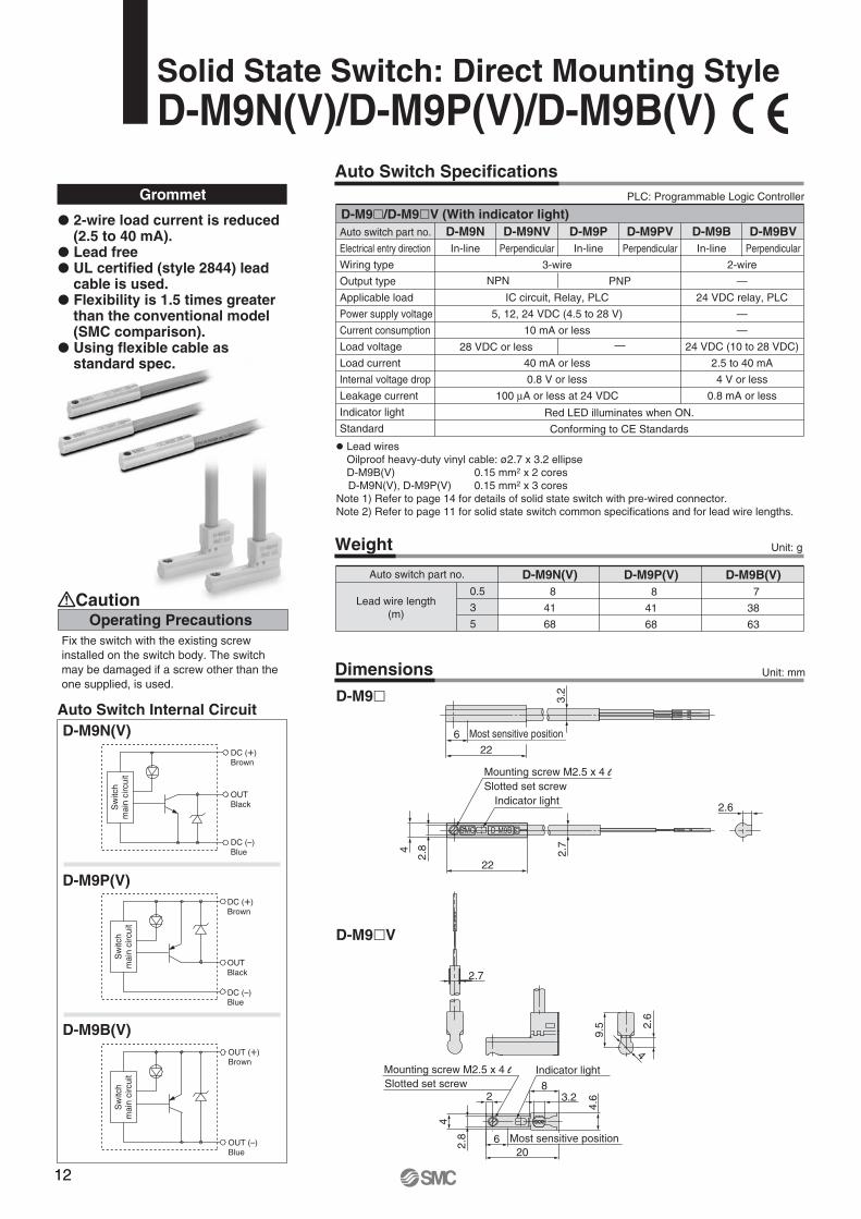
Solid State Switch: Direct Mounting StyleD-M9N(V)/D-M9P(V)/D-M9B(V)
Auto Switch Internal CircuitD-M9N(V)
D-M9B(V)
D-M9P(V)
Auto Switch Specifications
Weight
Auto switch part no.
0.5
3
5
D-M9N(V) 8
41
68
D-M9P(V) 8
41
68
D-M9B(V) 7
38
63
Unit: g
Lead wire length(m)
Grommet PLC: Programmable Logic Controller
Auto switch part no.
Electrical entry direction
Wiring type
Output type
Applicable load
Power supply voltage
Current consumption
Load voltage
Load current
Internal voltage drop
Leakage current
Indicator light
Standard
D-M9NVD-M9N D-M9B D-M9BV
2-wire
—
24 VDC relay, PLC
—
—
24 VDC (10 to 28 VDC)
2.5 to 40 mA
4 V or less
0.8 mA or less
D-M9PVD-M9P
Red LED illuminates when ON.
Conforming to CE Standards
3-wire
IC circuit, Relay, PLC
5, 12, 24 VDC (4.5 to 28 V)
10 mA or less
40 mA or less
0.8 V or less
100 μA or less at 24 VDC
In-line Perpendicular In-line Perpendicular In-line Perpendicular
NPN PNP
28 VDC or less —
D-M9�/D-M9�V (With indicator light)
� Lead wires Oilproof heavy-duty vinyl cable: ø2.7 x 3.2 ellipse D-M9B(V) 0.15 mm2 x 2 cores D-M9N(V), D-M9P(V) 0.15 mm2 x 3 coresNote 1) Refer to page 14 for details of solid state switch with pre-wired connector.Note 2) Refer to page 11 for solid state switch common specifications and for lead wire lengths.
Dimensions
D-M9�
D-M9�V
Mounting screw M2.5 x 4 lSlotted set screw
Indicator light
2.7
22
2.6
4
2.8
4
2.6
9.5
2.7
4.62
20
Mounting screw M2.5 x 4 l
2.8
83.2
4
6
Indicator lightSlotted set screw
Most sensitive position
� 2-wire load current is reduced (2.5 to 40 mA).
� Lead free� UL certified (style 2844) lead
cable is used.� Flexibility is 1.5 times greater
than the conventional model (SMC comparison).
� Using flexible cable as standard spec.
Operating PrecautionsCaution
Fix the switch with the existing screw installed on the switch body. The switch may be damaged if a screw other than the one supplied, is used.
Unit: mm
Sw
itch
mai
n ci
rcui
tS
witc
h m
ain
circ
uit
Sw
itch
mai
n ci
rcui
t
OUTBlack
DC (+)Brown
DC (–)Blue
OUTBlack
DC (+)Brown
DC (–)Blue
OUT (+)Brown
OUT (–)Blue
22
3.2
6 Most sensitive position
13
Auto Switch Specifications
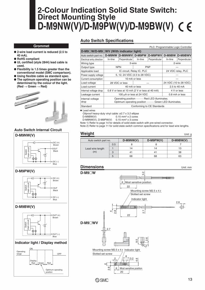
Weight Unit: g
Unit: mmDimensions
Auto switch part no.
0.5
1
3
5
D-M9NW(V)8
14
41
68
D-M9PW(V)8
14
41
68
D-M9BW(V)7
13
38
63
Lead wire length(m)
Grommet PLC: Programmable Logic Controller
Auto switch part no.
Electrical entry direction
Wiring type
Output type
Applicable load
Power supply voltage
Current consumption
Load voltage
Load current
Internal voltage drop
Leakage current
Internal voltage drop
Standard
D-M9NWVD-M9NW D-M9BW D-M9BWV
2-wire
—
24 VDC relay, PLC
—
—
24 VDC (10 to 28 VDC)
2.5 to 40 mA
4 V or less
0.8 mA or less
D-M9PWVD-M9PW
Operating position .......... Red LED illuminates.Optimum operating position .......... Green LED illuminates.
3-wire
IC circuit, Relay IC, PLC
5, 12, 24 VDC (4.5 to 28 VDC)
10 mA or less
40 mA or less
0.8 V or less at 10 mA (2 V or less at 40 mA)
100 μA or less at 24 VDC
Conforming to CE Standards
In-line Perpendicular In-line Perpendicular In-line Perpendicular
NPN PNP
28 VDC or less —
D-M9�W/D-M9�WV (With indicator light)
� Lead wires Oilproof heavy-duty vinyl cable: ø2.7 x 3.2 ellipse D-M9BW(V) 0.15 mm2 x 2 cores D-M9NW(V), D-M9PW(V) 0.15 mm2 x 3 coresNote 1) Refer to page 14 for details of solid state switch with pre-wired connector.Note 2) Refer to page 11 for solid state switch common specifications and for lead wire lengths.
� 2-wire load current is reduced (2.5 to 40 mA).
� RoHS compliant� UL certified (style 2844) lead cable is
used.� Flexibility is 1.5 times greater than the
conventional model (SMC comparison). � Using flexible cable as standard spec.� The optimum operating position can be
determined by the colour of the light. (Red → Green → Red)
D-M9NW(V)
D-M9BW(V)
D-M9PW(V)
Indicator light / Display method
Auto Switch Internal Circuit
ON
OFF
D-M9�W
D-M9�WV
Mounting screw M2.5 x 4 lSlotted set screw
Indicator light
2.7
22
2.6
4
2.8
4
2.6
9.5
Mounting screw M2.5 x 4 l Indicator light
Slotted set screw
2.8
4.6
4
620
28
3.2
Most sensitive position
2.7
2-Colour Indication Solid State Switch: Direct Mounting StyleD-M9NW(V)/D-M9PW(V)/D-M9BW(V)
OUTBlack
DC (+)Brown
DC (–)Blue
DC (+)Brown
OUTBlack
DC (–)Blue
OUT (+)Brown
OUT (–)Blue
Sw
itch
mai
n ci
rcui
tS
witc
hm
ain
circ
uit
Sw
itch
mai
n ci
rcui
t
Operatingrange
DisplayRed Green Red
Optimum operatingposition
22
3.2
6 Most sensitive position
14
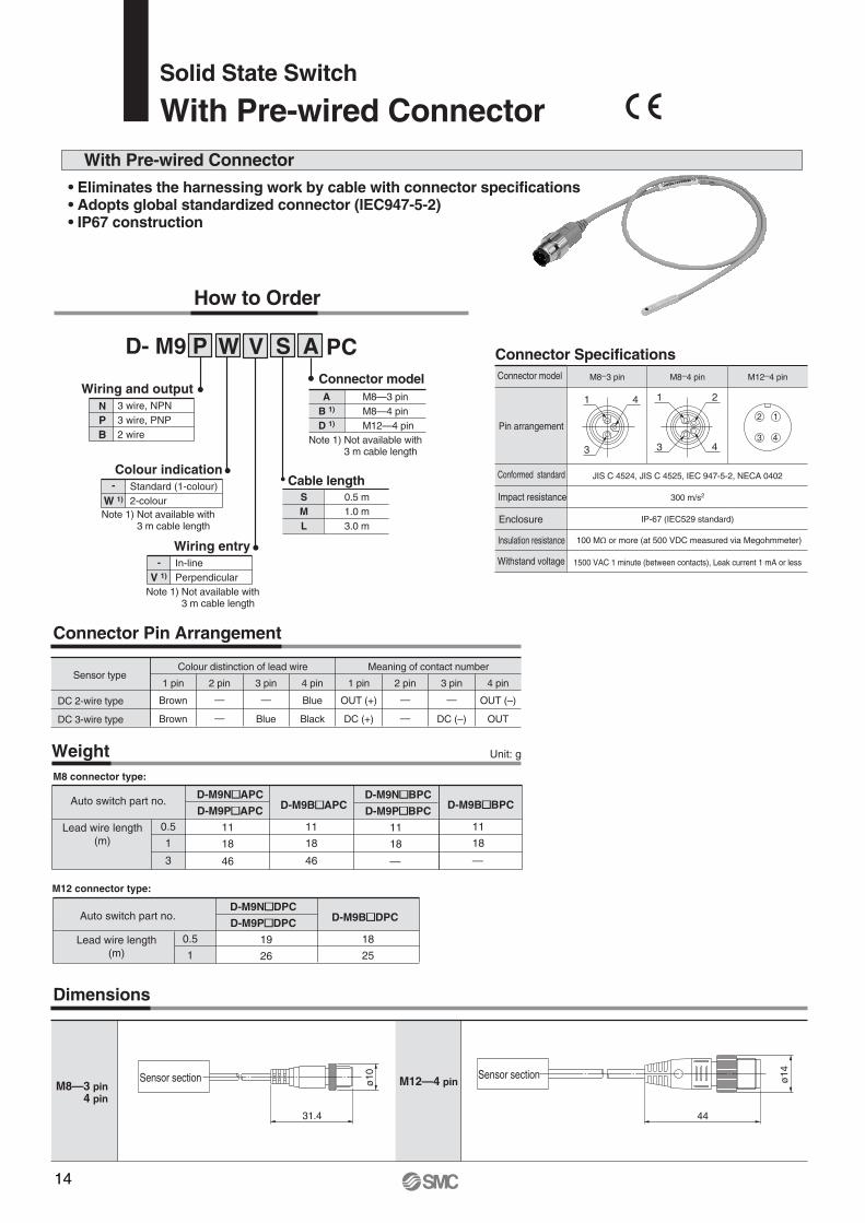
Solid State Switch
With Pre-wired Connector
• Eliminates the harnessing work by cable with connector specifications• Adopts global standardized connector (IEC947-5-2)• IP67 construction
How to Order
Cable length0.5 m1.0 m3.0 m
SML
Connector modelM8—3 pinM8—4 pinM12—4 pin
AB 1)
D 1)
Connector Specifications Connector model M8–3 pin M8–4 pin M12–4 pin
Pin arrangement
Conformed standard JIS C 4524, JIS C 4525, IEC 947-5-2, NECA 0402
Impact resistance 300 m/s2
Enclosure IP-67 (IEC529 standard)
Insulation resistance 100 MΩ or more (at 500 VDC measured via Megohmmeter)
Withstand voltage 1500 VAC 1 minute (between contacts), Leak current 1 mA or less
12
3 4
1 4
3
1 2
43
With Pre-wired Connector
Connector Pin Arrangement
Dimensions
Sensor type
DC 2-wire type
DC 3-wire type
Brown
Brown
1 pin
—
—
2 pin
—
Blue
3 pin
Blue
Black
4 pin
Colour distinction of lead wire Meaning of contact number
OUT (+)
DC (+)
1 pin
—
—
2 pin
—
DC (–)
3 pin 4 pin
M8—3 pin 4 pin
M12—4 pin ø14
44
Sensor section
ø10
31.4
Sensor section
OUT (–)
OUT
Weight Unit: g
0.5
1
3
D-M9N�APC
D-M9P�APC
11
18
46
D-M9B�APC
11
18
46
D-M9N�BPC
D-M9P�BPC
11
18
—
M8 connector type:
M12 connector type:
D-M9B�BPC
11
18
—
0.5
1
D-M9N�DPC
D-M9P�DPC
19
26
D-M9B�DPC
18
25
Auto switch part no.
Auto switch part no.
Lead wire length(m)
Lead wire length(m)
SD- M9 P W V
BP
3 wire, NPN
2 wire3 wire, PNP
N
Wiring and output
W 1)
Standard (1-colour)2-colour
-Colour indication
V 1)
In-linePerpendicular
-
Wiring entry
A PC
Note 1) Not available with 3 m cable length
Note 1) Not available with 3 m cable length
Note 1) Not available with 3 m cable length
15
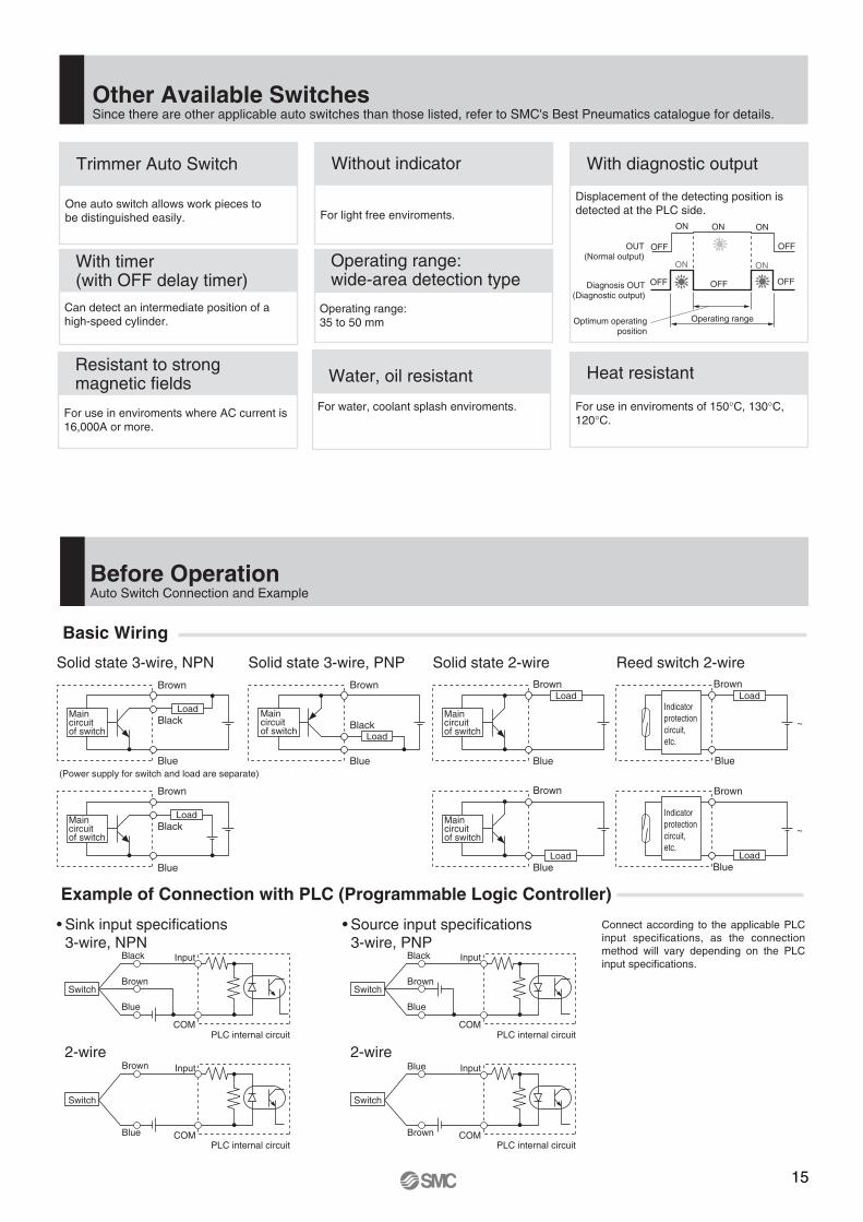
Other Available SwitchesSince there are other applicable auto switches than those listed, refer to SMC's Best Pneumatics catalogue for details.
Trimmer Auto Switch
One auto switch allows work pieces tobe distinguished easily.
Operating range
With diagnostic output
Displacement of the detecting position is detected at the PLC side.
Without indicator
For light free enviroments.
Diagnosis OUT(Diagnostic output)
OFF
OFF
ON ON ON
OFF
OFF
ON ON
OFF
OUT(Normal output)
Optimum operatingposition
With timer(with OFF delay timer)
Can detect an intermediate position of a high-speed cylinder.
Water, oil resistant
For water, coolant splash enviroments.
Operating range:wide-area detection type
Operating range:35 to 50 mm
Heat resistant
For use in enviroments of 150°C, 130°C, 120°C.
Resistant to strong magnetic fields
For use in enviroments where AC current is 16,000A or more.
Before OperationAuto Switch Connection and Example
Basic Wiring
Example of Connection with PLC (Programmable Logic Controller)
Solid state 3-wire, NPN Solid state 2-wireSolid state 3-wire, PNP
Main circuitof switch
Brown
Black
Blue
Brown
Black
Blue
Brown
Blue
Brown
Blue
Reed switch 2-wire
Indicatorprotectioncircuit,etc.
Brown
Blue
~
~
Brown
Blue
Indicatorprotectioncircuit,etc.
• Sink input specifications 3-wire, NPN
• Source input specifications 3-wire, PNP
2-wire
Switch
InputBlack
COM
Brown
Blue
2-wire
Switch
InputBlack
PLC internal circuitCOM
Brown
Blue
PLC internal circuit
PLC internal circuit
Switch
Input
Blue COM
Brown
PLC internal circuit
Switch
InputBlue
COMBrown
Brown
Black
Blue
Main circuitof switch
Main circuitof switch
Main circuitof switch
Main circuitof switch
Connect according to the applicable PLC input specifications, as the connection method will vary depending on the PLC input specifications.
(Power supply for switch and load are separate)
Load
Load
Load
Load
Load Load
Load
SMC CORPORATION Akihabara UDX 15F, 4-14-1, Sotokanda, Chiyoda-ku, Tokyo 101-0021, JAPAN Phone: 03-5207-8249 FAX: 03-5298-5362Specifications are subject to change without prior notice
and any obligation on the part of the manufacturer.
ARGENTINA, AUSTRALIA, BOLIVIA, BRASIL, CANADA, CHILE,CHINA, HONG KONG, INDIA, INDONESIA, MALAYSIA, MEXICO,NEW ZEALAND, PHILIPPINES, SINGAPORE, SOUTH KOREA,
TAIWAN, THAILAND, USA, VENEZUELA
OTHER SUBSIDIARIES WORLDWIDE:
© DiskArt™ 1988
© DiskArt™ UKSMC Pneumatics (UK) LtdVincent Avenue, Crownhill, Milton Keynes, MK8 0ANPhone: +44 (0)800 1382930 Fax: +44 (0)1908-555064E-mail: [email protected]://www.smcpneumatics.co.uk
AustriaSMC Pneumatik GmbH (Austria).Girakstrasse 8, A-2100 KorneuburgPhone: +43 2262-62280, Fax: +43 2262-62285E-mail: [email protected]://www.smc.at
Czech RepublicSMC Industrial Automation CZ s.r.o.Hudcova 78a, CZ-61200 BrnoPhone: +420 5 414 24611, Fax: +420 5 412 18034E-mail: [email protected]://www.smc.cz
PortugalSMC Sucursal Portugal, S.A.Rua de Engº Ferreira Dias 452, 4100-246 PortoPhone: +351 22-610-89-22, Fax: +351 22-610-89-36E-mail: [email protected]://www.smces.es
BelgiumSMC Pneumatics N.V./S.A.Nijverheidsstraat 20, B-2160 WommelgemPhone: +32 (0)3-355-1464, Fax: +32 (0)3-355-1466E-mail: [email protected]://www.smcpneumatics.be
LithuaniaSMC Pneumatics Lietuva, UABSavanoriu pr. 180, LT-01354 Vilnius, LithuaniaPhone: +370 5 264 81 26, Fax: +370 5 264 81 26
LatviaSMC Pneumatics Latvia SIASmerla 1-705, Riga LV-1006, LatviaPhone: +371 781-77-00, Fax: +371 781-77-01E-mail: [email protected]://www.smclv.lv
SwedenSMC Pneumatics Sweden ABEkhagsvägen 29-31, S-141 71 HuddingePhone: +46 (0)8-603 12 00, Fax: +46 (0)8-603 12 90E-mail: [email protected]://www.smc.nu
FranceSMC Pneumatique, S.A.1, Boulevard de Strasbourg, Parc Gustave EiffelBussy Saint Georges F-77607 Marne La Vallee Cedex 3Phone: +33 (0)1-6476 1000, Fax: +33 (0)1-6476 1010E-mail: [email protected]://www.smc-france.fr
FinlandSMC Pneumatics Finland OyPL72, Tiistinniityntie 4, SF-02031 ESPOOPhone: +358 207 513513, Fax: +358 207 513595E-mail: [email protected]://www.smc.fi
EstoniaSMC Pneumatics Estonia OÜLaki 12-101, 106 21 TallinnPhone: +372 (0)6 593540, Fax: +372 (0)6 593541E-mail: [email protected]://www.smcpneumatics.ee
GreeceSMC Hellas EPEAnagenniseos 7-9 - P.C. 14342. N. Philadelphia, AthensPhone: +30-210-2717265, Fax: +30-210-2717766E-mail: [email protected]://www.smchellas.gr
TurkeyEntek Pnömatik San. ve Tic Ltd. Sti.Perpa Tic. Merkezi Kat: 11 No: 1625, TR-80270 Okmeydani IstanbulPhone: +90 (0)212-221-1512, Fax: +90 (0)212-221-1519E-mail: [email protected]://www.entek.com.tr
PolandSMC Industrial Automation Polska Sp.z.o.o.ul. Konstruktorska 11A, PL-02-673 Warszawa, Phone: +48 22 548 5085, Fax: +48 22 548 5087E-mail: [email protected]://www.smc.pl
NetherlandsSMC Pneumatics BVDe Ruyterkade 120, NL-1011 AB AmsterdamPhone: +31 (0)20-5318888, Fax: +31 (0)20-5318880E-mail: [email protected]://www.smcpneumatics.nl
IrelandSMC Pneumatics (Ireland) Ltd.2002 Citywest Business Campus, Naas Road, Saggart, Co. DublinPhone: +353 (0)1-403 9000, Fax: +353 (0)1-464-0500E-mail: [email protected]://www.smcpneumatics.ie
HungarySMC Hungary Ipari Automatizálási Kft.Budafoki ut 107-113, H-1117 BudapestPhone: +36 1 371 1343, Fax: +36 1 371 1344E-mail: [email protected]://www.smc.hu
SwitzerlandSMC Pneumatik AGDorfstrasse 7, CH-8484 WeisslingenPhone: +41 (0)52-396-3131, Fax: +41 (0)52-396-3191E-mail: [email protected]://www.smc.ch
ItalySMC Italia S.p.AVia Garibaldi 62, I-20061Carugate, (Milano)Phone: +39 (0)2-92711, Fax: +39 (0)2-9271365E-mail: [email protected]://www.smcitalia.it
GermanySMC Pneumatik GmbHBoschring 13-15, D-63329 EgelsbachPhone: +49 (0)6103-4020, Fax: +49 (0)6103-402139E-mail: [email protected]://www.smc-pneumatik.de
SloveniaSMC industrijska Avtomatika d.o.o.Grajski trg 15, SLO-8360 ZuzemberkPhone: +386 738 85240 Fax: +386 738 85249E-mail: [email protected]://www.smc.si
SlovakiaSMC Priemyselná Automatizáciá, s.r.o.Námestie Martina Benku 10, SK-81107 BratislavaPhone: +421 2 444 56725, Fax: +421 2 444 56028E-mail: [email protected]://www.smc.sk
RomaniaSMC Romania srlStr Frunzei 29, Sector 2, BucharestPhone: +40 213205111, Fax: +40 213261489E-mail: [email protected]://www.smcromania.ro
NorwaySMC Pneumatics Norway A/SVollsveien 13 C, Granfos Næringspark N-1366 LysakerTel: +47 67 12 90 20, Fax: +47 67 12 90 21E-mail: [email protected]://www.smc-norge.no
DenmarkSMC Pneumatik A/SKnudsminde 4B, DK-8300 OdderPhone: +45 70252900, Fax: +45 70252901E-mail: [email protected]://www.smcdk.com
RussiaSMC Pneumatik LLC.4B Sverdlovskaja nab, St. Petersburg 195009Phone.:+812 718 5445, Fax:+812 718 5449E-mail: [email protected]://www.smc-pneumatik.ru
SpainSMC España, S.A.Zuazobidea 14, 01015 VitoriaPhone: +34 945-184 100, Fax: +34 945-184 124E-mail: [email protected]://www.smces.es
http://www.smceu.comhttp://www.smcworld.com
EUROPEAN SUBSIDIARIES:
BulgariaSMC Industrial Automation Bulgaria EOOD16 kliment Ohridski Blvd., fl.13 BG-1756 SofiaPhone:+359 2 9744492, Fax:+359 2 9744519E-mail: [email protected]://www.smc.bg
CroatiaSMC Industrijska automatika d.o.o.Crnomerec 12, 10000 ZAGREBPhone: +385 1 377 66 74, Fax: +385 1 377 66 74E-mail: [email protected]://www.smc.hr
1st printing LQ printing LQ 12 UK Printed in Spain


