Page 1
BANDKNIFE SHEARING OF WOOL FIBRES
A thesis
submitted in partial fulfilment of
the requirements for the Degree of
Doctor of Philosophy
in
Mechanical Engineering
in the
University of Canterbury
by
I{. F. HOSKING
B.E. (Hons)
UNIVERSITY OF CANTERBURY
1974
Page 2
TABLE OF CONTENTS
ACKNOWLEDGEMENTS
ABSTRACT
NOMENCLATURE
PAGE
(i)
(ii)
(iii)
CHAPTER I INTRODUCTION 1
1.1 Objectives of the Project 3
1.2 Requirements of a Skin Shearing Machine 4
1.3 A Review of Existing Raw Skin Shearing
Machines
1.4 Discussion
5
8
CHAPTER II INITIAL INVESTIGATION
CHAPTER III
II.l General Discussion 10
II.2 Design of the Experimental Model 10
II.3 Description of the Machine 11
II.4 Testing Procedure and Observations 13
II.5 Modifications to the Machine 14
II.6 Test Results 15
II.7 Discussion 17
WOOL
III.l
III. 2
III.3
III.4
III. 5
III. 6
III.7
SIDE LOCATION
General Discussion
Proposed System
The Investigation
Combs with Air Jets
Rotary Comb Wheel
Conclusions
Spike Penetration
18
18
20
25
27
27
28
Page 3
PAGE
CHAPTER IV THE EXPERIMENTAL SKIN SHEARING MACHINES I.
IV.l Discussion 30
IV.2 Description of the Machine
IV.3 Test Runs
IV.4 Modifications to the Machine
IV.5 Results of Modifications
IV.6 Discussion
CHAPTER V THE EXPERIMENTAL SKIN SHEARING MACHINES 2
31
35
37
39
42
V.l General Discussion 44
v. 2
v. 3
v. 4
v. 5
v. 6
v. 7
v. 8
The Cam Operated, Spike Retraction
Rolle;r
The Machine
Machine Trials
Modifications to the Machine
Results of Modifications
Discussion and Decisions
The Evans Roller
CHAPTER VI BLADE GUIDES
CHAPTER VII
VI.l General Discussion
VI.2 Design of the Blade Guide
VI.3 Tests of the Blade Guide
VI.4 Discussion of the Tests
VI.5 The Modified Blade Guide
VI.6 Tests of the Modified Blade Guide
VI.7 Effects of Tests on the Project
FLESH SIDE LOCATING SYSTEMS
44
46
48
50
50
51
51
59
60
65
67
67
69
69
VII.l Allowable Stubble Length Criteria 72
VII.2 Possible Flesh Side Locating Systems 73
Page 4
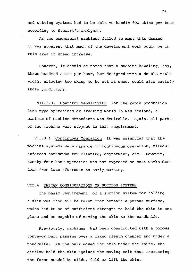
VII.3 Considerations of Suction Systems
VII.4 Design Considerations of Suction
Systems
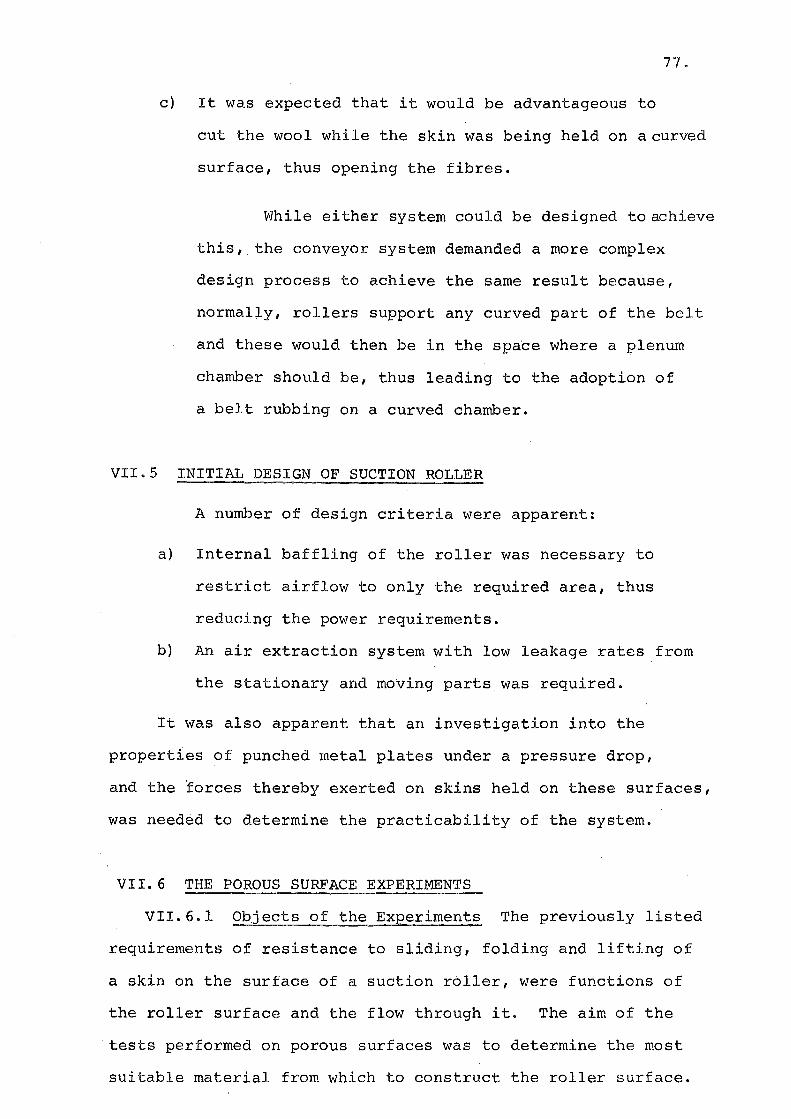
VII.5 Initial Design of Suction Roller
VII.6 The Porous Surface Experiments
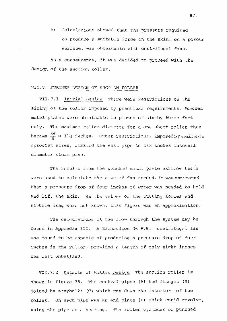
VII.7 Further Design of Suction Roller
VII.8 Performance of the Suction Roller
CHAPTER VIII THE EXPERIMENTAL BANDKNIFE
VIII.l Requirements for the Bandknife
VIII.2 Considerations of Commercial Bandknife
Equipment
PAGE
73
74
77
77
87
91
92
VIII.3 The Bandknife Design 96
VIII.4 Construction and Installation 105
VIII.5 Development of the Bandknife Machine 105
VIII.6 Summary of Bandknife Development
CHAPTER IX
and Performance
THE SUCTION HOLDING, SKIN SHEARING MACHINES
IX.l The Mark I Suction Roller and Band
knife Machine
IX.2 Performance of the Mark I Shearing
Machine
IX.3 The Mark II Suction Roller and Band-
knife Machine
IX.4 Performance of the Mark II Shearing
Machine
IX.5 Discussion of the Tests and Perform-
ance
113
114
115
120
122
136
Page 5
CHAPTER X SINGLE FIBRE CUTTING EXPERIMENTS
X.l Introduction
X.2 Summary of Fibre Properties
X.3 Initial Investigations
X.4 Design of Single Fibre Cutting
Machines
PAGE
139
139
141
142
X.S Description of the Mark I Microcutter 143
X.6 Obs~rvations, using the Mark I Micro-
cutter 145
X.7 Validity Check 146
X.8 The Mark II Microcutter 148
X. 9 Tests with the Mark II Microcutt.er 150
X.lO Results 155
CHAPTER XI WOOL REMOVAL THE FUTURE
APPENDICES: I
II
III
IV
v
VI
VII
VIII
REFERENCES
Model Wool Cutter, Graphs
Suction Experiment Graphs
Suction Roller Calculations
Bandknife Manufacturers
Bandknife Wheel Calculations
The Reise Raw Skin Shearing Machine
Alternative Handling Systems
Workshop Drawings
158
160
163
171
174
175
179
182
183
246
Page 6
INDEX TO ILLUSTRATIONS
(1) PLATES
Plate 1 Model Wool Cutting Machine
2 Spiked Belt Experimental Machine
3 Cam Operated Roller Machine
4 Evans Roller Expe.rimental Machine
5 Blade Guide
6 Toothed Blade Guide
7 Conveyor and Suction Roller during
Assembly
Following Page
14
33
50
57
67
71
91
8 Inclined Wheel Blade Grinder 106
9 Parallel Wheel Blade Grinder 110
10 Mark I Suction Roller Shearing Machine 114
11 Mark II Suction Roller Shearing Machine 136
12 Mark I Microcutter 144
13 Fibres During, and After, Cutting 145
14 Mark II Microcutter 149
15 Multiple Image Phbtography Sequences 152
16 High Speed Photography Sequences 156
(2) FIGURES
Figure 1
2
3
4
5
6
7
8
9
WPM Raw Skin Shearing Machine
Selbeck Raw Skin Shearing Machine
Model Wool Cutting Machine
Power, Torque vs. Speed Curves
Suggested Comb and Wire System
Comb Testing Conveyor
Plain Combs
Comb and Wheel Combinations
Air Jet Combs
6
9
12
16
i9
21
22
24
26
Page 7
Figure 10 Comb Wheel
11 Effect of Spikes
12 Bandknife Angles
13 Diagrammatic representation of the
Spiked Belt Shearing Machine
14 Bandknife Restraining Units
15 Diagrammatic representation of Mod-
ified Spiked Belt System
16 Bandknife Grinding Angles
17 Wool Guides
18 End View of Cam.Operated Roller
19 Diagrammatic representation of Cam
Operated Roller Shearing Machine
20 Operating Clearances for C.O.R.
21 Arrangement of Fixed Spike Roller
22 Diagrammatic representation of the
Working of the Evans Roller
23 Punched Steel Strip
24 Diagrammatic representation of the
Machine using Evans Roller
25 Deflecting Bandknife a positive
26 Defelcting Bandknife a negative
27 Profile of Bandknife guide
28 Bandknife Guide
29 Blade Thrust Bearing Arrangement
30 Deflecting Backing a positive
31 Deflecting Backing a negative
32 Comb Teeth Profiles
33 Proposed Suction System
34 Suction Experiment Apparatus
35 Punched Plate and Woven Mesh Clamp
Page
26
29
29
32
38
40
41
41
45
47
48
48
53
54
56
61
61
63
64
66
68
68
70
76
79
82
Page 8
Figure 36 Coefficient of Friction Graph
37 Force vs. Open Area Graph
38 Suction Roller
39 Suction Roller Support System
40 Mark I Suction Roller and Bandknife
Machine
Page
83
86
88
90
93
41 Clearance Diagram for Mark I machine 94
42 Bandknife Machine Frame 98
43 Cross Section of Bandknife Frame 99
44 Bandknife Support System 100
45 Parallel Wheel Grinding System 102
46 Inclined Wheel Grinding System 103
47 Forces on Inclined Grinding Wheel 108
48 Blade Support in Grinding Area 112
49 Skin Spreading Conveyor 116
50 Scraper and Take-off Roller on the
Mark I Machine 121
51 Mark II Suction Roller Shearing Machine 123
52 Skin Removal Roller 126
53 Details of Wool Handling System 127
54 Back-up bearing and Lubrication System 129
55 Machining of the Blade Guide 130
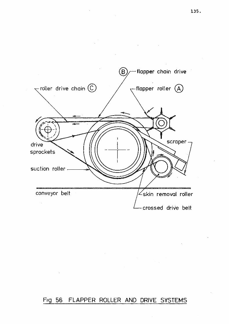
56 Flapper Roller and Drive Systems 135
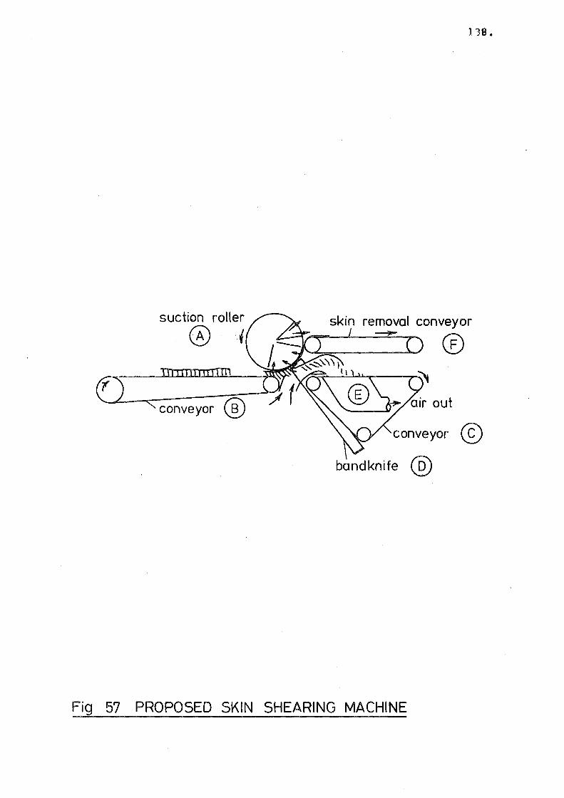
57 Proposed Skin Shearing Machine 138
58 Structure of the Wool Fibre 140
59 Mark I Microcutter 144
60 Appearance of Microcut Fibres 147
61 Mark II Single Febre Microcutter 149
62 Multiple Image Photography Apparatus 151
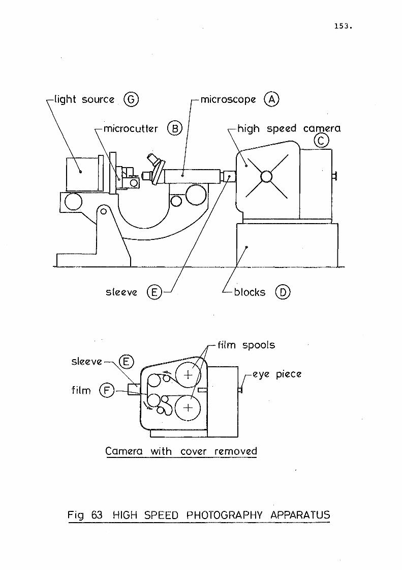
63 High Speed Photography Apparatus 153
Page 9
~
Figure 64 Calibration Curve 161
65 Calibration Curve 162
66 Force vs. Pressure No. 56 Plate 164
67 Force vs. Pressure No. 52 Plate 165
68 Force vs. Pressure No. 30 Plate 166
69 Force vs. Pressure No. 24 Plate 167
70 Power vs. Pressure No. 30, 56 Plates 168
71 Power vs. Pressure No. 52 Plate 169
72 Power vs. Pressure No. 24 Plate 170
73 Headless vs. Open Area ratio, plates 173
74 Bandknife Shaft S.F. and B.M. 178
75 Reise Skin Shearing Machine 180
Page 10
ACKNOWLEDGEMENTS
I am grateful to my supervisor Professor D.C. Stevenson
for his unfailing optimism and constant assistance during the
course of the project.
(i)
I would also like to thank Mr W.F. Newstead for his val
uable advice on the design problems of the project.
My thanks are also due to :
Mr R.G. Stewart, of the Wool Research Organisation of
New Zealand, whose enthusiasm for the project was a great
encouragement. The Mechanical Engineering Department Work-
shop staff and in particular Mr o. Bolt and Mr T.P. Wyatt
for their involvement in the practical aspects of this work.
Mrs B. Stout and Mrs D. Jeal who typed the script for this
thesis and Mrs J. Ritchie and Mrs V. Grey who prepared the
illustrations.
I wish to thank the Vernon Willey Trust Board and the
New Zealand Freezing Companies Association whose financial
assistance enabled the investigation to proceed to the
building of full scale machines.
I would like to thank the following individual freezing
companies for their assistance in supplying raw skins :
C.F.M. (Belfast), New Zealand Refrigerating Company (Islington),
and N.C.F. (Kaiapoi). Special thanks are due to the Alliance
Freezing Company in Invercargill, particularly to Mr D. Evans
for the use of a roller developed there.
Page 11
BAND KNIFE SHEARING OF WOOL FIBRES
ABSTRACT
The separation of the wool and the skin is an important
step in the processing of lamb and sheepskins in New Zealand
Freezing Works.
The chemical depilatory process used at present has a
number of disadvantages. It has been calculated that sub-
(ii)
stantial benefits to the freezing industry would accrue if
this process was replaced by a mechanical wool removal systemf
which left a short stubble of wool on the skin.
Initial investigations indicated the suitability of
a continuous bandknife machine for cutting the wool. This
thesis describes the investigation of both the cutting and
skin handling processes, the building of experimental machines,
and the testing and development proceeding from this.
Model and small scale machines were built to investigate
proposed systems, and two full size experimental machines were
constructed. These machines were developed to the stage
where reliable cutting was achieved. Although the length
of stubble remained uneconomically long, it was considered
that further development could overcome this.
The cutting process was investigated by means of
miniature, single fibre cutting machines. The technique of
using high speed photography to record the brief cutting event
while observing the fibre through a microscope was developed.
Page 12
(iii)
NOMENCLATURE
The names given to some objects and machines described
in this thesis could be ambiguous. A standard vocabulary
for objects having a number of names, or a common name, has
been used.
A WOOLLY SKIN is a sheepskin which has wool left on it. I
Skins to be processed by the shearing machine are in this
category.
The PELT is the skin of a sheep with the wool removed,
or with only a stubble left.
The FLEECE is the collective name for the wool fibres
after they have been removed from the pelt.
Confusion arises when bandknives are described because
the cutting blade itself and the entire machine can both be
referred to as the bandknife.
In this thesis the machine, as a whole, is referred to
as the BANDKNIFE MACHINE. The cutting blade is simply called
the BLADE.
Although bandknife blades do not use a shearing action
to cut (unlike hand-held shearing machines), it has become the
practice in the industry to refer to any wool cutting machine
as a SHEARING MACHINE. Likewise in this thesis removal of
the fleece, except for a short stubble, is referred to as
SHEARING and a pelt so processed is called a SHORN pelt.
A SHEAKLING PELT is a woolly skin which has been trimmed
to a wool length of around one to two inches.
Page 13
1.
CHAPTER I
BAND KNIFE SHEARING OF WOOL FIBRES
INTRODUCTION
Each year, over thirty five million sheep and lambs are
slaughtered in New Zealand. Wool reclaimed from the skins
of these animals accounts for about ten percent of the total
national wool clip. The skin, or pelt as it is known, is
used in shoe and garment leather.
The early stages of skin processing are usually
carried out in fellmongeries, which are generally in the
same buildings, or building complexes, that process the
carcasses, i.e. the ubiquitous New Zealand freezing works.
In recent years, dewooling has been carried out using
lime-sulphide depilation, in most freezing companies. The
main constituent of wool, keratin, is particularly susceptible
to attack by this chemical, while the collagen of the skin
is relatively resistant.
When a paint, consisting of a mixture of lime and sodium
sulphide, is applied to the flesh side of the skin, the
mixture slowly diffuses through the skin, dissolving part,
or all, of the wool roots. The wool can then be easily
removed, by pushing with the hands, or using a 'pulling'
machine. Most commonly, the wool is removed from the skins
manually. The skin is laid on a board, sloping away from
the worker, who pushes the wool off the skin with a blade,
or using his hands. The wool is usually classed for length,
fineness, etc. as it is removed.
Page 14
Although this system has found general acceptance,
being superior to any method previously devised, it does
have several disadvantages
(a) The wool is often left contaminated with lime,
or even damaged by the depilatory action;
(b) Because the pelts are left stacked for some
eighteen to twenty four hours to allow depilat
ion to occur, damage resulting from overheating
of the pelts in the stack is possible;
(c) Depilation is a batch process, with inherent
hc:mdl ing and storage problems;
(d) Wool removal, or pulling (as it is known), is
a physically demanding job. Older men often
find themselves unable to withstand the rigours
of the job, whereas the younger workers are
unlikely to be such competent wool classers.
2.
Predictions have been made of the economic advantages
of replacing sulphide depilation with a mechanical cutting
system, leaving a short stubble of around one quarter of an
inch. From work undertaken at the Wool Research Organisation
of New Zealand, Mr R.G. Stewart predicted that the freezing
industry would gain NZ$3.6mper annum if mechanical wool
removal could be achieved. 1
Although many New Zealand sheep are crossbred and have
a more coarse wool than such sheep as the Merino,which has
been bred as a wool producing animal, the wool is still in
demand. The presence of depilatory contamination is causing
concern in some markets, and this concern was another reason
for using mechanical wool removal.
Page 15
\;'
3.
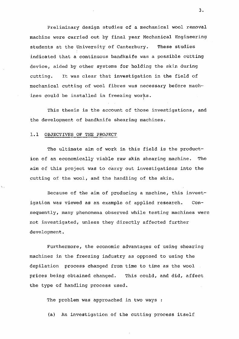
Preliminary design studies of a mechanical wool removal
machine were carried out by final year Mechanical Engineering
students at the University of Canterbury. These studies
indicated that a continuous bandknife was a possible cutting
device, aided by other systems for holding the skin during
cutting. It was clear that investigation in the field of
mechanical cutting of wool fibres was necessary before mach-
ines could be installed in freezing works. I
This thesis is the account of those investigations, and
the development of bandknife shearing machines.
1.1 OBJECTIVES OF THE PROJECT
The ultimate aim of work in this field is the product-
ion of an economically viable raw skin shearing machine. The
aim of this project was to c~rry out investigations into the
cutting of the wool, and the handling of the skin.
Because of the aim of producing a machine, this invest-
igation was viewed as an example of applied research. Con-
sequently, many phenomena observed while testing machines were
not investigated, unless they directly affected further
development.
Furthermore, the economic advantages of using shearing
machines in the freezing industry as opposed to using the
depilation process changed from time to time as the wool
prices being obtained changed. This could, and did, affect
the type of handling process used.
The problem was approached in two ways
(a) An investigation of the cutting process itself
Page 16
4.
was carried out, using both macroscopic and micro
scopic techniques;
(b) The cutting devices and handling systems were tested
in a series of experimental machines.
1.2 REQUIREMENTS OF A SKIN SHEARING MACHINE
The main requirement was that the wool be severed from
the skin, leaving as little stubble as possible and without
damaging the wool or the pelt.
The maximum amount of wool which could be left on the
skin varied , a;ccording to the fluctuating prices of wool,
but in general an average length of between one quarter and
three-eighths of an inch was acceptable.
The financial analyses of wool shearing had assumed
a throughput of 600 skins per hour. This figure was near the
average rate at which skin trimming and depilatory spraying
was done.
An important requirement was that the shorn fleece
remain a complete unit. Mixing of wool fibres from different
areas of the skin was not desirable, because classing was
then more difficult, and less rapid.
It was desirable that the machine require no special
skills to operate, as it was intended to introduce this machine
to a production line emp~oying unskilled labour. Because of
the adverse conditions under which freezing works machines
operate, the shearing machine was required to be rugged and
corrosion resistant. The need for continuous operation was a
further requirement. However, twenty-four hour operation was
not expected, as most New Zealand freezing works operate no
longer than twelve to fifteen hours a day.
Page 17
1.3 A REVIEW OF EXISTING ~~W SKIN SHEARING MACHINES
Initial investigations carried out by the Wool Research
Organisation of New Zealand, and coirespondence with users and
agents of existing machines,were expanded in 1971 by Mr R.Go
Stewart on his visit to the United States and Europe, and by
the author who visited the United States in 1974.
The following list of commercially built machines was
known in 1971. A further machine, built in the United States
was viewed in 1974. This is described in the Appendix,
because this thesis 1 as far as possible, has been laid out in
chronological order.
W.P.M. (Wlirtt Pelzmachinenfabrik) ~ The W.P.M. raw skin
shearing machine is used in a few New Zealand fellrnongeriesf
50
primarily for the trimming of shearling pelts. A diagrammatic
representation of this machine is shown in Figure 1.
The woolly skins are held on a woven wire mesh conveyor
belt, by the suction effect of an. evacuated plenum chamber
beneath the belt. A bandknife is used to cut the fibres, and
a centrifugal fan produces an airflow which bends the fibres
over the blade and transports them into a chute.
Although this machine performs the task of trimming to
a suitable length of around one inch with reliability, its
ability to cut to shorter lengths is very much dependent on
the operator's skill, and on the uniformity of the skin thick
ness.
The throughput is lower than required. Under favourable
conditions two hundred skins per hour could be processed.
This was considered inadequate.
Page 18
band knife
skin removal conveyor
chamber
F1g 1 WPM RAW SKIN SHEARING MACHINE
6.
Page 19
The severed wool is not kept as a fleece.
the machine is rugged and reliable.
However,
7.
As the manufacturer was not prepared to assist develop
ment in any way, it was decided that the W.P.M. machine was
not a suitable machine for development work.
Mercier-Freres: The French firm of Mercier-Freres produce
splitting machines for the tanning and plastics industries,
as well as other fellmongery machinery. At the time of
investigation, this firm was carrying out wool shearing ex
periments, and were reluctant to co-operate with this project.
Fecken-Kirfel: Fecken-Kirfel is a German firm producing
bandknife splitting machines for the plastics industry. Their
attempts at wool cutting had proved unsuccessful, and con
sequently they were reluctant to do any further experimenting.
McNeil-Femco: Femco bandknives are manufactured in Cuyahoga
Falls, Ohio, by the Falls Engineering Company, a division of
McNeil Corporation. The company supplies much of the United
States plastics industry with splitting machinery.
Wool cutting experiments had been carried out at Cuyahoga
Falls, with promising results. However, the number of sheep
slaughtered per year in the United States is not large, and
the development of raw skin shearing machines was not consider
ed economic.
During visits to the plant by Mr Stewart and the author,
a great deal of useful technical data was forthcoming. When
the full-scale raw skin shearing machine was constructed at
the University of Canterbury, the purchase of a McNeil-Femco
bandknife was considered. However, as detailed in Chapter
Page 20
8 .
VIII, Section 2, it was decided to construct a bandknife in the
Department workshops.
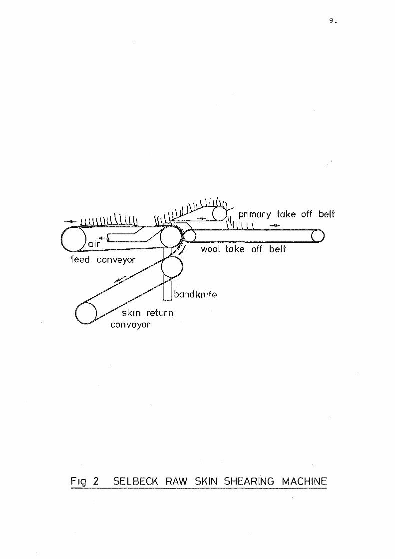
Selbeck: This German-made machine is similar in principle to
the W.P.M. in that a porous belt transports the skin, and air
is taken from an area below the bandknife, creating a band of
suction to hold the skin against the belt. The cut wool is
picked up by a conveyor, which has a small diameter end roller
mounted just above the blade. Unlike the W.P.M., the Selbeck
machine keeps the cut fleece intact. (See Figure 2).
The only Selbeck machine in New Zealand was being oper
ated by a firm producing shearling pelts and artificially
backed fleeces. The process of trimming the wool, and glue-
ing the cut fibres to a plastic sheet was developed by the
Wool Bureau of New York. As this was a classified project,
it was not possible to view the machine. However, it was
claimed that the machine could cut to stubble lengths of one
quarter of an inch, but at slow (150 per hour) rates.
1.4 DISCUSSION
None of the machines described were considered to be
satisfactory by the freezing companies in their present state.
Consequently, it was decided that a programme of experimentat
ion and eventually design of a full scale machine would be
carried out.
Page 21
return conveyor
wool take off belt
9 •
belt
Ftg 2 SELBECK RAW SKIN SHEARING MACHINE
Page 22
10.
CHAPTER II
INITIAL INVESTIGATIONS
II.l GENERAL DISCUSSION
Before design of a shearing machine could be attempted~
it was apparent that some knowledge of required speeds, powers
etc. was required.
After examining the performance of a number of commercial
machines (refer to Introduction), it was realised that, in
order that a machine might meet the specified throughput
requirements, it would be operating at speeds not approached
by any existing machines. Consequently it was decided that
a small test wool cutter would be built to determine some of
the necessary parameters. The use of a small scale machine
avoided the high costs and longer construction times of a
larger device.
II.2 DESIGN OF THE EXPERIMENTAL MODEL
As it was estimated, from observation of existing
machines, over five horsepower was needed to cut the wool from
a skin at the desired rate, a machine cutting only a thin
strip of woolly skin was needed.
The construction of a small scale bandknife did present
many problems, because it was difficult to construct a blade,
and equally difficult to obtain one. Consequently, it was
decided to cut with a sharpened disc, because the radius ratio
of a fibre to even a small disc is of the order of 10 3 •
It was not necessary for this machine to have a contin-
Page 23
11.
uous feed-in system. As the main object of the test was to
investigate the cutting phenomena, holding systems, which
were quite impractical for production machines, were satis
factory.for this device.
Provision was made for the measurement of power input
to the knife, and the speed of the knife.
II.3 DESCRIPTION OF THE MACHINE
The cutting device was a steel disc ((A) in Figure 3)
which was four inches in diameter, and one eighth of an inch
thick. The edge was sharpened in the form of a double bevel.
A vertical shaft (B), carried the disc. Tapered housing ball
bearings (C), supported the shaft and drive to the shaft was
by vee belt and pulley (D). The drive motor (F) was a one
tenth horsepower universal motor driving the shaft and disc
through a step up ratio vee-drive of three to one. A silicon
controlled rectifier speed control was used. Maximum unloaded
speed was 7000 r.p.m. at the motor shaft, giving a blade edge
speed of 360 feet per second.
A tacho-generator measured the drive motor shaft speed.
The motor was mounted in trunions (E) which enabled it
to rotate around its drive shaft axis. A Cantilever retrain
ing arm (G) was fitted with strain gauges, so that the surface
strain, and hence the motor torque, could be measured.
The one inch wide woolly skin samples were staped to a
rubber feed in belt (H), which passed under the cutting disc.
The length of residual stubble was varied by moving the motor
and blade unit supports up and down.
Page 24
cutting disc @
rubber feed in belt @
wheel
CD
shaft
pulley
bearings ©
tachogenerator output
12.
~------~=+~~~~ drive
skin sample motor
restraining arm@
trunions
® strain gauge reading
Fig 3 MODEL WOOL CUTTING MACHINE
Page 25
13.
Wooden wheels (J) of eight inch diameter, were the
conveyor end rollers. Although smaller wheels could have
been used, it was expected that other belts than the thin
rubber eventually used might be tested on this machine, and
would require a greater radius roller.
The feed conveyor was driven by another, one tenth
horsepower motor, through a worm gear reduction gearbox.
II.4 TESTING PROCEDURE, AND OBSERVATIONS
Before test runs with woolly skins were carried out,
the tachogenerator and strain gauges were calibrated. A
stroboscope was used to measure the motor speed over a range
of speeds, while the tachogenerator output was recorded.
The torque was calculated from the strain gauge reading
using bending theory. A no-load run was done to measure the
power consumed in friction, windage, etc.
Calibration curves for the tachogenerator and no load
input may be seen in Appendix 1.
In a typical test run, the blade was started and the
stapled-down skin fed under it. Despite a negative feedback-
control system on the motor, the disc speed invariably fell to
a steady speed below the original setting. In some cases,
at lower speeds, stalling of the disc occurred. The steady
state speed achieved with higher initial speeds was reached
before more than an inch of the skin had been cut, at normal
feed-in speeds.
It was immediately apparent that the power needed to
Page 26
14.
drive the disc had been underestimated, and consequently the
lower speed (and, unavoidably, reduced torque) readings were
not reliable. The disc often stalled. The feed-in mechanism
also had inadequate power to drive the skin samples under the
blade. Then drag of the stubble on the underside of the blade
was evidently greater than expected.
Other effects were noticed. The blade quickly lost its
edge, and then no longer cut the fibres. The wool fibres
tended to bend over away from the disc edge, and were then
dragged under the disc. This additional drag on the disc
increased the tendency for the motor to stall.
II.S MODIFICATIONS TO THE MACHINE
The mild steel disc originally used was replaced by
a slitting saw from a milling machine. The teeth were ground
off, and a double bevel edge was machined and sharpened. The
hardness of this blade was 1000 on the Vickers,Pyramidal
System, compared to the original blade of 450 VPN.
It was felt that a harder blade which kept its
edge longer would require less power to drive. In practice
this blade also lost its edge quickly, although not as rapidly
as the mild steel disc.
It was apparent that the stubble drag on the blade
absorbed a significant proportion of the power, and was not
typical of a bandknife drag because of the greater contact
area. This was partly due to the bending of the fibres during
cutting, with a consequent increase in stubble length.
Guards were fitted to the sides of the feed belt to
Page 27
15.
prevent sideways bending of the fibres. Because of the size
of the skin sample, edge effects were more apparent than
would be in a machine cutting right across an entire woolly
skin.
Increasing the power inputs to both the cutting disc
and the feed-in belt was difficult, especially the input to
the disc, because the drive motor was mounted on trunions.
In view of the amount of rebuilding needed, it was decided
not to increase the power, but to learn as much as possible
from the machine as it was.
II.6 TEST RESULTS
The curves of power and torque against disc edge speed
for a sharp edge, are shown in Figure 4. A minimum speed of
around fifty feet per second was necessary to ensure cutting
at the feed-in rate used. (This rate was reduced from the
designed speed (nine inches per second) to four inches per
second because of the insufficient power). In order to
achieve a throughput of 600 skins per hour, a feed-in speed
of nearly one foot per second is needed. (Approximately one
skin every four seconds).
With the reservation that the feed-in speed was lower
than desired, the power needed to cut at speeds above the
minimum cutting speed was calculated. The strain gauge read-
ings were converted to torque values using the system constants
and the power required to cut the wool from a strip of skin
was calculated. From this figure the power required to cut
across an entire skin was obtained.
Page 28
Ul U) (I)
w-:J § e-·Ul 0 c
1- (I)
E 0
,. 0
0·5
NO CUT
I
100
16.
4
2
Speed ( ft/sec) 200
Ftg 4 POWER/TORQUE vs SPEEDI 1" WIDE STRIP
Page 29
17.
A minimum edge speed for cutting at the desired feed-in
speed was not known, but estimated at 150 feet per second. It
seemed necessary then, to run any further machines at around
200 feet per second. It was estimated that four horsepower
would drive a bandknife at this speed, while cutting.
It was noted that wool is an unusually hard and abrasive
fibre to cut. This observation was confirmed by personnel in
the textile industry who had experienced rapid wear of knife
edges in fabric cutting machines. At this time investigations
into the basic mechanisms of fibre cutting were being carried
out, and this is described in Chapter X.
II.7 DISCUSSION
The tests on this machine left many questions on wool
cutting unanswered. However, it was considered that enough
basic information was to hand to build a small bandknife
machine. In summary, it was evident that
(a) a cutting speed of 200 feet per second was necessary;
(b) a method of frequently sharpening the blade was
essential;
(c) a power requirement for a full size machine was
estimated at four horsepower.
Consequently, it was decided to investigate ideas on holding
the woolly skin before and during cutting,and then to combine
the results of that work with the deductions from this
machine to build a skin-shearing machine. Further investig-
ation of bandknife cutting phenomena (wear rates, edge profile,
etc.) was dependent on having a machine capable of continuous
operation.
Page 30
18.
CHAPTER III
WOOL SIDE LOCATION
III.l GENERAL DISCUSSION
The pelt is seldom of uniform thickness. Even if all
the fatty matter is removed from the flesh side, there is
still a variation in thickness from one area to another. The
maximum thickness generally occurs around the neck and should
ers, and the minimum is found in the flank areas, particularly
under the legs.
Because of this, it is impossible to obtain a plane
surface on the wool side by locating the flesh side on the
plane. If a cutting device which can only operate in one
plane, such as a bandknife, is used, then it is desirable to
have the wool side surface also in one plane.
Two possible schemes were considered. One of these was
holding by introducing a number of horizontal wires into the
spaces between the wool,which would tend to flatten the skin,
particularly if a flexible support system were used to hold
the flesh side. The other idea was to push a network of
spikes into the wool,to press down on the skin. The develop
ment of this system is described in this Chapter, section 5.
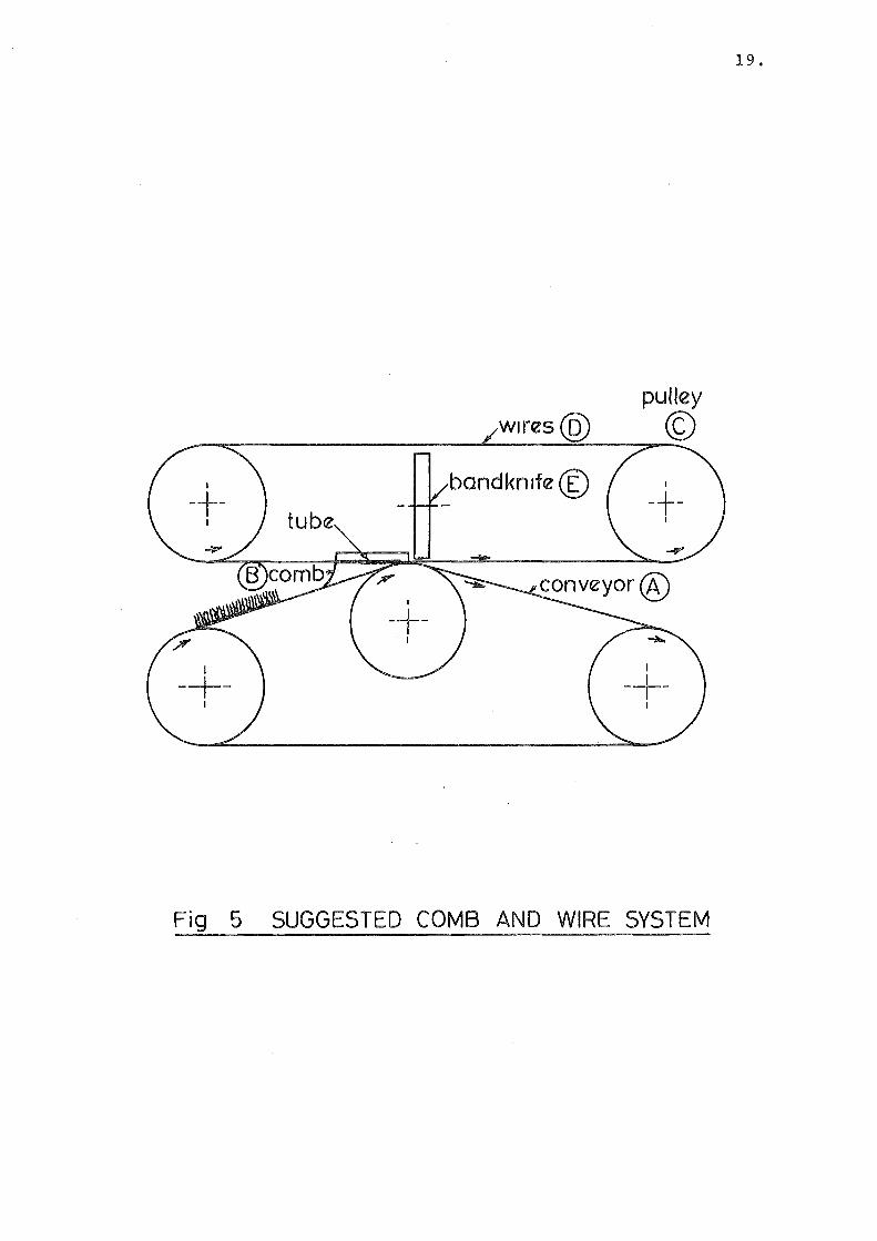
III.2 PROPOSED SYSTEM
A line diagram of a cutting system using wool side,
tensioned wire, location is shown in Figure 5. A conveyor
belt (A), carried the skins, flesh side down to a bank of combs
(B), which parted the wool. Running around pulleys (C), were
the tensioned wires (D). These ran through tunnels
Page 31
19.
pulley
© bandkn1fe©
Fig 5 SUGGESTED COMB AND WIRE SYSTEM
Page 32
20.
in the.combs, and were laid on the skin after the combs had
parted the wool. It was expected that these wires would run
at the same speed as the feed-in conveyor. While the skin was
being levelled and held, a bandknife (E) with its blade running
across the wires, then cut the fibres. Hence the wires locat
ed and held the skin against the conveyor (which could have a
flexible surface) and prevented the blade from damaging the
skin.
Obviously, the success of the system depended on the
ability of the combs to open up the fleece in straight lines,
without leaving any fibres under the wires.
Therefore, it was decided that investigations into comb
ing would be carried out before any machine, working on this
principle, was designed.
III.3 THE INVESTIGATION
III.3.1 Apparatus and Method.
A conveyor, shown in Figure 6 was built. This was built
using eighteen inch wide rollers (B) that were available at the
time, and an eighteen inch wide conveyor belt (A) ran over
these. The belt width was sufficient to take one half sheep
skin. The frame (C) had a number of support members for attach
ing comb banks (D). A one horsepower variable speed motor
(F) driving through a reduction gearbox (E) powered the conveyor.
The belt speed was variable up to one foot per second.
III.3.2 Plain Combs.
Figure 7 shows the profiles of a number of combs used.
These were made from sixteen gauge steel and were mounted in a
row, one inch apart.
A number of problems were apparent
Page 33
comb@
~tor If' gearbox\!::) V
angle frame © roller @
conveyor @ ~
ll
-
I
I I r-
I"""'
-I I _1-r r_
n -it
I
r;::;::lf "' I I
:o c=::n. I I ,....J
I
The system shown above IS set up for test1ng s1ngle comb and roller systems. Other combinations using the same frame were also used.
Fig. 6 COMB TESTING CONVEYOR
21.
Page 34
(1) Plane'-~-~-cx _________ _
drrectron of wool movement
~~ncave-~~r~-·-------a~l----------~
(3) Conv~'--x--~ ~---0...._! _____ _
(4) Double~, plane /L_1_cx
~~ '\~
(5)
b b
14
Concave r2
b b ~r---------~~
Convex 4
(6) Double Convex b
~~~--------~~b 4
Frg 7 PLAIN COMBS
22.
range of ex values be tween 20° and 80°
radrus & values between a and 3a
radrus & values between a and 3a
range of ~ from a./4 to 2 a
range of r 2 from r,/2 to r1
range of r2 from r1 /2 to r1
Page 35
23.
(a) Entry to the leading edge area proved difficult.
The skin tended to roll back, and jamming occurred.
(b) On those occasions when the leading edge did not
fold back, the combs jammed in the wool further
along the skin. When this occurred, the skin
slipped on the belt and moved no further.
(c) Wool fibres tend to grow in groups. The most
favourable parting line is consequently between
groups, but the machine had no way of sensing where
these areas were and, in any case, they are not
necessarily arranged in lines.
Wool on a raw skin is often matted. This obviously
increases the difficulties of parting.
From the tests it was apparent that a more positive
drive system was needed to overcome the forces required to
part the wool. A qualitative judgment indicated that the
sharp profile combs, such as (2) in Figure 7 performed better
than those with a less extreme taper, like (3) in Figure 7.
III. 3.,3COMBS WITH MECHANICAL ASSISTANCE
It was decided that combing could possibly be achieved
while the skin was being rolled between the centre conveyor
roller and a further driven roller above this. The upper
roller (1)
the slots.
in Figure 8, was slotted and the combs
The conveyor (3) remained unchanged.
(2) ran in
Referring to Figure 8, distance (b) is the clearance
between the roller and belt, and (a) is the distance between
the bottom of the comb and the underside of the roller. These
were varied throughout the tests, by adjusting the roller
Page 36
6''
®
©
3" a = 16 1" 1" 8 <b <2
1" 1" - <b <-8 2
r = 211
1" 1" 4 <b<2
1" a = 7.
F1g 8 COMB AND WHEEL COMBINATIONS
24.
Page 37
25.
position and making new combs.
The first tests were carried out with a value of 3/16"
for (a) and the roller surface speed identical to the belt
speed. Although the jamming problems no longer occurred,
parting was not done to a satisfactory depth. As (b) was
decreased, the parting improved, but the forces needed to move
the skin under the roller increased.
Other comb profiles with different values of (a) were
tried. These are also shown in Figure 8. Combs with pro-
files such as (B) in Figure 8 provided the best parting, but
jamming was still a problem.
When the combs projected below the roller, as in (C),
Figure 8, better parting,but higher forces,and a tendency to
' jam were observed.
A disturbing feature of the combing was that on some
matted skins, the forces required to drag the combs through
the wool were sufficiently large to cause tearing of the pelt.
It was concluded that plain combs, with or without rollers,
were not practical means of parting wool on raw sheepskins.
III.4 COMBS WITH AIR JETS
It was expected that an air jet could part wool in a
similar manner to a steel comb, and that if a jet was to be
used to part the wool ahead of a comb, the forces needed to
drive the skin under the comb could be reduced.
The comb shown in Figure 9 was constructed. The profile
was that of the previously most successful plain comb, and a
Page 38
26.
·> dJrect1on of wool movement
F1g 9 AIR JET COMB
d1rect1on of
F1g 10 COMB WHEEL
Page 39
27.
passage fed air from a union on the trailing edge to a nozzle
at the point. Air from a 100 p.s.i. line was discharged
through the jet.
Although the force needed to drive the woolly skin past
the comb was reduced, there was still a tendency for jamming
to occur, and for the leading edge to be caught.
Different comb profiles and jet angles were tried with
substantially the same result.
III.S ROTARY COMB WHEEL
In an attempt to introduce a comb to the wool at a
different speed to belt speed, a rotary comb wheel was built.
The wheel, Figure 10, was a ~~~ thick steel disc, one
foot in diameter. Around the diameter there were a number
of wedge shaped serations. These tapered to a point along
the leading edge. As the woolly skin passed under the wheel,
it was driven at various speeds relative to the feed speed,
from about three times faster in the same direction to three
times the speed in the opposite sense.
by a comb to maintain the parting made.
This was followed
This system also proved unsatisfactory, because of
inadequate penetration and jamming.
III.6 CONCLUSIONS
As none of the combing devices which had been tested
Droved capable of parting reliably, the concept of wire locat
ion, which depended on efficient combing for its success,
was abandoned.
Page 40
28.
III.7 SPIKE PENETRATION
A simple experiment conducted with a flat plate with
spikes protruding demonstrated that, if spikes with their
points in one plane are pushed into the wool side of a skin
resting on a resilient surface, there was a significant levell~
ing effect. There was little sign of crushing of the fibres.
{See Figure 11).
An important observation was that the levelling effect
was noticeable some distance from a row of spikes. Clearly
this effect was reduced as the distance increased, but it
was observed that, up to about one inch distance, the variat
ion in vertical position was of the order of one eighth of an
inch or less~ depending on the vertical force.
It was clear that a spike system could be used to level
the skin and prevent movement during cutting, provided the
spikes could be retracted before reaching the blade.
A system of continuously introducing spikes and retract
ing them was devised and as this was incorporated in a complete
cutting machine, it is described in the following chapter.
Page 41
29.
FK] 11 EFFECT OF SPIKES
CASE 2. a.
a. CONSIDERED ~~~~~~~~~"""'~;;::--- NEGATIVE
F1g 12 BANDKNIFE ANGLES
Page 42
30.
CHAPTER IV
THE EXPERIMENTAL SKIN SHEARING MACHINES. 1
IV.l DISCUSSION
It was decided to build an experimental machine using
the knowledge already gained from the disc cutting experiments
and the combing tests.
decision :-
There were three reasons for this
(a) A machine which worked reliably was needed to
investigate the wool cutting process.
(b) One of the objectives of the project was to
attempt to produce a working machine.
(c) The earlier work had shown that the best way
to investigate proposed handling systems, such
as the spike penetration system, was to try
them. Naturally, it was essential that the
ideas be given every change of working: that
is, adequate supporting systems, and a high
standard of construction, were necessary, because
in an investigation of this type, the maintenance
of small clearances etc. can be essential for
successful performance.
Furthermore, experience withthe disc cutter had indicated
the disadvantages of models. These invariably have some scale
effects.
However, as the machine was to be an experimental shear
ing rig, a test bed for ideas, it was not necessary that it
be built to prototype dimensions. For this reason, the
feed-in conveyor was the conveyor used in the combing exper
iments, with suitable modifications.
Page 43
IV.2 DESCRIPTION OF THE MACHINE
IV.2.1 General Description.
A diagrammatic representation of the machine is shown
in Figure 13.
Spike introduction and retraction from the skin was
31.
achieved by using a rubber conveyor belt with protruding spikes
(A), converging with a foam rubber covered feed-in conveyor
(B), from which it diverged as it passed around an end roller
(C), before reaching the bandknife blade (D).
At this stage no provision was made for the collection
of the cut wool, and these were expected to be carried out of
the cutting area by the continuation of the feed-in belt.
IV.2.2 Details of the Skin Handling System.
The spiked belt was made from a three-ply rubber con
veyor belt, and some 1500 two inch nails were driven throu'gh
it. A jig was used for spacing the spikes at three quarters
of an inch between adjacent rows and files. Following this
process the points of the nails were ground so that they were
in one plane. The ground ends were then heated with a weld-
ing torch to remove any grinding burrs.
The feed-in belt was the two-ply rubber belt used in
combing experiments, with a covering of one half inch thick
foam rubber. An idler roller (F) supported this belt at a
point directly below the drive roller of the spiked belt.
The woolly skin was laid on the lower belt, wool side
upwards. Spike penetration occurred as the two belts converg-
ed, and retraction occurred as the spiked belt moved up and
Page 44
end roller (C)
covered belt
idler roller (F)
Elevation . Note:- Dimension E ts distance from the band-knife edge to the start of spike divergence. - -
band knife (D) I
I
(B) (A) spiked belt foam covered
I · belt ' ' ~
-I I
Plan - -
-Fig 13 DIAGRAMATIC REPRESENTATION OF SPIKED
BELT SHEARING MACHINE.
32.
Page 45
33.
around its drive roller.
The bandknife blade was positioned as closely as possible
to the point of divergence of the spiked belt and the upper
skin surface, i.e. ~" to ~" above the lower belt and 1/8"
clear of the spike tips (see Figure 13).
A one horsepower variable speed motor, driving through
a fifteen to one reduction gearbox, powered both belts. An
adjustable diameter pulley, in the spiked belt drive line,
allowed synchronisation of the surface speeds of the two belts.
IV.2.3 Details of the Bandknife.
After consideration had been given to the three possible
methods of obtaining a bandknife :
(a) by buying a commercially built bandknife;
(b) by modifying a bandknife built for another
purpose;
(c) by building a bandknife;
it was decided to modify a used bandknife. Buying a new,
commercially built machine was expensive, and building a
complete machine was time consuming.
Modifications were carried out on an upright, fabric
cutting bandknife machine. This machine, a Kuris ZBM 58
had a blade sharpening system; and replacement blades, and
grinding wheels, were readily obtainable from a local agent.
A number of modifications were made to the machine.
The cutting table and stand were discarded, and support
structures to carry the bandknife in a horizontal position
were made. These structures (details of which may be found
in the modification drawings, Ap.VITI) incorporated an adjust-
Page 46
34.
ment whereby the bandknife could be rotated about an axis
through the working length of the blade, allowing the angle
between the blade and the horizontal plane to be varied up to
fifteen degrees in either direction. (See also Figure 12).
The frame of the bandknife, which was of cast iron, was
.cut midway between the wheels, and a fourteen inch long spac-
ing piece inserted. This spacer included a housing for the
grinding wheels which had been mounted on the working side of I
the machine previously. This modification increased the
working length of the bandknife, but necessitated the welding
in of extra blade length.
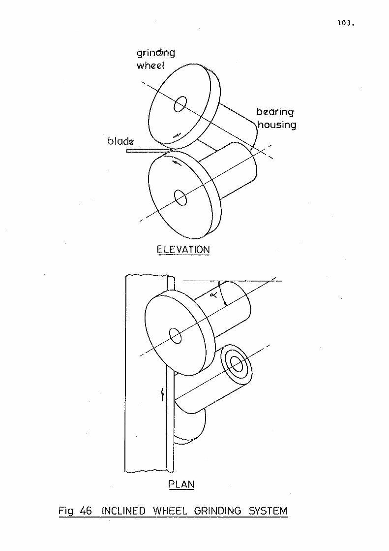
The blade sharpening system was not modified. This
consisted of two three inch diameter grinding wheels, which
were arranged to be turned by the blade while grinding it.
(Refer to Chapter VIIIand Figure 46).
As the original blade speed was ninety feet per second
(5400 feet per minute) , a new drive system was constructed
to increase the speed to 220 feet per second. A new drive
wheel shaft and bearing housing replaced the original system
of supporting the drive wheel on the motor shaft. A five
horsepower, 2850 r.p.m. motor replaced the one horsepower, 1410
r.p.m. unit. Drive to the wheel shaft was by vee belts,
permitting speed alteration by pulley size changes.
When the bandknife was installed in the machine, adjust-
ment of the clearance between the blade and the feed-in belt
was altered by moving the idler roller in the lower belt up
and down.
Page 47
35.
IV.3 TEST RUNS
IV.3.1 Experimental Conditions.
Initially the blade clearance was set at one half of an
inch, and the point of divergence of the paths of the spike
tips and the lower conveyor was then one inch distant from
the blade edge.
The food-in speed was set to one foot per second. The
blade was sharpened with equal angles above and below the
centreline. Initially, the blade was parallel to the lower
belt.
Woolly skins from crossbred sheep were used in the tests.
Quarter skin samples, with wool lengths varying from two to
four inches, were fed in to the machine.
sharpened between each run.
The blade was re-
During the tests the blade clearance and angle were
altered, and different feed-in speeds were tried.
A number of problems were evident. These could be
divided into problems with the bandknife, and problems with
the holding system.
IV.3.2 Performance of the Bandknife.
No problems were experienced with the unloaded running
of the bandknife, following the modifications. The blade
tracking and sharpening were both satisfactory, and the
higher speed did not ~ignificantly increase vibration in the
frame.
When the bandknife was working as part of the machine,
two factors were apparent :-
Page 48
(a) provided the blade was sharpened frequently,
the cutting of the wool fibres was readily
achieved, at the feed-in speeds required;
(b) on those skins which were shorn without damage
(refer to the next section), a gradual increase
in stubble length from the leading edge of the
skin to the rear was noticed. It was thought
that the blade was either twisting or bending
upwards, or both, under the loads imposed by
cutting.
36.
The angle between the blade and the lower belt was alter
ed to attempt to compensate for this. When the blade edge
was inclined downwards relative to the incoming belt the
opposite effect of reduced stubble length, and ultimately
pelt damage, occurred.
An upward inclination increased the stubble length
effect. As the phenomenon appeared to have no point of
neutral equilibrium, it was decided to modify the bandknife
by providing a system of restraining the blade. This is
described in section IV .4 - Modifications to the Machine.
IV.3.3 Performance of the Handling System.
The spiked belt holding system did not perform accept-
ably. Although the spikes provided a levelling and holding
action which allowed the blade to sever the wool fibres close
to the pelt, there was a tendency for the skin to be lifted
by the spikes as they diverged from the belt. This resulted
in damage to the skin, because the blade cut through the raised
pelt.
Page 49
37.
The tips of the spikes follow a longer path than those
at the belt end and as the spiked belt lifts from the lower
belt by passing around the drive roller, the spikes diverge.
This divergence effect was causing the spikes to grip any
matted areas, and thus lift the skin clear of the lower belt.
On short woolled, unmatted skins other effects were
noticed. The anticipated difficulty of introducing the lead-
ing edge to the blade without folding the skin back did not
eventuate. However, some wool was left uncut on that side of
the skin that the blade was moving toward. This was a narrow
band of fibres, evidently bent over, as they had no support
from adjacent fibres. The amount of wool left was not suff-
icient to cause concern at this stage, because other problems
were more evident.
It was decided to modify the handling system in an attempt
to overcome the lifting problem.
IV.4 MODIFICATIONS TO THE MACHINE
IV. 4 .1.. Modifications to the Bandknife.
One modification was made to the bandknife. This was
the installation of rollers above and below the blade at each
side of the working area. These were mounted on frames which
were clamped together to grip the blade (Figure 14}. This
modification reduced the free length of blade by thirty per-
cent, and was intended to reduce the tendency to twist or bend.
The resistance to bending of a uniformly loaded beam is prop
ortional to (free length} 4 and for twisting is proportional to
the free length.
IV.4.2 Modifications to the Skin Handling Systems
Two modifications were made in order to prevent the
Page 50
band knife
~
~
band knife frame
~ ~
~ ~
I
~ D T'
, bandknife
38.
rollers
bearing
ft housing
j l
I I ~ I
Fig 14 BANDKNIFE RESTRAINING UNITS
Page 51
39.
lifting of the skin by the spiked belt.
(a) The modified machine is shown in Figure 15.
The position of the upper belt relative to the
lower belt was altered. The idler roller in the I
lower belt was raised to a height of three inches
above the end rollers; the lower belt then traced
a triangular path. Both penetration and retract~
ion of the spikes was then achieved by convergence
and divergence ~f linear portions of the belts.
Spikes then did not diverge as before, during
retraction.
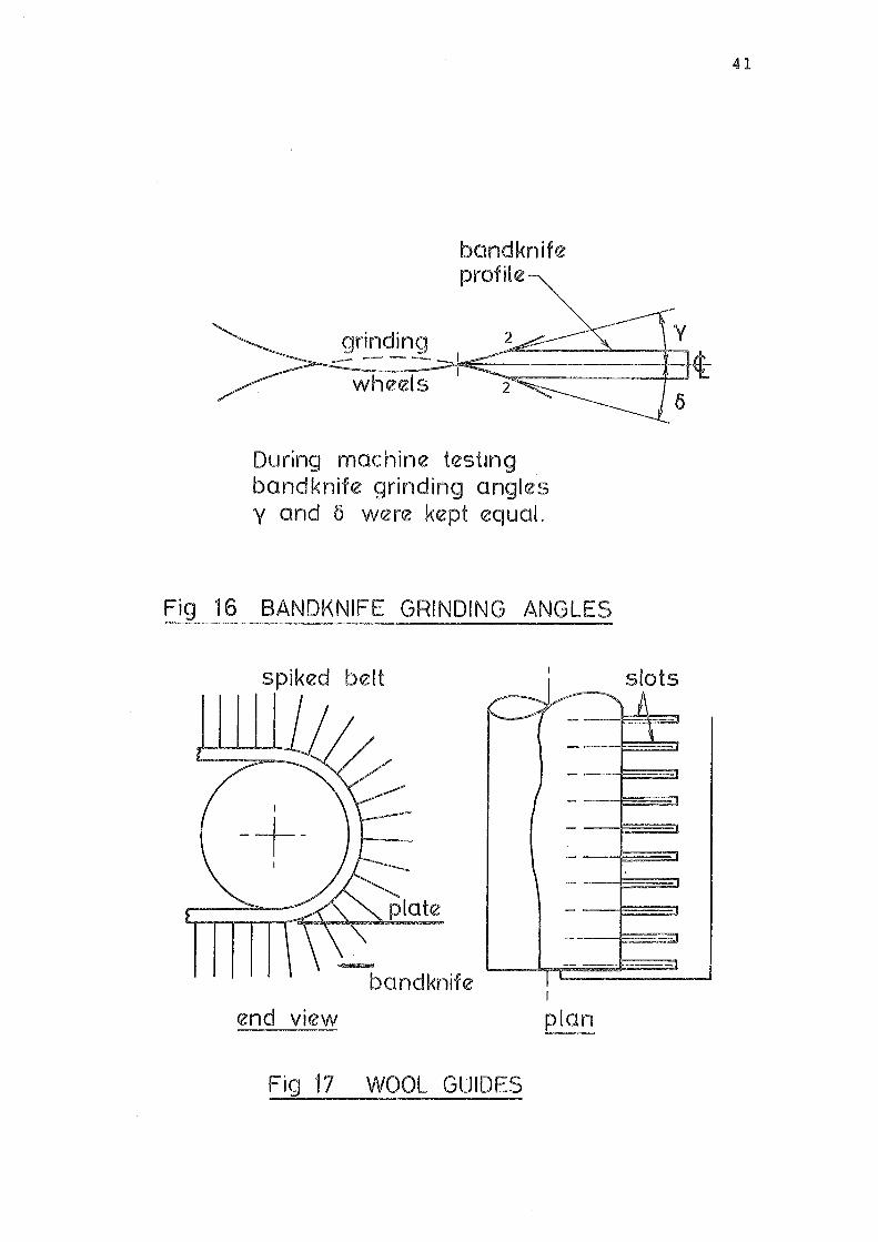
(b) A slotted plate (Figure 17) was mounted in front
of the drive roller of the spiked conveyor. The
spikes moved through the slots, and the parts of
the plate between the slots were intended to push
down any wool which was carried by the spiked belt.
IV.5 RESULTS OF MODIFICATIONS
IV.5.1 Results of Modifications to the Bandknife.
The problem of increase or decrease of stubble length,
noted in IV .• 3.2, was reduced, but not eliminated. As this
problem did not greatly affect the machine performance,
further modifications were not done immediately. However, a
slot type guide along the entire working length of the blade
was built later, and ChapterVIhas an account of blade guide
investigations.
IV.5.2 Results of Modifications to the Handling System.
The problem of skin lifting was still evident despite
the modified belts. Although the tendency for the skin to be
Page 52
(A) spiked
Elevation
Note increase in dimension (E) compared to that of figure 13
I
I I
I I I
Plan
40.
bandknife (D)
idler roller
I
I
I I I ' u I=
foam covered
belt
I
I
F1g 15 OIAGRAMATIC REPRESENTATION OF MODIFIED SPIKED BELT SHEARING MACHINE
Page 53
band knife profile~
grinding --------wheels
During machine test1ng bandknife grinding angles y and 5 were kept equal.
Fig 16 BANDKNIFE GRINDING ANGLES
spiked belt /-
~
I I
-+-1
band knife
end v1ew
Fig 17 WOOL GUIDES
--
----
--
--
I I
plan
41
slots _{J
\
I"""'" :J
Page 54
42.
lifted was decreased, it was not absent. Further, the less
rapid divergence pattern resulted in less holding and levelling
effect beuause the blade was, of necessity, further from the
point of divergence.
Again, combinations of clearances, and even a variation
in relative speed,were tried, but the system was still not
satisfactory.
The slotted plate rapidly accumulated a build-up of wool
fibres in the slots, and jammed.
IV.6 DISCUSSION
It was considered that there were two possible means of
improving the action of the spike penetration holding system:
(a) Either of the two systems already tested could
be used in conjunction with a system of holding
the skin against the lower belt, to resist the
upward forces; or
(b) another system of spike retraction, designed to
avoid lifting the skin could be devised.
Considering the former possibility, it was clear that
it was difficult to provide a means of holding the skin onto
the lower belt, while maintaining a resilient backing. The
use of suction, which was a possibility, was not compatible
with resilient backing because the compression effect would
result in the surrounding material being cut. If a rigid
backing was to be used, the ability of the spikes to push the
irregularities out would be greatly reduced.
Page 55
4 3.
It was also noted that the necessary distance between
the blade edge and the spikes was greater than desirable,
for optimum holding.
The second possibility, of devising a new spike system,
was adopted. It was decided that a positive retraction spike
system would be investigated. The development of this system
and the modified machines it was used in is described in the
next chapter.
Page 56
44.
CHAPTER V
THE EXPERIMENTAL SKIN SHEARING MACHINES 2
V.l GENERAL DISCUSSION
Experiments perfor~med with retraction of spikes from
small woolly skin samples suggested that the wool was less
likely to follow the spikes upward if:
a) The direction of motion of the spikes was at
right angles to the plane of the skin, and
b) The movement of the spikes was rapid.
These results suggested that a sudden, vertical
retraction of the spikes was desired.
Achieving such a motion with the spiked belt would
have been difficult. A new spike system was built.
V.2 THE CAM OPERATED SPIKE RETRACTION ROLLER
A roller which had rows of retracting spikes around
its circumference was built. Because the movement of the
spikes was controlled by cams, this roller became known as
the cam operated roller, a11d in ·the interests of brevity,
will be referred to in this thesis as the c.o.R.
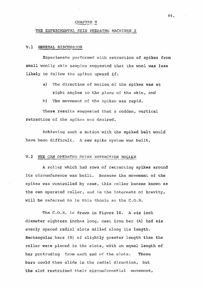
The C.O.R. is drawn in Figure 18. A six inch
diameter eighteen inches long, cast iron bar (A) had six
evenly spaced radial slots milled along its length.
Rectangular bars (B) of slightly greater length than the
roller were placed in the slots, with an equal length of
bar protruding from each end of the slots. These
bars could then slide in the radial direction, but
the slot restrained their circumferential movement,
Page 57
45.
direction of rotation
slotted roller
(A)
I I I I
\ \ \ \
spiral cam (D)
Note: Part (E) spike return springs hidden by cam (D) These stretch from (1) to (2) positions on every bar.
-
/ /
rectangular bars
(B)
spikes (C)
_....~path traced by spike tips
drive shaft (keyed to roller)
Fig 18 END VIEW OF CAM OPERATED ROLLER
Page 58
46.
and axial movement was prevented by locating pins.
Each ba~ had eighteen, two inch long spikes (C)
protruding from its outer edge. These spikes thus projectedfrom
the roller andv as they were attached to the bars, could only
move radially.
The ends of the bars rested on two spiral cams of
identical shape (D) • These cams had a gradual ramp over most
of the circumference, followed by an abrupt step to the minimum
diameter at a point following the point of maximum throw. See
Figure 20.
The bars were kept in contact with the cam by springs
(E) in Figure 18. The cams remained stationary and the roller
rotated, moving the bar projections over the cam profiles. The
roller rotated in a direction such that the bars moved around
the cam from minimum to maximum diameter. At the step, the
springs rapidly pulled the bars down on the lower part of the
cam.
The path then traced by the spikes was similar to the
cam profile but there was an inevitable small inertia lag at
the step.
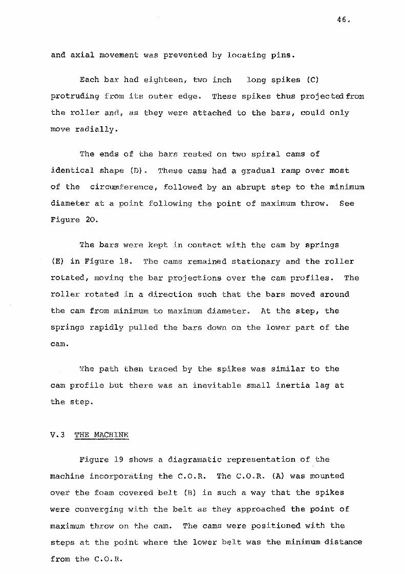
V.3 THE MACHINE
Figure 19 shows a diagramatic representation of the
machine incorporating the c.o.R. The C.O.R. (A) was mounted
over the foam covered belt (B) in such a way that the spikes
were converging with the belt as they approached the point of
maximum throw on the cam. The cams were positioned with the
steps at the point where the lower belt was the minimum distance
from the C.O.R.
Page 59
47.
bandknife (C)
cam operated roller (A)/ ~-_
~I I
foam covered belt (B)
(+J elevation
plan F1g 19 DIAGRAMATIC REPRESENTATION OF CAM
OPERATED ROLLER SHEARING MACHINE
Page 60
48.
The bandknife (C) was mounted with its blade above
the foam belt and a short distance past the point of spike
retraction.
The C.O.R. was driven from the same drive motor, gearbox
andvariablepulley that had powered the spiked belt system.
V.4 MACHINE TRIALS
The first runs were made to determine how close the blade
could be placed to the spikes. It was found that it was necessary
to pmsition the forward edge of the blade three-eighths of
an inch from the projection of the edge of the step, for the
feed in speed of one foot per second. See Figure 20.
Woolly skin cutting tests showed that reliable cutting
had not yet been achieved. The skin still tended to lift
and the bandknife still cut into the skin on occasion.
Observation of the cutting process suggested that the
combined effects of the cutting force and the stubble drag on
the blade caused the skin to buckle below rows of spikes. A I
disadvantage of the C.O.R. system was the increase in distance
between adjacent rows of spikes, compared to the spiked belt
system. From tip to tip, the average circumferential distance
from one row of spikes to the next was two and a quarter inches.
It was also noticed that the leading edge was not often
damaged. When buckling of the skin and the resulting cutting
of the pelt occurred it was often found near the trailing edge
of the skin.
The clearances between blade and belt, belt and roller
and roller and blade were all subjected to experimentation,
Page 61
(a) spike tip - belt tangent
(b)
(c)
clearance bandknife - belt tangent
clearance ~-
bandknife -spike path clearance I
-+-1
tangent to the belt below point (A)
geometric path of the spike tips
actual path of the spike tips
bandknife
49.
Fig 20.0PERATING CLEARANCES FOR C.O.R.
I I \ \
bandknife
I fixed spike roller
"
Fig 21 ARRANGEMENT OF FIXED SPIKE ROLLER
Page 62
so.
but these alterations did not change the overall pattern.
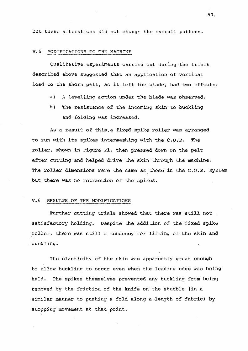
V.S MODIFICA'riONS TO THE MACHINE
Qualitative experiments carried out during the trials
described above suggested that an application of vertical
load to the shorn pelt, as it left the blade, had two effects:
a) A levelling action under the blade was observed.
b) The resistance of the incoming skin to buckling
and folding was increased.
As a result of this,a fixed spike roller was arranged
to run with its spikes intermeshing with the C.O.R. The
roller, shown in Figure 21, then pressed down on the pelt
after cutting and helped drive the skin through the machine.
The roller dimensions were the same as those in the C.O.R. system
but there was no retraction of the spikes.
V.6 RESULTS OF THE MODIFICATIONS
Further cutting trials showed that there was still not
satisfactory holding. Despite the addition of the fixed spike
roller, there was still a tendency for lifting of the skin and
buckling.
The elasticity of the skin was apparently great enough
to allow buckling to occur even when the leading edge was being
held. The spikes themselves prevented any buckling from being
removed by the friction of the knife on the stubble (in a
similar manner to pushing a fold along a length of fabric) by
stopping movement at that point.
Page 63
51.
V.7 DISCUSSION AND DECISIONS
It was clear that many of the problems arose from the
intermittent nature of the holding system. Although levelling
was still satisfactory, it was necessary to provide additional
uniform holding of the skin.
Two possibilities were:
a) A new retraction system with closely spaced spikes
b) Additional holding from the feed-in system, combined
with the existing C.O.R.
While there were feasible means of achieving the former \
possibility, it was thought that there was still the likelihood
of lifting of the skin. In any case, all the possible systems
would have been complex.
The latter suggestion had a number of advantages:
a) Additional holding from a resilient backing would
permit the continued use of the c.o.R. which had
been shown to contribute to the levelling of the
surface.
b) Additional holding down force would have theadvantage
of both preventing lifting and increasing the
resistance to sliding or folding of the skin.
During the time when a solution to the probl~m of holding
the skin againsta porous surface was being sought, an already
developed system became available. Consequently a modified
machine was constructed using this device.
V.8 THE EVANS ROLLER
V.8.1 Background A roller with a resilient backed,skin
holding surface had been developed by Mr D. Evans of the
Alliance Freezing Company, Invercargill, New Zealand. During
Page 64
52.
a visit to the plant the roller was demonstrated and offered
to the project.
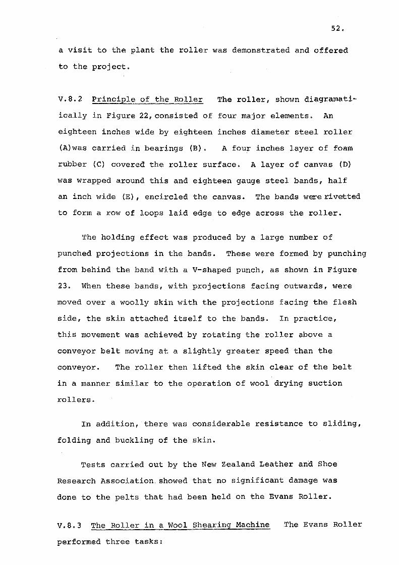
V.8.2 Principle of the Roller The roller, shown diagramati
ically in Figure 22, consisted of four major elements. An
eighteen inches wide by eighteen inches diameter steel roller
(A)was carried in bearings (B). A four inches layer of foam
rubber (C) covered the roller surface. A layer of canvas (D)
was wrapped around this and eighteen gauge steel bands, half
an inch wide (E), encircled the canvas. The bands were rlvetted
to form a row of loops laid edge to edge across the roller.
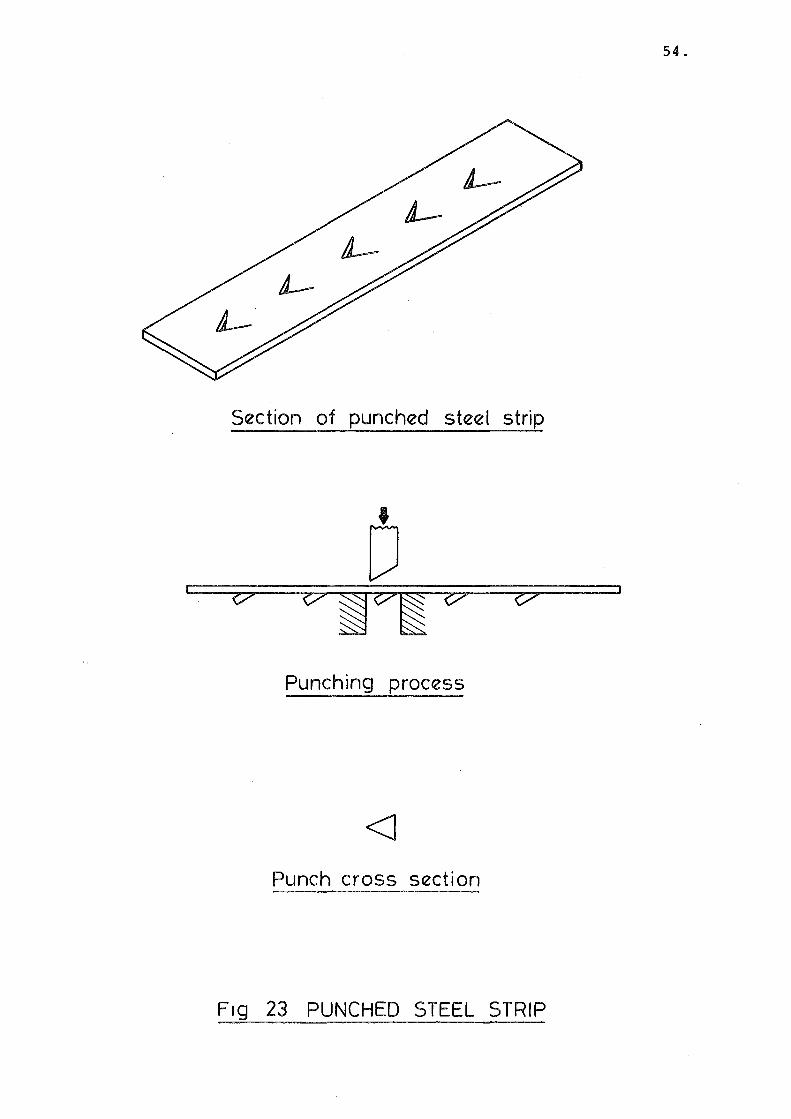
The holding effect was produced by a large number of
punched projections in the bands. These were formed by punching
from behind the band with a V-shaped punch, as shown in Figure
23. When these bands, with projections facing outwards, were
moved over a woolly skin with the projections facing the flesh
side, the skin attached itself to the bands. In practice,
this movement was achieved by rotating the roller above a
conveyor belt moving at a slightly greater speed than the
conveyor. The roller then lifted the skin clear of the belt
in a manner similar to the operation of wool drying suction
rollers.
In addition, there was considerable resistance to sliding,
folding and buckling of the skin.
Tests carried out by the New Zealand Leather and Shoe
Research Association. showed that no significant damage was
done to the pelts that had been held on the Evans Roller.
V.8.3 The Roller in a Wool Shearing Machine
performed three tasks:
The Evans Roller
Page 65
( 1 )
( 2)
53.
bearing @
-------foam © canvas layer @
steel bands ® conveyor
Fig 22 DIAGRAMMATIC REPRESENTATION OF THE
WORKING OF THE EVANS ROLLER
Page 66
54.
Section of punched steel strip
Punching process
<J Punch cross section
F1g 23 PUNCHED STEEL STRIP
Page 67
a} It took woolly skins which had been carried on
a conveyor wool side down, and presented them
55.
wool side up for cutting. As preliminary operations
such as trimming are preferably done with the flesh
side uppermost, this was an advantage for a holding
system.
b) It picked up the skins and held them in such a way
that there was resistance to both sliding and lifting.
As it was necessary to have the roller surface speed
slightly greater than the feed-in belt speed, there
was a stretching effect also.
c) As the roller had a flexible backing it could
accommodate variations in skin thickness.
The machine is represented in Figure 24. The original
feed belt of the previous machine (A) had no foam cover in
this machine. The Evans Roller (B) was mounted so as to run
in contact with this belt. Directly above the roller and 180°
away from the pick-up point, were placed the bandknife (C) and
C.O.R. (D).
A three horsepower motor, driving through a reduction
gearbox and variable pulley system, powered the roller.
Woolly skins were laid wool side down on the feed
conveyor,and the Evans roller, moving slightly faster than
the belt, gripped and picked up the skin. The skin was then
carried up to the cam-operated roller and bandknife. As
this was an experimental machine, no provision for pelt or
fleece handling was made.
V.8.4 Machine Trials Before cutting trials began, a series
of runs were made to determine the optimum speed differential
between the Evans Roller and the feed-in conveyor for efficient
Page 68
© @
56.
Evans roller
®
conveyor
®
(+) (+J
Fig 24 DIAGRAMATIC REPRESENTATION OF THE MACHINE USING EVANS ROLLER
Page 69
57.
lifting of the skin.
If the surface speed of the roller was less than, or
equal to the speed of the belt, the skin was not lifted.
However, if the roller moved at too great a speed, the skin
was overstretched and longitudinal wrinkles began to appear
in the pelt.
Eventually it was found that .a surface speed variation
of 1.05: 1 was a suitable operating condition.
With the bandknife and C.O.R. positions adjusted in the
same manner as described in IV.4, cutting tests were carried
out using crossbred skins.
Again it was found that reliable cutting was not achieved.
Despite the holding effect of the roller surface, buckling of
the skin between the rows of spikes still occurred and total
jamming of the system was common.
It was apparent that areas of the skin with fat adhering
were not being held by the roller and, if they were near the
leading edge, a folding problem was likely.
The effects of bandknife deflection were more apparent
on this machine than earlier models.
V.8.5 Discussion and Decisions It was not completely clear
which of two possible causes of unsatisfactory operation was
dominant.
a) The bandknife deflection may have been causing the
damage. It was conceivable that an unstable effect
like the increase/decrease of stubble length could
occur more than once on a skin. This was hinted
at by the occasional appearance of an undulating
Page 70
58.
length of stubble along 'the skin.
b) The handling system still had an intermittent rather
than continuous action.
It was decided to investigate the bandknife problems
by building guides for the blade. In practice, the blade
guide investigations were performed concurrently with other
modifications, but for the purposes of systematization, they
are described in the following chapter.
Page 71
59.
CHAPTER VI
BLADE GUIDES
VI.l GENERAL DISCUSSION
Many commercial bandknife machines, which are required
to make accurately positioned cuts, such as leather and plast-
ic splitting machines, have the working length of the blade I
running in a slot in a ri~id guide, with the sharpened edge
protruding. In some machines ·this guide is a heavy steel
or cast iron bar with a slot machined into it. In others,
particularly where the clearance under or above the blade is
critical, the blade moves between a pair of thin, but highly
tensioned bands.
When the bandknife machine was constructed, there were
three reasons advanced for not using a slotted blade guide
(a) Because of the higher than normal blade speed,
fears were held that overheating or seizure of
the blade in the guide might occur.
(b) The slot was expected to be a potential
' cause of wool or wool part.icle jamming.
(c) The presence of large amounts of metal below
the blade was undesirable because the shorn
skin was required to pass through the clearance
between the blade and the backing material.
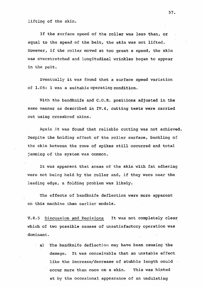
Because of the problems experienced with stubble length
variation, which was apparently caused by the deflection of
the blade, it was decided that a blade guide was necessary.
Moderate speed (64 frames per second) films of the machine
Page 72
60.
during cutting, and of the blade in particular, were replayed
at slower speeds. Viewing of the blade was difficult, because
the cut wool tended to cover the cutting area, but the films
did suggest that the blade was twisting during cutting.
A diagrammatic representation of the blade deflection,
and stubble length variation, is shown in Figures 25 and 26.
VI.2 DESIGN OF THE BLADE GUIDE
VI.2.1 General Considerations.
The requirements for the blade guide were divided into
four groups :-
VI.2.2 Material Choice.
It was considered necessary to use a spheroidal graphite
cast iron for the guide to prevent seizure at the operating
speeds. Cast iron is self-lubricating to a small extent, and
it was felt that the combination of the steel blade and cast
iron guide, together with moisture and lanolin from the wool,
would make any lubrication unnecessary. The use of lubricat
ing oil was not desirable because of the contamination problems
which might occur.
VI.2.3 Slot Clearances.
There were three reasons for having only small clearances
above and below the blade :-
(a) The blade could twist less if smaller clearances
were used. Apart from the obvious advantqge
of control of the blade, less deflection in the
slot lessened the possibilities of local over
heating, caused by, for example, the rear edge
of the blade rubbing on the slot surfaces.
(b) Blade vibration was a possibility. During run-up
Page 73
/wool fibres
conveyor increasing stubble length
Fig 25 DEFLECTING BANDKNIFE a. POSITIVE
/,wool fibres
conveyor decreasing stubble length
Fig 26 DEFLECTING BANDKNIFE a. NEGATIVE
61.
Page 74
62.
and run-down, the blade inevitably passed through
a series of vibratory modes. It was expected
that large clearances in the slot might intensify
the effect because of blade chatter.
(c) With a small clearance there was less chance of the
ingress of wool or pelt particles.
However, there were reasons for having larger clearances
(i) Frictional drag would be higher with small clear
ances, particularly if large amplitude vibrations
occurred;
(ii) If any foreign matter did enter the slot, seizure
would be more likely with small clearances than
with large.
It was decided to try a clearance of .004" total between
blade and guide. As the blade was of half inch depth, a slot
of depth one quarter inch was machined.
VI.2.4 Stiffness of the Guide.
It was important to have as little solid material under
the blade as possible. Most of the stiffness of,the guide
was required· to be contributed by the upper guide. A ramp
face for the wool and pelt to slide over was required on
both upper and lower guides.
The profile used is shown in Figure 27. The guide
was made in two halves, for ease of machining, and possibly,
later modification. The thin lower guide was screwed to the
large upper guide using countersunk screws.
Page 75
1" 1s
5" 1a
~::J;;It-----~---c:::~-4~~ ~ w·
B Note: Bandknife dimensions
1" A1 X B, = . 036'' X 2
Fig 27 PROFILE OF BANDKNIFE GUIDE
63.
Page 76
64.
slot for bandknife
Fig 28 BANDKNIFE GUIDE
Page 77
65.
VI.2.5 Control of Blade Position.
As the blade depth was reduced by sharpening, the length
of protruding blade was decreaied. Although this could be
compensated for by moving the blade guide rearward relative
to the edge, and relying on the crown effect of the bandknife
wheels to position the edge, it was expected that movement
might occur during cutting.
Consequently, thrust bearings were used to prevent rear-
ward movement of the blade. These were mounted at each end
of the blade guide, with the blade running just clear of the
tungsten faced, ball thrust bearings. (See Figure 29).
VI.3 TESTS OF THE BLADE GUIDE
The blade guide was tested by running for fifteen min-
utes under no load. After this time the blade and guide temp-
eratures had risen only some 2°C, and there was no sign of
seizure.
Woolly skin trials were carried out, and as far as
could be judged using the existing handling systems described
in the last chapter, no adverse effects were noticed. The
lower guide did not prevent the pelt from passing under the
blade, and the wool passed easily over the upper guide.
However, the test runs showed that the stubble length
still increased or decreased, as it did with an unguided
blade. Although the blade could no longer deflect far enough
to produce this effect, the backing material could. During
tests with the blade edge facing up relative to the skin, the
Page 78
66.
blade
tungsteh faced bearing
Fig 29 BLADE THRUST BEARING ARRANGEMENT
Page 79
67.
stubble length increased as the backing material compressed.
When the blade pointed downwards, it appeared that the skin
began to lift from the backing. The expected mechanisms
are sketched in Figures 30 and 31.
VI.4 DISCUSSION OF THE TESTS
The guide was shown to be successful, in that it produced
no noticeable adverse effects, and also guided the blade.
However, a basic weakness of resilient backing systems had
been revealed. It was now becoming clear that a more posit-
ive means of holding the skin was needed if the open slot
blade guide was to be used. However, there was the possib-
ility of shielding the skin from the edge, and using the
tendency for a downward inclined blade to cut into the skin
to form a feeding system.
Consequently, it was decided to design a modified blade
guide, incorporating a shielding system.
VI.S THE MODIFIED BLADE GUIDE
A new lower guide was made, and this is shown in Figure
32. This had small combs or teeth projecting forvTard a small
distance from the blade edge. This distance could be altered
by sliding the lower guide relative to the upper guide.
This clearly was not dissimilar to the combs tried earlier,
except that the physical size of the teeth, and the distance
the teeth were required to penetrate, were considerably smaller.
The expected distance from the teeth ends to the blade
edge was 1/8" to~", but provision was made to adjust from
3/8" to ~" behind the edge.
Page 80
68.
bandknife guide
~~~ increasing stubble
.--H~H4~~~~-~~~~ length
Fig 30 DEFLECTING BACKING a ZERO OR . POSITIVE
fibres band knife guide
Fig 31 DEFLECTING BACKING a NEGATIVE
Page 81
69.
The method of producing the teeth by a series of milled
slots is represented in Figure 32. The sharp edges left
by the machining were faired off with a hand file. Because
of the shape of the teeth, it was preferred that steel be used
rather than cast iron. The advantages of the cast iron guide,
namely its good frictional properties, were lost by doing this,
but the upper guide was still of cast iron.
VI.6 TESTS OF THE MODIFIED BLADE GUIDE
No load tests showed that,. despite the steel lower guide,
continuous operation did not result in seizure.
When woolly skins were fed into the machine, jamming
always occurred, unless the teeth did not project past the
blade edge.
When clean, dry and unmatted skins were used, the effect
persisted, thus eliminating a matting effect.
It was thought that, with a greater resisting force
than that supplied by the Evans roller, the problem might be
reduced, bu~ the chances of such a system producing a reliable
performance were considered low, because of the earlier
experiences with comb systems.
VI.7 EFFECTS OF THE TESTS ON THE PROJECT
The attempt to overcome the disadvantage of resilient I
backings, namely that of stubble length variation, by intro-
ducing a shielding system, and relying on operation on one
side of the neutral position, had not been successful.
Page 82
70.
Stage One
.A A
Stage Two
3" .
Section A-A
Fig 32 COMB TEETH PROFILES
Page 83
71.
The result was that resilient backings had been demon
strated to be unsuitable for bandknife cutting, at least with
in the types of systems experimented with in this project.
Consequently, spike penetration and wool. side location
were similarly shown to be impractical. Attention then moved
to flesh side location, and this is discussed in the next
chapters.
The performance of the machines using spike penetration
was not considered reliable enough to carry out blade profile
investi~tions or wear tests.
Further developments of blade guiding for long term
operation is discussed in Chapter IX.
Page 84
72.
FLESH SIDE LOCATING SYSTEMS
VII.l ALLOWABLE STUBBLE LENGTH CRITERIA
At the time when the project began a cost/benefit
analysis of Cutting of Wool from Sheepskins was carried out
by Stewart, R.G. 1 of the Wool Research Organisation of New
Zealand. The economics of wool shearing as opposed to
depilation had been based on a residual wool length of five
millimetres. Later investigations showed that, as a result
of changes in wool and pelt values, a greater length couldbe
tolerated. The effect of an increased residual stubble
allowance on the proposed holding systems was very important.
Skinsdo not have a uniform skin thickness. In particular, the
area around the neck is often thicker than the flank region
and the variation is of similar magnitude to the allowed
stubble length (often 3-4 mm).
Consequently, following both the recognition of the
allowable stubble increase and difficulties encountered with
the wool side location systems, flesh side locating processes
were considered.
The foregoing discussion refers to locating systems
using single plane cutting devices such as the continuous
bandknife. Alternatives, such as a row of hand shearing
pieces arranged so as to follow the skin contours, were seen
as possibilities but not as practical schemes for continuous
operation without a great deal of development. The relative
simplicity of a bandknife, as well as its suitability
for continuous operation and its proven value in shearling
cutting, indicated that a bandknife system should be
investigated.
Page 85
VII.2 POSSIBLE FLESH SIDE LOCATING SYSTEMS
Mechanical systems, such as the Evans Roller (refer
Chap.V) were considered to be impractical because:
a) The holding force had proved insufficient on
the Evans system, and
73.
b) No system which used a continuous gripping system
had been devised.
Suction systems, such as those used in the Selbeck
and W.P.M. machines, offered the advantages of:
a) Uniform force over the skin area, and
b) Relative simplicity of construction.
It was decided that, despite the less than satisfactory
performance of commercial bandknife machines using suction
systems to hold the skin, this type of locating system would
be developed.
VII.3 CONSIDERATIONS OF SUCTION SYSTEMS
The requirements for a successful holding system could
be divided into four groups, already broadly outlined in the
overall requirements for shearing machines (ref.Introduction).
VII.3.1 Sufficient Holding Force The skin was to be held
in such a way that during the cutting operation no sliding,
folding or lifting of the skin, relative to the backing
material coulq occur. This basic consideration was
satisfied by the commercial machines, at least when they were
run under their designed conditions of speed, length of cut
and operator skill.
VII.3.2 ~dequate Throughput In order to be economically
justifiable, the machine and, consequently, the feed, holding
Page 86
74.
and cutting systems had to be able to handle 600 skins per hour
according to Stewart's analysis.
As the commercial machines failed to meet this demand
it was apparent that much of the development work would be in
this area of speed increase.
However, it should be noted that a machine handling, say,
three hundred skins per hour, but designed with a double table
width, allowing two skins to be cut at once, could also satisfy
those conditions.
VII.3.3. Operator Sensitivity For the rapid production
line type operations of freezing works in New Zealand, a
minimum of machine attendants was desirable. Again, all parts
of the machine were subject to this requirement.
VII.3.4 Continuous Operation It was essential that the
machine systems were capable of continuous operation, without
enforced shutdowns for cleaning, adjustment, etc. However,
twenty-four hour operation was not expected as most worksclose
down from late afternoon to early morning.
VII.4 DESIGN CONSIDERATIONS OF SUCTION SYSTEMS
The basic requirement of a suction system for holding
a skin was that air be taken from beneath a porous surface, '
.which had to be of sufficient strength to hold the skin in one
plane and be capable of moving the skin to the bandknife.
Previously, machines had been constructed with a porous
conveyor belt passing over a fixed plenum chamber and under a
bandknife. As the belt moved the skin under the knife, the
airflow held the skin against the moving belt thus increasing
the force needed to slide, fold or lift the skin.
Page 87
75.
Two· possible porous materials were considered usable.
These were the wire mesh conveyor belt and the punched metal
plate. The wire mesh belt had been used in other machines and
the use of punched metal plate in wool drying drums was common.
It was decided to use a punched metal plate surface, .rolled
into a cylinder, (A) in Figure 33, and arranged to pick up the
skin from a feed-in conveyor (B) and carry the skin to a band
knife (C). This was of similar principle to the machine using
the Evans Roller.
The reasons for this choice were:
a) Uniform Surface: A punched metal cylinder has a
uniform and rigid surface, unlike a mesh belt which
has an irregular surface and needs some support to
maintain any of its path in a constant position.
Investigations of the local market and abroad,revealed
no porous conveyor material with a smooth surface.
b) Trimming: As it was expected that trimming of the
legs would still be a necessary step in the process,
consideration was given to the requirement that the
woolly skin be flesh side up for .trimming and spreading
(The reason for this is that the trimming knives
rapidly become blunt if they cut through the wool
rather than just the skin). It was difficult to
arrange a suction and conveyor system to work in this
manner because investigations into the spreading of
woolly skins had revealed that transfer of a skin
from one belt to another in a stretched out state was
impractical. However, a suction drum, lifting the
skin from the feed-in and trimming belt, could easily
fulfil this requirement.
Page 88
76.
device©
Fig 33 PROPOSED SUCTION SYSTEM
Page 89
77.
c) It was expected that it would be advantageous to
cut the wool while the skin was being held on acurved
surface, thus opening the fibres.
While either system could be designed toachieve
this,. the conveyor system demanded a more complex
design process to achieve the same result because,
normally, rollers support any curved part of the belt
and these would then be in the space where a plenum
chamber should be, thus leading to the adoption of
a belt rubbing on a curved chamber.
VII.5 INITIAL DESIGN OF SUCTION ROLLER
A number of design criteria were apparent:
a) Internal baffling of the roller was necessary to
restrict airflow to only the required area, thus
reducing the power requirements.
b) An air extraction system with low leakage rates from
the stationary and moving parts was required.
It was also apparent that .an investigation into the
properties of punched metal plates under a pressure drop,
and the ~orces thereby exerted on skins held on these surfaces,
was needed to determine the practicability of the system.
VII.6 THE POROUS SURFACE EXPERIMENTS
VII.6.1 Objects of the Experiments The previously listed
requirements of resistance to sliding, folding and lifting of
a skin on the surface of a suction roller, were functions of
the roller surface and the flow through it. The aim of the
tests performed on porous surfaces was to determine the most
suitable material from which to construct the roller surface.
Page 90
VII.6.2 Experimental Apparatus and Method A test rig
was constructed. This consisted of an open topped cubical
78.
plenum chamber ((A) in Figure 34) from which air was taken
via a duct (B) by means of a centrifugal fan (C). The open
top of the box could be covered with punched metal plate
samples (D) and skin samples (E) were placed on top of these.
The skin samples were small rectangles cut from woolly skins.
A clamp (F) on one edge was attached to a spring balance to
measure the force required to move 1the sample.
A manometer (G) recorded the pressure in!3J·de the chamber
and a pitot tube (H) was used for flow measurement in the duct.
Initially, a Richardson type O.B. centrifugal fan, driven
by a one horsepower motor via a varispeed unit, was used.
Later tests were carried out with a Richardson 3~ VB fan and
10 horsepower motor.
With the O.B. fan, the flow was varied 'by chang"rfig the ~ .. """
fan speed. A gate in the duct was used with the 3~ VB i~n.
With the smaller fan there was provision for relative
power measurement also.
During test runs the skin samples were washed before and
after sliding on any surface so that the flesh did not become
contaminated and possibly change its characteristics. With
the fan running and the sample in place, the pressure in the
chamber was noted and the limiting force required to slide the
sample measured.
Similarly, coefficient of friction tests, with weights
being placed on the skin when there was no airflow from the
chamber, were carried out.
Page 91
79,
/ \ clamp ® "";:"" skin ®
r- j samples ,...., ,. ~punched plate @
~
fan © pitot tube---@ -~---r--......-:::::!1.1..---.-1
duct
® plenum A chamber
p
VA
manometer @
--
fan motor
Fig 34 SUCTION EXPERIMENT APPARATUS
Page 92
80.
VII.6.3 Types of Porous Material Two classes of porous
material were investigated:
a) Punched steel plate: of 18 gauge thickness
b) Woven wire mesh: both brass and stainless steel.
It was expected that, although the roller was to be made
of punched steel plate, there could be a need for a covering
of wire mesh to! provide a more even distribution or to decrease
the open area.
Punched steel plates of the following sizes were used:
Plate No. Hole Size Holes/sq.inch Open Area Ratio (Number Drill)
1 24 23 .42
2 30 32 .40
3 52 88 .30
4 56 128 .19
Wire mesh of the following specifications was used
(B indicates a brass wire, S stainless steel)
Wires per· Wire Diam. Open Area Ratio Mesh No. Lin. Inch (ins.)
S20 20 .015 . 5
850 50 .009 .32 I S80 80 .005 .36
B30 30 .010 • 5
B60 60 .007 .32
B80 80 .005 .36
VII.6.4 Coefficient of Friction Tests In these experiments
only the action between the skin side of the woolly skin and
the plate or gauze, was important. All tests were done with
Page 93
81.
the sample spread skin side down.
Because of the flexibility of the skin it was difficult
to tell if all or just part of the sample was moving. Cons-
equently, the maximum steady force which could be applied
without the leading edge moving was taken as the limiting
condition. (In a machine, the skin could lift or slide in
one area but not in another, hence this criterion seemed I '
reasonable) . It was necessary to average a number of readings
to achieve a consistent result.
In order to ensure a flat surface, when wire mesh was
combined with the plates, the clamp shown in Figure 35 was
used. The wire mesh, laid on the plate, was held flat by
pushing on the wooden block (A). The clamp (B) which fitted
round,the block and sandwiched the protruding wire mesh, was
lowered into place and fastened down by tightening the thumb
screws (C) onto the extensions of the chamber legs (D) • The
wooden block was then removed leaving the wire mesh flat and
gripped at the edges.
It was expected that the pressure drop on the suction
roller would be under one foot of water (nearly one half pound
per square inch) so weighting was required to this pressure
only.
The results (see graph, Figure 36) show that:
a) In this range of pressures, the coefficient of
friction remained substantially constant for
clean, wet skin on the various materials.
b) There was very little difference in frictional
properties between the punched metal plates of
various sizes and the wire mesh samples. The
Page 94
mesh
punched plate
Fig 35 PUNCHED PLATE & WOVEN MESH CLAMP
82.
Page 95
..0
--
2
1
x PLATE 24, 52, 56
• PLATE 30
& ALL MESHES
0·2
83 •
Interface pressure (lb/ jn. sq) 0·4 . o.s
Fig 36 COEFFICIENT OF FRICTION TESTS
Page 96
84.
value of ~. the coefficient of friction for green
sheepskin on punched metal plates, came to approxi
mately .4, and the figure for gauzes was
indistinguishable within the experimental error.
VII. 6. 5 Sl~ing ~"e."::U:.§~~~.H:r~ Ai:t::flo~ During ·t.est runs with
the Richardson 0. B. fan o pressures reached in the plenum charr1ber
were less than those expected to be necessary in the suction
roller. Although the larger 3~ VB fan became available, it
had no provision for power measurement and the equipment to
measure this was not readily available.
Consequentlyv' the low pressure results were extrapola:ted
and the higher pressure result:s used to check some areas to
ensure the validity of that methocL
As vibration transmitted to thl~ plenum chamber from the
fan influenced the sliding force, particularly at low pressures,
weights were added to the skin samples t:o reduce this effect.
As the coefficient of friction was known to be linear at low
interface pressures, the additional resistance to sliding, due
to the pressure drop, was easily measured.
The results are tabulated and the graphs are included
in Appendix II.
In general, it was noted that, for a given pressure
drop, the force to slide the samplE:'! acres s a surface was lower
when a woven wire mesh was used. The exception was for No.52
plate.where a decrease in force was recorded when the plate was
uncovered. Clearly, the condition of the surface was important
and the meshes and plates were cleaned in carbon tetrachloride
between t.est.s.
Page 97
85.
A decrease in the arnount of power required to produce
a given pressure vJas no'c:ed vJhen wire meshes covered the plates.
In some cases there was a ratio of up to five between uncovered
plate and covered plate.
Howev~~r v rnesh cove:r~s were not. considered. practical for
two reasons~
a) Althoug·h t::he maximmn recorded value of the ratio
slicUnq foJ::·ce/poW(-H." ~"Has achieved with a mesh covered
plate (see Appendix IO 1 this ratio e.xceeded the
maximum ratio achieved by an uncovered plate by
only 45 percent, and
b) There were technical problems associated with the
fastening c'tYJ.d cleaning of mesh covers.· This wc:u.;;
demonstrated dur insr t:he e::.rt;:•<c~:d.ments, when difficulty
was experienced in main·taining -t:he mesh as a. level
surface.
The power required to produce the resistance to
sliding was not: considered at; important as the
achieving of a regular suction roller surface.
Consequently, the graph of sliding force vs. open area
for constant pressures was used to select a suitable plate
(Figure 37) and a graph of headless vc" k-1 0 open area, taken from
fluids text 4 used to cacu.late the flcM through the system a was
(refer Appendix III).
VII.6.5 Discussion of the Test Results From the results
a nu.mber of dm:dgn critc~ri<:t w~~re (~v.ident:
a) The optimum open area plate was likely to be in
the ranger~ .35+.45.
Page 98
. n
-1
Fi
0 ·1 Q.2
X
I I
X
/
I I
X
I
o.J
37 FORCE vs OPEN .Af~
: 6 •
X
\
Open area ratio ().L~ Q.5
PUNCHED PLATES
Page 99
87.
b) Calculations showed that the pressure required
to produce a suitable force on the skin, on a porous
surface, was obtainable with centrifugal fans.
As a consequence, it was decided to proceed with the
design of the suction roller.
VII. 7 FUHTHER DESIGN o:E' SUC'riON ROLLER
VII.7.1 Initial Des There were restrictions on the
sizing of the roller imposed by practical requirements. Pu:nched
metal plates were obtainable in plates of six by three feet
only. The maxim.um roll<~r diameter for a one sheet roller then
became ~rr6 """ 11~ inches. Other restrictions r imposed by availa.ble
sprocket sizes, limited the exit pipe to six inches internal
diameter steam pipe.
The results from the punched metal plate airflow tests
were used to calculate the size of fan needed. Itwasestimated
that a pressure drop of four inches of water was needed to hold
and lift the skin. As the values of the cutting forces and
stubble drag were not known f this fig-ure was an approximation.
The calculations of the flow through the system may be
found in Appendix III. A Richardson 3~ V.B. centrifugal fan
was found to be capable of producing a pressure drop of four
inches in the roller, provided a length of only eight inches
was left unbaffled.
VII.7.2 Details of Roller Des The suction roller is
shown in Figure 38. The central pipes (A) had flanges (B)
joined by staybolts (C) which ran down the interior of the
roller. On each pipe was an end plate (D) which could revolve,
using the pipe as a bearing. The rolled cylinder of punched
Page 100
88 .
• Staybolt 6" dia pipe
®
~End plate ( stationary) @
-~End p!ote (rotating} @
Air ~Drive sprocket ®
Fi .38 SUCTION ROLLER
Page 101
89.
steel plate (E) 'itli'.lS a.ttr:tcht:d at eaeh r:md t.o these (~ndplates.
A plate sprocket (F) was bolted to each endplate, and these
were driven by chains from a cross-shaft (G) . A one horsepower
variable speed motor and fifteen to one reduction gearbox
drove the sysb:'lm.
the roller. These covered the interior surface of the punched
cylinder, except for an eight inch deep band of open area.
The central pipes were the main structural support
members. The pipes W(~~ce held by clamps ((A) in Figure 39}
at each end of the roller. By loosening the clamps the
stationary parts of the system, i.e. the pipes, staybolts and
baffles, could be rotatecL rrh:Ls allowed adjustment of the
position of the suction area relative to any fixed object.
Alteration of the a.nc:la dimensions necessitated dismantling
of the roller.
The clamps holding the roller vJere welded to rotatable
platforms((B) in Figure 39) to provide a vertical adjustment
of roller position. One of these platforms also carried the
drive motor and :reduct.ion gearbox (C). The platforms were
supported by the brackets {D) , themselves part of a slide
system on the top of the main frame units (E) • Horizontal
adjustment of the roller position was thus possible.
A ducting system took the extracted air from the roller
to the fan.from one end of the roller. The other exit was
blanked off.
It was possible that skins might tend to stick to the
roller.and, consequently, the provision of a blowing system,
working on an area. of the :r·oller adjacent. to t.he suction band ,
was planned but not built at this stage.
Page 102
gearbox
clamps @
platform @ ·
brackets @
frame unrts ®
Frg 39 SUCTION ROLLER SUPPORT SYSTEM
90.
Page 103
91.
VII.8 PERFORMANCE OF THE SUCTION ROLLER
Pressure measurements along the length of the roller
open area showed a gradient of .02 inches w.g./inch from the
highest pressure of three inches w.g. to the lowest of two
inches. This was expected but, as the skin would be covering
the greater part of the open area during cutting, it was not
considered necessary to modify the baffling.
The average pressure in the roller was 25 percent lower
than calculated. It was considered that this was caused by
low assumptions of the entry coefficients to the pipe system.
However, the working ability of the roller was the crucial
factor. Tests showed that, although the roller would hold a
skin in place, once it was pressed over the suction area, heavy
skins could not be lifted from the feed-in belt.
There was little alternative but to use a larger fan to
produce a greater flow and greater pressure drop. Calculations
were based on a requirement of a 10" w.g. pressure differential
in this case. From the calculations (Appendix III) it was
clear a larger fan, of the Series 4 range of Richardson fans,
was required. When this fan was used an average pressure of
9.5" w.g. was recorded, and holding and skin pick-up were
satisfactory. However, ~ntil the roller could be included in
a cutting machine, its effectiveness could not be accurately
judged.
It was expected that the use of such a larg~ fan
(50 horsepower input) could be avoided by suitable ducting
design. However, at this stage of the project, it .. was decided
that the approach to the problem was one of making the system
work rather than investigating air flow phenomena.
Page 104
92.
CHAPTER VIII
THE EXPERIMENTAL BANDKNIFE MACHINE
VIII.l REQUIREMENTS FOR THE BANDKNIFE MACHINE
The required design features of the bandknife machine
could be grouped into two classes. :
(a) The physical size and shape limitations imposed
on the design by the presence of existing
structures.
(b) The operational requirements of speed of blade,
sharpening, and adjustments of blade positions.
It was necessary that the blade working length be
sufficient to enable the largest skins to be processed.
This meant that a working length of four feet was necessary.
The general plan of the MK I suction holding, raw skin
shearing machine (shown in Figure 40, and described in Chapter
IX) also influenced the frame design. The bandknife (A)
in the figure was expected to be run in the inverted positio.n
shown. However, a range of possible positions of the blade,
relative to the suction roller were required. Adjustment
of the clearance between the blade and the suction roller
(dimension (D) in Figure 41), and the angle between the
blade and the tangentto the roller ((E) in Figure 41) were also
required.
It was believed,· as a result of the experiments carried
out (see Chapter I), and from experience with the Kuris band
knife systems (Chapters, IV, V, VI) that a blade speed of 200
to 250 feet per second (12,000 to 15,000 feet per minute) was
required.
Page 105
suction roller
conveyor @ t t
plenum chamber
®
93.
1 bandknife @
air out
Fig 40 MARK I SUCTION ROLLER AND BANDKNIFE
MACHINE
Page 106
94.
I
--+---1
(B)
Fig 41 CLEARANCE DIAGRAM FOR MARK I MACHINE
Page 107
These same investigations had shown that wool is an
abrasive material to cut, and that frequent or continuous
sharpening of the blade edge would be necessary.
VIII.2 CONSIDERATIONS OF COMMERCIAL BANDKNIFE EQUIPMENT
95.
Before designing and constructing a bandknife machine
to fulfil the above-mentioned requirements, a survey of
commercial machines was carried out to determine their suit
ability for the task.
Many commercial machines are built for splitting solid
materials like leather or plastic foam, and similar machines,
with tooth-edged blades, are used for cutting metals, timber,
etc.
In general, commercial bandknife machines are designed
to run at speeds less than 85 feet per second (5,100 feet
per minute) and are not designed to overspeed to 15,000 feet
per minute in safety. All of the machines considered would
have needed extensive modification to their basic structure,
as well as strengthening for the dynamic loadings imposed,
in order that the required adjustments of clearance, angle of
attack and angular position would be possible.
The cost of buying a machine would have been about
NZ$15,000 - $20,000. A coiting for a locally built bandknife
showed a $1,000 material costf and $3,000 labour costs were
to be expected.
On the basis of these considerations, it was decided
to design and build a bandknife machine at the University of
Canterbury.
Page 108
96.
The manufacturers, whose products were included in the
survey, are listed in Appendix IV.
It should be noted that the decision to build a band
knife machine was taken during the initial design stages of
the suction roller, and that the roller and the bandknife were
designed together.
VIII.3 THE BANDKNIFE DESIGN
VIII.3.1 The Blade and Wheels.
A blade from a Rizzi splitting machine was used because
knife technology is so far advanced that the construction of
a blade was clearly impractical. This blade was 244" long,
with a width of 2~" and a thickness of .056" (17 swg).
Design calculations (see Appendix V) showed that a wheel
diameter of 26" was required if the band was to have an inf-
inite fatigue life. (The original machine had 26" wheels,
but further calculation showed that these, which were soft iron
castings, were not safe at the speeds of the order of 2250
r.p.m., that were necessary to achieve a 250 feet per second
blade speed.
Therefore, after calculations (Appendix V) showed that
steel wheels were safe at these speeds, new wheels, fabricated
from mild steel sections,were constructed. These wheels
had a three inch wide flange, which was tapered towards the
back-up ridge at the rear of the drive wheel, and was crowned
on the take-up wheel.
The wheels were flange mounted onto cantilevered shafts,
to facilitate blade removal.
Page 109
97.
VIII.3.2 The Main Frame.
The requirement that the wheels be cantilever mounted
meant that the main structure of the bandknife frame was pos
itioned behind the wheels. The stiffness of the structure
was extremely important, because any deflection could cause
the blade to leave its tracking position.
Welded steel fabrication was chosen as the construction
method because :
(a) it was a rapid system; and
(b) this was a less expensive method than casting
or forging large sections of the frame.
In order to facilitate rapid construction, many stock
sections were used in the fabrication.
The frame is shown in Figure 42. It was decided
to keep the area between the wheels (A) free, so a backbone
type main frame was used. The main beam (B) (also sketched
in cross section - Figure 43) incorporated a box to house
the grinding wheels (C) , and terminated at each end in diagonal
beams, passing through the centre lines of each wheel, and
carrying the bearing mounting (D) at the drive end and the
adjustment slide (E) at the take-up end.
Bars (F) were bolted over the front of the wheels, to
carry the tilt adjuster supports.
VIII.3.3 The Support System.
The central pipe of the suction roller was used to carry
the bandknife machine. The support system is shown in Figure
44. Clamps (A) at each end of the machine gripped the pipe (B).
The clamps carried the arm (C) which was mounted in bearings
Page 110
grinding enclosure © main beam @
support brgckeJs @ adjustment slide @
·bearing housing 1
@
tilt adjuster support . bars ®
Fig 42 BANDKNIFE MACHINE FRAME
98.
.......
" \ \
I /
I I
Page 111
I llr-II II
II II y y /
/
//
3" x 1r RHS
blade
2" x 2" RHS
'-r Flat
Fig 43 CROSS SECTION OF BANDKNIFE FRAME
99.
Page 112
angle adjuster
adjuster arm ©
counterweight
bandknife
0
~---......o::s;::::>_-:=----~:-----0~ clearance adjuster
suction roller ®
clamp®
pipe @
Fig 44 BANDKNIFE SUPPORT SYSTEM
100.
Page 113
101.
at the elbow, and the horizontal section controlled the knife
clearance (D) and the vertical section controlled the angle
(a), both using screw thread adjusters.
The entire machine assembly could be rotated around the
central pipe and thus around the suction roller (F).
Counterweights (G) were used to balance the weight of
the bandknife d.uring adjustment.
VIII.3.4 The Blade Sharpening System.
There were two clear choices of grinding system :
(a) Parallel, vertical wheels, driven by an external
drive (see Figure 45) and producing a hollow
ground surface.
(b) Inclined wheels, driven by the blade, again hollow
grinding the edge, Figure 46.
Following successful sharpening with the second system,
on the Kuris machine, and to avoid the extra complication of
driving the wheels, the self-energised system was used.
The wheel shafts were mounted in bearings, in housings
which could be adjusted at right angles to the blade in the
plane of the blade, and normal to the blade. The angles
between the wheels and the vertical, and the wheels and the
path of the blade, could also be altered.
The angle (a) in Figure 46 determined the grinding
wheel speed, and the relative speed between the knife and
the blade. Clearly at a = 0, the wheel surface speed is the
blade speed if there is no slip, while at a= 90°, the speed
is zero, and the slip speed is the same as the blade speed.
At a = 45° the grinding speed and wheel surface speed are the
Page 114
grinding whetZI
blade
motor
Elevation
Plan
Fig 45 PARALLEL WHEEL GRINDING SYSTEM
102.
Page 115
blade
grinding wheel
ELEVATION
PLAN
bearing housing
Fig 46 INCLINED WHEEL GRINDING SYSTEM
1.03.
Page 116
same. 0 For example, at a·.=45
vcut = V sin 45 = blade
= 250/ 12 = 176 fps
Space limitations meant that wheels no larger than 4 inches
diameter could be accommodated, thus giving :
N = 10,000 r.p.m. which was considerably in
104.
excess of the recommended speeds of 6,200 rpm for such wheels.
However, tests done in an enclosed chamber showed that
a selection of four inch grinding wheels could be run at that
speed without failure occurring. As the grinding mechanism
was to be enclosed on the machine, and there being no .
alternatives to running at this speed,the system was retained.
The choice of grinding wheel was important to the success
of the system. Several changes were made and these are des-
cribed later in this chapter, in section 5.
VIII.3.5 General Design Features.
A five horsepower 2,850 r.p.m., three-phase induction
motor drove the machine through three A-section vee belts.
This system permitted speed alteration by changing of the
drive ratio.
Thrust bearings (refer to Figure 29) were installed to
prevent rearward movement of the blade during cutting. These
were hard-faced ball thrust bearings of the type used in metal
cutting handsaws.
Felt scrapers were fitted to clean the blade and to
prevent grinding dust, wool, etc. passing onto the wheels.
Page 117
105.
Apart from the working length bf the blade,the entire
bandknife machine was enclosed by guards.
The drive motor had overload protection, and emergency
stop switches were positioned at two stations near the machine.
VIII.4 CONSTRUCTION AND INSTALLATION
Because of the fabricated construction methods used in
making the frame, distortion caused by welding was a problem.
Despite careful welding techniques some distortion of the main
frame after completion was present, and this was minimised by
bending in a hydraulic press.
The wheels were also of fabricated constr~ction, and
these were carefully welded to avoid distortion.
Following fabrication, the wheels were turned and
carefully balanced.
There were no particular installation problems, and
total construction and installation time was four months.
VIII.S DEVELOPMENT OF THE BANDKNIFE MACHINE
VIII.S.l Test Run Observations.
Initially, some difficulty was experienced in achieving
blade tracking, but this was overcome by changes to the crown
and taper angles on the wheels and by adjustment of the wheel
angles.
Because of the high inertia of the system, and the high
speed at which the blade was run, the time taken to run up to
Page 118
106.
speed was approximately 30 seconds, and the run down time was
nearly two minutes. As continuous operation was envisaged,
this was not a disadvantage, so no form of braking was consid
ered necessary.
During sharpening, the blade tended to leave its tracking
position, and move forward, causing a heavier cut and jamming
to occur. The wheels had been arranged to counter-rotate
in such a way as to push the blade away and a similar system
had been used on the Kuris bandknife.
Two possible causes for this effect were :
(a) overheating of the ground edge; and
(b) a frictional drag effect.
Because the sharpening was being carried out at higher
speeds than were usual, the ground edge could have been raised
to a high temperature, and the resultant thermal gradient across
the blade would have caused uneven expansion. The more highly
tensioned rear edge of the blade would have tended to climb
the crown or taper, moving the blade forward on the take-up
wheel and back on the drive wheel. As the grinding box was
near the take-up wheel, less cooling could occur before
the blade reached that wheel, and a movement on that wheel
had more effect in the grinding area than a movement on the
more distant drive wheel. Forward movement would have
resulted in a greater heating effect due to heavier grinding
and so the effect would be increased.
Measurement of the edge temperature while the blade was
in motion was impractical, but measurements taken after grind
ing showed that no significant temperature gradient across
the blade existed. A point contact probe was used in
Page 119
conjunction with a digital readout system to measu,re the
blade temperatures. A small increase in blade temperature
( 2 to 3 degrees Celsius) was observed after continuo~s run
ning for some ten minutes or more.
107.
Figure 47 is a representation of an imaginary thin grind
ing wheel being driven by a moving blade. It is clear that,
in order to drive the wheel, the blade must exert a force F
in the direction of wheel surface movement. This force
has components FA and FB' FB being reacted by the crowning
effect. Consequently, the wheel must exert an equal and
opposite force FW which would tend to move the blade forward.
Friction in the bearings and the wheel inertia contributed
to this force.
It was felt that small temperature changes and small
deflections in the bandknife frame during grinding were poss
ibly contributing to the normal driving forces and causing the
jamming.
From the alternatives of investigating the phenomenon
more thoroughly, or changing the design to avoid the problem,
it was decided that the design would be modified.
Further problems of rapid wear of the grinding wheels
and poor ground surface finish were also experienced. This
was partly caused by the non-availability of hard bonded, fine
grit wheels in New Zealand. Initially, an A-60M wheel was
used, but as this had an unacceptable wear rate, a harder bond
was needed. Only an A-46P could be obtained and this exhib-
ited a better life, but the coarser grit gave a rougher edge
which was again unacceptable.
Page 120
108.
Fs 1 Force
direction of blade travel
I
-~r---1
Fig 47 FORCES ON INCLINED GRINDING WHEEL
Page 121
Grinding at lower speeds was more successful, both in
terms of finish and wheel life, and in reduction of jamming
problems.
Grinding wheel experts in Australia were consulted on
the problem, and in general, their feeling was that a hard
bonded, fine grit wheel would have produced the best results
but that the grinding speed should be reduced if possible.
109.
Grinding wheels of lOOM and 220P grades were tried, but
these gave only a small improvement.
At this time the author visited the United States of
America,primarily to inspect bandknife machinery. American
bandknife operators and manufacturers suggested that, provided
the sharpening was carried out continuously, thus maintaining
a very sharp edge, the blade speed could be reduced.
It was realised that high speeds were necessary only
when intermittent sharpening was employed. In effect, this
was an example of the law of diminishing returns: the faster
the blade moved, the less efficient was the sharpening, and the
blade speed was required to be increased.
VIII.5.2 Modifications Made to the Machine.
Therefore, two changes were made to the machine
(a) The blade speed was reduced to 90 feet per
second (5,400 f.p.m.) This was done by
replacing the 2,850 r.p.m. 5 H.P. motor with
a 5.5 H.P., 1,410 r.p.m., 3-phase induction
motor. This drove the machine via a triple
A-section belt drive with a step down ratio
of 1.75:1.
Page 122
(b) The grinding ~pparatus was modified so that
the grinding wheels were mounted parallel to
each other, and with their axes parallel to
the line of blade movement. (See Figure 45) •
A 3,000 r.p.m. (maximum) 3/4 H.P. air motor
drove the wheels, through round belts.
VIII.5.3 Further Test Runs.
110.
Tests carried out with the modified bandknife machine
showed that, as far as could be seen from the performance
of the cutting machine as a whole (and this was still under
development itself, refer Chapter-IX), the cutting action of
the bandknife machine was at least as good as before.
The problems of jamming and excessive wear of the
grinding wheels were overcome with these design changes.
The positively driven, counter-rotating wheels tended to push
the blade away, if there was still any tendency for the blade
to move.
The finish imparted by the grinding wheels, and the
sharpness of the edge, as demonstrated qualitatively be feel
ing with the hands, were both improved.
It was expected that the life of the blade would be
shortened by continuous grinding, but the economics of the
project suggested that, provided the machine could run for ,
eight hours without a blade change, it would be acceptable.
Only long term testing of a successful machine could provide
an answer.
It was observed that the increase in stubble length along
the direction of cutting was, once again, present. Previously
Page 123
111.
this had been caused by :
(a) blade deflection; and
(b) backing material compression.
In this case, because the backing material was the rigid
suction roller, the cause was probably blade deflection, but
there was also the possibility of the wool fleece compressing
as the blade rode over the stubble.
However, it was decided that a blade guide, of the same
form as that described in Chapter VI, would be constructed.
The blade guide reduced the stubble length variation
and it was assumed that the remaining variations were due to
compression of the wool. This was the subject of further
investigation in the MK II machine (See Chapter IX).
VIII.5.4 Further Design Modifications.
A plane slotted blade guide was fitted to a short (6
inch) length of blade in the grinding area. This served to
prevent the offset grinding wheels twisting the blade, as it
passed through them.
Referring to Figure 48, in addition to the plain slotted
guide, (A), a back-up block (B) was controll~d by a screw
and locknut (C). This adjustable block was intended to pre-
vent rearward movement of the blade under load.
Felt scrapers were also placed at the end of the grinding
box and at the end of the cutting area, to prevent build-up
of grindings, etc. on the wheels.
Page 124
blade guides @
pressure block @
adjusting screws ©
rear wall of grinding box
Fig 48 BLADE SUPPORT IN GRINDING AREA
112.
Page 125
VIII.6 SUMMARY OF BANDKNIFE MACHINE DEVELOPMENT AND
PERFORMANCE.
113.
The bandknife machine performance could obviously only
be assessed as a component in a more complex system. That
is, the other components of the raw skin shearing machine all
influence each other's performance.
Some problems could be isola~ed, such as the tracking
and jamming problems. Therefore, the bandknife machine
itself had been developed to the stage where it would perform
as any commercially available bandknife machine would have
done.
Further problems, which were considered unique to wool
cutting machines, were experienced in the operation of the
bandknife shearing machines, and these are described in
Chapter IX.
Page 126
CHAPTER IX
THE SUCTION HOLDING, SKIN SHEARING MACHINES
IX.l THE MARK I SUCTION ROLLER AND BANDKNIFE MACHINE
IX.l.l Objectives of the Machine.
It was hoped that this machine would satisfactorily
cut wool from raw woolly skins and that investigations of I
the important parameters of continuous shearing, such as
114.
blade life and cleaning of the machine, could be ·carried out.
IX.l.2 The Overall Machine Concept. The Mark I
machine consisted of three major sub-assemblies. Referring
to Figure 40, these were :-
(a) a bandknife machine, (A), described in
Chapter VIII. At the time of building the
Mark I machine, the bandknife was in the early
stages of development, and had the original
self-energised grinding system, and a blade
speed of 250 feet per second;
(b) a suction roller (B), described in Chapter VII;
(c) a feed-in conveyor system (9), which had previously
been an experimental skin spreading machine.
The bandknife machine was mounted in an inverted pos-
ition, to cut close to the suction roller, following skin
pick-up from the conveyor. The suction roller was position-
ed above the drive roller of the feed conveyor.
IX.l.3 The Feed-in System.
Although not designed by the author, the feed-in system
conveyor was part of two parallel development projects carried
Page 127
115.
out by final year Mechanical Engineering students. The aim
of these projects was the automatic spreading of raw sheep
skins prior to cutting. The machine, represented by Figure
49, was designed by Winn and Dixon2 and developed to the
stage described here by Gillespie3• A wire mesh conveyor
belt (A) passed around three rollers (B) enclosing a plenum
chamber (C). The plenum chamber was an open topped box with
a centrifugal fan (D) discharging into 'one side. Adjustable
baffles (E) directed the flow upwards through the belt.
When a skin, with the wool side facing the belt, was
carried across the top of the plenum chamber, the airstream
tended to lift the woolly skin. Suitably angled air jets
(F) were arran9ed to discharge on the flesh side, smoothing
out the wrinkles and folds in the skin.
Although the system had some success, and the need for
further development was indicated, spreading was done by hand
in the shearing process, to ensure a fold-free skin. How-
ever, the conveyor feed-in system was still a necessary part
of the machine.
IX.2 PERFORMANCE OF THE MARK I SHEARING MACHINE
IX.2.1 Built-in Adjustments.
As already described in Chapters VII and VIII, there
were a number of adjustments of clearances and positions, the
correct adjustment of which was expected to be important.
Figure 41 is a clearance diagram for the machine used
for defining the following notation :-
(A) was the clearance between the suction roller and the
feed conveyor, adjusted by moving the roller upward and
downward.
Page 128
116.
jet system ® @
plenum chamber
©
~
-I I
.-- ,..._..., - 1---.
I
[§ EJ I
..:t: I:L.
......,;.; ~
I
Fig 49 SKIN SPREADING CONVEYOR
Page 129
117.
(B) was the horizontal distance between vertical projections
of the suction roller and conveyor drive roller centres.
This was altered by moving the suction roller adjustment
slides back or forward.
(C) was the distance around the circumference of the roller
over which suction was applied. The internal roller baffles
controlled this parameter.
(D) was the clearance between the bandknife blade and the
suction roller at the closest point. This was adjusted by
moving the vertical adjustment frame screws (C) in Figure 44.
(E) was the angle between the plane of the blade and a tangent
to the roller through the point of minimum clearance. This
was adjusted by the bandknife tilt adjuster (E) in Figure 44.
(F) was the angle the bandknife machine as a whole made with
the vertical, and was adjusted by rotating the entire band
knife frame about the suction roller.
IX.2.2 Test Run Conditons.
The settings of some of the built-in adjustments were
determined by experiment during construction. The clearance·
(A) was set up during suction tests and (B) was arbitrary.
Distance (C) was set at eight inches, a figure deter
mined by the amount of area needed for the bandknife to be
surrounded by a holding area. (F) was the minimum convenient
angle at which the bandknife machine frame could be set.
(D) and (E) were to be the subject of experimentation.
The skins used were from recently slaughtered crossbred
ewes. These were preserved for short periods in a home
freezing unit. Wool length varied from about two inches to
four inches. In order to unfreeze the skins, they were soaked
in water, then centrifuged dry.
Page 130
118.
The skins consequently closely resembled those at a
typical freezing works, including the moisture content.
The speed at which the skins were fed in was variable
from four to sixteen inches per second and initially a feed-
in speed of nine inches per second was used. The suction
roller surface speed was varied accordingly (see Chapter IX.
2.4, IX.4.6.)
IX.2.3 Description of a Typical Test Run.
In general, the test runs followed the same pattern.
After setting or resetting any of the variables (A) to (E),
the bandknife was started and sharpening ca~ried out. Then
the suction fan was run up to speed and the suction roller
drive started.
The skin was laid, wool side down, on the feed-in con-
veyor, folds and wrinkles having been removed, and the legs \
trimmed. The feed-in conveyor was then started and, after
the skin had passed through the machine, the wool and pelt
were inspected and, in some cases, preserved.
In all, some three dozen skins were passed through the
machine during the initial test runs.
IX.2.4 Initial Test Run Results.
The test runs with this machine were more successful
than those with the earlier bandknife machines, in that jamming
of the system did not occur. However, the criteria of no
damage to the skin and short stubble were not reliably met.
The most common fault was a failure to cut evenly.
There was a tendency for the stubble length to increase as
the cut proceeded. (See Chapter VIII, Section 5.3). Damage
Page 131
119.
to the skin was not observed as often as before, but when
the blade was angled downwards with respect to the skin, in
an effort to produce even cutting, damage was more common.
Some useful information was obtained. It was found
that running the suction roller at a surface speed some five
to ten percent faster than the conveyor, had the effect of
smoothing the skin surface and reducing wrinkling on pick-up.
(See also IX.4.6).
The skin often tended to stick to the suction roller
after cutting. When this occurred, the skin was then carried
round by theroller until it overlapped with the incoming skin.
This invariably resulted in damage to the pelt.
On some runs the wool bent away from the blade edge and
was not cut at all, merely passing under the blade. While
it was felt that insufficient blade sharpness contributed to
this, it was clear that the fibres needed some form of support.
When the blade clearance was reduced this effect was
lessened because the cut was being made closer to the wool
roots.
IX.2.5 Modifications.
As described in Chapter VIII, Section 5.3, a blade guide
was fitted to the bandknife in an attempt to produce an even
stubble length. However, this did not e~iminate the problem,
and the extra drag on the blade caused the bandknife drive
motor to overheat. As other modifications to the bandknife
(as described in VIII5) were contemplated, this was not
corrected at this stage.
In order to prevent pelts attaching themselves to the
Page 132
120.
roller, a scraper (A) in Figure 50 was fitted to the suction
roller. To prevent pelts falling back into the cutting
area, a roller (B) in Figure 50, was installed. This was
driven at a slightly greater speed than the suction roller,
to further aid the stretching effect.
During the series of test runs, the bandknife was the
subject of modifications. These ~ere of a minor nature I
(changing grinding wheel grades etc., described in Chapter
VIII) .
IX.2.6 Further Test Runs.
The sticking of the skin to the roller was reduced
by the addition of the roller scraper, but the overall per-
formance of the machine was not markedly improved by these
modifications. Although a small number of skins were shorn
in a satisfactory manner, there were many more cuts which
were unsatisfactory because of stubble length variation and/or
failure to cut.
IX.3 THE MARK 2 SUCTION ROLLER AND BANDKNIFE MACHINE
IX.3.1 The Machine Concept.
The testing of the Mark I machine had shown that satis
factory cutting of the fibres from the skin was not being
achieved.
In the Mark 2 version the modified bandknife machine
(see Chapter VIII, section 5.2) was used, and a new feed-in
system was designed. This also provided for fibre support
during cutting and wool removal following this.
IX.3.2 The Feed-in System.
Although similar in concept to the original conveyor
Page 133
suction roller
121.
. scraper@
feed conveyor
bandkn1fe
Fig 50 SCRAPER AND TAKE OFF ROLLER ON THE
MARK I MACHINE
Page 134
122.
system, the Mark 2 conveyor was a completely new unit. The
width of the wire mesh belt, and frame and rollers, was
reduced to allow the conveyor to pass between the upper and
lower bandknife blade runs.
The Mark 2 system is shown in Figure 51. The wire
mesh conveyor belt (A) moved around the rollers (B) and over
a plenum chamber (C). The plenum chamber, which was supplied
with air from a centrifugal fan (D) had only one opening,
directly beneath the suction roller (E). A removable con
traction (F) directed the air flow towards the blade, through
the belt, thus bending the fibres over the blade edge.
After cutting, the fibres were carried by this air flow
past the blade guide (F) and were directed back onto the con
veyor by the duct (G).
In its final form, the pelt take-off roller (H) was
intended to be part of a conveyor system.
IX.4 PERFORMANCE OF THE MARK 2 SHEARING MACHINE
IX.4.1 Test Conditions.
In general there was no difference in type of skin,
operating speed or variation of the adjustments described
in Section 2.2 of this chapter, except that the angle the
bandknife machine made with the vertical was decreased from
35° to 28°. This was not an essential change, but the
additional space now available allowed this, and the take-off
roller also, was lowered. This meant that the skin was
carried by the suction roller further past the take-off
roller than before, ensuring the skin did not fall before
the roller could remove it. (The same effect could have been
Page 135
I
wrre mesh
0
. +It 1+.
I
Cross section
suction roller
®
centrifugal _fan @ r--
r-I
r---,
belt • .. :::
••• • •
,__ r---' I
....... orr out
I
,___
~I I
' ""'-
v~ c
123.
bandknif e
I ,...... :.......,
.....
....,... .__,.........
~skin' t ake er off roll
®
F1g 51 MARK II SUCTION ROLLER SHEARING MACHINE
Page 136
achieved by modifying the interal baffles of the suction
roller, but this would have caused a decrease in pressure
drop across the surface).
IX.4.2 Test Run Results.
124.
Initially adjustments were made to the internal baffling
of the plenum chamber (C) in Figure 51, and the contraction
(F) in order to achieve a flow across the blade, and to avoid
backflow along the conveyor.
the flow.
Smoke tests were used to observe
It was necessary to restrict the output of the centri
fugal fan (D) because too large a flow past the blade would
have broken up the fleece.
inlet was used to do this.
An adjustable baffle on the fan
The first skins processed were damaged by the blade, even
with the blade half an inch from the roller. Observation
of the progress of a skin through the machine indicated that
the take-off roller, whose drive system had been changed from
belt drive to friction drive from the suction roller, was
stalling, and causing wrinkling in the cutting region.
It was decided, therefore, to install a new drive system
for this roller and in order to prevent any possible detach
ment of the skin before the roller was reached, it was decided
to further lower the roller relative to the suction area.
Provided the air flow from the plenum chamber was re
duced for short wool lengths, the cut fleece emerged intact
from the machine.
IX.4.3 Modifications to Skin Removal Roller.
As the wool removal roller rotated in the opposite
Page 137
125.
direction to the suction roller, a crossed round belt (A)
in Figure 52, which ran on the flange between the suction
roller and the suction roller drive sprockets, turned the
drive pulley (B). The removal roller ran with a surface
speed five percent greater than the suction roller surface to
provide a stretching effect.
This roller had a scraper (C) in Figure 52 to remove
the skin. As both this and the suction roller scraper had
shown a tendency to jam, rubber rinqs(D) were glued onto the
roller, and cutaways were provided in the scraper to clear
these. This was done to prevent the skin resting on one
flat surface, making unpeeling less difficult. The roller
is illustrated in Figure 52.
The duct (shown as (A) in Figure 53) was modified to
allow the removal roller to be lowered. A modified bearing
support system for the roller was also constructed.
IX.4.4 Further Test Runs.
An improvement in the condition of the cut skins was
noticed in that the frequency of damage was reduced and in
most of those cases the extent of damage was less. Some
folding and wrinkling under the blade was apparently still
occurring, and it was thought that the rubbing of the skin on
the lower blade guide was causing this.
During these tests the blade suddenly seized in the
guide. Inspection of the guide surfaces revealed a build-up
of a black, tar-like matter. There had been no sign of seiz
ure with earlier blade guides, but this Mark 2 machine had a
continuous sharpening system and greater quantities of grind
ing dust were evident in the grinding enclosure than had been
Page 138
:26.
suction roller
rubber ring @
© removal roller
pulley ®· belt@
F1g 52 SKIN REMOVAL ROLLER
Page 139
arr ~
guide plate@
rubber seal ®
deflector plate
®
Fig 53 DETAILS OF THE WOOL HANDLING SYSTEM
127.
Page 140
. 128.
present in the Mark I machine. It was assumed the deposits
in the guide were a combination of dust and grease from the
wool.
It was found that kerosene readily removed the deposits
and it was decided that a kerosene oiler would be installed,
and other changes made to the guide while it was dismantled.
IX. 4 • 5 Mod if ica tions to the Blade Guide.
Three operations were carried out on the blade guide
(a) A pair of kerosene-lubricated, felt wiper pads
(A) in Figure 54, were installed at the entry of
the blade guide.
(b) In order to provide further thrust capability,
back-up bearings (B) in Figure 54 were installed
at each end of the guide. These were ball races
arranged to run in contact with the blade when it
was loaded. Unlike the original thrust bearings
(Figure 29), there was no sliding contact, as
this had been found to cause overheating of the
bearings.
(c) The lower blade guide was machined to the shape
shown in Figure 55. With less material under
the blade, and a sharper profile, less resistance
to skin movement was expected. Material was
also remove~ from the upper blade guide to lower
flow resistance in the duct.
IX.4.6 Further Test Runs.
With kerosene lubrication no further seizure problems
were experienced even after protracted testing.
Page 141
blade guide
tensioner
lubricant reservoir
129.
control valve
felt scrapers @
back up bearing @
blade
Fig 54 BACK UP BEARING AND LUBRICATION SYSTEM
Page 142
130.
blade guide
material removed
F1g 55 MACHINING OF THE BLADE GUIDE
Page 143
131.
The thrust bearings were observed to perform adequate-
ly, although grooving of the bearing surfaces was soon
evident. It was considered that the tracking of the blade
was not sufficiently positive to prevent rearward movement
of the blade under load. However, for the purpose of eval
uating the machine performance as a whole, the bandknife machine
was satisfactory and the thrust bearings were easily replace
able.
Test runs showed that the only modification which affect
ed the cutting and handling of individual skins, i.e. the
machining of the guide, had a very large effect.
Skin damage was reduced and reliable cutting to one half
inch was easily achieved.
A series of different settings of blade clearance,
and blade angle, were then tried and a number of observations
were made
(a) In nearly all cases the length of residual
stubble increased along the direction of feed.
(b) A length of uncut wool was invariably left
around the edges of the skin. This was
considered to be caused by the air flow into
the suction roller bending the fibres onto
the roller, and was largely unavoidable. This
was estimated to be two to five percent of the
total fleece.
(c) Cut wool was found in the clearance between the
blade guide and the suction roller following
cutting.
(d) The skins often attached themselves to the suction
Page 144
132.
roller so firmly that the scraper (A in Figure
50) could not remove them and jamming occurred.
It was found that the skins could be forced into
the gap of less than 1/32" between the scraper
and the roller.
(e) Many holes in the suction roller became blocked
with fat and grease from the skins.
It was thought that (a) and (c) might be connected.
Originally it was intended that the cut wool be blown over
the blade and deposited on the conveyor, compressing slightly
as the conveyor moved at a lower speed than the suction roller.
However, as too large an air flow disrupted the cut fleece,
the wool was probably not leaving the conveyor. In that
event, the wool being moved at a slower surface speed than
the suction roller could pile up on the belt beneath the
blade guide and prevent the blowing system from bending the
fibres over the blade.
Without building a transparent d~cting this could not
be directly observed. However, large air flows were used
when cutting short woolled skins. The cut wool was then
blown out of the duct without any possibility of piling up.
However, the problem of stubble length lncrease still
persisted, and wool still appeared beneath the blade guide.
The fleece on a woolly skin was painted with different colours
in different areas and then cut. It was found that the wool,
which appeared in the blade clearance, came from the trailing
edge of the skin, and it was apparent that the fibres, bent
over by the suction roller, were being cut and then held by
the roller until they passed the blade.
Page 145
The increase in stubble length remained. Different
angles of the blade with respect to the roller were tried.
A similar effect to that noticed with unguided blades was
133.
observed. There seemed to be no point of neutral stubble
variation. Either there was an increase in the length or
damage to the skin occurred. Although the mechanism was
not clear, it was considered that unless the'knife was ex
tremely sharp, the edge of the blade moved up or down the,
fibre bunches, progressively increasing or decreasing the
length of stubble. It was demonstrated that a very sharp
edge produced by lengthy grinding reduced the stubble length
variation.
Further tests were done with the relative speeds of the
roller and conveyor altered and the feed-in rate reduced.
It was clear that a reduced feed-in rate produced a
more even cut, and as the blade speed had been limited to
its present value by sharpening requirements, an upper limit
for the, feed-in speed of approximately forty feet per minute
was established. This would give a throughput of about 450
skins per hour. It should be noted that some stubble length
variation was observed at all feed speeds.
When the suction roller surface speed exceeded that
of the conveyor by more than about ten percent, longitudinal
wrinkles appeared in the skin, causing damage to the skin
during cutting. On the other hand, lateral wrinkles appear
ed when the conveyor moved at a faster speed than the roller.
The correct adjustment of the ratio to 1.05:1 was necessary
to ensure a smooth surface.
The sticking of the cut skins to the suction roller was
Page 146
causing concern because of the possibility of the piling up
action at the scraper being transmitted back to the cutting
area. Obviously if the clearance between the skin removal
roller (H) in Figure 51, was small enough that the skin was
134.
gripped firmly, this effect would be lessened. However, in
order to remove any doubts about this effect, and to eliminate
the chance of confusing scraper inflicted damage with blade
damage, a skin removal system was built'.
IX.4.7 Skin Removal System.
There were three possible solutions to the problem of
detaching the skins from the roller :
(a) An air jet system to lift the leading edge.
(b) The blowing of air from inside the roller
after the surface had passed the suction area.
(c) A counter-rotating scraper roller.
An air jet system, comprised of a row of nozzles directed
at the leading edge of the skin proved unsatisfactory becau~e
insufficient force could be exerted with a standard 100 psi
line.
The modifications needed to provide an internal blowing
system were numerous and time-consuming. However, it was
realised that the clearing of blockages in the roller surface
could also be achieved by this system, and the use of air
removal was considered a possibility for future machines.
Because the counter-rotating roller could be easily
constructed, the decision was made to construct this.
A six-bladed flapper roller ((A) in Figure 56) was
constructed. The six rubber blades brushed the surface of
Page 147
135.
@ flapper chain drive
roller drive chain © flapper roller ® I
drive sprockets
suction roller -----:iloo\.
conveyor belt removal roller
crossed drive belt
F1g 56 FLAPPER ROLLER AND DRIVE SYSTEMS
Page 148
the roller and the tip speed was twice that of the suction
roller surface. A chain (B) drove the flapper from the
suction roller drive shaft.
Tests completed with this roller in place showed that
skin removal was easily achieved although the installation
of the flapper roller did not improve the cutting efficiency
of the machine.
IX.S DISCUSSION OF THE TESTS AND PERFO~ffiNCE
It was clear that there were a number of problems yet
to be overcome:
(a) It had been demonstrated that the stubble length
variation was not necessarily related to the pil
ing up of wool in the ducting.
(b) Because it was desired to keep the cut fleece
intact, the air flow through the ducting was
reduced. This lessened the bending effect on
the fibres and it became doubtful whether
sufficient flow to assist cutting was supplied.
(c) Irregularities in the suction roller contour
were more important than previously. Some dis
tortion had occurred at the weld and the measured
variation of radius was up to 3/16". This was
significant when attempting to cut to ~" stubble
length.
(d) Blockage of some of the roller surface holes was
observed. The diameter of the holes (No. 52)
136.
was thought to be too small for continuous operat
ion even if a cleaning device was installed. Both
fatty matter and wool particles were found in the
holes.
Page 149
137.
It was clear that major modifications were needed to
overcome these difficulties. A proposed design, shown
diagrammatically in Figure 57 was considered.
A suction roller (A) with larger (about 3/16" dia.)
holes and an open area of around 0.4 would be mounted above
two conveyor belts (B) and (C). The feed-in. belt (B)
would move at a speed V say, the roller at 1. 05V and the take-
' off belt (C) at l.lv. This would prevent wool pile up under
the blade (D). The increased speed of the belt (C) would be
necessary to keep the area around the blade clear, because
there would be a suction system (E) replacing the earlier
blower and duct. With a suction system instead of blowing,
greater flow rates across the blade were expected to be used
without disrupting the fleece, as; the wool would be forced
down onto the conveyor rather than blown along it.
Air would be blown out of the roller once the skin had
passed the suction area, and this would clean the roller as
well as removing the skin as it passed onto a take-off
conveyor (F) •
This machine has not been built to date. It was de-
cided to terminate this thesis with the end of development
of the Mark 2 machine, as the financial support from the
freezing companies had ceased.
Page 150
suction roller
0
conveyor @
1 '38.
removal conveyor ~
®
conveyor @
bandknife @
Fig 57 PROPOSED SKIN SHEARING MACHINE
Page 151
CHAPTER X
SINGLE FIBRE CUTTING EXPERIMENTS
X.l INTRODUCTION
It was considered that a knowledge of the basic
mechanics of fibre cutting would be an aid to the design
of blade profiles and selection of cutting speeds.
Although this was also approached on a macro scale
in the disc cutting experiments described in Chapter ~ a
series of experiments on a micro scale were also carried
out.
139.
The severing of a single fibre in a shearing machine
takes a very short period of time. A typical cross-bred
sheep grows about 40 x 106 fibres over its skin. Assuming
a uniform density, the linear cutting rate is approximately
103 fibres per second.
Also the fibres are very small. The diameters vary
from 25 to 50 microns (1 to 2 thousandths of an inch).
In order to investigate or observe behaviour of the
-3 fibres of that size, during an operation of 10 seconds
duration, special techniques were needed.
It was decided that the process would be observed
because measurement of the small forces, deflections, etc.
on such a scale was difficult.
X. 2 SUMMARY OF FIBRE PROPERTIES
The wool fibre has a complex structure. Figure 58
is an illustration of the construction of the fibre. The
central region (A) is often· hollow or may be filled with
Page 152
140.
medulla@
cortex@
cuticle©
F1g 58 STRUCTURE OF THE WOOL FIBRE
Page 153
141.
a homogeneous, marrow-like substance called the medulla.
Surrounding this are long cells of roughly circular cross
section called the cortex cells (B) . These have a range of
diameters from 5 to 10 microns and their length varies from
80 to 110 microns. The major axes of these cells are
invariably parallel to the axis of the fibre. A layer of
scale-like outer shells (C), of thickness 0.5 to 1 microns
and depth 20 to 30 microns, are called the cuticle cells.·
On unshorn sheep the fibres taper to a point at the
ends but on shearlings the diameter of the fibre is uniform
throughout the length. Wool is related to hair and horn
and, apart from a short length in the skin, the fibres are
dead matter.
Although the tensile strength of the fibres, and
some other mechanical properties, are known, the properties
of the component cells remain largely uninvestigated.
In general, it is recognised that the cuticle cells
are harder than the interior regions but are relatively
easily detached.
On the other hand, the chemical properties of the
fibre as a whole, and the constituent parts, have been more
thoroughly investigated.
X.3 INITIAL INVESTIGATIONS
It was decided that an optical magnification system
would be used to view the cutting of single fibres. It was
not known if the high cutting rates of the shearing machines
was necessary,as the mechanism of the process may not have
been a function of speed.
Page 154
142.
It was considered that the appearance of the cut
ends of the fibres would give an indication of the similarity,
or otherwise, of the mechanisms.
Examination of the cut ends of the fibres from band
knife machines revealed that dislodging of the cuticle cells,
and some fraying of the severed cortex cells, was common
around the cutting area. Cut fibres from other processes,
e.g. hand shearing and knife cutting, showed slightly
different amounts of damage.
It was decided that a small disc would be used to
cut single fibres while the process was being observed by
an optical microscope, and that the fibres cut by this
slowly rotating disc would be compared with those cut by
bandknife machines.
X.4 DESIGN OF SINGLE FIBRE CUTTING MACHINES
The requirement that the operation be observed
through a microscope imposed several design limitations:
a) As the working distance of an objective lens
(i.e. the distance from the lens to the object)
is only a few millimeters and decreases as
the magnification increases, the lens must be
positioned close to the fibre.
b) The depth of field of an objective lens (i.e.
the vertical range over which the object remains
in focus) is generally a few microns,again
decreasing as magnification increases.
As a result of the small depth of field, it was
necessary that either the lens follow any movement of the
fibre or the fibre be held in the same place during cutting.
Page 155
The latter suggestion was the more easily achieved, but
the fibre would then have to be held more securely than
would be the case in a bandknife machine.
Because of the short working distance, a cutting disc
of small diameter was needed if the operation was to be
observed from above the fibre looking down on the vertical
cutting edge. ~his line of view was considered to offer the
best possibilities for observing the cutting action.
Because the process was to be observed at as high a
magnification as possible, the cutting area was required to
be well illuminated. It was expected that a combination of
reflected and transmitted light techniques would be used.
X.S DESCRIPTION OF THE MARK I MICROCUTTER
The first single fibre cutting machine which became
known as the microcutter and will be referred to as such, is
shown in Figure 59 and Plate 12. The cutting elelment was a
10 mm diameter steel disc with a double bevel ground edge
This was pressed onto a shaft (B) rotating in plain bearings
in an aluminium block (C). The shaft was turned by hand,
by means of a thumbscrew (D) The aluminium block was able
to move along a slideway and was controlled by another thumb
screw (E) . The wool fibre was held by clamps (F) across a
slot in a fixed block (G) at the end of the slideway.
As the aluminium block carrying the disc was slowly
advanced and the disc edge contacted the fibre, the disc
was turned by hand and the process observed by a microscope
from above. Light was transmitted to the objective from a
light source mounted below a hole in the slideway,directly
143.
Page 156
144.
thumbscrew
@
fixed
slide © thumbscrew ·
base plate ®
F1g 59 MARK I MICROCUTTER
Page 157
beneath the fibre.
An Olympus camera was mounted on the microscope and
exposures were taken at - for example - each complete turn
of the disc.
X.6 OBSERVATIONS USING THE MARK I MICROCUTTER
145.
During the first part of the cutting operation, cuticle
cells were seen to be dislodged, either in whole or in part.
The errors in machining the disc showed as large
movements at magnifications of 100 times and over, and the
edge could be seen to move up and down the fibre as the
disc turned.
Thismovement apparently resulted in a wearing of the
cortex cells followingdislodgement of the cuticle scales.
Finally, failure occurred through parting of the
remaining cortex cells in a manner that suggested tensile
failure.
Plate 13 illustrates the appearance of fibres during
and after, cutting.
The maximum deflection before failure for an initially
taut but unstretched fibre was of the order of one to two
millimetres. The free length was 1.5 millimetres •
It was found that the radius of the edge of the disc
was of a similar magnitude to the fibre diameter, even
after fine lapping of the disc had been carried out.
Consequently, wearing, rather than shearing, was likely
to be the basic mechanism.
Page 158
fibres during cutt ing
examples of the cut ends
PLATE 13 FIBRES DURING, AND AFTER, CUTTING.
Page 159
The validity check of the damage done to the ends
was then carried out to determine how typical the process
really was.
X.7 VALIDITY CHECK
The method of assessing the fibre damage was as
follows: Slides, with cut fibres mounted beneath a cover
glass, were observed through a microscope. The objective
lens of this microscope had a graticule fitted to it and
this was able to be moved so as to align the graduations
with fixed objects such as the fibres. In practice the
marks were aligned normally to the fibre under observation,
and the distance from the last undamaged part of the fibre
to the tip of the fibre was measured (refer to Figure 60)
There was a large variation in the amount of damage
done,but the mean damaged length to diameter ratio for
microcut fibres was 0.72, and the corresponding figure, for
bandnife cut fibres, was 0.47.
It should be noted that the standard deviation of
1-46.
both microcut (.31) and bandknife cut (.27) was large.
Consequently, there were a large number of fibres that could
have been cut in either manner. However, there was no way of
predicting that, in any given run, more or less damage would
result and the variance in the means was taken to indicate that
the cutting processes did differ.
Attention was then given to the design of a micro
cutter which cut at feed-in rates comparable to bandknife
machines and with an edge speed comparable to bandknife
machines.
Page 160
14 7.
graticule scale
F1g 60 APPEARANCE OF MICROCUT FIBRES
Page 161
X.8 THE MARK II MICROCUTTER
The principle of cutting with a disc, and viewing
the fibre from above, was retained.
As a power source for the ten millimetre diameter
disc, a dentist's air turbine was obtained. The disc was
then mounted on the shaft where the dentist's drill is
normally fixed. The requirement that the disc be powered,
and hence be mounted on the turbine, which had air lines
and oilers attached, led to the adoption of a system of
feeding the fibre into the disc.
The Mark II microcutter is shown diagramatically
in Figure 61 and in Plate 14.
The base of the machine (A) had a vee way (B)
screwed onto it. The sliding block (C) had the fibre
mounted across a 2 millimetre slot. Clamps (D) gripped
each end of the fibre. The block was driven up and down
the slide by a screw which, in turn, was driven by a small
electric motor (E). Microswitches\topped the slide at
the extremities of movement and speed variation was simply
achieved by alteration of the power supply voltage.
At the end of the vee-way there was a support pillar
148.
holding the turbine (F) and the cutting disc (G). Air was
supplied to the turbine from a 100 p.s.i. line via athrottling
valve to achieve speed regulation. A lubricator was in-
corporated in the system as the turbine bearings were very
delicate.
Light was transmitted from beneath the machine through
a hole in the bedplate and, when the block had moved forward,
through the slot over which the fibre was held. Because
Page 162
micros witch microscope
sliding
--==~~~====~~~~~ to air & lubrication lines
......._ to power supply
light source
vee way @
Fig 61 MARK IT SINGLE FIBRE MICROCUTTER
14"9.
Page 163
the block moved to feed the fibre to the disc, focussing
had to be done prior to the run by moving the block until
the fibre appeared in the field of view, and then moving
the block back to the starting position.
As the human eye is incapable of recording events
of the duration of lo- 3 seconds, other recording systems
were necessary.
X.9 TESTS WITH THE MARK II MICROCUTTER
150.
X C.9.1 Multiple Image Photography As the fibres were
held in clamps and a constant tension could be arranged, it
was expected that the deflection before failure could be an
indication of the relative effectiveness of different blade
angles and cutting speeds.
In order to measure this deflection and to observe
the appearance of the fibre during cutting, a multiple image
exposure was made.
A stroboscope ((A) in Figure 62) which had a variable
time base, was used as the light source. As cutting began
the shutter of a camera (B) mounted on the microscope was
opened and a number of images of the fibre in deflected
positions were recorded. Examples of these types of image
are shown in Plate 15.
It was found that the illumination, using the strob-
oscope, was insufficient to enable magnifications large
enough to observe the cutting process to be used. The
maximum deflections observed had a large range with standard
deviations of similar magnitude to the mean, and this was
Page 164
camera
microscope ©
Mk II microcutter
stroboscope@ 1------HI----Y..
'·
exposure meter
.....,-lubricant
)::=:=~air
/ft/-----1- mt rror
Fig 62 MULTIPLE IMAGE PHOTOGRAPHY APPARATUS
151.
Page 165
considered an unreliable guide to performance.
It was calculated from the flash duratnion and number
of images, that the fibre was cut in about 10-2 seconds -
not the expected lo- 3 seconds. It was apparent that the
support given to fibres by the surrounding fleece and the
wool root was of similar effect togripping the fibre at
3 each end, and that the throughput of 10 fibres per second
was too great for the disc edge speed.
It was also likely that a tensile failure occurred in
the fibre because of the high feed-in rate
152.
X.9.2 High Speed Photography It was decided that a high
speed camera (having a speed of the order of 103 frames/second)
would be used to record the event.
At the time that this was being done, development work
on the bandknife machine had indicated that the reduction of
both feed-in speeds and blade speeds was necessary.
Consequently, with a feed-in speed of nine inches per
second, the fibre cutting rate was reduced to about 7 x 10²
fibres per second. (1.4 x lo- 3 seconds per fibre). A Beckman
and Whitely camera was available and this had a maximum speed
3 -4 of 3.2 x 10 frames per second (3.1 x 10 seconds per frame).
As a result of this, a typical cut was expected to cover
approximately five frames.
The blade speed was capable of being varied to a
maximum of 250 feet per second (150,000 r.p.m.) and was set
for these tests at 100 feet per second (60,000 r.p.m.)
The experimental apparatus is shown diagramatically
in Figure 63. The microscope (A) carrying the microcutter(B)
Page 166
typical sequences (x5 0)
examples of cut ends (x300)
PLATE 15 MUL TlPLE IMAGE PHOTOGRAPHY
Page 167
153.
light source @ microscope ® microcutter @ speed camera
©
blocks @
film spools
sleeve eye piece
Camera with cover removed
Fig 63 HIGH SPEED PHOTOGRAPHY APPARATUS
Page 168
154.
was rotated in its frame until the lens tube was horizontal.
The high speed camera (C) was mounted on planed blocks (D) and
the lens of the camera was replaced by the sleeve (E) which
surrounded (but did not touch) the eyepiece of the microscope
This reduced the vibration transmitted to the microscope from
the camera mechanisms ..
With the camera lens removed, the image was focussed
directly onto the film in the camera (F) •
The camera possessed a timing device. This device
tripped a switch, either op·ening or closing a circuit, after
any number of feet of film had passed through the camera.
It was observed that the slide on the microcutter took an
average of two seconds to accelerate to speed and reach the
fibre. The film in the camera reached maximum speed after
about 60 feet had passed through the spools. This took
approximately2~ seconds. Consequently, the timing device
was set to turn the slide drive on after 10 feet of film had
been run.
Illumination of the fibre was achieved by focussing
light from a fifteen watt microscope light source (G)
through a condensing lens. (Hidden in the diagram).
In operation there was a formidible check list to
go through before the final operation of starting the camera.
a) The microcutter slide was moved so the fibre
was in the field of view of the microscope;and
focussing was done on a strip of frosted film
in the camera.
b) The slide was returned to its intitial setting
and the camera timing device set.
Page 169
c) A reel of film was loaded into the camera and
the speed and spool stops were set.
d) The slide power supply was set to a value of
nine volts and the feed switched to forward.
155.
e) The power to the light source was slowly brought
up to the maximum (fifteen volts for the micro
scope lamp)
f) The air turbine was started and set to the desired
speed using a stroboscope.
g) The camera was started and the cutting then took
place after the preselected length of film had
been run.
X.9.3 Film and Processing The fastest available film
suitable for the double tracked camera spools was Kodak
Tri-X. This has a speed rating of 600 A.S.A., but, by
developing in Acufine, this was increased to 3000 A.S.A.
In other respects the processing was identical to
that of any movie film,but reversal was not considered
necessary, particularly as prints were taken from the film.
X.lO RESULTS
Early runs indicated that there was insufficient
illumination when using the microscope lamp. Consequently,
a 200 watt halogen lamp from an Eiki projector was used
in later runs.
Examples of the sequences obtained are shown in Plate
16. A number of runs were done with slight differences in
the positions of the light source, and shadow guards, etc.
before pictures of the quality shown were obtained.
Page 170
156.
Another validity check was carried out (refer X.7).
The mean damage length for a number of fibres was .55
(.47 for bandknife cut fibres) with a standard deviation of
.28 (.27). This indicated that the microcutter was producing
a cutting action very similar to that of a full size band-
knife.
The observed cutting action was calculated to take
-3 an average of 4 x 10 seconds. This was longer than expected
but it should be noted that there was considerable variation
from fibre to fibre.
A similar action to that observed in the earlier
tests was observed. Dislodgement of the cuticle cells was
followed by cutting or wearing of the cortex cells.
The irregularities ·in the disc could clearly be seen
as from frame to frame the edge was observed to move:
a) Back and forth along the fibre, and
b) Radially with respect to the disc axis.
It was noted that the time to cut the fibre was
reduced by sharpening the disc prior to cutting. Even the
cutting of single fibres had a significant effect on the
sharpness of the disc. (This could be assessed visually
after a number of fibres had been cut by microscopic examination
of the edge) .
One reason for the slightly greater damage.to fibres
cut by this method, compared to those cut on a bandknife,
could be that the fibre is able to follow the blade on a
bandknife machine because it is held less rigidly, avoiding
the wearing action of the microcutter.
Page 171
film speed=3000
frames/sec
film: Kodak
Tri-X
magnification x100
2
develope r:Acufinc
edge speed
10 0 feet/sec
PLATE 16 HIGH SPEED PHOTOGRAPHY SEQUENCES
Page 172
157.
Attempts to film the bandknife cutting process had
been unsuccessful because of the presence of the cut wool.
Because the development of the technique of combining
high speed photography with high magnification had been time
consuming, and for economic reasons, t·he further investi
gation of single fibre cutting, namely the variation of disc
sharpening, speeds, etc., was regretfully suspended in favour
of intensive development of the Mark II shearing machine.
X.lo.l Notes on the Sequences shown in Plate 16
a) The black object seen to the left of the fibre
in sequence 1, was a piece of plasticene.
Plasticene was used to aid the holding of the
fibre and, in this case, a small particle was
left in the field of view.
b) The irregularities of the cutting edge can be
clearly seen, in both sequences, as a horizontal
(radial) movement and a vertical (axial) movement
from frame to frame. As the observed movements
are about one fibre diameter, the blade was
running with an eccentricity of approximately
.001 11• This could be improved by using precision
grinding machines to form the disc, but the blade
in a working machine will not necessarily be
accurately positioned. It was felt that the
microcutter represented the real process as it
was, and the validity checks (X.lO) confirmed this.
c) After being cut, the fibre halves may be seen to
rub on the disc, as would the cut stubble on a
bandknife machine.
Page 173
CHAPTER XI
WOOL REMOVAL THE FUTURE
It was considered that a modified machine, such as
that described in Chapter IX, Section 5, could cut wool
from the skins at least as close as 3/8" from the skin.
The increase in stubble length, which had proved
difficult to avoid, could be affected by the nature of the
blade edge. An investigation of the effects of different
blade profiles, and different grinding wheel types, would
be profitable.
158.
In the long term operation of such a machine, the build-
up of fatty matter, wool particles, etc. in some areas, would
have to be overcome. Some effects have been investigated
and overcome (refer to Chapter IX, Section 4.4, blade seizure),
but others, such as blockage of the suction roller holes,
remain to be resolved.
At the time of writing, minor modifications were being
carried out on the machine as the need for these arose.
However, the future of mechanical wool removal has been j
challenged by a rapid action depilatory. This depilatory,
which takes effect in an average of two hours, still has
many of the disadvantages of the lime sulphide depilatory,
particularly in its effect on the wool. Because the chemical
is highly alkaline, the wool roots are easily removed, but
damage to the useful part of the fibre is difficult to avoid.
However, the problem of pelts overheating in the
stacks no longer exists, and the shorter time from painting
Page 174
159.
to pulling is an advantage. The Technical Committee of
the New Zealand Freezing Companies decided to investigate
this process, and not to continue supporting the mechanical
removal project. In the absence of further financial
assistance, major modifications are not possible.
The microcutting investigations have also reached a
turning point. The technique of photographing the cutting
process has been finally achieved, and at this stage, expert
interpretation of the.process is needed. Again, investig
ation of the effects of the edge profile of the cutting disc
would be profitable, as would the use of higher magnification
devices with gre~ter depths of field, such as a scanning
electron microscope.
Page 175
APPENDIX I:
APPENDIX II:
APPENDIX III:
APPENDIX IV:
APPENDIX V:
APPENDIX VI:
APPENDIX VII:
APPENDIX VIII:
APPENDICES
Calibration Curves for Model Wool Cutting
Machine. (Figures 64 and 65).
Graphs from Sliding Tests of Skin Samples
on Plates and Meshes. (Figures 66 to 72).
Suction Roller Calculations.
List of Bandknife Manufacturers.
Stress Calculations for Bandknife Machine
Wheels.
The Reise R~w Skin Shearing Machine.
Alternative Methods of Wool Removal.
Workshop Drawings.
NOTE: Only important stress calculations are included.
160.
In
the interests of brevity, routine calculations of the strength
of structural members, shafts and bearings are omitted.
In all cases stresses in these parts were not permitted
to exceed the fatigue limit for the material they were com-
prised of.
Page 176
100
8
6
4
2
0 0 ..-X -
"0 Q) Q) 0. l/)
10 20
161.
APPENDIX I
Meter reading 30
Fig 64 CALIBRATION CURVE: SPEED vs METER READING
Page 177
Q)
:::J cr ._ 0 -
1-
1· 0
0·5
100
APPENDIX 1
162.
._ <II ~ 0 0..
4
2
Speed { ft/sec) 200
Fig 65 CALIBRATION CURVES POWER/TORQUE vs SPEED
Page 178
163.
APPENDIX II
The graphs on the following page are the results of
experiments conducted with the O.B. and 3~ V.B. Fan, described
in Chapter VII. Note: Pressure vs. Power Gradients have an
arbitrary value.
PLATE COVER Rl R2 Rl X R2 PRESS/POWER FORCE/PRESS
lb in H2o
56 None 1 .23 .23 56 B30,B60 1.08 .29 .31 56 S20 1.16 .29 • 34 56 B80,S50,S80 1.2 .29 .35
52 None .16 .46 .07 52 S20,B30 .27 .36 .09 52 B60 .53 .36 • 2 52 s50,s8o,s5o .8 .36 .29
30 None .18 .64 .12 30 B30 .25 .82 .08 30 S20 .32 .32 .10 30 B60 .43 .32 .14 30 B80,S80 .48 .32 .15 30 S50 • 5 .32 .16
24 None .18 .51 .09 24 S30,B30 .32 • 39 .13 24 B60 .48 .39 .19 24 B80,S80 .56 • 39 .22 24 S50 .61 • 39 .24
Page 179
X
.0 • Q) A (.) '-0 0
LL 0
4 ll
3
2
1
Uncovered plate
Covered by 880
" 860 " 830 " 580 li 550
100 200
164.
APPENDIX 2
A
0
Pressure ( mm water) 300
Fig 66 SLIDING FORCE vs PRESSURE. NQ 56 PLATE
Page 180
165.
APPENDIX 2
X Uncovered plate
..c • Covered by 880 Q) 0 , 830 u L. 0 A , 860 LL
0 , 580 4 !J. , 550
!J.
3
0
0
2
0
Pressure (mm water) 100 200 300
Fig 67 SLIDING FORCE vs PRESSURE N9 52 PLATE
Page 181
...0
Q) u '-0
LL
2
1
X
X
oD
100
166.
APPENDIX 2
X Uncovered plate
• Covered with 880
' " 860 0 " 830
D " 580 A ,, 550
Pressure ( mm water} 200
Fig 68 SLIDING FORCE vs PRESSURE N<? 30 PLATE
Page 182
..0
Q) u I... 0
LL
2 0
0
100
167.
APPENDIX 2
A
X Uncovered plate
• Covered by 8 80 A " 860
0 " 830
0 580 A " 550
Pressure ( mm water) 200
Fig 69 SLIDING FORCE vs PRESSURE N<? 24 PLATE
Page 183
30
0..
~-"O'-
q) • v+-'- 0 ::J ~
)(
Ul 0 ~ E '- E o..._ Ill
24 0
A
0
A
-18 fJ
12
6
Uncovered plate
With mesh 830 " 520 " 960
" ~60 880
" 550
Uncovered plate
~30 " 860 520
" {860 S50 " sao
NC? 30
NC? 56
168.
APPENDIX 2
Relative power level (Dimensionless)
Fig 70 PLATES 30J 56 POWER vs PRESSURE DROP
Page 184
a. 0 I--
1::J I-Q)
Q.) ....... I- 0 ::J ~ Ul l/) E ~ E a__
15
12
8
4
• !J.
0
Plate no. 52 uncovered
With mesh [520 ~830
II 860
X 11 {~~~ 880
169.
APPENDIX 2
Relative power level ( Dimensionless)
Fig 71 PLATE 52 POWER vs PRESSURE DROP
Page 185
10
0.. 0 c...
"'0 - .. c... •
ru2 c... 0 ~ ~ X
ID E c... ED a..._ 8
0
6
2
APPENDIX 2
Uncovered plate no. 24
With mesh {520 \!330
"
"
"
B60 {sao ~580 550
170.
Relative power level (Dimensionless)
X
Fig 72 PLATE 241 POWER vs PRESSURE DROP MESH COVERS
Page 186
171.
APPENDIX III
DESIGN CALCULATIONS FOR SUCTION ROLLER
(1) INITIAL DESIGN
A pressure drop of four inches water gauge was required
across the punched metal plate. Considering the diagram,
Figure 73 : Head losses occur at the plate, H1 , at the entry
to the pipe, H2 , in the pipe H3
and at the bends, H4 •
4
= I Hi i=l
The loss factors, K, were taken from tables 3 , including
the K for punched plate (Figure 73) where K is defined as:
H K = VP (VP is velocity pressure defined as
(3~70) 2
(V in ft/min)
• 0 LH = IvP K
Now, the graph, Figure 73 3 K for punched steel plate, of
open area
= •3
= 9
As this is desired to be a 4" drop 2
Hl = ·4 = 9 X (3~70)
- ~ x 3970 = 2650 ft/min - 9
Page 187
172.
The total area of the punched plate
= 50 X 8 x r sq.inches
= 120 sq/ins.
The pipe area = 28 sq/ins.
v2 = 11400 ft/min.
From tables H2 = • 5 ' H3 = .OS, H4 = .25
LH = 4 + 8.2 X (. 8)
= 10.6"
Q = A2V2 = 2200 ft'3/min.
Fan tables of Richardson, 3~ VB, show that at 3000 r.p.m.,
2200 cfm is delivered at 10" w. g.' using 7.90 H.P.
(2) MODIFIED REQUIREMENTS
To produce a 10" pressure drop across the plate,
vl = 4180 ft/min
v2 = 18,100 ft/min
and LH = 10 + 20.8 X . 8
= 26.6 11
Q = 3500 cfm.
For the reasons outlined in Chapter VII section 8 , it was
decided that a Richardson series' 4, 29 H.P. model centrifugal
fan would be used. This had a maximum capacity of 4000 cfm,
maximum static pressure 40" w.g., but required a 50 H.P. motor.
Page 188
10 ....... ~
8
6
2
'-0 -u 0
1.1-
l/) l/) 0 -"0 0 Q.)
:r:
0·2 0·4
K3 (pipe)
K2 (entry)
K4 (bend)
suction roller
INSERT: FLOW DIAGRAM
173.
Open area ratio ( r ) 0·6 o.a 1.0
I
Fig 73 HEADLOSS FACTOR (K) vs OPEN AREA RATIO
Page 189
(1)
( 2)
( 3)
APPENDIX IV
BANDKNIFE MACHINE MANUFACTURERS
McNeil Femco
1734 Front Street,
Cuyahoga Falls,
Ohio 44221, U.S.A.
The Doall Company,
Des Plaines,
Illinois, u.s.A.
Merger Freres,
Annonay,
FRANCE.
174.
Page 190
APPENDIX V
DESIGN CALCULATIONS FOR BANDKNIFE WHEELS
(1) Diameter of Wheels: The blade was .055" thick.
From simple bending theory, for a thin member, the
maximum stress in the member, s, of thickness 2y, bend-
ing radius R1 is given by :
s = ]Y. R '
or
R = Ey s = 13" if s is taken at 65,000 p.s.i.
For the high carbon steel used in bandknife blades this
stress was near the fatigue limiting stress. However, as
continuous grinding was being carried out on the blade, an
infinite fatigue life was not required. Consequently, 26"
diameter wheels were constructed.
(2) The wheels were flanged discs, bolted to a stiff boss.
175.
The following method for calculating the maximum stress in the
wheels assumes that the radial stress is evenly distributed
over the thickness of the disc or flange (Ref: Timoshenko5 ).
A '"" <"\. ----,-~ R 1'\ 1'\ 1'\ r--1'\ 1'\ r--r-- "' r-- lJ) .,
N
1'\ L9 ("') .....
1'\ N ..-1'\ r--1'\ ~
3'\ -~ -- r--
B ..._ ~ (")
- . wheel cross section
Page 191
176.
Referring to the preceding diagram:
At the interface (A), if the radial stress in the disc
is P, then the change in stress across the section
ll.P = y + ll.y ll.y • p
where y = original thickness.
Also at section (A) the radial strains of both disc and
flange are equal.
Other constants are : At outside radius of flange,
the radial stress is zero; at the P.C.D. of the disc re-
straining bolts, the radial strain is very small and will be
regarded as zero.
(a) At R = 13, radial stress P = p = 0 =
giving A1 =
Bl 3m
( 13) 2
+ 1 Bm
(Equation Ref. 5)
.0059 B1 + 5134 (for steel wheels)
•••• ( 1)
(b) At R = 3, radial strain is assumed zero, i.e.
giving A2 =
pw2 g
- ·22 B2 + 110.9.
(c) At R = 12.625, u 1 = u 2 , i.e.
-r
•••• ( 2 )
Page 192
(d)
[m - 1 J (m + 1) B2
= ME A2r + -ME r
25.25 Al + .317 Bl = 25.25 A2 + .317 B2
on substituting (a) and
Bl = -11.2 B2 - 271,513
At section (A) '
p + ~p
i.e.
As y
= P[l -~y
y +
Bl Al - -2 erA
rA
~y (1 - y + ~y).
5 = 3/8 1 ~y = 281
~y
2
(b)
J
(A - B2 = 2 -2 rA
r = 12.625
177.
•••• ( 3)
2 erA ) X
A1 - .0063 B1 - 4781 = (A2 - .0063 B2 - 4781) (.125)
On substituting for A1 , A2
Bl = 70 B2 + 2,375,000 •••• ( 4 )
From (c) and (d) and (b) and (a)
Al = +5711
Bl = +97,900
A2 = 7267
B2 = -32,530.
It may be shown that the maximum radial stress in disc
occurs at r = 3.
Pm = 9055 lb/in2 , in rim Pm = 333 lb/in2
and maximum tangential stress
disc q = 10,881 lb/in2 , rim q = 3508 lb/in2 • m m
These stresses were considered acceptable for steel
wheels, but not for cast iron.
Page 193
178.
~-----r~------------r-~~~-----, ____ _
lload diagram
scale 1''= 200 lb/in t 1'·= 211 __.,...
2 . S. F. diagram
scale 1''= 400 lb
3. B.M. diagram
scale 1''= 1600 lb.in
-
max= 700 lb. in , (f = 2000 lb I in2
FIG 74 BANDKNIFE SHAFT S.F.+B.M.
Page 194
179.
APPENDIX VI
THE REISE RAW SKIN SHEARING MACHINE
During the course of the project, the existence of an
American patent for a raw skin shearing machine was discov
ered.
In June 1974 the author visited the United States of
America primarily to view this raw skin shearing machine
developed by Mr O.T. Reise of Milwaukee, Wisconsin. A
detailed description of the machine may be found in U.S.
Patent No. 3,535,744 6 , and a brief description will be given
here.
A diagrammatic representation of the machine is given in
Figure 74.
A wire mesh conveyor {A) carried the woolly skin, flesh
side down, over a suction chamber (B) around which curved
surface the belt ran. A bandknife machine (C) cut the wool
from the skin. A ramp, leading from the blade to a plenum
chamber (E) formed one side of a duct (D). Air was taken
from this plenum chamber and the resulting flow along the
duct bent the wool fibres over the blade and carried them
into the chamber, depositing them on the conveyor (F). The.
conveyor carried the cut fleece under a sealing roller to a
sorting area.
The author observed a demonstration run of this machine
in which salted skins, the only type available, were sheared
to a stubble length of ~ to 3/8 of an inch. Although dry
Page 195
,...------...plenum chamber @
take off belt
® bandknife @
grrnding wheels
180.
scraper roller
Frg 75 REISE SKIN SHEARING MACHINE
Page 196
181.
salted skins were more difficult for the machine to hold
flat, the problems of skin movement due to the skins' flex
ibility were not present. Consequently, although the machine
was observed to be further advanced than the author's current
model (Mark I suction machine), the performance on the raw,
damp skins was not known.
The wool removal system, although operator-sensitive,
did reliably remove the fleece intact. The bandknife machine
was a converted hide splitter and ran at about eighty feet
per second. Throughput was low (200 or less per hour) and
damage to the skins was not entirely absent.
It was felt that more development work was needed, as
this machine was not entirely satisfactory, although it had
been undergoing development for 14 years.
Page 197
APPENDIX VII
ALTERNATIVE METHODS OF WOOL REMOVAL
In addition to bandknife cutting of wool from sheep
skins, other methods were considered.
182.
One suggestion was that high pressure water jets could
be used to remove the wool from the skin. Calculations done
by final year Mechanical Design Students showed that the power
requirements for this were prohibitive, and the possibility
of damage to both wool and pelt was likely.
Laser cutting was considered, but as wool chars, but
does not burn, the possibility of damage was high. It was
anticipated that laser cutting would be a difficult process
to adapt to freezing works conditions.
A proposal, suggested by a Mechanical Engineering Depart
ment technician, and investigated by the author, was wool
removal by freezing the skin. When the skin temperature was
lowered to less than -80° or -100°C, the wool was easily
pulled from the skin undamaged. Samples of skin so treated
were sent to the New Zealand Leather and Shoe Research Assoc-
iation. Tests conducted there suggested that internal mois-
ture was being frozen and the resultant expansion disrupted
the internal structure of the skin, freeing the wool roots.
However, as irreversible damage was done to the skin, this
investigation was terminated.
Page 198
18 3.
APPENDIX VIII
INDEX TO WORKSHOP DRAWINGS
NOTE: Drawings were numbered from the beginning of each year.
Number Ref.
1-BS-71
2-BS-71
3-BS-71
4-BS-71
5-BS-71
6-BS-71
7-BS-71
8-BS-71
9-BS-71
10-BS-71
11-BS-71
12-BS-71
1-BS-72
2-BS-72
3-BS-72
4-BS-72
5-BS-72
6-BS-72
7-BS-72
8-BS-72
9-BS-72
10-BS-72
11-BS-72
12-BS-72
13-BS-72
1-BS-73
Title
Experimental Wool Cutter
Wool Cutter Details
Wool Cutter Details
Wool Cutter Details
Experimental Blowing Rig
Microcutter Fibre Clamp
Universal Conveyor Test Rig
Cam Operated Roller
Wool Handling Rig, Frame
Page
186
187
188
189
190
191
192
193
194
Fleece Handling Rig, plenum chamber 195
Roller Assembly 196
Roller Details 197
Bandknife Modifications 198
Conversion Parts for Kuris bandknife 199
Bandknife Guide 200
Cam Operated Roller Modifications 201
Modifications to Bandknife Rig 202
Suction Drum 203
Suction Roller Details 204
Roller and Drive Support 205
Roller Support Details 206
Drive Side Roller Support 207
Details of Height Adjusters & Supports 208
Supporting Structure Assembly 209
Fan Mounting and Support Frame 210
Grinding Apparatus, Assembly 211
Page 199
Number Ref.
2-BS-73
3-BS-73
4-BS-73
5-BS-73
6-BS-73
7-BS-73
8-BS-73
9-BS-73
10-BS-73
11-BS-73
12-BS-73
13-BS-73
14-BS-73
15-BS-73
16-BS-73
17-BS-73
18-BS-73
19-BS-73
20-BS-73
21-BS-73
22-BS-73
23-BS~73
24-BS-73
1-BS-74
2-BS-74
2A-BS-74
Title
Grinding Apparatus, Details
Grinding Apparatus, Details
Bandknife Wheels
Bandknive and Suction Drum
Assembly
Bandknife Frame Assembly
Bandknife Frame Details
Bandknife Frame Details
Bandknife Details
Bandknife Details
Grinder Enclosure
Bandknife Adjuster Links
Bandknife - Support Clamps
Bandknife - Adjuster Details
Bandknife - Adjuster Assembly
Bandknife - Drive End Cover
Bandknife - Drive End Cover and
Supports
Bandknife - Adjuster and Cover
Bandknife - Tak~-up End, cover
Bandknife - Adjuster Supports
Bandknife - Covers
Bandknife - Covers
Bandknife - Covers
Bandknife - Diffuser
Microcutter - Assembly
Microcutter - Details
Microcutter - Details
184.
212
213
214
215
216
217
218
219
220
221
222
223
224
225
226
227
228
229
230
231
232
233
234
235
236
237
Page 200
185.
Number Ref. Title Page
3-BS-74 Auxiliary Roller and Clamps 238
4-BS-74 Halogen Lamp and Holder 239
5-BS-74 Bandknife Guide 240
6-BS-74 Conveyor Assembly 241
7-BS-74 End Frame and Rollers for Feed
Conveyor 242
8-BS-74 Plenum Chamber and Contraction 244
10-BS-74 Drive Roller and Exit Contraction 245
Page 202
~=~::::::u : ~ ~ ~ - lj -- ~; ----1 •·2 CHAN"'l
@) CONVEYOR WHEELS SUPPORT
[oi[F jp[o[ 1 r~---- -- --- h--1
u [o o]-u
~ :l - ,. ~ '•
-
• .--• .
WELD !·H PLATES
-, r DRILL HOLES 2BA ClEAR +~r
-9u u r:::r t . '1- _1-+-
1 '
@l FRONT SUPPORT
-{1 ,, ,, '] - ll L llti-J J ~~
~"·· ~ c' --;
~ I I 1{1-l I' :! 1
1 ® REAR Sl.PPORT
r-·-------L-~t ... Q KN>FE """""' I
~l/. 2
ALllFLAT n "'!: t==n"-----r
0 I :1-:-
rAPil WW
l 4 .-1:-jL l.BACLEAR
i OIA HOLES
FiWE , ASSEMBLY
ALL OJMENSJONS IN INCHES. TOLERANCES DECIMALS ':: 002
7~" --~! - ... ~~
®BOTTOM PI.ATE
WOOL CUTTER
FRAME DETAILS ·HAc~·-,:m:r--sm
DA"AWN 1<. H()SKHG.
0ATE 4-..-~:71
!-' OQ
.--.J
Page 203
A sl--
&arlng SKF 6201
/
~~-~sL=i=Y
~ .
~-bearing suppll~.
S~dFuUsl:ze -il- o·
0 BLADE HOlotNG FRANE
~ 0 BLADE HOLDING ASSEMBLY
Scale : Full slu-
-m: ~~£~-0506 I,H tDia. y it
opposed.
. d
~~~~~~!a;"~
01•1-- - ~
T . I v
0~ f
~~(NBLeftMnd) w @~CAP
BSF ll'nad
~0
·~~
[:tn -;,
( N.B. Lett hand) Shaft to be All DIMENSIONS IN INCHES ,
0 case hardened TOLERANCES: (UNLESS IND.) -e.· ~~ -DECIMALS !Q.Q02
@~
Od wFRACTIONS ! fJ WARNING- DO N:IT SCALE
iD!a. @ 2:!m --
~ ~~&~
~~~ -
• 1~185 (No 2BA :~:: fiom
single 5trlp, $harp comers not t'SS~nttal.
' . ®SUPPORT
,.... co CD
Page 204
$
0 CONVEYOR WHEELS }Full s~ Material: Cort'board (Suppllt!-d}
® DRIVE PULLEY
3 Holes, eq.spcd
; P.C.O GBA.Ciect
-iDia..
@ DRIVE END ADAPTOR
s~
-J;:~~~--®' ·~, ~
3f 3 Holn oq.opcd.
(Clear GBA)
@~ t Full Sizt!'
so~ ::;~ ""' -w
-93 tfj-
@ SLIDER
Full ss=~
-;;
i29NG. M.S
J F"":: ,1 •<oo ~ n.~ , J_ i...JL
$-r ~ ~i @~
Full size-
@ SUPPORT TABLE
. Er1± 0.
9C) w
90
® CONVEYOR OR
lhlt:J~
3 -lqJ', :E,~SEMBLY
_.,.. --
~~j ...•. ·.
@DRIVE.,.,., c;"'O SliDE
( FuU slzto)
All DIMENSIONS IN INCHES
TOI.ER.AHCES :--DECIMALS : 0-002 -FRACTIONS!. t,
WARNING: DO NOT SCALE
I ', ~ 2x.,.x;oAngl•
:HlJJ L @ rO~ EN:! suoe ·
® IDLER END ADAPTOR
WOOL CUTTER
DETAILS - 3RD ANGLE
SCHOOL OF ENGINEERING MECHANICAL DEPI
-~ TRACED:- Y.J. GREY
·-5-4- DRG.No.4-BS-711 Al
I-' 00 \D
Page 206
;...[...,.
" ffi . B
:..., .. L I
CLAMP
1---------I [
I I I 1· I I
'-I"' -toTL L,~~-11111 11 111 111,, ulu
I
I I
BASE PLATE
7" 8
- ~r$ ;-I I":'~ __ ....,)...;111 '
.:..1;;;
;_[~"~
~·~~EAA L.LJ
4 BA CLEAR I
-ro II '[ITJI I' I
I
fHOOL OF ENGINEERING KNIFE HOLDER I MICROSCOPE MECHANICAL DEPT
CLAMPING· P!.ATE FIBRE. CLAMP
SCALE TWICE FULL SIZE
. -" I DRAWN K. ~. n.
TRACED J. R
DATE 19·8·71 1-' \I)
1-'
Page 207
19
2.
'?1 ~ ~ ~
"' z ~ i ~
:l "
L
Page 208
19
3.
! 0 0
:
"' ~
.... g <
( w
0
: -
~
0 ?i ~
u
Page 210
~
~
OriU 1D suit fen.
46"
PLENUM CHAMBER
18 S.W.G. St~~t
g INSPECTION PA.NEL
(18 SW.G)
Rub~r
·fL-INSPECTION PANEl
FASTENING ( N.T.S)
r-1 - --j
3
"' -., -
I "t I i
[I·~· CONNECTING DUCT
T8SW.G.St~l
ALL DIMENSIONS IN INCHES
24 12 12 24
METHOD OF JOINING PIPES
FLEECE HANOUNG RIG, PlEWM CHAMBER
LE:- Ttn to 1
5CHCOL OF ENGiNEERING r.ECHANICAL DEPT.
API 'fRACm :- V.J. ORG. No. 10-BS -'/'1 -H-
1-"" \0 01
Page 212
I
!::1
,_
,- 18"
SLOITED ROLLER: HALF FULL SIZE
20"
COMBS FULL SIZE (12 OFF)
" ,,-f n r----f' -----'"-'--
£~~--: _j J';; - - - ---,
-=-~- I 't--'--_____j·
' !"
CAM: AA.L SIZE (2 OFFJ
"--~ J_'' '' ,·
CAM BRACKET tlHSI RMS AS ABOVE BUT
SPI\CER PADS REIJI;RSED
~ .... _.
~ l
1 _....Spi~t.s o.t Vt"tnlervcls
RO.LER DETAILS 'ORA'*"
-SCALE AS INDICA TED
-n-
[J ---<f;;;
SCHXl. CJF ENGINEERING MECHANICAL DEPT
I(JO!oQSI(JN{j Ooi.TE '!71171 ~ DllG N" 12 8S 71 l-'
'4 ..J
Page 213
FOR DIMENSIONS OF IN~fRTEO
STRUCTURE SEE DRG 2 BS 72
CUT
----/ "'
I " I \
T I I I I
' ) ....._ __ ......... /
FOR DIMENSIONS OF BEARING HOUSING SEE 2 BS 72
CALE
BAND KNIFE
MOOIFICA TIONS
lll. FULL Sf
SCHOOL OF ENGINEERING 1'-ECHANICAL DEPT
ORJi,.W"- I( F I-OOS~W··'~ -::t ~ ~ORG No l.SS DATE
.t-' '10 Q:)
Page 214
t-MS PLATE/ f';
tJ ~~ - . ~r - 0 I em' --;~u- - !C ni I EXTENSION PIECE FOR KUR!S BANOKNIFE
~ SKF 6205-Z
"-
,.-TOL · ! if- UNLESS INDICATED
SCALE: f FULL SIZE
BEARNi to.JSING FOR JO..RS BANDKNIFE (FULL SIZE!
n
'A
1f OIA.
f SO KEYWAY TO BS 1.6
TOL: ~~~ ; f-1
SI-IAFT FCA: KURIS BANOKNIFE (FULL SIZE)
t. +"otA HO ~n <:Pr:Q. 1).36 •· P C. 0.
CONVERSION PARTS
FOR KUR1S BANOKNIFE
SD:n:-As INOICA'rEO
9:101 OF ENGINEERING MECHANICAL OEPT K ~
DRG No zes.n
,_.. \0 \0
Page 215
.}dio.
SECTION A-A
r--f--1 114 -~I ~ ~ ~ ~ ~ ~ • • • • • • • J• -llfB
SECTION A-A 3 J: FULL SIZE
Onll i-c~Nr
-~J Drnli dla...
ALL DIMENSIONS IN INCHES
o-m!- deer
Drill f cfloar
u j ~_l
S.>.'IJ GIJIDE SCHOOL OF ENGINEERING
MECHANICAL DEPT. IN'
ORG No 3-BS-72 IV 0 0
Page 216
•t 20 •' 31
AU:CILUARY ROLLER
.fcxks~ca LAK 216E
• --~min. Slotholos
~rMnt
v y I I
g ~
~-- ,-1'--"-'~
- tl- ~ f Slots @ 1" Ct'ntr•s
,. 24}
~ All DIMENSIONS IN INCt£5
BEARING SUPPORT (2)
4 DkL
---·----------
Jt min.
L=_ """'· ~ I
I
~'--'~~'--
Jl-
CAM OPERATED ROLLER
MODIFICATIONS
mr
SCHOO!. ()f ENGINEERING MECHANICAL DEPT:
DRG. No. 4-BS-72
N o·
cl-'
Page 217
,r
:0:1
COR
MODIRCATJJNS TO
BANDKNIFE RIG
r-T-
50-IXl. CF ENGifeRING IECHANICAL DEPT
MAWN K ~NG TRACED J illTCHlE
APPI!O»D
DRG N" 5.85.72 N 0 N
Page 218
6r OIA
s-oiA
DRILL & TAP 6 H1E
a:- ww EO SPCO ON
7f P.C.O
~
SUCTION DRUM ASSEMBLY
·2
0 END PLATE (2) SECTION BB
NOTES
• 1 r x f FLAT ROLLER 10 1i LO. I 2 MACHIIE FROM CYUIIDER SUPPLIED • 3
• 4 MACHINE CENTRE FROM SPROCKET TO sr DIA
~
~------------------------~·~7·-~~e~·~·~'"~"'~·~----------------~ SECTION AA •
r
6r OIA
~ .-w.
1r01A
@ BAFFLE PLATE (2)
__.
SUCTION DRUM DRAwtC KFH. ~ DRG No. 6.
I<S Ms: &: .... ,,., "
~ 0 w
Page 219
i DN~==r_j =d_ ~ ~-- -· ~NTS __
_ t20!'4!'S~---
16S~ d(:~ £\_ .. ,_ SAFFLE PlATE
SEAL MOUNTING
-(D SUCOON PIPE SCALE VERT. ~ FULL SIZE; HCAIZ. i FU..L SIZE ~
_-.________..!__-
~,
I ______l
lOOAk ~ ~-~~ . l{R.&D ... ... "l -.,-
.. ""-! : --l I I I I - ----- -· L_ ___ -=l __
-1l.
1-- 5'-i-_ NT'S ___j
r--- ··- . I _,., __ N_!S -----1
®- I~~~+~ PLATES (16 SWG SEE SEAL
SCAI.E: AS FOR(!) MOt.MlNG ALSO)
NOTE
1 VERTCAJ.. & HORIZONTAL SCALES OtFFERENT 2 T'OlERAN:ESr FRACTIONS : 1J
OECl~: ·010 3 OI.,.E~ IN INCIE$ I
SUCTlON ROlLER
DETAILS
iiCA'
SCHOOL OF ENGII'EERING MECHf<NCA L DEPT
IOAAWN k HOSKING
~~R tW.W I~ NO 7.BS.12
N 0 .c..
Page 220
s; OIA
7·lt01A
1} OIA
/DRill 3 HOlES THAU BOTH PlATES ) OIA CLEAR
I /
ji_ - i.~ I 1-L I ' ; I J - .
I
' li ~- -~-- -~-~_l -~-- ~ . --$:=ir- p l • 1; CMAHNEL
t----1-- - II 11~ PlATE . • - :
I 'HZ=ffi - : -- !
I I - • -- ~__::~ ' . -~-~ -<t=:::D- -~--= - =;·
~ 1 ·rrm -~- 1 -~ _j' ., " ., ~ c~·-r f~-~"J w I F=========~"': ----:- .... _ ------- _j j I ~-"- -- __ -., I
,., -- I
NOTES
1 DIMENSIONS IN INCHES.
2 TOLERANCES :!: ,\ UNLESS INOICATED-
3 FIRST ANGLE PROJECTION.
; • ,; AHGl£
ROLLER & DRIVE SUPPORT SCHOOL Of ENG!~
MECHANICAL DEPT
HALF
~WN -li(F-i«iSKii T"A.Oa'D Jom:>E
AJIPAQiVED
DRG NO 8.85. 72 N 0 1.11
Page 221
73a oo-..
65 OIA---/
T
I: ' I
~ I:
I: J_ I
~I j
-1-SOIA
\._3 CIA
- 3 HOLES EQU. SPC J CIA CLEAR
-~ ' l '-'-----1 I
I I ~ - 1
0~ ~I
! II II ~-1 _ _____,______., , I j J "'"~""'r ~~~.~~---~ I ..,...
- · st ____J •• - _ _j li r I
----~oc_ ________________ .~
ROLLER SUPPORT (1)
NOTES
1 TOLERANCES FRACTIONS .t i DEOMALS .t ·010
2 DIMENSIONS IN INCHES
~~L-j 2..,
' ~ • CLEAR
111-t,B: ~j--~ I : . .J ,
, 1 CIA ~
-ALL Z PLATE
\CLEAR
1i
. -'-
sj ...
BEARING SUPPORT (1)
_r-i "s PLATE
-~~~T i ' t- .· _j_
" ~·cu.
----~ • 1 AAO
ADJUSTER RODS (2)
ROLLER SUPPORT
DETAILS
ALE -HALF-F~ SIZE
- z -
SCHOOL OF ENGIIEERING >ECHANICAL DEPT
ORAN,. I( .. OSK!I<G APPACV{C TRA-:.£0 J l:llfC .. I£ OAT£ lo 11 12 1DRG N• g es n
N 0 ~
Page 222
,. 5 7
I I I
r---
~ I II I I
45 OCIENSION 'C
40 CHANNEL LENJTH
2 • 1 RHS
L§ .-FEET 4•2•i
7
I I
- - ~
I I II I ._rz R .
I
DRIVE SllE ROU£R SUl'f'ORT Q)
l ~I
+--------f-~,
NOTES TO AT VERT1CAL ADJUSTER SLFPORT DRG 9 ·BS·12 r· x r AHGLE 1£1.0 W1TH 4 EQU SPCD ~ BOLTS IDLER SOE ROUER SUPPORT. IS IDENTICAL EXCEPT
THE CHANNELS ARE 3Cr LONG AND TKE OVERALL LENGTH 1:. IS 35"'.
' TOlERANCES FAACTIONS * Q_ OEOMALS t ·010
DRIVE SDE ROLL.ER SIJI"F'(RT
N 0 -..J
Page 223
L----r----- ----------
13
l;RAO
T DIA GRUB SCREW
21
VERTlCAL ADJUSTER SUPPORT
.;
~
1\w.
DRIVE BEARiNG SUPPORT (RHS)
SEE ORG /BS/72 (LHS)
~~ ·"' lr
~
' -------- ----· l
+ +-
I '!' b--- --- ---J :!: 13
OET ALS HEIGHT
ADJUSTER e SUPPORTS U[[S
1 • 1 ANGLE
NOTES
1 NACICNE TOP OF PADS TO AU3N
GI'BOX C. NOTOA
2 ALSO TWO JW)S 1} I:M DAU.ED
~DIA-CHifEAS~ 3 TO FIT. SKF 419205-100 Sl.M\.ED
4 TOLERANCES FRAC110HS .t: Q DECIMALS :!: -O'Itl
5 DfMIENSION5-tHCHES
ORG N't 1UIS.72 N 0 Cll)
Page 225
15f OIA PUU£Y
22 ,.
I " I • • , I i i
+
'&----~
IT~ r- -v
' ' ~~ [-"! ' ~---11
FAN AND MOTOR STANO
/~-RICHARDSON N• J~ FAN
3 • A74
ASSEMBLY
7.5 HP 3000 RPM
KAAI.K MOTOR
GRIND
"
T-
<."-;;
r-
--:-
_L_
\._-PADS L•2•~
£qjrio .. -r: ·'-1
~ OIA CLEAA
SECTION AA
I[JC~ ·u
T
:<
n / ... ~ II 7 ID ~ '' 24_ __J
FAN MOUffiNG AND FORWARD
SUPPORT FRAtE
SCALE HAI..F FULL SIZE
SCHOOL OF ENGINEERING MECHANICAL DEPT
•WN I(Hl')$1CWI
ru~ MoTE 4-12-72 DRG N'> 13-BS-
N ~ 0
Page 227
1 o1a.ww.
~~~ fiJi ~
0 BEARING HOUSING
[[
ffijr""}diQW.W.
' j_
"~ t;Ej
8 PIVOT BLOCK
fljr.!<w~ .
-~ 1-703
t;o~a.
@SLEEVE
Wt 1:
~~ww i J -=[ ~j J
. ~
0 CLEVIS & SUOE ASSEMBLY
ALL -DtMENSJJNS IN IN:HES
TOLERANCES:- DECIMALS !.0-010 FRACTlONS! n
FOR PARTS UST REFER ORG. t-BS-73
0 SHAFT
0 SLIDE lRACK
GR!I'Illr-13 APRIRATUS DETAILS
·-FULL
-·-
DRAWN - K F HOSKING APPRO/ED -0 - VJ.§RE'I ::JORG No 2- BS-73 .DATE- 22-l-73
N 1"-1 N
Page 228
iJww. I-
-.1: - ~-
•s_:&
@ LOWER SLIDE TRACK
Jl
@)suoe
.... N
}
:k=
*
f&
Jt
t
®~
lOLERAHCES :- FRACllONS ~ n DECIMALS ·! 0.010 UNLESS IND.
ALL DIMENSIONS IN INCHES.
1t
1t
JL
2 2
-'-
----0 ~=r-~)-- · . . ;r ' f-- . -- ·':L ___, ~~~".:r:](f •"
I
I :1 ~
@ CENTRAl SlF!'ORT SliDES
2!
' tt "
m
lt 1'1. u - - Q -1•
, ~
~~
s~
GBI!t)ING r.l'f'!lAAilis ~
•t
I I
' ' ~~
..
tt
~
!llG.No. 3-BS-73
I'Y 1-' w
Page 229
7-75
6 EO SPCO ;l OIA HOLES ON St PCD
A
' rr
CENTRAl SPfGQT (2}
A
/26·00
.1·00
____ s.oo
\ \._ 6 EQ SPCO Q DtA HOLES ON 5{ PCO
WHEEl ASSEMBlY (2)
~ li:
•'TT ~ : ! j J: ill •I; ~·" I· •' ~~I II' : r II
I j.l. I! j I II· II II II II II 11 __ I.,J __
L~ SECTION AA
NOT£5
V>O ---.::l ¥
"" ~~
SEE BELOW FOR SPIGOT DIMENSIONS
,.. AD4 TO BE ROLLED BY OJTS!OE INDUSTRY BUTT WELD CENTRE DISC TO BE- ooUat..e: ALLET WELDED TO ~ SlMILARLY TO CENTRAL SPIGOT.
3 MACHINE DOWN TO 26 ·0 DIAMETER ANO BCAE CENTRE TO 5"" DWETER.
' SPIGOT FACES TO BE MACHINED TO FACE OflO CENTRAL BOSS ISUPPLEQl.
5 Ca.tPLETEO WHEELS TO BE BALANCED AND TRUED 6 OIENSIONS .. NCHES.
MATERIAl. M.S.
BA!oll KNIFE WHEELS SCHOOL OF ENGINEERtiG
MECHANICAL DEPT ,WN KFH
lE HALF FUI.l SIZE- OA' DRG N• 4·BS·
N I"-' ~
Page 230
21
5.
r-~
I
1 !Us
~ D
,......,
t:: o
o/
rc ,..., r
" I"" o
lc T
"' D
~
e: 1
®
Jl ~~t
1111
J \
[[ l _1!-
N
~ !b
l JC
]l
' l
L+
---J I
J
Page 233
~----- ••+ 1---- ____ 67,_7 -----------
r-----~------------- 63f -------------
jt~ lof::c ~~c~:cc~::C~~~"'_ C~Cc cc~~~=c~;=~~ ,J;; __ -_-_C~ ~
43<
59f
J.,_ ,--~~~mrn "' -~ ~ ~ - - , __ J_~ I m~'mnn nnnm m mnnnijj tf(}~ ~
' """=\ .. H
TOLEFWCES: OEOMALS: • -010· FRAC'll)NS:,. r
Z"x 2M AiS
BANOKI'oiFE ~
DETAILS
"''
fl\;~-'""' Qill!U
N .... co
Page 234
21
9.
~ I I ! ~
II I
11 I
II I I
--II
I
II I
I
Page 235
lr:-l :: :: II
II -~
..J..J ~ 1-. \
L_
,:J -1-r
11
If 1
: 11
11 l1
···r::rr::J::::q I
..
-~--\-
I"
·$· -r
2.20.
--., -------.
··"
il jl
1 I
1 1 t 1-~---±r
tl _____ •
_f< Js
. . .. r
-Elt---+
-t-t-__ -_l_r--~ ·------
---
~ ..... "' --$-·-----r--~
Page 238
N
;
_,}-u,
-· _ L
I ;.·
..j.., ~I
_,.._ ~ ~ ~
~-_l
' -J-;-
,-I a/
N
ll
_L
I I ~ I
$· g $ 11 _ --u
$J ~
1$~ll
-I I
I I
I I
I I
I I
I I
1 I
t-1
I I
I I,
--1-1
I
I ~~
I I
I I
I I
I I
I I
I I
I I
L~
22
3.
-n
-~
Page 239
. lf u • ' t'~ l -~-- --~ ~
Drill ildla.
··-.. g ...,
0 ADJUSTING SCREW (4)
-~
® IA'ER PIN (2)
Also (2) with A.l}.B.lf
8 SLEEVE (4)
... ,,.. W--:::r ----""""-... ~~D~BSW ~
0 ADJUSTING BLOCK (2)
Also(2) with A•3, 8 .tt
~J ,If ASSEMBLY
All, DMENSIONS IN INCHES
5}
-~ ~-l
-I ~ li!;l
®~
_,_tii ® C0LLAR(4)
BANOKNIFE AOJUSJER DETAiLS
SCHOO!. OF ENGINEERING MECHANICAL DEPT ·ACED·- V J
·- 14--.-
IN
DRG. No 14-BS-73 N N ~
Page 240
-+-1
8Af'Q(NFE, SEE ORG N" 6 • BS. 73 FF
6"' 10 PIPE
ADJUSTER ASSEMBlY SEE DRG NIP "·BS·1l
BANOKNIFE c ADJUSTER
ASSEMBLY
SCA~E ___ FI.Jll SIZE
N N (JI
Page 242
1r
le
14r
nf
~
4~ RAO
~12"
sf sf
rAVE EMJ COVER (PART 2) Cf FU.L SIZE)
I;
'-...,9 I
I /.
I I
All 16SWG GAL.'l
n 3f
r ,r r
r~lll-$-
AO..IJST£R ENl suPPORTS (2) (LfFT & RIGHT HAND) (FlU saE)
{IliA
fDIA
BAI()KNIFE - DRIVE END COVER
AND AND SUPf'DRTS
SCHOOL OF EI'(;INEERING MECHANICAL DEPT
DRAWN K F HOSKINI __ _
SCALE AS SHOWN ~" IORG N• 11.ss. 73 iGa.TE 18 S 13 tl.)
N -...!
Page 243
16"
·~ .... m
,..., :e
24"
~I
$""'
r
•f
TAKE UP END COVER (PART ONE) (HALF FULL SIZE)
TOLERANCE • -ii
~ TAP TO FIT ;.., ...
TAKE l.P PLATE
" 1" ()lA -1 I .....
:..,: !
~ ~
;...
+ AO.JJSTlNG SCREW (FU..l SIZE)
-~· "TAPfww
TOIA
,h;fOIA ~3
I
CCllAR {FULL SIZE)
BANOKNIFE ADJUSTER AND COVER
SCHOOL CF ENGINEER1to:3 MECHANICAL OEPT ..
J -stALE AS SHlWN OAT£ 21573 ORG N" 18·BS·73
N N CIO
Page 244
~I ~
'=
24f
' v-r· x 1" ANGlE
J l . Q
:-._--:~-~
1s-
IT"
·f
,-lr
I ~~.,.
~
nf" 10"" V'. SWG GAlV.
/
1
j ~1 I r~ I li I :1 I II I
I II I I I
~ I I I I I' I II I I I' I I I I' I I I I, I II
: :1 .,. .... ..,,
:.I ..... "'
/ /:,/.<-' /
/ ' / '
,;/ ... "'
7f
~
POP RIVET 16 SwG GALV. TO ANGLE AN'J PLATE ALL f PLATE JUNCTIONS ARC WELDED.
.lor Jl-
+·
"T I I I I I
I
I I I I I I I I I I I I I I wr.r•NG<E I
I I I I I
I I I I I I I : I
DAaJ. f CIA 3
I BA.~ TAKE· If' END COVER SCHOOL OF ENGINEERING
PART 2 AWN K ME~HANCAL DEPT TRACED J AfT·
ORG N° 19-BS· 7l ScAlE- HALF-FULL SIZE OA.TE 24-S-13
N N \0
Page 245
I _f v II -· ~ --~I -
I ~ ' I ;t-_.____::_'l_ -
NOTE Also onr assmlbly with end (A) slopr reomvd. ir. L.H & RH. assembCleos.
All DIJENSIONS IN INCHES. BANOKNIFE ADJUSTER SUPPORTS
-+·
-+-
SCHOOL OF ENGIJ-EERING MECHANICAL 0~ I
ORG.No. 20-BS-73 1\)
w 0
Page 246
23
1.
~~--------1 _1 --~~\3
L
l I
181 l I
,,
Zl
jl
fOI
Page 247
I
ll
-I•
=
~ ·~ I
T~-
--~ --l All16 S.W.G Galv. l
All DIMENSIONS IN INCHES
25
'
f'-; ~
2
~
17
8Al'()KNIFE - COVERS
~
I
SCHOO! OF ENGINEERING
MECHANICAL DEPT iORAWN • K HOSKft«J APPROYED • rRACED- v J GAEv 1oRG No 22-BS-73
N w N
Page 248
------------------------···49!
Bend down ont" IQ)'ff (16 S.W.G)
l j
All DIMENSIONS IN INCHES BANlKNIFE - COVERS
r-11 II'""' ~t-----1
~
SCHOOL OF ENGINEERING MECHANICAL DEPT.
IQRAWN·- K HOSII:ING APPROVED-,TRACED - v J ""f' IDRG. No. 23-BS-73
·-n-&-7 N w w
Page 249
24·6 Rod.
DEVELOPMENT OF o A o
]; FULL SIZE
3 16·3 APP.
A
ASSEMBLY f FULL SlZE
~~~~-··--~
"1
liotJ.
B
OEVELCIPMEHT OF o B o
fFULL SIZE
MATERIAL: 18 SW.G. GAtY.
ALL DIMENSIONS IN INCHES.
z.g
DIFFUSER
·- A-s--iNOrCA'
~
t3 Olo.
SCHOOL OF ENGINEERING MECHANICAL DEPT -· TRACED - VI GAEV
- 19-11-73 DRG No 2<-BS-73 N w .,. .
Page 251
~ Drill 0-0785 -~ ' -l
·t=--fi;~~~~-mt:-~~~l ! ~ lJ 0-2514 il
.~·25~1 ~.2]~_;
0-~ ! ~75 l I 1.
._ - - I ~~
0 AIRL.INE PlUG
--'--' I
·~· priu 6BA._
Cle-ar
®~
0-272
-~
0 ADAPTOR BUSH
@ CLAMP SlFPORT
ALt OIMENSICIIIS IN INCI£S TOLERANCES : (uNLESS INDICATED)
- DECIMAlS :t-0.010 - FRACTIONS : j,
~
® SUPPCRT BASE
, "
fij ~
'
I
'
1
'
0~
II
FCR ~TS liST SEE t-BS-74
MICilQCUTTER
DETAILS
:- 4x-FlJ(LSI
SCHOOL OF ENGINEERING MECHANICAl DEPT
~:.:.-~
- VJ"GREV ·- 'f6=7:7
•VEu-DRG No. 2-BS-7L N
w 0\
Page 252
rr;l
" ,, ._ __ .J. --l
,-----, ,--- - -- - l
'&. l !l 0 ~ (;
~I ;;, ~ • I
0 SHAFT
5-} O.A.
®BASE PLATE
~l!(v_]I ~J
I m m I
~ pic=Jjq ~
@ru....em.
- - -
3} O.A.
[ 3-25
urrn I:IC<A,_\._,eoar & countrrsink _
.~. ·------- \ ----' I rp Tjf 'J' I @ SUDE RALS {2)
T
t ~....,
r"'·~ ;\:D2H1 ,.;i. I zo• 1 ,
-....:ro-125
§---wt~;r m ~010 DNp VM-groove-
6BA •
@.s.LIIlr.
~;;
+~·.~ ·-..,DriU 4BA Ct.o.r
. tf1l -~-y-:8
l'Dia.
• D .
~ Dril 6BA ·~
® THRUST SADDlE
ALL DIMENSIONS IN INCHES lOI..ERANCES (UNLESS INDICAtED)
- DECIMALS :0.010 - FRACTIONS : fi
<V~ ®~
MICROCUTTER
DETAILS
l SIZE
FOR PARTS LIST SEE 1.es 74
SCHOOL OF ENGINEERING MECHANICAL DEPT
.wN. 1< HOSKIN' TRACED. y J GREY DATE. 30~7~73
N w ....
Page 253
• To fit becring.
~i:_ptot•
ASSEMBLY
I
j_
BEARING ~FULL SIZE , 2 OFF
ALL DMENSIONS IN INCHES.
2x1 R.H.S
~ Dlo.
Cl.AMP ± FULL SIZE 20FF
I~
N w CIO
Page 254
ik E. 05HAFT
80ta.
10 Rad.
~~c~ 0 CLAMP
[j 2·5
ili )Ej
'= I~ Slot 68A Oe-or ./
®~
Tap 68A
ALL DIMENSIONS IN MIWMETRES 3 RD ANGLE PROJECTION TOL£AANCE !Q.Q5
2-5
25-4 x ,_, ~, ... ~') Stock
·t ~i ;. . ~:
l
N w \0
Page 255
BANOKNIFE GUIDE CROSS SECTION 4f OIA. C. I. STOCK
TWICE FULL SIZE.
60
• sz
Suppllrd stock. /---
I I
zo _____ _
~~· ti Spacl.-.;~ .~Cia., Countforsu.~
@ @ @ @ @ @ @ @
HOLE DETAILS REF. TO LOWER RUN DRILL AND TAP i~ x r IN UPPER RUN
20 20 _\
1-t Spacing
@ @ @ @ @ @
BANQKNIFE GUIDE i FULL SIZE
ALL DIMENSIONS IN INCHES
1,1 Jt Holes. It Spaci.-.;~ r}Dia, CountrrsWl:k
@ @ @ @ @ @ @ @ @ --------------------~---
-- -- ---------- -- - --- _[_ --
BAtO<NIFE GUIDE
1NCII
SC!«l!l. OF ENGINEERING MECHANICAL DEPT
ORAWN·:.:-K~ APPROVED:-o::-v.J DRG.No 5-BS-74
p,)
""' 0
Page 256
24
1.
~ l!i
.:g
II~ J,
~~~ ------
----
----
~
C> r-
l5 h
liq
H
I~,. \?~ r--
I~ 0 ?:; CD :0: U
J v>
. ~
~ ~ 8 ·'
r-'--
L
I~
~ ,j
\\
r-
I~ ~
rl
[\.. t-
h ,-,
I~ 1\
~
I h t-
,L-
h
L:±~
I n
r
.~
h
v _C_ 1\
t-·
-\__ v t-
~ lf
l_ ~
\ j
~ ll! I ~u
II
~
jj/ 0
~ ~
S:l-"')_
lh ···-··
~~
~~
---
-
Page 257
-~
' -~.~' ==-ttc$:r:r=i='tt · t Grubscr~
END PLATES (2)
ptat. t I zr:=:::?
51
.. IJ~j:Jr--
~IL--
L'i ~ I I I I I I I I
INTERMEDIATE ROU£R ( t )
I I I
: r
I I
I I I I I
1: I I I
[ I I I I I I I I I I
.;:::.-~ II
~
ALL DIMENSIONS IN INCHES
36
~idla.
1
...-t\~ ;_I :~ ~i
~ -
~; I
r¥-rl ~·
I
h::l Angtlo--.....: I
ttxtr~ {
I I ! I I :
~I ~I I
' I
,....Gh• tllflon strt- on tvW*S '
/
00 FRAME AND 'ROLLERS
FOR FEED CONVEYOR
ALE~OLC-SI:
:!
SCHOOL OF ENGINEERING MECHANICAL DEPT
;a:lAWN- K F HOSKING APPROVED-
:_~E~fo~~-~:Ev IDRG No 7-BS-7t. N .,.. N
Page 258
24
3.
9T
II ..
91 ..
!' .-
-~
I
M
I I I r
ll I
l I
I I I I
F,""L
' I
---
2.1 -~
I I I I I I ;;
I ;;: "~
I ~ ~
I .,.
I '
t I I
El I
I I
I I
I I
I I
" g
I
E
.,. I
-..!.:"
~
I 1: L
I I I I
I
~~-.[0
-
ST
N
8)'
I L
I -".,
-'
+ )
+
I V1
' til •
I ---
----
--. -
----
-. -
Page 259
1 I I I I I Nt------•
" 0 N
I II ~ \_
]
n
----------
r r--, I I I I
!
---
-----
.. s•
/ r . \\ \
::-_-+ -:::_-:::_ -=-=--=--=-----_-_-_--=--= = =--:::_-:::_-:::_-=--=--=--=--:::_-:::_ =--::. -=--=---=--=-= p
I l ,-R7
I "PPIutll
"
I -I
~ "'PIS~
8\
.,;
;;; ~ ~ '1 il
~r ~ I"
' ~
!
_L
_
----~--~-
----
---
--
_ _l
24
4.
;:!
I~ '* 1 r ei
'" zo
~
I~_, ~
I~ j m
i!\ ..,, >
,
r t l ;g s ! A
g ~
s X
§ .,;
~ c a: ill g >:
" z ~
Page 260
! I
I I ,, '" i11 r~ ~-
"·,,
~(As· Nl- J i... --- ..!£.
46 O.A.
52 O.A.
DRIVE ROlLER ( Crown -ft on racl. Otf!'r ~ntral 12 .. l
..
I ll EXIT CONTRACTION ( 18 S.W.G. Galv.)
AlL DIMENSIONS IN INCHES
6 Ole. x f Wall Tub~ Suppll«<
4 N.T.S
DRIVE ROLLER AND
EXIT CONTRACTION
"SCAJ:!;-=--~FULL SIZE
6 0. 0.
SCHOOL OF ENGI!'EERING MECHANICAL DEPT
DRAWN·- K. F HOSKING APPROiED -
DATE&f!·;~sJ-flEv IDRG.No 10-BS-7L N .;:. tn
Page 261
REFERENCES
1. Stewart, R.G. "Cutting of Wool from Sheepskins".
Wool Research Organisation of New Zealand Report 1971.
Revised October 1973.
2. Dixon J.M. and Winn A.K. "Band Knife Shearing of
Sheepskins", Final Year Project, AM/4/72, University
of Canterbury, Department of Mechanical Engineering.
246.
3. Gillespie P. "Handling of Wool Pelts", Final Year
Project AM/1/73. University of Canterbury, Department
of Mechanical Engineering.
4. Osborne w.c. and Turner D.A. "Woods Practical Guide
to Fan Engineering". Woods of Colchester Ltd., 1952.
pp 80 - 81.
5. Timoshenko s. "Strength of Materials" Part I and II.
D. van Nostrand Co. Ltd., 1947, Part II, Ch.S.
6. Reise O.T. U.S. Patent No. 3,535,744, "Apparatus
and Method for Severing Fleece from a Sheep Pelt."
October 27, 1970.