35
HOME CINEMA BARCO CINE7 R9010040 R9010050 INSTALLATION MANUAL 26022003 R5976585/00
HOME CINEMA
BARCO CINE7R9010040R9010050
INSTALLATION MANUAL
26022003 R5976585/00

Barco nv Home CinemaNoordlaan 5, B-8520 KuurnePhone: +32 56.36.84.30Fax: +32 56.36.88.62E-mail: [email protected] us at the web: www.homecinema.barco.com
Printed in Belgium
Copyright ©All rights reserved. No part of this document may be copied, reproduced or translated. It shall not otherwise be recorded, transmitted orstored in a retrieval system without the prior written consent of BARCO.
Federal Communication Commission (FCC Statement)This equipment has been tested and found to comply with the limits for a class A digital device, pursuant to Part 15 of the FCC rules.These limits are designed to provide reasonable protection against harmful interference when the equipment is operated in a commercialenvironment. This equipment generates, uses, and can radiate radio frequency energy and, if not installed and used in accordance withthe instruction manual, may cause harmful interference to radio communications. Operation of this equipment in a residential area maycause harmful interference, in which case the user will be responsible for correcting any interference.
TrademarksBrand and product names mentioned in this manual may be trademarks, registered trademarks or copyrights of their respective holders.All brand and product names mentioned in this manual serve as comments or examples and are not to be understood as advertising forthe products or their manufactures.
ChangesBarco provides this manual “as is” without warranty of any kind, either expressed or implied, including but not limited to the implied war-ranties or merchantability and fitness for a particular purpose. Barco may make improvements and/or changes to the product(s) and/or theprogram(s) described in this publication at any time without notice.
This publication could contain technical inaccuracies or typographical errors. Changes are periodically made to the information in thispublication; these changes are incorporated in new editions of this publication.

Table of contents
TABLE OF CONTENTS1. Safety Instructions .. . . . . . . . . . . . . . . . . . . . . . . . . . . . . . . . . . . . . . . . . . . . . . . . . . . . . . . . . . . . . . . . . . . . . . . . . . . . . . . . . . . . . . . . . . . . . . . . 3
1.1 Safety Instructions . . . . . . . . . . . . . . . . . . . . . . . . . . . . . . . . . . . . . . . . . . . . . . . . . . . . . . . . . . . . . . . . . . . . . . . . . . . . . . . . . . . . . . . . . . . . . . . . . . . . . . . . . . . . . . . . . . . . . 3
2. Packaging and Dimensions . . . . . . . . . . . . . . . . . . . . . . . . . . . . . . . . . . . . . . . . . . . . . . . . . . . . . . . . . . . . . . . . . . . . . . . . . . . . . . . . . . . . . . 72.1 Projector Packaging . . . . . . . . . . . . . . . . . . . . . . . . . . . . . . . . . . . . . . . . . . . . . . . . . . . . . . . . . . . . . . . . . . . . . . . . . . . . . . . . . . . . . . . . . . . . . . . . . . . . . . . . . . . . . . . . . . . 72.2 Box Content . . . . . . . . . . . . . . . . . . . . . . . . . . . . . . . . . . . . . . . . . . . . . . . . . . . . . . . . . . . . . . . . . . . . . . . . . . . . . . . . . . . . . . . . . . . . . . . . . . . . . . . . . . . . . . . . . . . . . . . . . . . . 72.3 Projector Dimensions . . . . . . . . . . . . . . . . . . . . . . . . . . . . . . . . . . . . . . . . . . . . . . . . . . . . . . . . . . . . . . . . . . . . . . . . . . . . . . . . . . . . . . . . . . . . . . . . . . . . . . . . . . . . . . . . . . 7
3. Installation Guidelines.. . . . . . . . . . . . . . . . . . . . . . . . . . . . . . . . . . . . . . . . . . . . . . . . . . . . . . . . . . . . . . . . . . . . . . . . . . . . . . . . . . . . . . . . . . . . 93.1 General Installation Guidelines . . . . . . . . . . . . . . . . . . . . . . . . . . . . . . . . . . . . . . . . . . . . . . . . . . . . . . . . . . . . . . . . . . . . . . . . . . . . . . . . . . . . . . . . . . . . . . . . . . . . . . . . 93.2 Configuration . . . . . . . . . . . . . . . . . . . . . . . . . . . . . . . . . . . . . . . . . . . . . . . . . . . . . . . . . . . . . . . . . . . . . . . . . . . . . . . . . . . . . . . . . . . . . . . . . . . . . . . . . . . . . . . . . . . . . . . . . . . 103.3 Lens Formulas . . . . . . . . . . . . . . . . . . . . . . . . . . . . . . . . . . . . . . . . . . . . . . . . . . . . . . . . . . . . . . . . . . . . . . . . . . . . . . . . . . . . . . . . . . . . . . . . . . . . . . . . . . . . . . . . . . . . . . . . . 123.4 Scan Adaptation . . . . . . . . . . . . . . . . . . . . . . . . . . . . . . . . . . . . . . . . . . . . . . . . . . . . . . . . . . . . . . . . . . . . . . . . . . . . . . . . . . . . . . . . . . . . . . . . . . . . . . . . . . . . . . . . . . . . . . . 12
3.4.1 Access to the scan controls . . . . . . . . . . . . . . . . . . . . . . . . . . . . . . . . . . . . . . . . . . . . . . . . . . . . . . . . . . . . . . . . . . . . . . . . . . . . . . . . . . . . . . . . . . . . . . . . . . . . . 133.4.2 Scan Inversion. . . . . . . . . . . . . . . . . . . . . . . . . . . . . . . . . . . . . . . . . . . . . . . . . . . . . . . . . . . . . . . . . . . . . . . . . . . . . . . . . . . . . . . . . . . . . . . . . . . . . . . . . . . . . . . . . . . 14
4. Projector Set up . . . . . . . . . . . . . . . . . . . . . . . . . . . . . . . . . . . . . . . . . . . . . . . . . . . . . . . . . . . . . . . . . . . . . . . . . . . . . . . . . . . . . . . . . . . . . . . . . . . .174.1 Password strap. . . . . . . . . . . . . . . . . . . . . . . . . . . . . . . . . . . . . . . . . . . . . . . . . . . . . . . . . . . . . . . . . . . . . . . . . . . . . . . . . . . . . . . . . . . . . . . . . . . . . . . . . . . . . . . . . . . . . . . . . 17
5. Installation Adjustment .. . . . . . . . . . . . . . . . . . . . . . . . . . . . . . . . . . . . . . . . . . . . . . . . . . . . . . . . . . . . . . . . . . . . . . . . . . . . . . . . . . . . . . . . . .195.1 Entering the Service menus . . . . . . . . . . . . . . . . . . . . . . . . . . . . . . . . . . . . . . . . . . . . . . . . . . . . . . . . . . . . . . . . . . . . . . . . . . . . . . . . . . . . . . . . . . . . . . . . . . . . . . . . . . . 195.2 Starting up the Installation Adjustment Mode . . . . . . . . . . . . . . . . . . . . . . . . . . . . . . . . . . . . . . . . . . . . . . . . . . . . . . . . . . . . . . . . . . . . . . . . . . . . . . . . . . . . . . . . . 205.3 Password Protection . . . . . . . . . . . . . . . . . . . . . . . . . . . . . . . . . . . . . . . . . . . . . . . . . . . . . . . . . . . . . . . . . . . . . . . . . . . . . . . . . . . . . . . . . . . . . . . . . . . . . . . . . . . . . . . . . . . 205.4 Overview Installation mode . . . . . . . . . . . . . . . . . . . . . . . . . . . . . . . . . . . . . . . . . . . . . . . . . . . . . . . . . . . . . . . . . . . . . . . . . . . . . . . . . . . . . . . . . . . . . . . . . . . . . . . . . . . . 215.5 Scheimpflug Adjustment . . . . . . . . . . . . . . . . . . . . . . . . . . . . . . . . . . . . . . . . . . . . . . . . . . . . . . . . . . . . . . . . . . . . . . . . . . . . . . . . . . . . . . . . . . . . . . . . . . . . . . . . . . . . . . . 215.6 Optical Lens Focusing . . . . . . . . . . . . . . . . . . . . . . . . . . . . . . . . . . . . . . . . . . . . . . . . . . . . . . . . . . . . . . . . . . . . . . . . . . . . . . . . . . . . . . . . . . . . . . . . . . . . . . . . . . . . . . . . . 235.7 Electrical focusing. . . . . . . . . . . . . . . . . . . . . . . . . . . . . . . . . . . . . . . . . . . . . . . . . . . . . . . . . . . . . . . . . . . . . . . . . . . . . . . . . . . . . . . . . . . . . . . . . . . . . . . . . . . . . . . . . . . . . . 235.8 Raster Centering . . . . . . . . . . . . . . . . . . . . . . . . . . . . . . . . . . . . . . . . . . . . . . . . . . . . . . . . . . . . . . . . . . . . . . . . . . . . . . . . . . . . . . . . . . . . . . . . . . . . . . . . . . . . . . . . . . . . . . . 245.9 CRT Projection Angle Adjustment . . . . . . . . . . . . . . . . . . . . . . . . . . . . . . . . . . . . . . . . . . . . . . . . . . . . . . . . . . . . . . . . . . . . . . . . . . . . . . . . . . . . . . . . . . . . . . . . . . . . . 25
6. G2 Adjustment . . . . . . . . . . . . . . . . . . . . . . . . . . . . . . . . . . . . . . . . . . . . . . . . . . . . . . . . . . . . . . . . . . . . . . . . . . . . . . . . . . . . . . . . . . . . . . . . . . . . . .296.1 Start up the G2 adjustment . . . . . . . . . . . . . . . . . . . . . . . . . . . . . . . . . . . . . . . . . . . . . . . . . . . . . . . . . . . . . . . . . . . . . . . . . . . . . . . . . . . . . . . . . . . . . . . . . . . . . . . . . . . . 296.2 Adjusting the G2 . . . . . . . . . . . . . . . . . . . . . . . . . . . . . . . . . . . . . . . . . . . . . . . . . . . . . . . . . . . . . . . . . . . . . . . . . . . . . . . . . . . . . . . . . . . . . . . . . . . . . . . . . . . . . . . . . . . . . . . 29
R5976585 BARCO CINE7 26022003 1

Table of contents
2 R5976585 BARCO CINE7 26022003
1. Safety Instructions
1. SAFETY INSTRUCTIONS
Overview
• Safety Instructions
1.1 Safety Instructions
Notice on SafetyThis equipment is built in accordance with the requirements of the international safety standards EN60950, UL 1950 and CSA C22.2No.950, which are the safety standards of information technology equipment including electrical business equipment. These safetystandards impose important requirements on the use of safety critical components, materials and isolation, in order to protect theuser or operator against risk of electric shock and energy hazard, and having access to live parts. Safety standards also imposelimits to the internal and external temperature rises, radiation levels, mechanical stability and strength, enclosure construction andprotection against the risk of fire. Simulated single fault condition testing ensures the safety of the equipment to the user even whenthe equipment’s normal operation fails.
Installation InstructionsBefore operating this equipment please read this manual thoroughly, and retain it for future reference. Installation and preliminaryadjustments should be performed by qualified BARCO personnel or by authorized BARCO service dealers.
Owner’s RecordThe part number and serial number are located at the back side of the projector. Record these numbers in the spaces providedbelow. Refer to them whenever you call upon your BARCO dealer regarding this product.
Part Number:
Ser. Number:
Dealer:
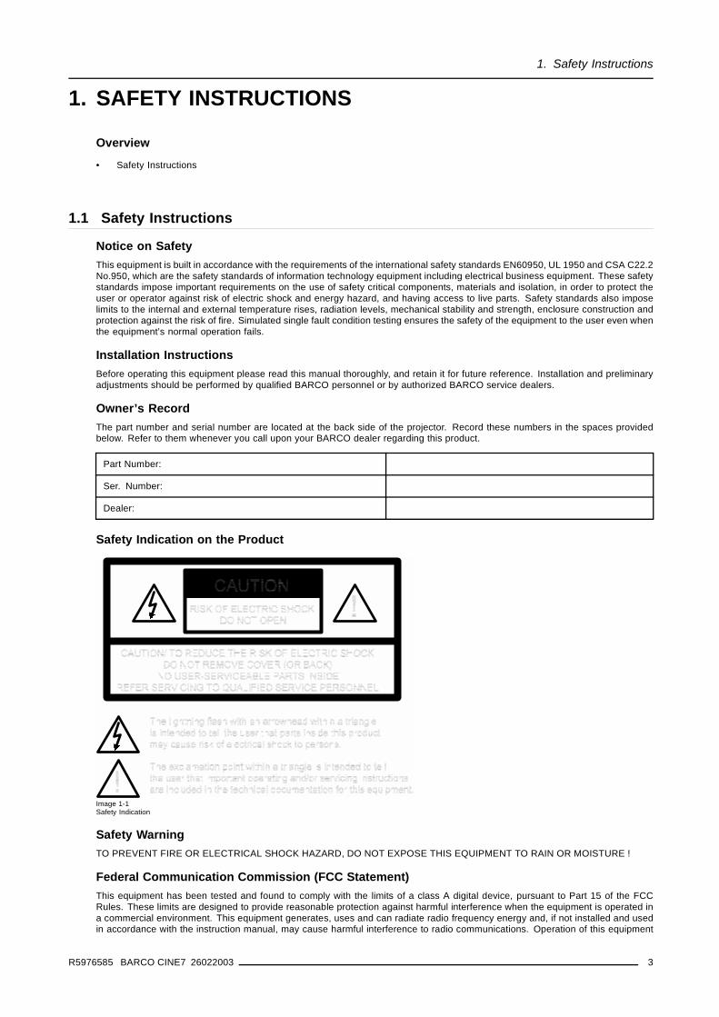
Safety Indication on the Product
Image 1-1Safety Indication
Safety WarningTO PREVENT FIRE OR ELECTRICAL SHOCK HAZARD, DO NOT EXPOSE THIS EQUIPMENT TO RAIN OR MOISTURE !
Federal Communication Commission (FCC Statement)This equipment has been tested and found to comply with the limits of a class A digital device, pursuant to Part 15 of the FCCRules. These limits are designed to provide reasonable protection against harmful interference when the equipment is operated ina commercial environment. This equipment generates, uses and can radiate radio frequency energy and, if not installed and usedin accordance with the instruction manual, may cause harmful interference to radio communications. Operation of this equipment
R5976585 BARCO CINE7 26022003 3
1. Safety Instructions
in a residential area is likely to cause harmful interference in which case the user will be required to correct the interference at hisown expense.
The use of shielded cables is required to comply within the limits of Part 15 of FCC rules and EN55022.
• All the safety and operating instructions should be read before using this unit.• The safety and operating instructions manual should be retained for future reference.• All warnings on the equipment and in the documentation manuals should be adhered to.• All instructions for operating and use of this equipment must be followed precisely.
On Safety
• This product should be operated from an AC power source. Power input is autoranging from 90 V to 230V.• All equipment in the system is equipped with a 3-wire grounding plug, a plug having a third (grounding) pin. This plug will only
fit into a grounding-type power outlet. This is a safety feature. If you are unable to insert the plug into the outlet, contact yourelectrician to replace your obsolete outlet. Do not defeat the purpose of the grounding-type plug.
• Do not allow anything to rest on the power cord. Do not locate this product where persons will walk on the cord. To disconnectthe cord, pull it out by the plug. Never pull the cord itself.
• If an extension cord is used with this product, make sure that the total of the ampere ratings on the products plugged into theextension cord does not exceed the extension cord ampere rating.
• Never push objects of any kind into this product through cabinet slots as they may touch dangerous voltage points or short outparts that could result in a risk of fire or electrical shock.
• Never spill liquid of any kind on the product. Should any liquid or solid object fall into the cabinet, unplug the set and have itchecked by qualified service personnel before resuming operations.
• Lightning - For added protection for this video product during a lightning storm, or when it is left unattended and unused forlong periods of time, unplug it from the wall outlet. This will prevent damage to the projector due to lightning and AC power-linesurges.
• The wires of the main lead are colored in accordance with the following code.
Image 1-2Power cord plugs
This apparatus must be grounded (earthed) via the supplied 3 conductor AC power cable. If the suppliedpower cable is not the correct one, consult your dealer.
Caution on Fire HazardDO NOT PLACE FLAMMABLE OR COMBUSTIBLE MATERIALS NEAR THE PROJECTOR !
BARCO large screen projection products are designed and manufactured to meet the most stringent safety regulations. This pro-jector radiates heat on its external surfaces and from ventilation ducts during normal operation, which is both normal and safe.Exposing flammable or combustible materials to the close proximity of this projector could result in the spontaneous ignition of thatmaterial, resulting in a fire. For this reason, it is absolutely necessary to leave an "exclusion zone" around all external surfaces of theprojector whereby no flammable or combustible materials are present. The exclusion zone must be not less that 10 cm (4") for BarcoRetro Projectors. Do not cover the projector with any material while the projector is in operation. Keep flammable and combustiblematerials away from the projector at all times. Mount the projector is a well ventilated area away from sources of ignition and outof direct sun light. Never expose the projector to rain or excessive moisture. In the event of fire, use sand, CO2, or dry powder fireextinguishers; never use water on an electrical fire. Always have service performed on this projector by authorized BARCO servicepersonnel. Always insist on genuine BARCO replacement parts. Never use non-BARCO replacement parts as they may degradethe safety of this projector.
4 R5976585 BARCO CINE7 26022003
1. Safety Instructions
On Installation
• Do not place this equipment on an unstable cart, stand, or table. The product may fall, causing serious damage to it.• Do not use this equipment near water.• Slots and openings in the cabinet and the back or bottom are provided for ventilation; to ensure reliable operation of the product
and to protect it from overheating, these openings must not be blocked or covered. The openings should never be blocked byplacing the product on a bed, sofa, rug, or other similar surface. This product should never be placed near or over a radiator orheat register. The projector should not be placed in a built-in installation or enclosure unless proper ventilation is provided.
• Do not block the projector cooling fans or free air movement under and around the projector. Loose papers or other objectsmay not be nearer to the projector than 4" on any side.
On ServicingDo not attempt to service this product yourself, as opening or removing covers may expose you to dangerous voltage potentials andrisk of electric shock!
Refer all servicing to qualified service personnel.
Unplug this product from the wall outlet and refer servicing to qualified service personnel under the following conditions:• When the power cord or plug is damaged or frayed.• If liquid has been spilled into the equipment.• If the product has been exposed to rain or water.• If the product does not operate normally when the operating instructions are followed. Adjust only those controls that are
covered by the operating instructions since improper adjustment of the other controls may result in damage and will oftenrequire extensive work by a qualified technician to restore the product to normal operation.
• If the product has been dropped or the cabinet has been damaged.• If the product exhibits a distinct change in performance, indicating a need for service.• Replacement parts: When replacement parts are required, be sure the service technician has used original BARCO replace-
ment parts or authorized replacement parts which have the same characteristics as the BARCO original part. Unauthorizedsubstitutions may result in degraded performance and reliability, fire, electric shock or other hazards. Unauthorized substitu-tions may void warranty.
• Safety check: Upon completion of any service or repairs to this projector, ask the service technician to perform safety checksto determine that the product is in proper operating condition.
On CleaningUnplug this product from the wall outlet before cleaning. Do not use liquid cleaners or aerosol cleaners. Use a damp cloth forcleaning. To keep the cabinet looking brand-new, periodically clean it with a soft cloth. Stubborn stains may be removed with a clothlightly dampened with mild detergent solution. Never use strong solvents, such as thinner or benzine, or abrasive cleaners, sincethese will damage the cabinet. To ensure the highest optical performance and resolution, the projection lenses are specially treatedwith an anti-reflective coating, therefore, avoid touching the lens. To remove dust on the lens, use a soft dry cloth. Do not use adamp cloth, detergent solution, or thinner.
On RepackingSave the original shipping carton and packing material; they will come in handy if you ever have to ship your equipment. For maxi-mum protection, repack your set as it was originally packed at the factory.
On IlluminationIn order to obtain the best quality for the projected image, it is essential that the ambient light which is allowed to fall on the screen bekept to an absolute minimum. When installing the projector and screen, care must be taken to avoid exposure to ambient light directlyon the screen. Avoid adverse illumination on the screen from direct sunlight or fluorescent lighting fixtures. The use of controlledambient lighting, such as incandescent spot light or a dimmer, is recommended for proper room illumination. Where possible, careshould also be taken to ensure that the floors and walls of the room in which the projector is to be installed are non-reflecting, darksurfaces. Brighter surfaces will tend to reflect and diffuse the ambient light and hence reduce the contrast of the projected image onthe screen.
R5976585 BARCO CINE7 26022003 5

1. Safety Instructions
6 R5976585 BARCO CINE7 26022003
2. Packaging and Dimensions
2. PACKAGING AND DIMENSIONS
2.1 Projector Packaging
Way of PackagingThe projector is packed in a carton box. To provide protection during transportation, the projector is surrounded with foam. Thepackage is secured with banding and fastening clips.
To unpack1. Release the fastening clips.
2. Remove the banding. Handle as shown in the drawing. (image 2-1)
3. Take the projector out of its shipping carton and place it on a table.
Image 2-1
Save the original shipping carton and packing material, they will be necessary if you ever have to ship yourprojector. For maximum protection, repack your projector as it was originally packed at the factory.
2.2 Box ContentContent
• 1 Barco Cine7• 1 Remote Control Unit + 2 batteries (1.5 V)• 1 Power Cord with outlet plug type CEE7• 1 Power Cord with outlet plug ANSI 73.11• 1 Installation Manual• 1 Owner’s Manual• 1 Adjustment manual IRIS• 1 CDROM
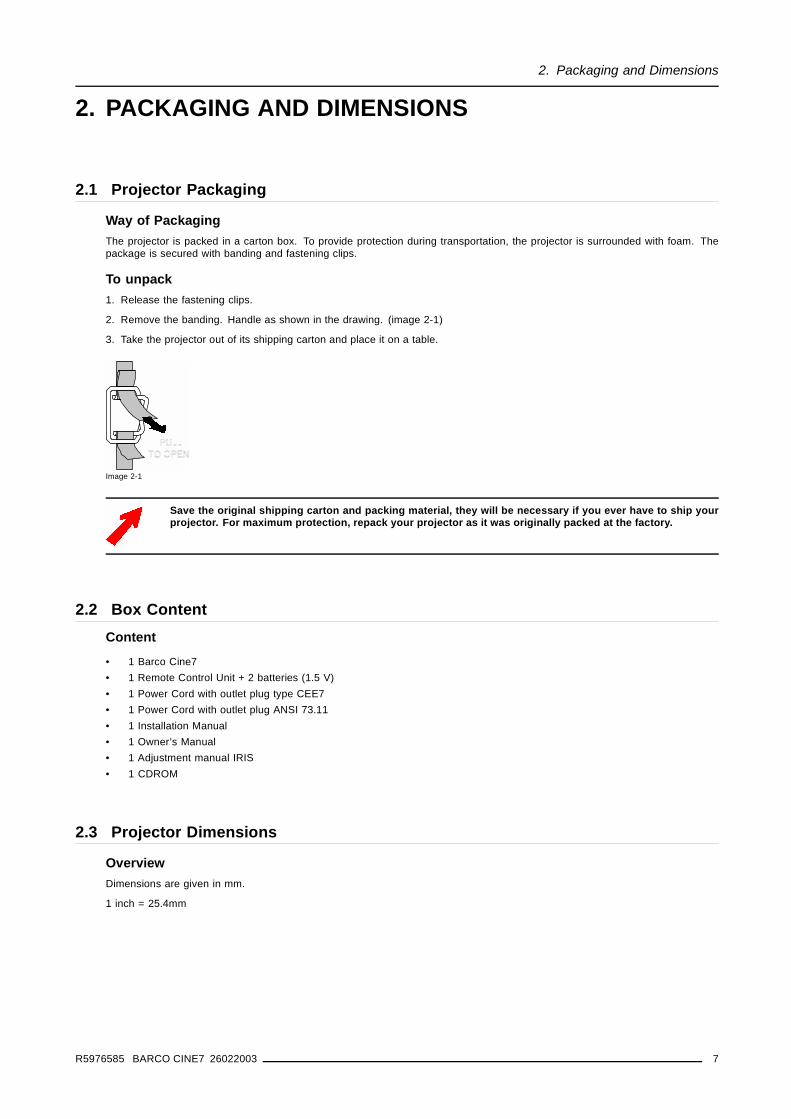
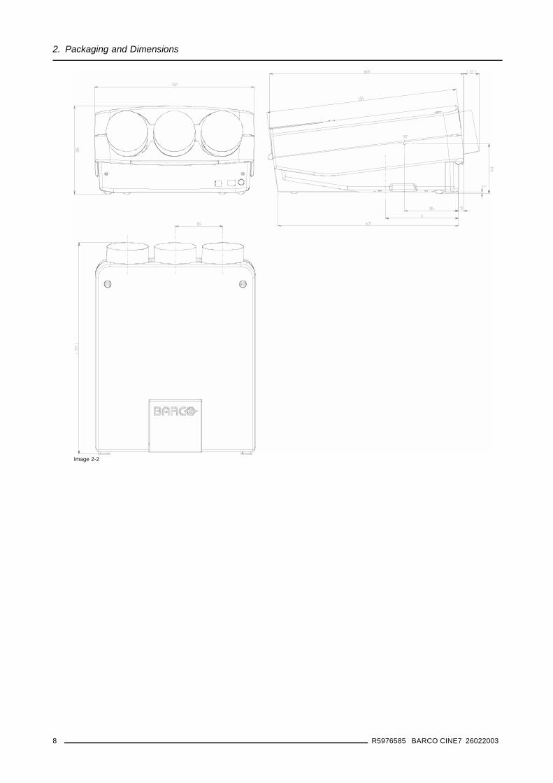
2.3 Projector Dimensions
OverviewDimensions are given in mm.
1 inch = 25.4mm
R5976585 BARCO CINE7 26022003 7
2. Packaging and Dimensions
Image 2-2
8 R5976585 BARCO CINE7 26022003
3. Installation Guidelines
3. INSTALLATION GUIDELINES
Overview
• General Installation Guidelines• Configuration• Lens Formulas• Scan Adaptation
3.1 General Installation GuidelinesAmbient temperature checkCareful consideration of things such as image size, ambient light level, projector placement and type of screen to use are critical tothe optimum use of the projection system.
Max. ambient temperature : 40 C or 104 F
Min. ambient temperature : 0 C or 32 F
The projector will not operate if ambient air temperature falls outside this range (0 C- 40 C or 32 F-104 F).
Humidity ConditionsStorage: 0 to 98 % RH Non-condensing
Operation: 0 to 95 % RH Non-condensing
EnvironmentDo not install the projection system in a site near heat sources such as radiators or air ducts, or in a place subject to direct sunlight,excessive dust or humidity. Be aware that room heat rises to the ceiling; check that temperature near the installation site is notexcessive.
Harmful Environmental Contamination Precaution.
Environment condition checkA projector must always be mounted in a manner which ensures the free flow of clean air into the projectors ventilation inlets. Forinstallations in environments where the projector is subject to airborne contaminants such as that produced by smoke machines orsimilar (these deposit a thin layer of greasy residue upon the projectors internal optics and imaging electronic surfaces, degradingperformance), then it is highly advisable and desirable to have this contamination removed prior to it reaching the projectors cleanair supply. Devices or structures to extract or shield contaminated air well away from the projector are a prerequisite, if this is not afeasible solution then measures to relocate the projector to a clean air environment should be considered.
Only ever use the manufactures recommended cleaning kit which has been specifically designed for cleaning optical parts, neveruse industrial strength cleaners on a projectors optics as these will degrade optical coatings and damage sensitive optoelectronicscomponents. Failure to take suitable precautions to protect the projector from the effects of persistent and prolonged air contami-nants will culminate in extensive and irreversible ingrained optical damage. At this stage cleaning of the internal optical units will benon-effective and impracticable. Damage of this nature is under no circumstances covered under the manufactures warranty andmay deem the warranty null and void. In such a case the client shall be held solely responsible for all costs incurred during anyrepair. It is the clients responsibility to ensure at all times that the projector is protected from the harmful effects of hostile airborneparticles in the environment of the projector. The manufacture reserves the right to refuse repair if a projector has been subject towillful neglect, abandon or improper use.
What about Ambient Light ?The ambient light level of any room is made up of direct or indirect sunlight and the light fixtures in the room. The amount of ambientlight will determine how bright the image will appear. So, avoid direct light on the screen. Windows that face the screen should becovered by opaque drapery while the set is being viewed. It is desirable to install the projection system in a room whose walls andfloor are of non-reflecting material. The use of recessed ceiling lights and a method of dimming those lights to an acceptable levelis also important. Too much ambient light will ‘wash out’ of the projected image. This appears as less contrast between the darkestand lightest parts of the image. With bigger screens, the ‘wash out’ becomes more important. As a general rule, darken the room tothe point where there is just sufficient light to read or write comfortably. Spot lighting is desirable for illuminating small areas so thatinterference with the screen is minimal.
Which Screen Type ?There are two major categories of screens used for projection equipment. Those used for front projected images and those for rearprojection applications.
R5976585 BARCO CINE7 26022003 9
3. Installation Guidelines
Screens are rated by how much light they reflect (or transmit in the case of rear projection systems) given a determined amountof light projected toward them. The ‘GAIN’ of a screen is the term used. Front and rear screens are both rated in terms of gain.The gain of screens range from a white matte screen with a gain of 1 (x1) to a brushed aluminized screen with a gain of 10 (x10)or more. The choice between higher and lower gain screens is largely a matter of personal preference and another considerationcalled the Viewing angle. In considering the type of screen to choose, determine where the viewers will be located and go for thehighest gain screen possible. A high gain screen will provide a brighter picture but reduce the viewing angle. For more informationabout screens, contact your local screen supplier.
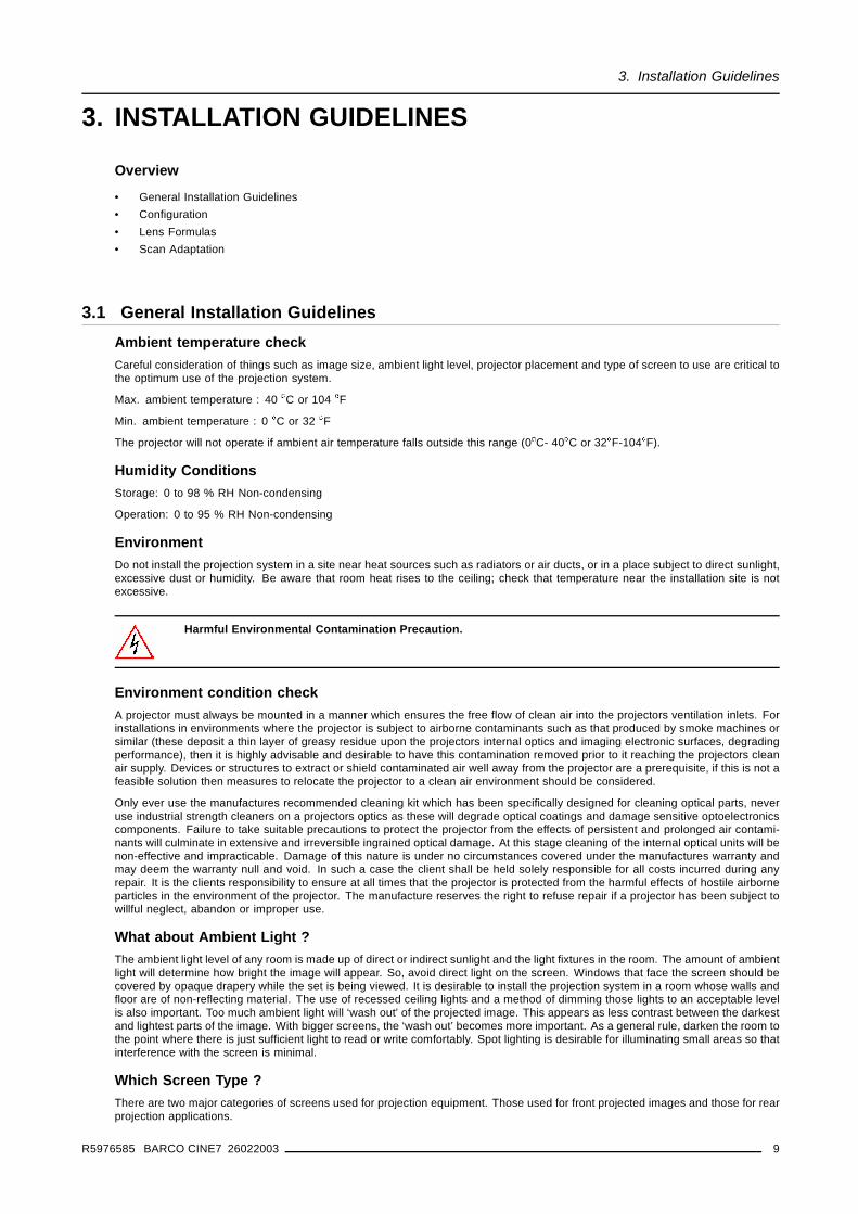
Image SizingThe projector is designed for projecting an image width from 1.4m (4.6’) to 7m (23’)The projector leaves the BARCO factory, adjustedas a Front/Ceiling projector for a screen width of 2400 mm (94.5 inch) with an aspect ratio of 4 by 3 (The projector can be factoryaligned in other configurations if ordered).
Image 3-1Image Sizing
Changing the image size from the projector preset size requires a realignment of the projector.
3.2 Configuration
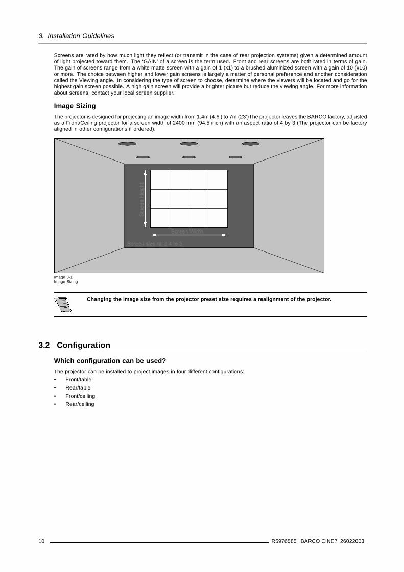
Which configuration can be used?The projector can be installed to project images in four different configurations:• Front/table• Rear/table• Front/ceiling• Rear/ceiling
10 R5976585 BARCO CINE7 26022003
3. Installation Guidelines
Image 3-2Possible configurations
Positioning the projector
The projector should be installed perpendicular with the screen on a distance PD and water leveled in bothdirections.
R5976585 BARCO CINE7 26022003 11
3. Installation Guidelines
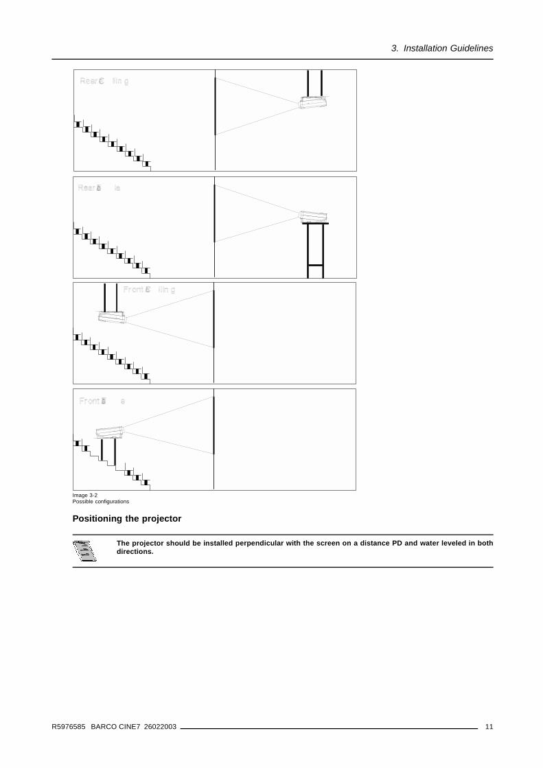
Image 3-3Projector positioning
B Distance between ceiling and top of the screenA Correction value, extra value to be added to B to obtain the correct installation position. (In some cases the A value can be
negative).CD Total distance between projector and distance.SW Screen widthPD Perpendicular distance between screen and projector.
CD = A + B. When the result is negative, enlarge the distance between ceiling and top of the screen, mount screen lower, until CDbecomes zero or positive)
3.3 Lens FormulasLens FormulasThe lens formulas should be used to calculate the ideal projector distance:
Lens type HD145
PD[meter] = 1.2642 x SW[meter] + 0.2156 A[cm] = 12 x SW[meter] - 22.88
PD[inch] = 1.2642 x SW[inch] + 8.48 A[inch] = 0.12 x SW[inch] - 9
Max phosphor width on CRT = 11cm (4.33 inch).
3.4 Scan Adaptation
Overview• Access to the scan controls• Scan Inversion
12 R5976585 BARCO CINE7 26022003
3. Installation Guidelines
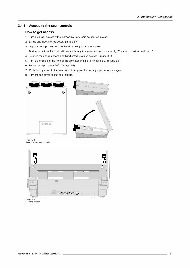
3.4.1 Access to the scan controls
How to get access1. Turn both lock screws with a screwdriver or a coin counter clockwise.
2. Lift up and pivot the top cover. (image 3-4)
3. Support the top cover with the hand, no support is incorporated.
During some installations it will become handy to remove the top cover totally. Therefore, continue with step 6.
4. To open the chassis, loosen both indicated retaining screws. (image 3-5)
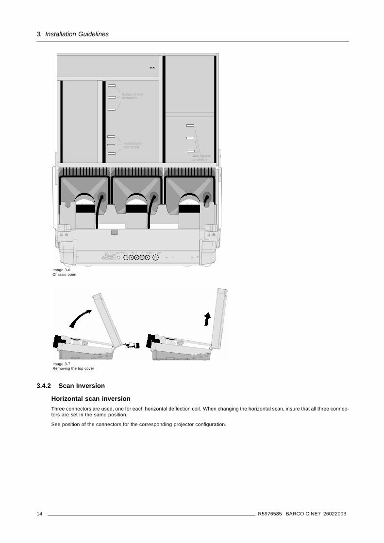
5. Turn the chassis to the front of the projector until it grips in its locks. (image 3-6)
6. Pivote the top cover ± 60 . (image 3-7)
7. Push the top cover to the front side of the projector until it jumps out of its hinges.
8. Turn the top cover till 90 and lift it up.
Image 3-4Access to the scan controls
Image 3-5Opening chassis
R5976585 BARCO CINE7 26022003 13
3. Installation Guidelines
Image 3-6Chassis open
Image 3-7Removing the top cover
3.4.2 Scan Inversion
Horizontal scan inversionThree connectors are used, one for each horizontal deflection coil. When changing the horizontal scan, insure that all three connec-tors are set in the same position.
See position of the connectors for the corresponding projector configuration.
14 R5976585 BARCO CINE7 26022003
3. Installation Guidelines
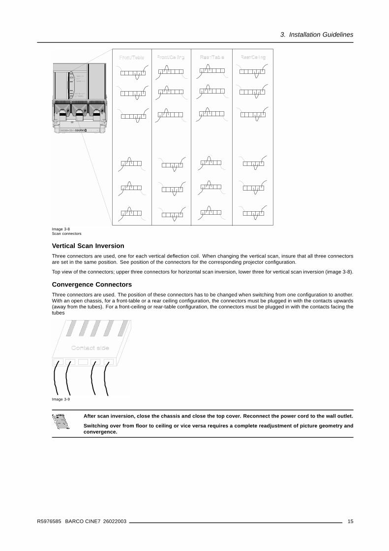
Image 3-8Scan connectors
Vertical Scan InversionThree connectors are used, one for each vertical deflection coil. When changing the vertical scan, insure that all three connectorsare set in the same position. See position of the connectors for the corresponding projector configuration.
Top view of the connectors; upper three connectors for horizontal scan inversion, lower three for vertical scan inversion (image 3-8).
Convergence ConnectorsThree connectors are used. The position of these connectors has to be changed when switching from one configuration to another.With an open chassis, for a front-table or a rear ceiling configuration, the connectors must be plugged in with the contacts upwards(away from the tubes). For a front-ceiling or rear-table configuration, the connectors must be plugged in with the contacts facing thetubes
Image 3-9
After scan inversion, close the chassis and close the top cover. Reconnect the power cord to the wall outlet.
Switching over from floor to ceiling or vice versa requires a complete readjustment of picture geometry andconvergence.
R5976585 BARCO CINE7 26022003 15
3. Installation Guidelines
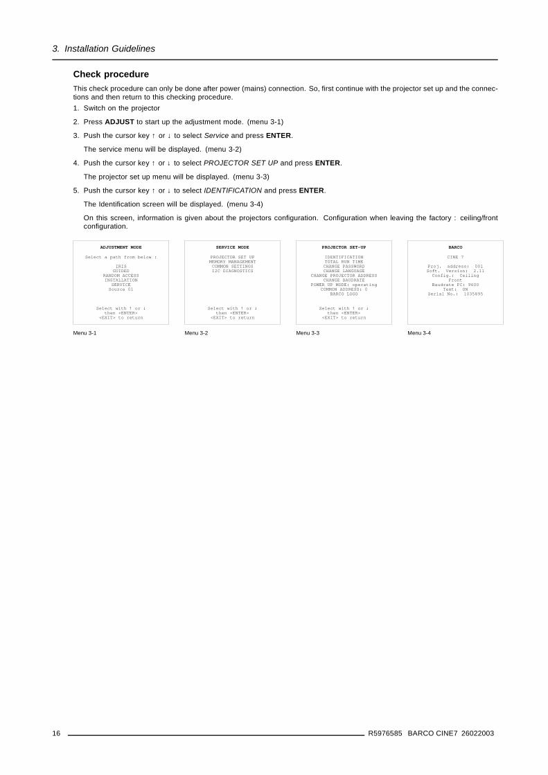
Check procedureThis check procedure can only be done after power (mains) connection. So, first continue with the projector set up and the connec-tions and then return to this checking procedure.1. Switch on the projector
2. Press ADJUST to start up the adjustment mode. (menu 3-1)
3. Push the cursor key ↑ or ↓ to select Service and press ENTER.
The service menu will be displayed. (menu 3-2)
4. Push the cursor key ↑ or ↓ to select PROJECTOR SET UP and press ENTER.
The projector set up menu will be displayed. (menu 3-3)
5. Push the cursor key ↑ or ↓ to select IDENTIFICATION and press ENTER.
The Identification screen will be displayed. (menu 3-4)
On this screen, information is given about the projectors configuration. Configuration when leaving the factory : ceiling/frontconfiguration.
ADJUSTMENT MODE
Select a path from below :
IRISGUIDED
RANDOM ACCESSINSTALLATION
SERVICESource 01
Select with ↑ or ↓then <ENTER>
<EXIT> to return
Menu 3-1
SERVICE MODE
PROJECTOR SET UPMEMORY MANAGEMENTCOMMON SETTINGSI2C DIAGNOSTICS
Select with ↑ or ↓then <ENTER>
<EXIT> to return
Menu 3-2
PROJECTOR SET-UP
IDENTIFICATIONTOTAL RUN TIMECHANGE PASSWORDCHANGE LANGUAGE
CHANGE PROJECTOR ADDRESSCHANGE BAUDRATE
POWER UP MODE: operatingCOMMON ADDRESS: 0
BARCO LOGO
Select with ↑ or ↓then <ENTER>
<EXIT> to return
Menu 3-3
BARCO
CINE 7
Proj. address: 001Soft. Version: 2.11
Config.: CeilingFront
Baudrate PC: 9600Text: ON
Serial No.: 1035895
Menu 3-4
16 R5976585 BARCO CINE7 26022003
4. Projector Set up
4. PROJECTOR SET UP
Overview
• Password strap
4.1 Password strap
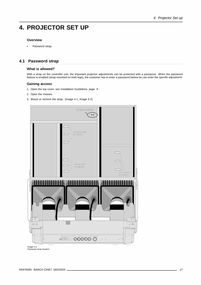
What is allowed?With a strap on the controller unit, the important projector adjustments can be protected with a password. When the passwordfeature is enabled (strap mounted on both legs), the customer has to enter a password before he can enter the specific adjustment.
Gaining access1. Open the top cover, see Installation Guidelines, page 9 .
2. Open the chassis.
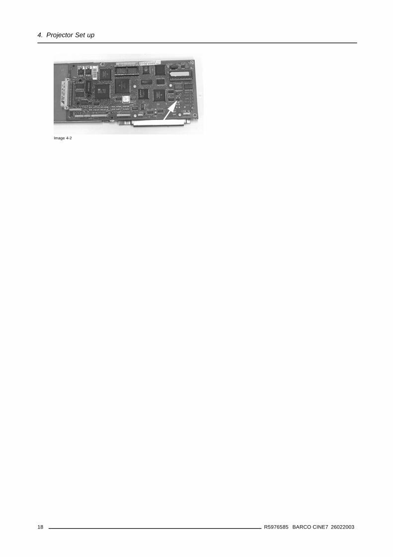
3. Mount or remove the strap. (image 4-1, image 4-2)
Image 4-1Password strap location
R5976585 BARCO CINE7 26022003 17
4. Projector Set up
Image 4-2
18 R5976585 BARCO CINE7 26022003
5. Installation Adjustment
5. INSTALLATION ADJUSTMENT
Overview
• Entering the Service menus• Starting up the Installation Adjustment Mode• Password Protection• Overview Installation mode• Scheimpflug Adjustment• Optical Lens Focusing• Electrical focusing• Raster Centering• CRT Projection Angle Adjustment
5.1 Entering the Service menus
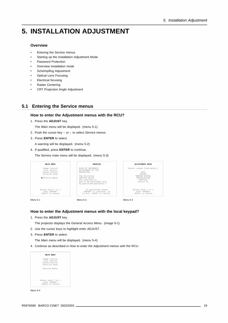
How to enter the Adjustment menus with the RCU?1. Press the ADJUST key.
The Main menu will be displayed. (menu 5-1)
2. Push the cursor key ↑ or ↓ to select Service menus.
3. Press ENTER to select.
A warning will be displayed. (menu 5-2)
4. If qualified, press ENTER to continue.
The Service main menu will be displayed. (menu 5-3)
MAIN MENU
Image controlIris controlSound controlFunction keys
Service menus
Select with ↑ or ↓then <ENTER>
<EXIT> to return
Menu 5-1
WARNING
RISK OF INCORRECTADJUSTMENT OF THEPROJECTOR.
The followingSERVICE menusare reserved to,and to be performed onlyby qualified personnel !
If qualified, press<ENTER> to continue, or
if not, <EXIT> to return.
Menu 5-2
ADJUSTMENT MODE
Select a path from below :
IRISGUIDED
RANDOM ACCESSINSTALLATION
SERVICESource 01
Select with ↑ or ↓then <ENTER>
<EXIT> to return
Menu 5-3
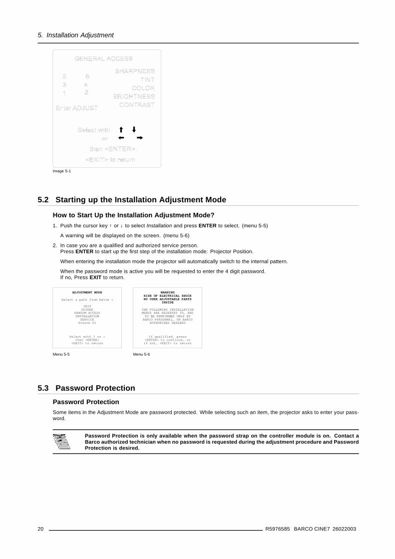
How to enter the Adjustment menus with the local keypad?1. Press the ADJUST key.
The projector displays the General Access Menu. (image 5-1)
2. Use the cursor keys to highlight enter ADJUST.
3. Press ENTER to select.
The Main menu will be displayed. (menu 5-4)
4. Continue as described in How to enter the Adjustment menus with the RCU.
MAIN MENU
Image controlIris controlSound controlFunction keys
Service menus
Select with ↑ or ↓then <ENTER>
<EXIT> to return
Menu 5-4
R5976585 BARCO CINE7 26022003 19
5. Installation Adjustment
Image 5-1
5.2 Starting up the Installation Adjustment Mode
How to Start Up the Installation Adjustment Mode?1. Push the cursor key ↑ or ↓ to select Installation and press ENTER to select. (menu 5-5)
A warning will be displayed on the screen. (menu 5-6)
2. In case you are a qualified and authorized service person.Press ENTER to start up the first step of the installation mode: Projector Position.
When entering the installation mode the projector will automatically switch to the internal pattern.
When the password mode is active you will be requested to enter the 4 digit password.If no, Press EXIT to return.
ADJUSTMENT MODE
Select a path from below :
IRISGUIDED
RANDOM ACCESSINSTALLATION
SERVICESource 01
Select with ↑ or ↓then <ENTER>
<EXIT> to return
Menu 5-5
WARNINGRISK OF ELECTRICAL SHOCKNO USER ADJUSTABLE PARTS
INSIDE
THE FOLLOWING INSTALLATIONMENUS ARE RESERVED TO, ANDTO BE PERFORMED ONLY BY
BARCO PERSONNEL, OR BARCOAUTHORIZED DEALERS
If qualified, press<ENTER> to continue, orif not, <EXIT> to return
Menu 5-6
5.3 Password ProtectionPassword ProtectionSome items in the Adjustment Mode are password protected. While selecting such an item, the projector asks to enter your pass-word.
Password Protection is only available when the password strap on the controller module is on. Contact aBarco authorized technician when no password is requested during the adjustment procedure and PasswordProtection is desired.
20 R5976585 BARCO CINE7 26022003
5. Installation Adjustment
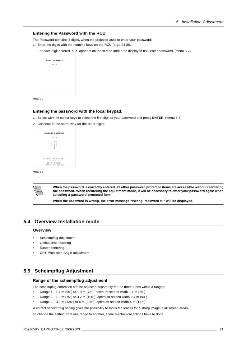
Entering the Password with the RCUThe Password contains 4 digits, when the projector asks to enter your password:1. Enter the digits with the numeric keys on the RCU (e.g.: 2319).
For each digit entered, a ’X’ appears on the screen under the displayed text ’enter password’ (menu 5-7)
enter password
XXXX
Menu 5-7
Entering the password with the local keypad.1. Select with the cursor keys to select the first digit of your password and press ENTER. (menu 5-8)
2. Continue in the same way for the other digits.
COMPOSE PASSWORD
????
7 8 94 5 61 2 3
0
Select with ↑ or ↓← or →
then <ENTER><EXIT> to return
Menu 5-8
When the password is correctly entered, all other password protected items are accessible without reenteringthe password. When reentering the adjustment mode, it will be necessary to enter your password again whenselecting a password protected item.
When the password is wrong, the error message “Wrong Password !!!” will be displayed.
5.4 Overview Installation modeOverview
• Scheimpflug adjustment• Optical lens focusing• Raster centering• CRT Projection Angle adjustment
5.5 Scheimpflug Adjustment
Range of the scheimpflug adjustmentThe scheimpfug correction can be adjusted separately for the three tubes within 3 ranges:• Range 1 : 1.4 m (55") to 1.9 m (75"), optimum screen width 1.4 m (55")• Range 2 : 1.9 m (75") to 3.2 m (126"), optimum screen width 2.4 m (94")• Range 3 : 3.2 m (126") to 6 m (236"), optimum screen width 4 m (157")
A correct scheimpfug setting gives the possibility to focus the lenses for a sharp image in all screen areas.
To change the setting from one range to another, some mechanical actions have to done.
R5976585 BARCO CINE7 26022003 21
5. Installation Adjustment
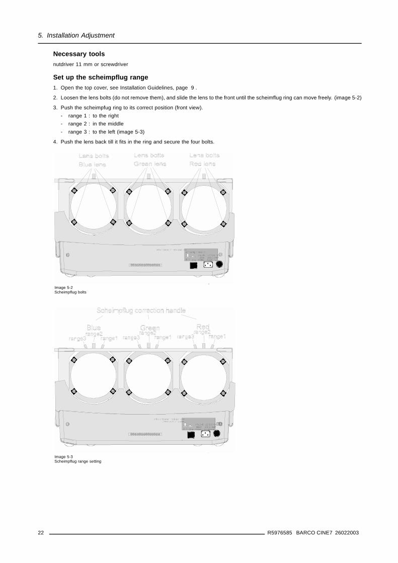
Necessary toolsnutdriver 11 mm or screwdriver
Set up the scheimpflug range1. Open the top cover, see Installation Guidelines, page 9 .
2. Loosen the lens bolts (do not remove them), and slide the lens to the front until the scheimflug ring can move freely. (image 5-2)
3. Push the scheimpfug ring to its correct position (front view).- range 1 : to the right- range 2 : in the middle- range 3 : to the left (image 5-3)
4. Push the lens back till it fits in the ring and secure the four bolts.
Image 5-2Scheimpflug bolts
Image 5-3Scheimpflug range setting
22 R5976585 BARCO CINE7 26022003
5. Installation Adjustment
5.6 Optical Lens Focusing
What can be done?The optical focusing procedure is performed separately for each lens. The appropriate CRT will be switched on as the user proceedsthrough the optical focusing adjustment sequence.
How to focus1. To focus the center, loosen the wing nut at the rear end of the lens.
2. Rotate the lens barrel until the center fo the image is clearly focussed.
3. Loosen the wing nut at the front end of the lens.
4. Rotate the lens barrel until the corners of the image are clearly focussed.Note: Repetition of these adjustments may be necessary to optimize optical focusing.
5. Press ENTER key to continue to the next color. (menu 5-9)
OPTICAL LENS FOCUSING
1. Loosen the nut on therear of the xxxx lens.Rotate the lens barrelto focus the center
of the image.Then tighten the nut.
2. Loosen the nut on thefront of the xxxx lens.
Rotate the frontsection of the lens to
focus the corners of theimage. Then tighten the nut.
<ENTER> to continue<EXIT> to return
Menu 5-9
5.7 Electrical focusing
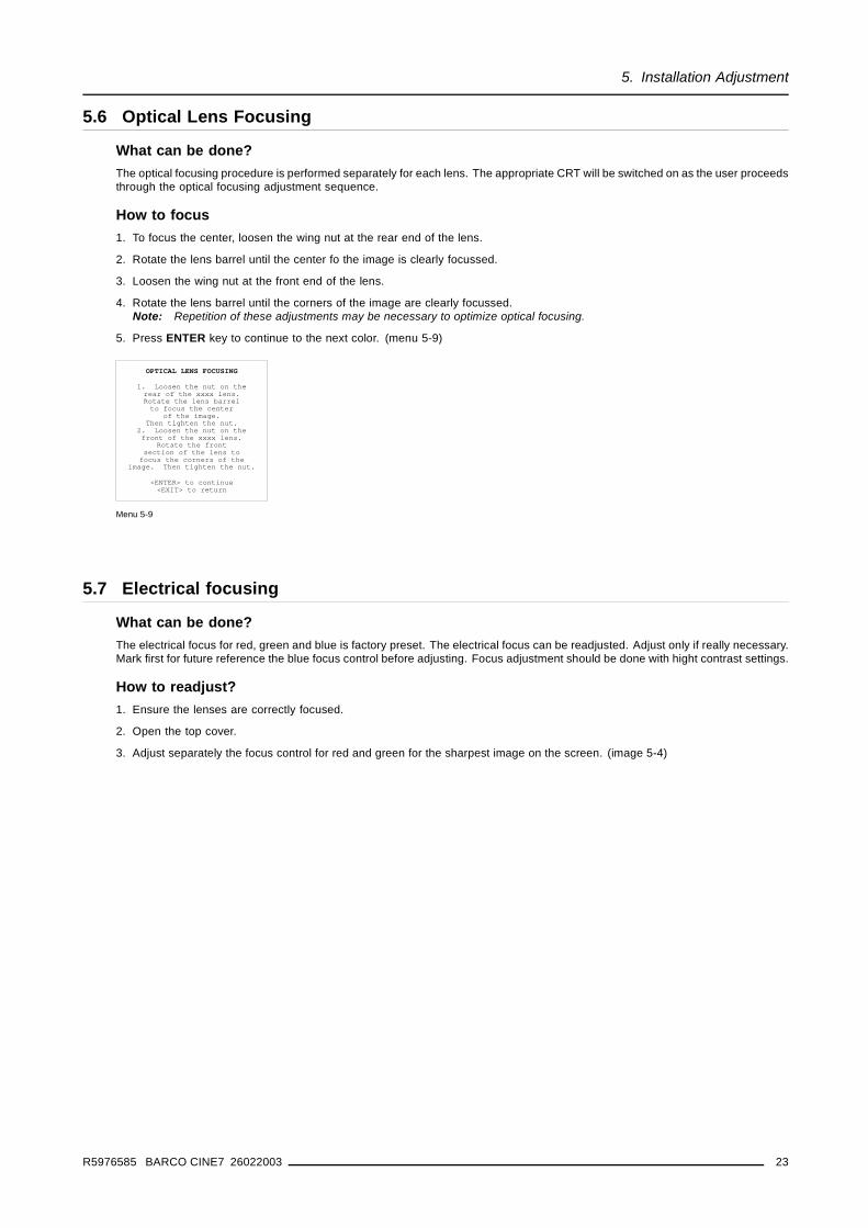
What can be done?The electrical focus for red, green and blue is factory preset. The electrical focus can be readjusted. Adjust only if really necessary.Mark first for future reference the blue focus control before adjusting. Focus adjustment should be done with hight contrast settings.
How to readjust?1. Ensure the lenses are correctly focused.
2. Open the top cover.
3. Adjust separately the focus control for red and green for the sharpest image on the screen. (image 5-4)
R5976585 BARCO CINE7 26022003 23
5. Installation Adjustment
Image 5-4Electrical focus adjustment
The blue focus has been factory adjusted for optimal color reproduction. Readjustment of the blue focus willeffect color temperature and color tracking.
5.8 Raster Centering
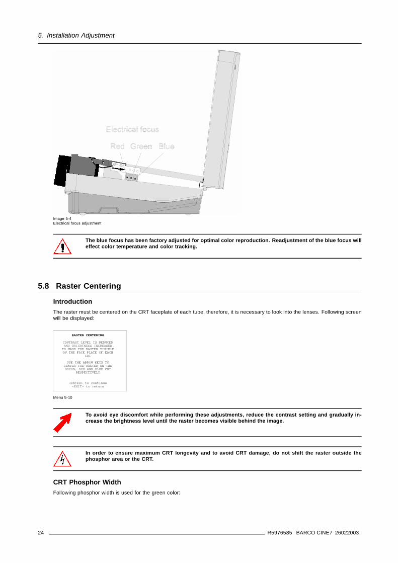
IntroductionThe raster must be centered on the CRT faceplate of each tube, therefore, it is necessary to look into the lenses. Following screenwill be displayed:
RASTER CENTERING
CONTRAST LEVEL IS REDUCEDAND BRIGHTNESS INCREASED
TO MAKE THE RASTER VISIBLEON THE FACE PLATE OF EACH
CRT
USE THE ARROW KEYS TOCENTER THE RASTER ON THEGREEN, RED AND BLUE CRT
RESPECTIVELY
<ENTER> to continue<EXIT> to return
Menu 5-10
To avoid eye discomfort while performing these adjustments, reduce the contrast setting and gradually in-crease the brightness level until the raster becomes visible behind the image.
In order to ensure maximum CRT longevity and to avoid CRT damage, do not shift the raster outside thephosphor area or the CRT.
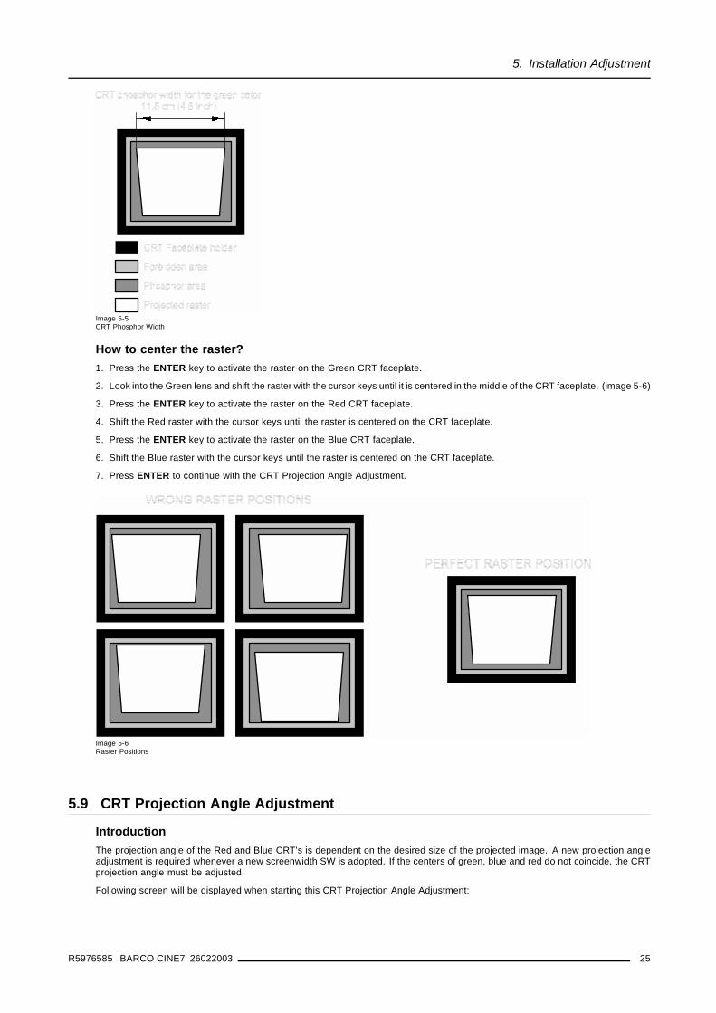
CRT Phosphor WidthFollowing phosphor width is used for the green color:
24 R5976585 BARCO CINE7 26022003
5. Installation Adjustment
Image 5-5CRT Phosphor Width
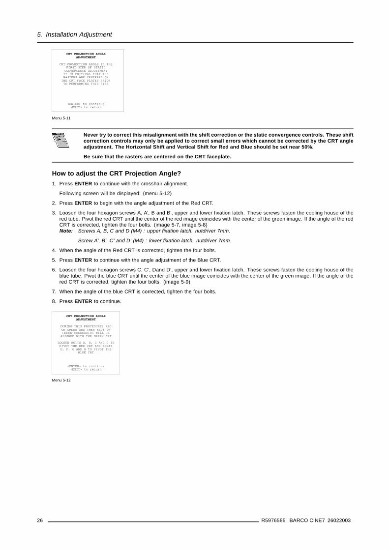
How to center the raster?1. Press the ENTER key to activate the raster on the Green CRT faceplate.
2. Look into the Green lens and shift the raster with the cursor keys until it is centered in the middle of the CRT faceplate. (image 5-6)
3. Press the ENTER key to activate the raster on the Red CRT faceplate.
4. Shift the Red raster with the cursor keys until the raster is centered on the CRT faceplate.
5. Press the ENTER key to activate the raster on the Blue CRT faceplate.
6. Shift the Blue raster with the cursor keys until the raster is centered on the CRT faceplate.
7. Press ENTER to continue with the CRT Projection Angle Adjustment.
Image 5-6Raster Positions
5.9 CRT Projection Angle Adjustment
IntroductionThe projection angle of the Red and Blue CRT’s is dependent on the desired size of the projected image. A new projection angleadjustment is required whenever a new screenwidth SW is adopted. If the centers of green, blue and red do not coincide, the CRTprojection angle must be adjusted.
Following screen will be displayed when starting this CRT Projection Angle Adjustment:
R5976585 BARCO CINE7 26022003 25
5. Installation Adjustment
CRT PROJECTION ANGLEADJUSTMENT
CRT PROJECTION ANGLE IS THEFIRST STEP OF STATIC
CONVERGENCE ADJUSTMENTIT IS CRITICAL THAT THERASTERS ARE CENTERED ON
THE CRT FACE PLATES PRIORTO PERFORMING THIS STEP
<ENTER> to continue<EXIT> to return
Menu 5-11
Never try to correct this misalignment with the shift correction or the static convergence controls. These shiftcorrection controls may only be applied to correct small errors which cannot be corrected by the CRT angleadjustment. The Horizontal Shift and Vertical Shift for Red and Blue should be set near 50%.
Be sure that the rasters are centered on the CRT faceplate.
How to adjust the CRT Projection Angle?1. Press ENTER to continue with the crosshair alignment.
Following screen will be displayed: (menu 5-12)
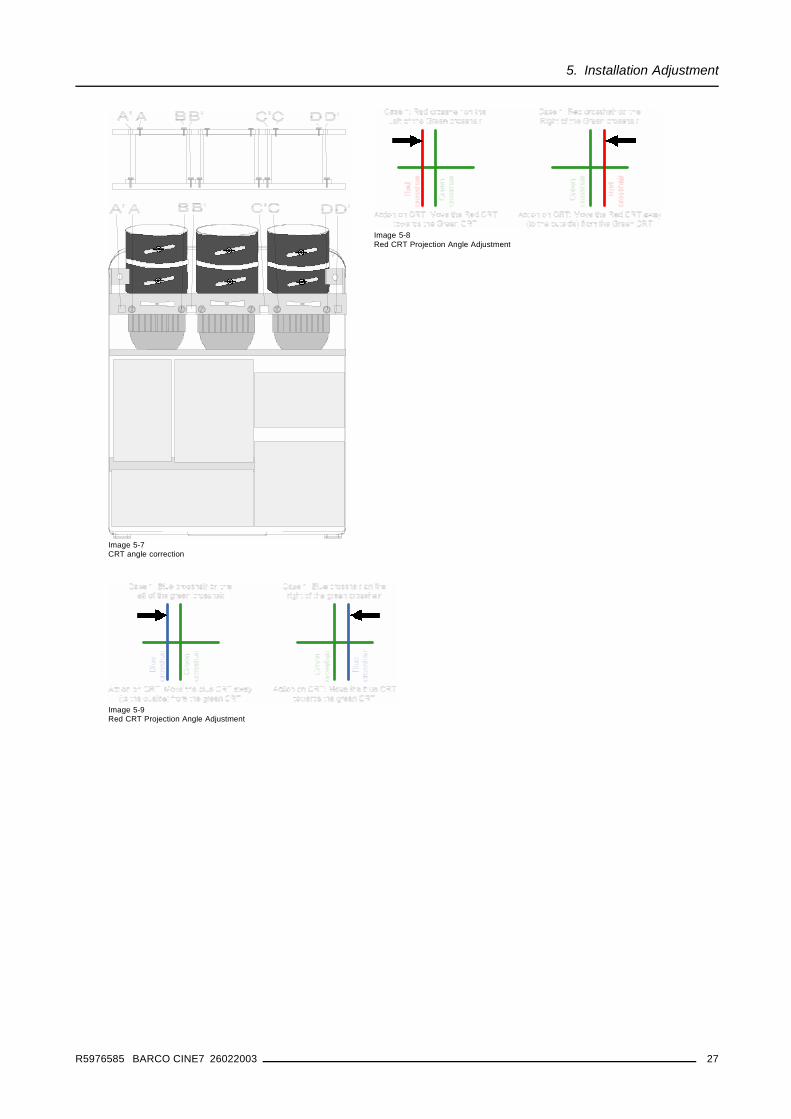
2. Press ENTER to begin with the angle adjustment of the Red CRT.
3. Loosen the four hexagon screws A, A’, B and B’, upper and lower fixation latch. These screws fasten the cooling house of thered tube. Pivot the red CRT until the center of the red image coincides with the center of the green image. If the angle of the redCRT is corrected, tighten the four bolts. (image 5-7, image 5-8)Note: Screws A, B, C and D (M4) : upper fixation latch. nutdriver 7mm.
Screw A’, B’, C’ and D’ (M4) : lower fixation latch. nutdriver 7mm.
4. When the angle of the Red CRT is corrected, tighten the four bolts.
5. Press ENTER to continue with the angle adjustment of the Blue CRT.
6. Loosen the four hexagon screws C, C’, Dand D’, upper and lower fixation latch. These screws fasten the cooling house of theblue tube. Pivot the blue CRT until the center of the blue image coincides with the center of the green image. If the angle of thered CRT is corrected, tighten the four bolts. (image 5-9)
7. When the angle of the blue CRT is corrected, tighten the four bolts.
8. Press ENTER to continue.
CRT PROJECTION ANGLEADJUSTMENT
DURING THIS PROCEDURE? REDON GREEN AND THEN BLUE ONGREEN CROSSHAIRS WILL BE
ALIGNED WITH THE GREEN CRT
LOOSEN BOLTS A, B, C AND D TOPIVOT THE RED CRT AND BOLTSE, F, G AND H TO PIVOT THE
BLUE CRT
<ENTER> to continue<EXIT> to return
Menu 5-12
26 R5976585 BARCO CINE7 26022003
5. Installation Adjustment
Image 5-7CRT angle correction
Image 5-8Red CRT Projection Angle Adjustment
Image 5-9Red CRT Projection Angle Adjustment
R5976585 BARCO CINE7 26022003 27

5. Installation Adjustment
28 R5976585 BARCO CINE7 26022003
6. G2 Adjustment
6. G2 ADJUSTMENT
6.1 Start up the G2 adjustment
Start up1. Enter the adjustment mode by pressing ADJUST. (menu 6-1)
2. Highlight Service.
3. Press ENTER to start up the service mode.
4. Highlight Common settings. (menu 6-2)
5. Press ENTER.
6. Highlight G2 adjust. (menu 6-3)
7. Press ENTER.
A safety notice will be displayed to warn the operator. (menu 6-4)
If you are qualified, press ENTER to continue with the G2 adjustment, otherwise press EXIT to return to the service menu. IfENTER is pressed, the G2 menu will be displayed (menu 6-5)
ADJUSTMENT MODE
Select a path from below :
IRISGUIDED
RANDOM ACCESSINSTALLATION
SERVICESource 01
Select with ↑ or ↓then <ENTER>
<EXIT> to return
Menu 6-1
SERVICE MODE
PROJECTOR SET UPMEMORY MANAGEMENTCOMMON SETTINGSI2C DIAGNOSTICS
Select with ↑ or ↓then <ENTER>
<EXIT> to return
Menu 6-2
COMMON SETTINGS
G2 ADJUSTMENTCRT RUN IN CYCLEPROJECTOR WARM UP
MEMORY BANKS
Select with ↑ or ↓then <ENTER>
<EXIT> to return
Menu 6-3
SAFETYNOTICE
RISK OF ELECTRICAL SHOCK
G2 ADJUSTMENT SHOULDBE PRERFORMED BY BARCO
AUTHORIZED DEALERS
IF QUALIFIED, PRESS<ENTER> to continue,or
If not, <EXIT> to return.
Menu 6-4
G2 ADJUSTMENT
REDABL: ON
Select color with ← or →<ENTER> to toggle ABL
<EXIT> to return
Menu 6-5
6.2 Adjusting the G2
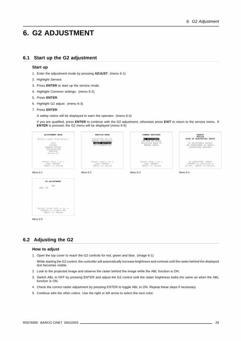
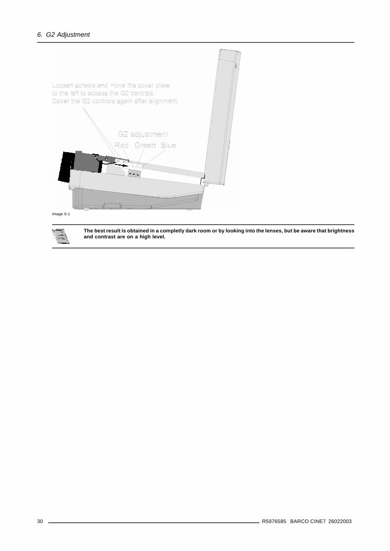
How to adjust1. Open the top cover to reach the G2 controls for red, green and blue. (image 6-1)
While starting the G2 control, the controller will automatically increase brightness and contrast until the raster behind the displayedtext becomes visible.
2. Look to the projected image and observe the raster behind the image while the ABL function is ON.
3. Switch ABL to OFF by pressing ENTER and adjust the G2 control until the raster brightness looks the same as when the ABLfunction is ON.
4. Check the correct raster adjustment by pressing ENTER to toggle ABL to ON. Repeat these steps if necessary.
5. Continue wiht the other colors. Use the right or left arrow to select the next color.
R5976585 BARCO CINE7 26022003 29
6. G2 Adjustment
Image 6-1
The best result is obtained in a completly dark room or by looking into the lenses, but be aware that brightnessand contrast are on a high level.
30 R5976585 BARCO CINE7 26022003
Revision Sheet
To:
Barco nv Home Cinema/DocumentationNoordlaan 5, B-8520 KuurnePhone: +32 56.36.84.30, Fax: +32 56.36.88.62E-mail: [email protected], Web: www.homecinema.barco.com
From:
Date:
Please correct the following points in this documentation (R5976585/00):
page wrong correct
R5976585 BARCO CINE7 26022003


