22
Barcol-Air Radiant Ceiling BRC

11.2
005
Barcol-Air Radiant Ceiling BRC

1.1
BENEFITS
• 100% reproducible perfor- mance due to factory �nished activation of panels.• The heat conducting rails are bonded to the reverse side of the panel utilizing a permanently elastic material which ensures a highly e�cient heat transfer and adds rigidity to the ceiling panel.• Minimal water resistance. Calibrated copper tubes 12 mm dia. (10 and 15 mm dia. also possible).• Fast and e�ective and economic installation through the use of push-on quick release couplings.• The greatest percentage of cooling is achieved by radiation ensuring a high comfort level.• Draught-free cooling in accordance with DIN, ISO and SIA standards.
APPLICATION
Due to the high cooling capaci-ty, the patented design and excellent acoustic qualities, the Barcol-Air radiant ceiling system type BRC provides the client and consultant, architect and the contractor with a highly �exible system. Barcol-Air Radiant Ceiling system can be used with any powder coated metal ceiling panel and is easily incorporated into either new or renovated buildings. It can be utilized in cellular and open plan o�ces, department stores, research and development laboratories as well as production and assembly areas.
TYPICAL PANEL DESIGN
Metal Ceiling Panelfig 1.1 Pos. 1The ceiling panel, normally manufactured from 0.027” thick zinc coated steel plate, powder coated approx. 80 µm thick to color code RAL9010 sfs (semi-matt �ne structure �nish), is perforated 0.098 inch dia. to provide 16 - 25% free area. Other colors, perforations and panel material are possible as supplied by most panel manufacturers.
Heat Conducting Railfig. 1.1 Pos. 2The heat conducting rails are manufactured from high precision extruded aluminum pro�les with a black anodized �nish. The rails are speci�cally designed to accommodate the calibrated copper tube.
Calibrated Copper Tubefig. 1.1 Pos. 3The standard diameter used is 12 mm. The high precision tube and the extruded rail are assembled under pressure, thereby creating a continuous contact between the two surfaces throughout their entire length.
Heat Conductive Permanent Bondingfig 1.1 Pos.4The aluminum heat conducting rails are secured to the reverse side of the ceiling panel by a unique bonding process. The technique utilizes a special permanently elastic material which ensures a highly e�cient heat transfer to the panel surface.
1.1
Acoustic Inlay fig 1.1 Pos. 5The acoustic inlay mineral �ber would be typically 1 1/5” thick with a density of 2 1/2 lb/sqft. The inlay is sealed in an air tight black plastic sheet, ensuring no �bers are being released. The chosen materials provide an optimum sound absorption. The acoustic performance of an inlay system is not a�ected by the depth of the void. If an acoustic �eece (which is available as an option) is used instead of inlay system, the acoustic performance is in�uenced by the depth of the void. (fig 1.1 Pos. 6)
1 2 3 4
5
6
2

2.1
3.1 10 11 12 14 5131 16 17
2.1
CEILING PANELS
�g. 2.1The dimensions of the ceiling panels can be chosen to suit the architectural design of the ceiling. Most panel dimensions produced by the panel manufacturers are possible. The standard distance between the heat conducting rails is 5.9 inches with copper tube dia.12 mm. The minimum distance from the edge of the panel is 2 inches. The distance between each rail can vary to allow for di�erent cooling capacities. Ceiling panel manufac-turers can incorporate a range of design options into the panel edge detail to accommodate a variety of mounting systems e.g. C-pro�le / Linear Grid / H-pro�le etc. Furthermore where the architectural design requires spaces between each panel, distance pads or space strips can be included to maintain uniformi-ty of appearance.
THE ARCHITECTURAL DESIGN OF THE CEILING
Almost any shape, preferably �at but also curved, can be chosen by the designers to accommodate the architectural requirements of the buildings.
fig. 3.1 A very typical design is shown in �g 3.1. Taking the window axis as a centerline, a support grid is mounted which in turn is used to retain the panel but also allows the mounting of the supports for the room dividing walls. This system is especially suitable for buildings in which a high degree of �exibility is required.
The number of active and inactive panels is governed by the cooling load for the area. Active and inactive look alike when viewed from the room. To allow for building tolerances, inactive panels are mounted at the edge of the room and cut to suit the room geometry. In o�ces where the cooling load is relatively low, the active panels are mounted in the window area where the largest heat input can be expected.
Since no restric-tions concerning the panel dimen-
sions exist, any building structure and architectural design in respect of ceilings can be
accommodated.
3
4.1
1 1/
4”
6” 0.2”0.2”
2 3/
4” 4”
sixa enozsixa enoz
ceiling panel linear grid ceiling panel
leveling nut
support bracket threaded rod 1/4”
Approx. 4 ft
0.2”
2 3/
4” 4”
1 1/
4”
lenap gnilieclenap gniliec
leveling nut
support bracket threaded rod 1/4” support bracket
Approx. 4 ft
double edging strip
ceiling panel
4.4
4.3
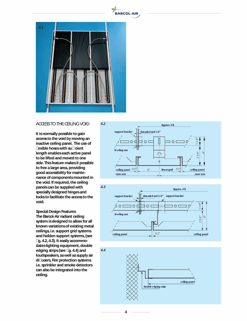
4.2ACCESS TO THE CEILING VOID
It is normally possible to gain access to the void by moving an inactive ceiling panel. The use of �exible hoses with su�cient length enables each active panel to be lifted and moved to one side. This feature makes it possible to free a large area, providing good accessibility for mainte-nance of components mounted in the void. If required, the ceiling panels can be supplied with specially designed hinges and locks to facilitate the access to the void.
Special Design Features The Barcol-Air radiant ceiling system is designed to allow for all known variations of existing metal ceilings, i.e. support grid systems and hidden support systems, (see �g. 4.2, 4.3). It easily accommo-dates lighting equipment, double edging strips (see �g. 4.4) and loudspeakers, as well as supply air di�users. Fire protection systems i.e. sprinkler and smoke detectors can also be integrated into the ceiling.
4

HOW TO DETERMINE THE SPECIFIC COOLING CAPACITY
Standard Cooling Capacity Fig. 5.1 shows the cooling capacity line determined in accordance with the DIN 4715-1 standards, part 1 as a function of the mean temperature difference ∆tm . The standard cooling capacity is related to applications with the following conditions: • room height of 8’-10’’• 70% active area • no fresh air supply from the ceiling• symmetric arrangement of the heat sources in the room• thermal storage of the building substance must not be considered• ceiling panels perforated; 16% free area The red line is valid for ceiling panels made of steel plate, 2.5” thick. The distance between the heat conducting rails is 5.9”. The
green line is valid for panels made of aluminum, 3.3‘’ thick. The distance between the heat con- ducting rails also at 5.9’’. The DIN test was carried out with heat conducting rails center to center 3.15’’. (sec. VF 99 K 24.1337). The standard cooling capacity can be increased to well above 63.4 Btuh/ft2 and still fulfill the DIN- ISO- and SIA standards concern-ing comfort condition in the room, with the aid of additional equip-ment installed in the void.
HOW TO DETERMINE THE MEAN TEMPERATURE DIFFERENCE ∆tm:
∆tm = (tR – ((twi + two)*0.5)
∆tm = mean temperature difference ˚FtR = room air temperature °F (dry bulb)twi = temperature water inlet °Ftwo = temperature water outlet °F
t
Whenever the difference between the room air- and the water outlet tempera-ture is less than 11˚F one has to use the logarithmic instead of the arithmetic average temperature difference.
∆tm = (two – twi)/ ln ((tR – twi) / (tR – two))
CORRECTION FACTORS FOR DIFFERENT APPLICATIONS
Combining the chilled ceiling with the fresh air inlet from the ceiling produces an increased air circulation thus increasing the specific cooling capacity up to 5%. The exact %-value is depen-dent on the type of diffuser and the corresponding air movments. In case of asymmetric arrangment of the heat sources in the room the cooling capac-ity is increased up to 5%.
The influence of the room ceiling height is calculated by using the following formula:
q = qn*fH
q = specific cooling capacity at the room ceiling height Hq n = specific cooling capacity as shown in diagram fig 5.1fH = correction factor for different heights
Height ft: 8 9 10 11 Factor fH: 1.043 1.000 0.950 0.907
Further features which increase the standard cooling capacity are:• open gaps between wall and • ceiling increased temperature of the concrete ceiling e.g. due to heat transmission (solar gains)• intensive illumination devices• high temperatures of the façade• ceiling grid systems which are in direct contact with the chilled panel
The determination of the cooling capacity for special applications can be provided on request.
5
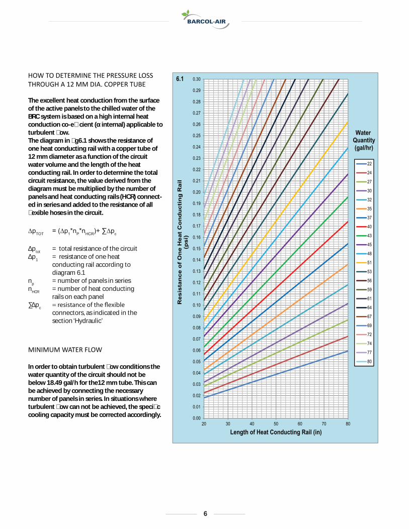
HOW TO DETERMINE THE PRESSURE LOSS THROUGH A 12 MM DIA. COPPER TUBE
The excellent heat conduction from the surface of the active panels to the chilled water of the BRC system is based on a high internal heat conduction co-e�cient (α internal) applicable to turbulent �ow. The diagram in �g6.1 shows the resistance of one heat conducting rail with a copper tube of 12 mm diameter as a function of the circuit water volume and the length of the heat conducting rail. In order to determine the total circuit resistance, the value derived from the diagram must be multiplied by the number of panels and heat conducting rails (HCR) connect-ed in series and added to the resistance of all �exible hoses in the circuit.
MINIMUM WATER FLOW
In order to obtain turbulent �ow conditions the water quantity of the circuit should not be below 18.49 gal/h for the12 mm tube. This can be achieved by connecting the necessary number of panels in series. In situations where turbulent �ow can not be achieved, the speci�c cooling capacity must be corrected accordingly.
∆pTOT = (∆p1*nP*nHCR)+ ∑∆pc
∆ptot = total resistance of the circuit∆p1 = resistance of one heat
conducting rail according to
diagram 6.1np = number of panels in seriesnHCR = number of heat conducting
rails on each panel∑∆pc
connectors, as indicated in the
section ‘Hydraulic’
0.00
0.01
0.02
0.03
0.04
0.05
0.06
0.07
0.08
0.09
0.10
0.11
0.12
0.13
0.14
0.15
0.16
0.17
0.18
0.19
0.20
0.21
0.22
0.23
0.24
0.25
0.26
0.27
0.28
0.29
0.30
20 30 40 50 60 70 80
Res
ista
nce
of
On
e H
eat
Co
nd
uct
ing
Rai
l(p
si)
Length of Heat Conducting Rail (in)
22
24
27
30
32
35
37
40
43
45
48
51
53
56
59
61
64
67
69
72
74
77
80
Water Quantity(gal/hr)
6.1
6

7
7.1
When planning the chilled water distribution it is preferable that the water circulation through the active area is from the window area to the centre of the room. Due to the large tube cross section used on the panels it is possible to connect all panels of one zone in series. This means that only the �rst and the last panel of the zone must be connected to the mains.
The water connections to the mains are in accordance with the room or zone layout. In large rooms or large zones active areas should ideally have the same number of panels in series (equal water distribution). In cases where this is not possible the individual water circuits must be adjusted with appropriate throttling devices, see �g. 7.1
Generally it is recommended that the individual water circuits of the active areas should be isolated from the mains by means
of a ball type valve on the water inlet and outlet branch, see �g. 7.1 (Pos. 3 and 4). The advantages of this method are particularly useful during commissioning work or where alterations have to be made at a later date. During commissioning, the main water installation can be pressure and leak tested with closed ball valves and changes in an active zone can be done without draining the complete system.
The control valves regulate the water quantity in the active zone dependent on the cooling requirements. An inline valve is su�cient for most applications. For further information see under section Controls in this brochure.
For the connection of panels to the mains inlet and outlet as well as the inter connection of the panels in series, �exible all metal bellow type hoses are available, see �g. 7.1 (Pos. 5 and 6). No oxygen can permeate through
the �exible all metal hoses into the chilled water. The �exible hoses are provided with high quality push-on couplings. In order to use the push-on couplings together with the installed armatures a specially designed nipple is available, see Fig. 7.1 (Pos 4).
water volume distribution control valveball-type isolating valve with/without air vent/draining valvenippleflexible connecting hose with push-on couplingsflexible connec-tor with push-on couplings
1
23
45
6
3
2
6
6 6
5
1
HYDRAULIC CIRCUITS

8
7.2
7.
2
3
1
3
2
1
COMPONENTS
bellows type hose with push-on couplings at both ends. No oxygen can permeate through the hose into the chilled water circuit.
TECHNICAL DATA OF THE ALL METAL HOSEstainless steel material code 1.4541 push-on coupling: Legris DN 12 max. operating pressure: 130.53 psi dimensions: DN 10 x 39.37 inches long Cv-value: 46.27 ft3/hr
OF ONE HOSE GIVEN: Cv-value = 46.27 ft3/h, L= 39.27 inch, DN =10, bent 180°, water volume m = 21.13 gal/h
Resistance ∆p ∆p = (m/Cv)2x100 = (21.13/46.27)2 x 100 = 20.85 Pa
Fig. 7.3 shows the push-on coupling which has been specially designed for use with radiant ceilings. The seal is
ring. The coupling hooks on to the copper tube using a segment ring made of stainless spring steel. The advantage of this push-on coupling is found in a very simple, reliable connection and disconnection as well as in the superb production quality.
onto the copper tube end, the unit is lined up with the tube and using light pressure, pushed in the direction of the tube until it has reached the tube stop. When dismantling, the release ring (3) is pushed in the direction of the coupling (disengaging the
Attention: The coupling must only be disconnected after the zone pipe-work has been drained.
metal flexible hose
push on coupling
1
2
double profile ring
made from VITON
segment ring made
of stainless steel
dismantling release
ring
1
2
3

9
7.4
7.5
7.6
Ball type isolating valves, readily available on the market, can be used on the water inlet and outlet branch.
This type of ball valve is recom-mended for installation in the water outlet branch whereby the vent/draining valve should be on the active panel side and not on the main water distribu-tion side. Thus when required the active panels can be depressurized and drained.
which can be tightened and screwed into the ½” NPT thread of the isolating valve using appropriate sealing materials. The stud is machined (12 mm dia.) to receive the push-on coupling of the connecting hose. The nipple can be used on both sides, the water inlet and outlet.
To balance the water quantity of
standard balancing valves with connectors for measuring equipment can be installed.
With regard to control valves, see section Controls.
Barcol-Air brand nipples complete the integrated approach to e�cient installation. The use of one piece, precision-machined brass ensures that the system will be tight and leak free and can be installed with minimum e�ort. The panel and hoses are designed to receive the 12 or 15 mm push-�t coupling of the �exible hoses at one end. Barcol Air can provide various solutions for connection to the piping. Please see Figures 7.4 through 7.6.
Our most popular option is the screw-in nipple, shown in Fig. 7.4.,
1/2” NPT
5/8” OD, ProPress
5/8” ID, soldered

10
8.1
1.2
1.0
0.8
0.6
0.4
0.2
0
62.5 125 250 500 1000 2000 4000 Hz
glass re material 1.56 lb/ft3 1 in thick
stat
ic so
und
abso
rbtio
n fa
ctor
α S
ACOUSTIC
In occupied areas, the sound reverberation factor is reduced to the required level by using sound absorbing materials on the room’s surfaces. A very important area is the ceiling of the room. The useful sound absorbing ceiling area is the perforated part on which the sound absorbing material has been placed.
The diagram, Fig. 8.1, shows the sound absorption factor αS as a function of the frequency for a standard ceiling panel of the following description
• steel panel, material 0.03 inches thick• perforated with 0.1 inches dia holes,16% free area• sound absorbing inlay, glass �ber, material 1 inch thick, weight 1.56 lb/ft3
The main factors in�uencing the sound absorption are:
•the panel material and the type of perforation• the physical properties of the sound absorbing material• the geometry of the ceiling

HOW TO DETERMINE THE PRESSURE LOSS THROUGH A 12 MM DIA. COPPER TUBE
The excellent heat conduction from the surface of the active panels to the chilled water of the BRC system is based on a high internal heat conduction co-e�cient (α internal) applicable to turbulent �ow. The diagram in �g6.1 shows the resistance of one heat conducting rail with a copper tube of 12 mm diameter as a function of the circuit water volume and the length of the heat conducting rail. In order to determine the total circuit resistance, the value derived from the diagram must be multiplied by the number of panels and heat conducting rails (HCR) connect-ed in series and added to the resistance of all �exible hoses in the circuit.
MINIMUM WATER FLOW
In order to obtain turbulent �ow conditions the water quantity of the circuit should not be below 18.49 gal/h for the12 mm tube. This can be achieved by connecting the necessary number of panels in series. In situations where turbulent �ow can not be achieved, the speci�c cooling capacity must be corrected accordingly.
11
1 2 3
35%
50%
40%
30%
25%
20%
0%
10%
20%
30%
40%
50%
1 2 3
Reihe1
Reihe2
9.1
Radiation Convection Humidity
withoutchilledceiling
with chilledceiling
THE PRINCIPLE OF HEAT ABSORPTION
RADIANT CHILLED CEILINGSRadiant chilled ceilings o�er a high degree of thermal comfort with no draughts even in rooms with high heat gains.The radiant heat exchange reduces the degree of convective air move-ments in a room and results in a high level of comfort.
Fig 9.1 shows the metabolic heat transfer of human beings in situations with and without radiant chilled ceilings.
RADIANT HEATRadiant heat is understood to be the energy which is emitted from bodies by means of electromag-netic waves in the range of 0.07 to 2.62*10 ft. For the total emitted radiation in a known speci�ed area and time unit, the equation of Stefan Bolzman is applicable.
E = ε*CS*(T/100)4
E = emitted radiant energy in Btu/ft 2ε = emission ratioCS
of a black cube 0.1714 Btu/(h * ft 2 * °R ) 4
T = absolute temperature in °R
= radiation coefficient-3

12
oitar gnittimeecafrus ε
absolute black cube 1.0bricks, plaster, mortar, gypsum 0.93
49.0)hceeb( rebmit29.0repap78.0)etihw( selit
49.0–29.0enalecrop49.0ssalg19.0erawnehtrae
99.0–49.0etercnoc
aluminium blank finish 0.0418.0–57.0war leets54.0–42.0dehsurb leets
steel zinc coated matt finish 0.08steel zinc coated 0.22–0.28
70.0thgirb reppoccopper black oxidated 0.78
50.0dehsilop ssarb24.0dehsinrub ssarb
aluminium bronze paint 0.20–0.4039.0tniap rotaidar39.0tniap dael der
79.0–88.0tniap lio
powder coating of ceiling panels 0.90–0.95
9.2 9.4
Solid materials absorb the non re�ective radiation so intensively, that no radiation can penetrate through the layers of even a few hundredths of a millimeter in thickness. In these circumstances one speaks of the ra-diation of technical surfaces. The table 9.2 shows the emission ratio of di�erent surfaces.
Fig. 9.3 shows the e�ect of heat ra-diation at di�erent angles. Aparticu-lar surface element absorbs radiantenergy from all directions. The ab-sorbed radiant energy is not a�ectedup to an angle of 50°. At an angle of75° the absorbed radiant energy isstill 78% compared with the value ata right angle to the surface. The mostimportant advantage of the BRCradiant chilled ceiling results fromthis observation - namely - the largearea e�ectively covered.
13
9.3
% 001
% 08
% 06
0°20° 20°
40° 40°
60° 60°
80° 80°
90° 90°
70° 70°
50° 50°
30° 30°
10° 10°
% 04
% 02
% 0
% 02
% 04
% 06
% 08
% 001
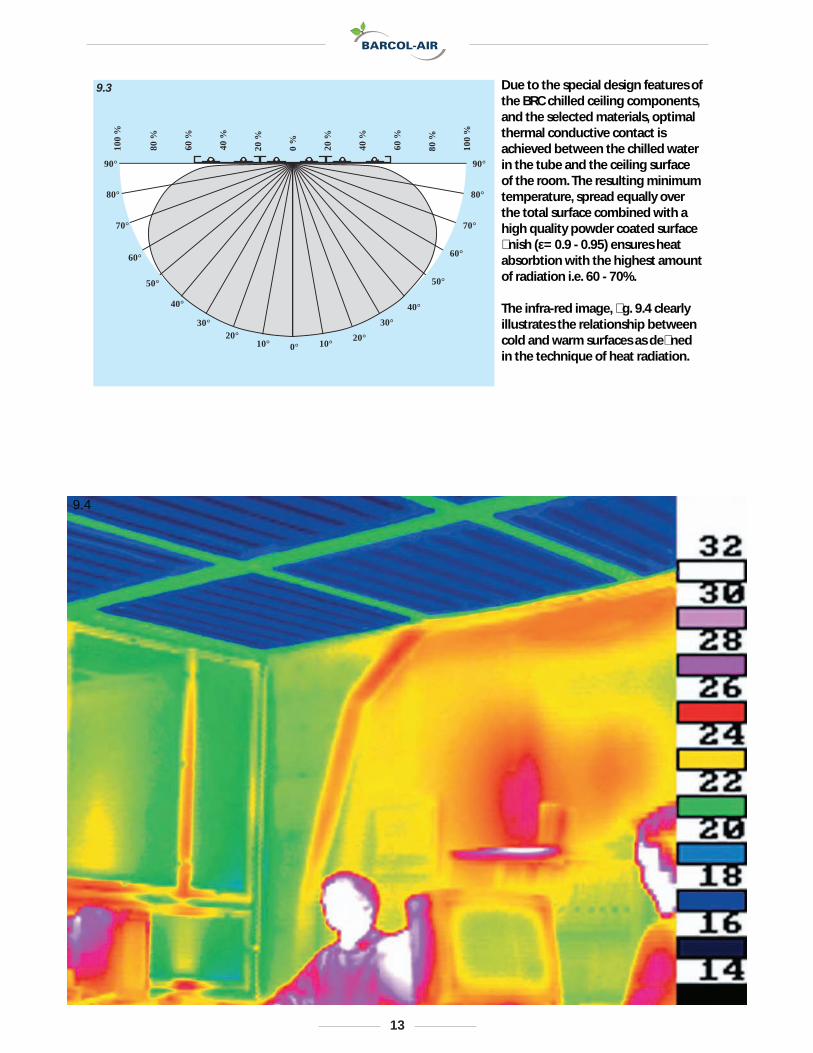
Due to the special design features of the BRC chilled ceiling components, and the selected materials, optimal thermal conductive contact is achieved between the chilled water in the tube and the ceiling surface of the room. The resulting minimum temperature, spread equally over the total surface combined with a high quality powder coated surface �nish (ε= 0.9 - 0.95) ensures heat absorbtion with the highest amount of radiation i.e. 60 - 70%.
The infra-red image, �g. 9.4 clearly illustrates the relationship between cold and warm surfaces as de�ned in the technique of heat radiation.
9.4

14
t
B2
Y1
N
Y2
Y2
Y1
- +
100 %
0 %
B1
data line to the following room
data line from previous rooms
room air temperature
heating cooling
valve shut whensaturation pointis reached
N zone controllerB1 room temperature sensorB2 dewpoint sensorY1 chilled water valveY2 heating valve
10.1
CONTROL OF CHILLED CEILINGS
Where variable internal and external heat loads prevail, the cooling output of a chilled ceiling is varied with the aid of a simple room controller. Normal control is achieved by throttling the water
content and the optimal selection of the material used on BRC chilled ceilings ensure a fast reaction to any changes in heat load. The resulting control characteristics are comparable with those achieved with air systems. Normally the algorithm PI-reaction is selected with a proportional band of 1.8 °R and a re-adjustment time of 10 minutes. Using such control, large heat load changes can be corrected quickly with stable results. An unintentional drift of the room air temperature, which would
not therefore occur.
In order to achieve a stable control circuit, the correct sizing of the control valve is important. It is recomended that the valve
authority is between 0.5 and 1. This means that the pressure drop, when the valve position is fully open, is equivalent to factor 0.5 - 1 of the pressure drop calculated for the zone circuit. To avoid sedimentation it is recom-mended not to install valves with Cv values smaller than 35 ft3/h. In zones where more than one control valve is installed, care should be taken that all valves operate in parallel.
To avoid condensation, the chilled water temperature must always remain above the dew point of the room air. This must be achieved by the consequent
temperature.
To eliminate any possibility of condensation, it is recomended to install a dew point sensor into each zone as a safety precaution. Prior to reaching critical satura-tion, the sensor would react and as a resultthe control valve would prohibit
any water circulation in the zone.
As an option, a perimeter heating system as well as a fresh air supply system could be operated in sequence (zero energy band 1.8 °R) with the chilled ceiling.
Since one of the characteristics of the BRC chilled ceiling system is the large area coverage (as explained in the chapter Heat Radiation, page11) it is recom-mended to allow in open plan
zones between 750 and 1400 ft2 can be planned.
Fig. 10.1 shows a schematic layout of standard equipment used on a control zone.

15
11.1
horizontal section illustration of sections
temperature [ oC]vertical section
tem
pera
ture
[ o C
] Intersection Picture
Browser
help
end
COMMISSIONING
PRESSURE TESTINGLike all hydraulic systems used inbuildings, the chilled ceiling systemsmust be tested for possible leaks andtested to withstand the working pres-sure. These tests must be done priorto commissioning, observing thelocal rules and regulations.
OPERATIONAL TESTINGTo achieve correct operation of thechilled ceiling, the system must becarefully vented. Furthermore, proofof water �ow through all pipe workincluding the panel tubes is essential.The use of modern infra-red camerasystems with image recording capa-city provides a professional solution.The infra-red image print-out shouldBe part of the commissioning manual.Fig 11.1 shows a typical thermalimage including computerized eva-luation of an active zone in operation.

16
COMPLETED INSTALLATIONS
BRC chilled ceilings in modern conference rooms

17
BRC chilled ceilings and rectangular panels

18
Space cooling with Barcol-Air radiant ceilings

19
Barcol-Air radiant ceilings in conference rooms, with integrated
rimless air diffuser in the panels
Barcol-Air radiant ceiling technology, cassettes and circular segment panels

20
Barcol-Air radiant ceilings in offices

21
Barcol-Air conical banister panels
BRC chilled ceilings in cassette form

Contacts
Headquarters
Barcol-Air Ltd.115 Hurley RoadOxford, CT 06478Phone: 203-262-9900Fax: 203-262-9906Email: [email protected]: www.barcolairusa.com
Barcol-Air Ltd.Georgetown Center, Building B5963 Coreson Avenue SouthSeattle, WA 98108
Website: www.barcolairusa.com
Your partner for radiant cooling and heating,chilled beams and VAV systems.


