38
BARR ENVIRONMENTAL LTD Killoch Energy Recovery Park Heat and Power Plan May 2015
| Date post: | 16-Mar-2018 |
| Category: |
Documents |
| Upload: | vuongnguyet |
| View: | 224 times |
| Download: | 7 times |

BARR ENVIRONMENTAL LTD
Killoch Energy Recovery Park
Heat and Power Plan
May 2015
Wardell Armstrong Suite 2/3, Great Michael House, 14 Links Place, Edinburgh, EH6 7EZ, United Kingdom Telephone: +44 (0)131 555 3311 Facsimile: +44 (0)131 553 3284 www.wardell-armstrong.com
Wardell Armstrong is the trading name of Wardell Armstrong LLP, Registered in England No. OC307138.
Registered office: Sir Henry Doulton House, Forge Lane, Etruria, Stoke-on-Trent, ST1 5BD, United Kingdom
UK Offices: Stoke-on-Trent, Birmingham, Cardiff, Carlisle, Edinburgh, Greater Manchester, London, Newcastle upon Tyne, Penryn, Sheffield, Truro, West Bromwich. International Offices: Almaty, Moscow
ENERGY AND CLIMATE CHANGE
ENVIRONMENT AND SUSTAINABILITY
INFRASTRUCTURE AND UTILITIES
LAND AND PROPERTY
MINING AND MINERAL PROCESSING
MINERAL ESTATES AND QUARRYING
WASTE RESOURCE MANAGEMENT
DATE ISSUED: May 2015
JOB NUMBER: LE12479
REPORT NUMBER: 010
BARR ENVIRONMENTAL LTD
Killoch Energy Recovery Park
Heat and Power Plan
PREPARED BY:
John Topping Technical Director APPROVED BY:
John Topping Technical Director
This report has been prepared by Wardell Armstrong LLP with all reasonable skill, care and diligence, within the terms of the Contract with the Client. The report is confidential to the Client and Wardell Armstrong LLP accept no responsibility of whatever nature to third
parties to whom this report may be made known.
No part of this document may be reproduced without the prior written approval of Wardell Armstrong LLP.
BARR ENVIRONMENTAL LTD Killoch Energy Recovery Park
LE12479/010 May 2015
CONTENTS
1 Description of Facility Technologies 1
1.1 Introduction 1
1.2 Description of Technologies for Thermal Conversion of Waste 1
1.3 Electricity Grid Connections 5
1.4 Heat Connection and Distribution 5
2 Description of Waste to be Treated and its Energy Value 7
2.1 Details of Waste Input 7
2.2 Calorific Values of Waste to be Treated 8
2.3 Energy Generation 9
2.4 Facility Efficiency 9
2.5 Quality Index 10
2.6 Seasonal Variation in Heat Demand 14
2.7 Assumptions 14
2.8 Support Mechanisms 14
2.9 Heat Map 18
3 Heat and Power Plan 19
3.1 Potential Applications for Secondary Heat 19
3.2 Potential Individual Heat Users 20
3.3 Appraisal of Individual Heat Users 20
3.4 Potential Heat Demand and Assumptions 23
3.5 Next Actions 24
3.6 Distribution Networks 24
3.7 QI and Overall Efficiency for each year of Heat Plan 25
3.8 Implementation Timetable 25
3.9 Outcome of Discussions with Local Planners 26
APPENDICES
Appendix 1 Energy Balance and Installation Boundaries
Appendix 2 Registration of Application for Scottish Power Energy Networks Connection
DRAWINGS
LE12479-012 Potential Cable Route
LE12479-013 Location of Potential Heat Offtakers
BARR ENVIRONMENTAL LTD Killoch Energy Recovery Park
LE12479-010 May 2015
Page 1
1 DESCRIPTION OF FACILITY TECHNOLOGIES
1.1 Introduction
1.1.1 This Heat and Power Plan submission has been prepared on behalf of Barr
Environmental Ltd (BEL) for the Killoch Energy Recovery Park (ERP) to be located at
its existing head office and training centre site at Killoch.
1.1.2 The Plan has been produced following SEPA guidelines to demonstrate how the
proposed facility will utilise energy from the thermal treatment of waste in an
efficient manner.
1.2 Description of Technologies for Thermal Conversion of Waste
1.2.1 Barr Environmental Ltd (BEL) plans to install an energy recovery facility at its Killoch
site in East Ayrshire to provide treatment and recovery services for unsorted
municipal wastes and commercial and industrial wastes of a similar nature to
municipal residual waste. The facility will utilise mechanical treatment and advanced
thermal treatment (ATT) gasification technologies to recover recyclable materials,
where practicable, and generate heat and power from the remaining residual
wastes. The mechanical treatment facility will handle circa 120,000 tonnes per
annum (tpa) of residual wastes predominantly from municipal sources. The ATT
facility will process circa 85,000 tpa.
Materials Recovery Facility
1.2.2 The Materials Recovery Facility (MRF) will utilise robust mechanical treatment
technologies to recover a range of recyclable materials from the incoming wastes
and prepare the residual waste as a refuse derived fuel (RDF) for treatment in the
ATT Facility. The waste sources will predominantly be of municipal origin and so the
plant will target the recovery of non-ferrous metals and dense plastics as required
under the Waste (Scotland) Regulations 2012. The proposals for the Killoch facility
also include the recovery of ferrous metals and paper/card and therefore go beyond
the minimum requirements set out in the Regulations.
1.2.3 Recovered recyclable materials will be exported off-site to appropriate re-processing
facilities and the remaining residual material will be used as a RDF for energy
recovery within the ATT Facility.
BARR ENVIRONMENTAL LTD Killoch Energy Recovery Park
LE12479-010 May 2015
Page 2
ATT Facility
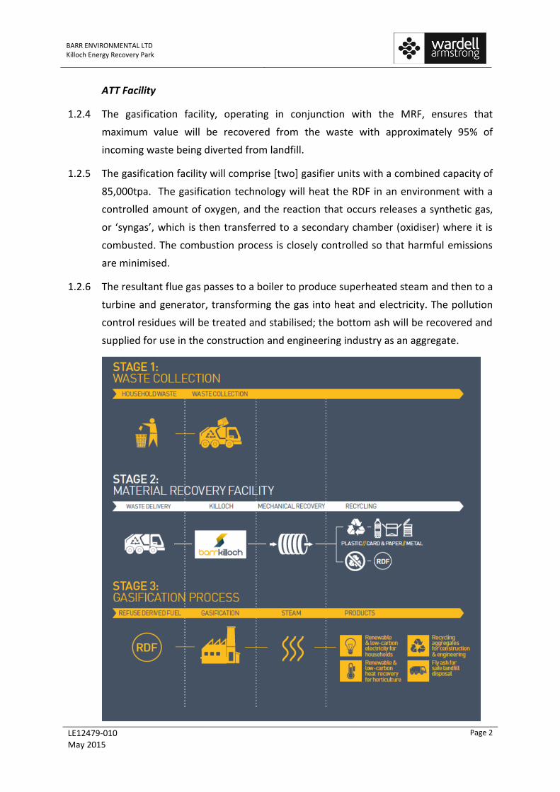
1.2.4 The gasification facility, operating in conjunction with the MRF, ensures that
maximum value will be recovered from the waste with approximately 95% of
incoming waste being diverted from landfill.
1.2.5 The gasification facility will comprise [two] gasifier units with a combined capacity of
85,000tpa. The gasification technology will heat the RDF in an environment with a
controlled amount of oxygen, and the reaction that occurs releases a synthetic gas,
or ‘syngas’, which is then transferred to a secondary chamber (oxidiser) where it is
combusted. The combustion process is closely controlled so that harmful emissions
are minimised.
1.2.6 The resultant flue gas passes to a boiler to produce superheated steam and then to a
turbine and generator, transforming the gas into heat and electricity. The pollution
control residues will be treated and stabilised; the bottom ash will be recovered and
supplied for use in the construction and engineering industry as an aggregate.
BARR ENVIRONMENTAL LTD Killoch Energy Recovery Park
LE12479-010 May 2015
Page 3
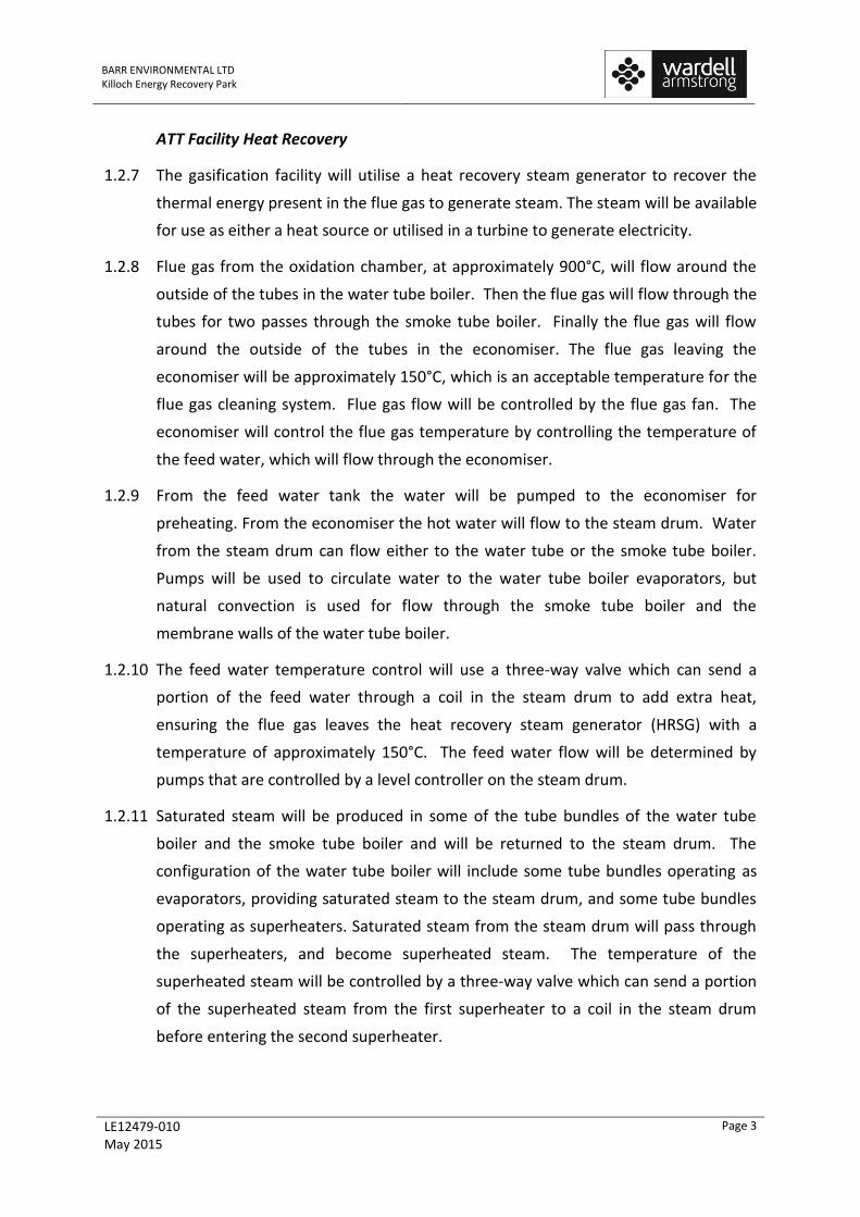
ATT Facility Heat Recovery
1.2.7 The gasification facility will utilise a heat recovery steam generator to recover the
thermal energy present in the flue gas to generate steam. The steam will be available
for use as either a heat source or utilised in a turbine to generate electricity.
1.2.8 Flue gas from the oxidation chamber, at approximately 900°C, will flow around the
outside of the tubes in the water tube boiler. Then the flue gas will flow through the
tubes for two passes through the smoke tube boiler. Finally the flue gas will flow
around the outside of the tubes in the economiser. The flue gas leaving the
economiser will be approximately 150°C, which is an acceptable temperature for the
flue gas cleaning system. Flue gas flow will be controlled by the flue gas fan. The
economiser will control the flue gas temperature by controlling the temperature of
the feed water, which will flow through the economiser.
1.2.9 From the feed water tank the water will be pumped to the economiser for
preheating. From the economiser the hot water will flow to the steam drum. Water
from the steam drum can flow either to the water tube or the smoke tube boiler.
Pumps will be used to circulate water to the water tube boiler evaporators, but
natural convection is used for flow through the smoke tube boiler and the
membrane walls of the water tube boiler.
1.2.10 The feed water temperature control will use a three-way valve which can send a
portion of the feed water through a coil in the steam drum to add extra heat,
ensuring the flue gas leaves the heat recovery steam generator (HRSG) with a
temperature of approximately 150°C. The feed water flow will be determined by
pumps that are controlled by a level controller on the steam drum.
1.2.11 Saturated steam will be produced in some of the tube bundles of the water tube
boiler and the smoke tube boiler and will be returned to the steam drum. The
configuration of the water tube boiler will include some tube bundles operating as
evaporators, providing saturated steam to the steam drum, and some tube bundles
operating as superheaters. Saturated steam from the steam drum will pass through
the superheaters, and become superheated steam. The temperature of the
superheated steam will be controlled by a three-way valve which can send a portion
of the superheated steam from the first superheater to a coil in the steam drum
before entering the second superheater.
BARR ENVIRONMENTAL LTD Killoch Energy Recovery Park
LE12479-010 May 2015
Page 4
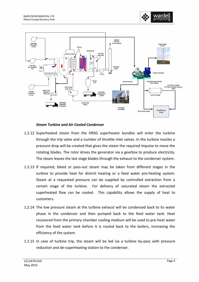
Steam Turbine and Air Cooled Condenser
1.2.12 Superheated steam from the HRSG superheater bundles will enter the turbine
through the trip valve and a number of throttle inlet valves. In the turbine nozzles a
pressure drop will be created that gives the steam the required impulse to move the
rotating blades. The rotor drives the generator via a gearbox to produce electricity.
The steam leaves the last stage blades through the exhaust to the condenser system.
1.2.13 If required, bleed or pass-out steam may be taken from different stages in the
turbine to provide heat for district heating or a feed water pre-heating system.
Steam at a requested pressure can be supplied by controlled extraction from a
certain stage of the turbine. For delivery of saturated steam the extracted
superheated flow can be cooled. This capability allows the supply of heat to
customers.
1.2.14 The low pressure steam at the turbine exhaust will be condensed back to its water
phase in the condenser and then pumped back to the feed water tank. Heat
recovered from the primary chamber cooling medium will be used to pre-heat water
from the feed water tank before it is routed back to the boilers, increasing the
efficiency of the system.
1.2.15 In case of turbine trip, the steam will be led via a turbine by-pass with pressure
reduction and de-superheating station to the condenser.

BARR ENVIRONMENTAL LTD Killoch Energy Recovery Park
LE12479-010 May 2015
Page 5
1.2.16 Bleed or pass-out steam may be taken from different stages in the turbine to obtain
required temperature for a drying, district heating or feed water pre-heating system,
as required. Steam at a requested pressure can be supplied by controlled extraction
from different stages of the turbine. For delivery of saturated steam the extracted
flow would be de-superheated. For supply of hot water off site a heat exchanger
would be required, along with other infrastructure.
1.3 Electricity Grid Connections
1.3.1 Following discussions with Scottish Power Energy Networks (SPEN), the Distribution
Network Operator (DNO), and detailed assessment of the local distribution
infrastructure, an electricity grid connection is to be agreed with SPEN for
connection to the distribution network. This connection will be made to the
distribution network through a connection to the substation immediately to the
northeast of the Killoch site. The indicative cable route to be agreed with SPEN is
shown on Drawing Number LE12479-012.
1.3.2 The connection application to SPEN has now been registered and confirmation of
this is provided as Appendix 2.
1.4 Heat Connection and Distribution
1.4.1 Options for use of heat from the Facility are detailed in Section 3 of this Heat and
Power Plan. Given the types of applications and properties likely to be able to accept
heat from the Facility, it is anticipated that heat will be supplied in the form of hot
water at between 40°C and 90°C depending on the application and will be delivered
through a buried pipe network. Heat will be distributed to the customer via a
network of insulated pipes.
1.4.2 Generally heat will be supplied to a secondary heat exchanger at the point of use;
however, in some applications hot water may be utilised directly to avoid a further
temperature drop. If the application requires further upgrading of heat then
typically, the heat exchanger at the end user is arranged to supply heat to a tertiary
heating circuit with a boiler plant.
1.4.3 The turbine at the Killoch site will be enabled for the extraction of steam. This would
most likely feed into a heat exchanger as the export of hot water for low
temperature process heating, district heating and/or cooling uses is considered to be
the most practicable use of heat in the area surrounding the site. The existing site
layout also provides for the future installation of the necessary heat exchangers,

BARR ENVIRONMENTAL LTD Killoch Energy Recovery Park
LE12479-010 May 2015
Page 6
water treatment and distribution infrastructure by the developer of the district
heating networks as these are installed.
1.4.4 Routing of the distribution pipe work leaving the site will be finalised once an
agreement has been reached with a potential heat user. Discussions with potential
heat end users have identified a number of potential heat distribution options and
heat uses on the Killoch site; these are discussed in more detail in Section 3.
BARR ENVIRONMENTAL LTD Killoch Energy Recovery Park
LE12479-010 May 2015
Page 7
2 DESCRIPTION OF WASTE TO BE TREATED AND ITS ENERGY VALUE
2.1 Details of Waste Input
2.1.1 The Killoch Energy Recovery Park (ERP) will treat up to 120,000 tpa of waste of which
up to 85,000 tpa of waste will be processed through the ATT element of the facility.
The input wastes will comprise unsorted municipal wastes and commercial and
industrial residual wastes suitable for thermal treatment. It is intended that the
input waste will be predominantly sourced from East and South Ayrshire, where
there is currently a shortage of suitable treatment outlets to avoid the landfilling
and/or exporting of the valuable energy resource.
2.1.2 It is anticipated that the input waste will contain variable quantities of the following
materials:
Paper and card including recyclable paper, card and card packaging and non-
recyclable paper;
Plastic film and dense plastic containers;
Textiles;
Glass;
Organic wastes, including kitchen and garden waste and other putrescibles;
Ferrous metals;
Non-ferrous metals;
Miscellaneous combustibles;
Miscellaneous non-combustibles; and
Fines.
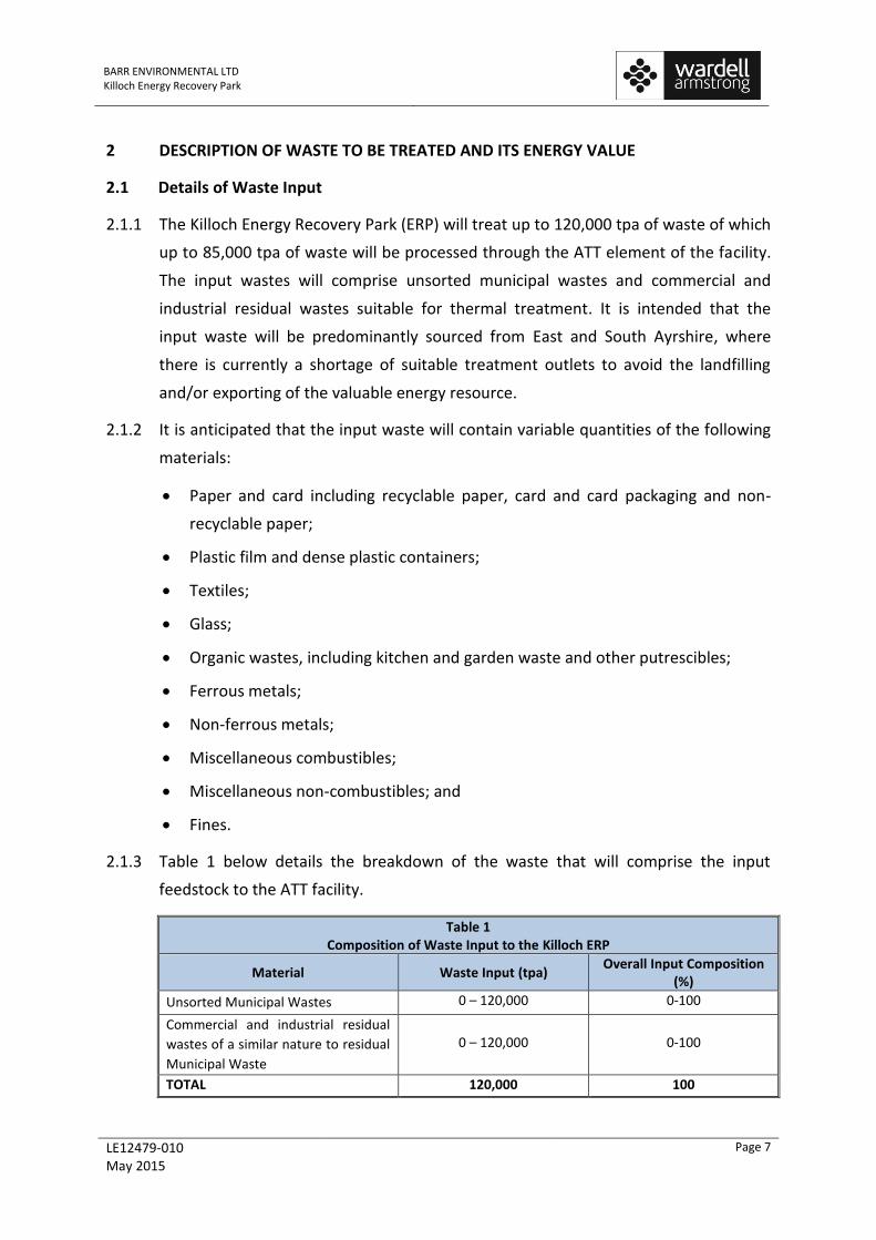
2.1.3 Table 1 below details the breakdown of the waste that will comprise the input
feedstock to the ATT facility.
Table 1 Composition of Waste Input to the Killoch ERP
Material Waste Input (tpa) Overall Input Composition
(%)
Unsorted Municipal Wastes 0 – 120,000 0-100
Commercial and industrial residual
wastes of a similar nature to residual
Municipal Waste
0 – 120,000 0-100
TOTAL 120,000 100

BARR ENVIRONMENTAL LTD Killoch Energy Recovery Park
LE12479-010 May 2015
Page 8
2.1.4 The Materials Recovery Facility (MRF) will recover ferrous metals, paper/card, non-
ferrous metal and hard plastics for recycling, and create a refuse derived fuel for
input to the ATT facility. This processing is designed to exceed the requirements of
the Waste (Scotland) Regulations 2012 and SEPA’s Thermal Treatment of Waste
Guidelines with respect to the treatment of unsorted wastes from municipal sources.
2.1.5 The MRF will also process commercial and industrial wastes of a similar nature to
residual municipal wastes. As it is acknowledged in SEPA’s guidance1 that there is
likely to be limited requirement for pre-processing of residual wastes from
commercial and industrial sources prior to thermal treatment, the proposals for the
Killoch facility go beyond the minimum requirements set out in the guidance.
2.1.6 The remaining residual waste will be comprised primarily of:
miscellaneous combustibles – GCV as fired circa 13MJ/kg; and
residual non-combustibles – GCV as fired circa 2.5MJ/kg
non-recyclable paper and card – GCV as fired circa 11MJ/kg;
plastic films – GCV as fired circa 19MJ/kg;
non-recyclable dense plastics – GCV as fired circa 28MJ/kg;
wood – GCV as fired circa 16MJ/kg; and
organics – GCV as fired circa 4MJ/kg.
2.2 Calorific Values of Waste to be Treated
2.2.1 Table 2 below details the fuel materials that will comprise the input feedstock to the
ATT facility. This refuse derived fuel (RDF) is made up of residual material from the
RDF plant.
Table 2
Fuel inputs for the Facility
Type of Waste Amount Amount NCV GCV Energy
tonnes/yr % (MJ/kg) (MJ/kg) (GJ gross)
RDF Materials 85,000 100% 12.0 13.2 1,122,000
TOTAL 85,000 100% 12.0 13.2 1,122,000
1 SEPA, 2014. Thermal Treatment of Waste Guidelines

BARR ENVIRONMENTAL LTD Killoch Energy Recovery Park
LE12479-010 May 2015
Page 9
2.3 Energy Generation
2.3.1 The energy generation calculations have been based on the assumption that the ATT
element of the facility will operate for 7,800 hours per year. These operational hours
take account of periods of plant downtime. Seasonal variations in feedstock are not
expected to be significant and these are reflected in the average RDF calorific value.
2.3.2 Table 3 details the anticipated energy generation from the Killoch ERP and indicates
the potential heat available for export and the Total Power Output (CHPTPO) defined
by the CHPQA scheme guidance. The table also sets out the net power output
(CHPQPO) from the Killoch ERP, which is used to calculate the electrical efficiency of
the ATT facility under the SEPA Thermal Treatment of Waste Guidelines.
Table 3
Summary Table of Energy Production and Expenditure
Parameter Energy (MWh)
Annual Energy
(GJ)
Equivalent Capacity
(MW)
Percentage of Input Energy
Operating hours per year 7,800
Energy from waste (85,000tpa) 311,667 1,122,000 39.96 99.62%
Support fuel for start up pa) 1,100 3,960 0.14 0.35%
Imported electrical power 100 360 0.01 0.03%
Total inputs 312,867 1,126,320 40.11 100.00%
Energy losses during thermal treatment process
237,207 853,944 30.41 75.82%
Qualifying Power Export (CHPQPO) 63,960 230,256 8.20 20.44%
Parasitic load (electricity) 11,700 42,120 1.50 3.74%
Useful Heat (CHPQHO) 0 0 0.00 0.00%
Total outputs 312,867 1,126,320 40.11 100.00%
Total Power Output (CHPTPO) 75,660 272,376 9.70 24.18%
2.4 Facility Efficiency
2.4.1 As set out in Table 3, the efficiency of the ATT Facility is 24.18% for electrical
generation based on gross power output (CHPTPO) and 20.44% based on net power
output (CHPQPO); with no heat export assumed on day one, this gives an overall
efficiency of 20.44% at commencement of operation based on gross CV energy input
and net power output.
BARR ENVIRONMENTAL LTD Killoch Energy Recovery Park
LE12479-010 May 2015
Page 10
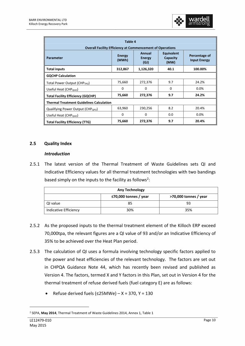
Table 4
Overall Facility Efficiency at Commencement of Operations
Parameter Energy (MWh)
Annual Energy
(GJ)
Equivalent Capacity
(MW)
Percentage of Input Energy
Total inputs 312,867 1,126,320 40.1 100.00%
GQCHP Calculation
Total Power Output (CHPTPO) 75,660 272,376 9.7 24.2%
Useful Heat (CHPQHO) 0 0 0 0.0%
Total Facility Efficiency (GQCHP) 75,660 272,376 9.7 24.2%
Thermal Treatment Guidelines Calculation
Qualifying Power Output (CHPQPO) 63,960 230,256 8.2 20.4%
Useful Heat (CHPQHO) 0 0 0.0 0.0%
Total Facility Efficiency (TTG) 75,660 272,376 9.7 20.4%
2.5 Quality Index
Introduction
2.5.1 The latest version of the Thermal Treatment of Waste Guidelines sets QI and
Indicative Efficiency values for all thermal treatment technologies with two bandings
based simply on the inputs to the facility as follows2:
2.5.2 As the proposed inputs to the thermal treatment element of the Killoch ERP exceed
70,000tpa, the relevant figures are a QI value of 93 and/or an Indicative Efficiency of
35% to be achieved over the Heat Plan period.
2.5.3 The calculation of QI uses a formula involving technology specific factors applied to
the power and heat efficiencies of the relevant technology. The factors are set out
in CHPQA Guidance Note 44, which has recently been revised and published as
Version 4. The factors, termed X and Y factors in this Plan, set out in Version 4 for the
thermal treatment of refuse derived fuels (fuel category E) are as follows:
Refuse derived fuels (≤25MWe) – X = 370, Y = 130
2 SEPA, May 2014, Thermal Treatment of Waste Guidelines 2014, Annex 1, Table 1
Any Technology
≤70,000 tonnes / year >70,000 tonnes / year
QI value 85 93
Indicative Efficiency 30% 35%
BARR ENVIRONMENTAL LTD Killoch Energy Recovery Park
LE12479-010 May 2015
Page 11
2.5.4 The revised version of the SEPA’s Thermal Treatment of Waste Guidelines 2014
state, “With respect to the standards to be applied, SEPA will, unless specified
differently elsewhere in these guidelines, have regard to the Quality Assurance for
Combined Heat and Power (CHPQA) standard, as an appropriate approach to
establishing the required energy efficiency for facilities. For clarity and unless
specified differently elsewhere in these guidelines, in having regard to the CHPQA
standard, SEPA will use as far as possible the terminology, definitions of, and
methods used in that standard.”
2.5.5 On this basis, it is considered that the QI formulae and fuel categories as set out in
the current CHPQA Guidance Note 44, Version 4 should be used for this facility and
these have been used in this Plan.
Quality Index
2.5.6 Heat and Power Plan targets for energy from waste technologies with a capacity of
>70,000 tonnes per annum should achieve a CHP Quality Index (QI) value of 93 with
an indicative overall plant efficiency of 35% over the Heat Plan period. The QI value
is calculated as follows:
QI value = (X) x ηpower + (Y) x ηheat
Where
X = 370 and Y = 130 for solid waste CHP plants ≤25MWe
ηpower = electrical efficiency (%)
ηheat = heat efficiency (%)
2.5.7 The net electrical efficiency of the ACF has been calculated as 20.44% (see Table 4)
generating circa 64,000 MWh of electricity per annum. This is based on an net
capacity of 8.2 MWe and a guaranteed availability of 7,800 operating hours pa with
the output measured at the export meter in accordance with SEPA guidance. The
heat efficiency on day one is currently assessed as 0% based on no heat export from
the facility. However, Barr Environmental Ltd is currently investigating the potential
for heat use within the other buildings located at the Killoch site. There is the
possibility that this heat offtake can be implemented as part of the construction of
the Killoch ERP and contribute to the overall efficiency of the Killoch ERP on day one.
The progress of this and other heat offtakes will continue to be reviewed and
reported in updates to this Heat Plan.
BARR ENVIRONMENTAL LTD Killoch Energy Recovery Park
LE12479-010 May 2015
Page 12
2.5.8 The calculations of efficiency are based on a similar turbine technology to that used
at other facilities built by the proposed technology supplier and are therefore
representative of typical electrical efficiencies. However, the technology supplier
has continued to refine their boiler design and work with their turbine
manufacturers to increase the efficiency of electrical generation, based on
operational data at their existing reference plants located across Europe.
2.5.9 In addition, they continue to identify additional heat recovery measures which will
be implemented at the Killoch facility. This ongoing review will continue through the
detailed design of the plant and the technology supplier will be required to
demonstrate that the plant efficiency has been optimised during the detailed design
review process and during commissioning .
Facility Quality Index
2.5.10 The Thermal Treatment Guidelines use the methodology set out in the CHPQA
guidance to calculate the Quality Index for the chosen technology and provide
benchmarks for different technologies which set minimum standards to be achieved
in the planning and permitting context.
2.5.11 The benchmark QI figure is defined as 93 for all technologies with a capacity of
>70,000tpa.
2.5.12 The QI of the facility based on the CHPQA factors for the thermal treatment of RDF,
the overall net electrical and heat efficiencies set out in Table 4 and assuming no
heat export from the ATT Facility on day one is thus:
QI value = 370 x 20.44% + 130 x 0% = 75.6 compared with a benchmark figure of
93
2.5.13 The benchmark efficiency figure is now defined in the Guidelines as 35% for all
technologies >70,000tpa. The calculated efficiency at the commencement of
operations is calculated as 20.44% as set out in section 2.4.
2.5.14 The figures are based on the calculations of fuel inputs and guaranteed electrical
outputs and parasitic loads from the technology supplier. As these figures will
undoubtedly change once the Killoch ERP is operational and actually receiving and
treating waste, the figures of 75.6 and 20.44% should be recalculated from first
principles, as set out above, once the plant is operational and the actual energy
inputs and outputs can be determined from metered figures.
BARR ENVIRONMENTAL LTD Killoch Energy Recovery Park
LE12479-010 May 2015
Page 13
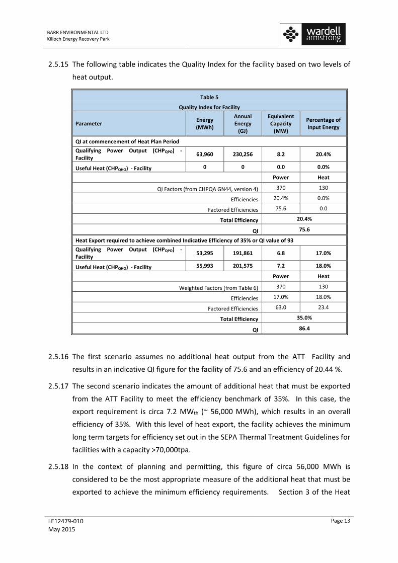
2.5.15 The following table indicates the Quality Index for the facility based on two levels of
heat output.
Table 5
Quality Index for Facility
Parameter Energy (MWh)
Annual Energy
(GJ)
Equivalent Capacity
(MW)
Percentage of Input Energy
QI at commencement of Heat Plan Period
Qualifying Power Output (CHPQPO) - Facility
63,960 230,256 8.2 20.4%
Useful Heat (CHPQHO) - Facility 0 0 0.0 0.0%
Power Heat
QI Factors (from CHPQA GN44, version 4) 370 130
Efficiencies 20.4% 0.0%
Factored Efficiencies 75.6 0.0
Total Efficiency 20.4%
QI 75.6
Heat Export required to achieve combined Indicative Efficiency of 35% or QI value of 93
Qualifying Power Output (CHPQPO) - Facility
53,295 191,861 6.8 17.0%
Useful Heat (CHPQHO) - Facility 55,993 201,575 7.2 18.0%
Power Heat
Weighted Factors (from Table 6) 370 130
Efficiencies 17.0% 18.0%
Factored Efficiencies 63.0 23.4
Total Efficiency 35.0%
QI 86.4
2.5.16 The first scenario assumes no additional heat output from the ATT Facility and
results in an indicative QI figure for the facility of 75.6 and an efficiency of 20.44 %.
2.5.17 The second scenario indicates the amount of additional heat that must be exported
from the ATT Facility to meet the efficiency benchmark of 35%. In this case, the
export requirement is circa 7.2 MWth (~ 56,000 MWh), which results in an overall
efficiency of 35%. With this level of heat export, the facility achieves the minimum
long term targets for efficiency set out in the SEPA Thermal Treatment Guidelines for
facilities with a capacity >70,000tpa.
2.5.18 In the context of planning and permitting, this figure of circa 56,000 MWh is
considered to be the most appropriate measure of the additional heat that must be
exported to achieve the minimum efficiency requirements. Section 3 of the Heat
BARR ENVIRONMENTAL LTD Killoch Energy Recovery Park
LE12479-010 May 2015
Page 14
and Power Plan identifies the heat offtakers in the vicinity of the site to achieve the
overall efficiency requirements over the Plan period.
2.6 Seasonal Variation in Heat Demand
2.6.1 Details of the seasonal variation of heat demands on the ATT facility are discussed in
Section 3.
2.7 Assumptions
The ATT facility operates 7,800 hours per year;
The ATT facility operates at full capacity, i.e. 85,000 tpa, which is a conservative
assumption with respect to the overall facility efficiency. The actual throughput
will vary dependent on the quantity of recyclate available for recovery from the
municipal wastes and commercial wastes;
The GCV of the input material will be variable based on the wide range of
compositions that can arise in unsorted municipal wastes and across different
commercial sectors. The GCV of the RDF will be reduced by the extraction of
plastic but the GCV as fired will be improved by the removal of metals from the
input materials;
The power output from the ATT facility will be metered at the point of export
from the site;
The steam turbine of the ATT facility will be enabled for the export of steam at
low pressure to feed a district heating network or other heat offtaker via a heat
exchanger;
The Killoch facility layout has sufficient space available for the future installation
of the necessary infrastructure to export heat to a district heating network.
2.8 Support Mechanisms
Renewables Obligation
2.8.1 Introduced in 2002 the Renewables Obligation (Scotland) (ROS) requires all
electricity suppliers to supply a set proportion of their electricity from eligible
renewable sources. The current requirement is set at 29% for 2015-2016. In 2009 the
ROS was amended to include a system of banding whereby different technologies
receive different levels of support. Gasification of biomass, including biomass from
waste, was given a higher level of support following this review.

BARR ENVIRONMENTAL LTD Killoch Energy Recovery Park
LE12479-010 May 2015
Page 15
2.8.2 For the purposes of the ROS, renewable sources of biomass include everything that
is not derived from fossil fuel. The waste inputs will have been processed and sorted
by the RDF plant to remove various recyclable materials and non-combustible
materials prior to treatment in the ACF facility. This process will tend to increase the
biomass content of the RDF through removal of metals and inert materials. It is
estimated that the remaining biomass element in the fuel stream after sorting will
be over 50% by calorific value. However, analysis of the waste inputs will be
required once the plant is operational in order to define the level of SROC’s eligibility
for the Total Power Output of the plant.
2.8.3 Under the ROS tradable certificates called Renewables Obligation Certificates
(SROCs) were previously issued to generators in proportion to the amount of
renewable electricity generated. Advanced gasification, where the syngas produced
has a CV of 4 MJ/m3 or greater received 2SROCs per MWh of eligible electricity
generated whereas standard gasification, where the syngas produced has a CV of
greater than 2 MJ/m3 but less than 4 MJ/m3 received 1 SROC per MWh.
2.8.4 Recent changes to the ROS mean that all gasification plants, regardless of whether
they would have been regarded as standard or advanced under the previous regime,
will attract support at 1.9 ROCs per MWh. This will degress over the period to the
next banding review (when it is intended that the scheme will close):
1.9 ROCs/MWh in 2015/2016;
1.8 ROCs/MWh in 2016/2017.
2.8.5 The requirement to monitor and report the CV of the syngas has been removed.
This was seen as possibly promoting the retention of materials such as plastics in the
fuel stream and was considered costly and bureaucratic. The requirement to
demonstrate the biogenic content of the input fuel has been retained as this is
fundamental to the renewable element of the generation.
2.8.6 As standard ATT will now receive the highest level of support, ATT facilities with CHP
will not be eligible for extra support under the RO (i.e. no CHP uplift); however, in
some cases the heat output from ATT facilities with CHP may be eligible for support
under the RHI.
2.8.7 It is anticipated that the RO will close to new generation on 31 March 2017.
BARR ENVIRONMENTAL LTD Killoch Energy Recovery Park
LE12479-010 May 2015
Page 16
2.8.8 Generation which is accredited under the RO before this date will continue to
receive a full 20 years of support with the scheme finally closing in 2037 for schemes
accredited in 2017.
Contract for Difference
2.8.9 This new Government support for renewable electricity, and hence electricity
generated from biomass, including biomass contained in waste, is included in a
range of measures and new legislation contained in the Energy Act 2013. The Act is
intended to incentivise the more than £100 billion investment required to replace
the UK’s ageing electricity infrastructure with more diverse, lower carbon
infrastructure.
2.8.10 The Act and all its regulations determine the level of support for subsidies for each
type of electricity classed as renewable, and is intended to apply to the whole of the
UK. This is different from the current subsidy regulations, under the Renewables
Obligation, which allow the Scottish Government and the Northern Ireland Executive
to set their own rules about eligibility and banding for different types of renewable
energy.
2.8.11 The specific support mechanism that will replace Renewables Obligation Certificates
(ROCs) is called Feed-in-Tariff Contracts for Difference (FiT CfD), which is typically
referred to as CfD. ROCs currently subsidise all larger scale electricity generation
classed as renewable, including bioenergy, and it is intended that CfD will do so in
future.
2.8.12 Companies that generate electricity (electricity generators) will sign contracts with
the newly-created, Government-owned not-for-profit company (the Low Carbon
Contracts Company (LCCC)) that administers the CfD system.
2.8.13 The CfD contracts will set ‘strike prices’ – guaranteed prices for each unit of
electricity that are set above the market (or ‘wholesale’) prices.
2.8.14 The level of the strike price depends on the type of technology and this is set out in
secondary legislation introduced by DECC for the whole of the UK. ‘Strike prices’ are
guaranteed for a period of 15 years, thus providing more investment certainty for
generators.
2.8.15 Advanced conversion technologies (including gasification and pyrolysis) treat waste
and biomass fuel to produce syngas and/or liquid fuels, which can be used to

BARR ENVIRONMENTAL LTD Killoch Energy Recovery Park
LE12479-010 May 2015
Page 17
generate electricity. The strike price for Advanced Conversion Technologies (with or
without CHP) has been set at £155/MWh, falling to £140/MWh by 2018/2019.
2.8.16 CfDs have been introduced from October 2014, as an eventual replacement for the
RO. The scheme works by having auction rounds (currently planned to be yearly)
where projects of different renewable technology compete for subsidy based on
price. Winning projects are given a guaranteed price for their energy (called a strike
price); this is made up of the price they sell the energy for and a “top up” payment
from the LCCC, with funds for the top up coming from the electricity suppliers.
During the period up to 31st March 2017, generators can choose to enter either the
ROCs or CfD regimes.
Renewable Heat Incentive
2.8.17 The Non-Domestic Renewable Heat Incentive (RHI) is a Government environmental
programme that provides financial incentives to increase the uptake of renewable
heat. For the non-domestic sector it provides a subsidy, payable for 20 years, to
eligible, non-domestic renewable heat generators and producers of biomethane for
injection based in Great Britain.
2.8.18 By providing a long-term financial incentive, the objective of the Non-Domestic RHI is
to significantly increase the proportion of heat generated from renewable sources.
By driving change in a heat sector currently dominated by fossil fuel technologies,
the RHI can help the UK meet EU targets to reduce carbon emissions and improve
energy security.
2.8.19 Applicable technologies include CHP systems that generate heat from either solid
biomass, biogas or waste in combination with any other source of energy. Where the
RHI was applied to energy from waste schemes this was initially restricted to energy
derived from municipal solid waste. This has recently been revised to allow heat
derived from the thermal treatment of industrial and commercial wastes to receive
RHI payments.
2.8.20 To receive the RHI payment, the plant must provide heat for at least one eligible
heat use: heating a space, heating water or carrying out a process where the heat is
used within a building or used outside a building for drying and/or cleaning on a
commercial basis.
2.8.21 RHI support is delivered to participants in the form of quarterly periodic support
payments. These will be made over a number of years rather than as a single upfront

BARR ENVIRONMENTAL LTD Killoch Energy Recovery Park
LE12479-010 May 2015
Page 18
payment. Payments accrue from the accreditation date of an installation and are
payable for 20 years.
2.8.22 The current tariff for plants generating heat from solid biomass with a capacity of 1
MWth or above is £20/MWhth for that element of the heat derived from biomass.
2.9 Heat Map
2.9.1 Indicative cable routes are shown on Drawing Number LE12479-012. Potential heat
offtakers are discussed in Section 3 and shown on Drawing Number LE12479-013.
BARR ENVIRONMENTAL LTD Killoch Energy Recovery Park
LE12479-010 May 2015
Page 19
3 HEAT AND POWER PLAN
3.1 Potential Applications for Secondary Heat
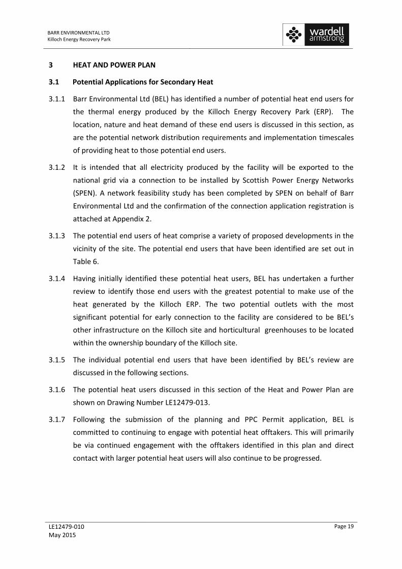
3.1.1 Barr Environmental Ltd (BEL) has identified a number of potential heat end users for
the thermal energy produced by the Killoch Energy Recovery Park (ERP). The
location, nature and heat demand of these end users is discussed in this section, as
are the potential network distribution requirements and implementation timescales
of providing heat to those potential end users.
3.1.2 It is intended that all electricity produced by the facility will be exported to the
national grid via a connection to be installed by Scottish Power Energy Networks
(SPEN). A network feasibility study has been completed by SPEN on behalf of Barr
Environmental Ltd and the confirmation of the connection application registration is
attached at Appendix 2.
3.1.3 The potential end users of heat comprise a variety of proposed developments in the
vicinity of the site. The potential end users that have been identified are set out in
Table 6.
3.1.4 Having initially identified these potential heat users, BEL has undertaken a further
review to identify those end users with the greatest potential to make use of the
heat generated by the Killoch ERP. The two potential outlets with the most
significant potential for early connection to the facility are considered to be BEL’s
other infrastructure on the Killoch site and horticultural greenhouses to be located
within the ownership boundary of the Killoch site.
3.1.5 The individual potential end users that have been identified by BEL’s review are
discussed in the following sections.
3.1.6 The potential heat users discussed in this section of the Heat and Power Plan are
shown on Drawing Number LE12479-013.
3.1.7 Following the submission of the planning and PPC Permit application, BEL is
committed to continuing to engage with potential heat offtakers. This will primarily
be via continued engagement with the offtakers identified in this plan and direct
contact with larger potential heat users will also continue to be progressed.
BARR ENVIRONMENTAL LTD Killoch Energy Recovery Park
LE12479-010 May 2015
Page 20
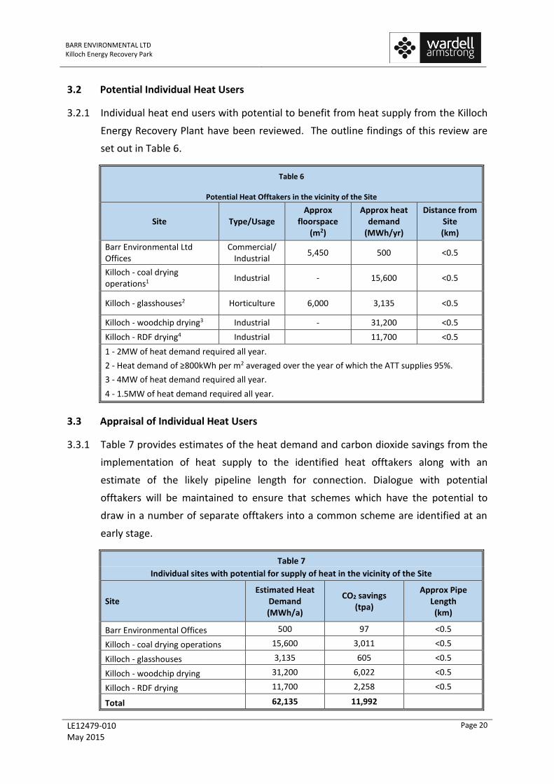
3.2 Potential Individual Heat Users
3.2.1 Individual heat end users with potential to benefit from heat supply from the Killoch
Energy Recovery Plant have been reviewed. The outline findings of this review are
set out in Table 6.
Table 6
Potential Heat Offtakers in the vicinity of the Site
Site Type/Usage Approx
floorspace (m2)
Approx heat demand
(MWh/yr)
Distance from Site (km)
Barr Environmental Ltd Offices
Commercial/ Industrial
5,450 500 <0.5
Killoch - coal drying operations1
Industrial - 15,600 <0.5
Killoch - glasshouses2 Horticulture 6,000 3,135 <0.5
Killoch - woodchip drying3 Industrial - 31,200 <0.5
Killoch - RDF drying4 Industrial 11,700 <0.5
1 - 2MW of heat demand required all year.
2 - Heat demand of ≥800kWh per m2 averaged over the year of which the ATT supplies 95%.
3 - 4MW of heat demand required all year.
4 - 1.5MW of heat demand required all year.
3.3 Appraisal of Individual Heat Users
3.3.1 Table 7 provides estimates of the heat demand and carbon dioxide savings from the
implementation of heat supply to the identified heat offtakers along with an
estimate of the likely pipeline length for connection. Dialogue with potential
offtakers will be maintained to ensure that schemes which have the potential to
draw in a number of separate offtakers into a common scheme are identified at an
early stage.
Table 7
Individual sites with potential for supply of heat in the vicinity of the Site
Site Estimated Heat
Demand (MWh/a)
CO2 savings (tpa)
Approx Pipe Length (km)
Barr Environmental Offices 500 97 <0.5
Killoch - coal drying operations 15,600 3,011 <0.5
Killoch - glasshouses 3,135 605 <0.5
Killoch - woodchip drying 31,200 6,022 <0.5
Killoch - RDF drying 11,700 2,258 <0.5
Total 62,135 11,992
BARR ENVIRONMENTAL LTD Killoch Energy Recovery Park
LE12479-010 May 2015
Page 21
Killoch Area
Barr Environmental Ltd (BEL) Killoch Site
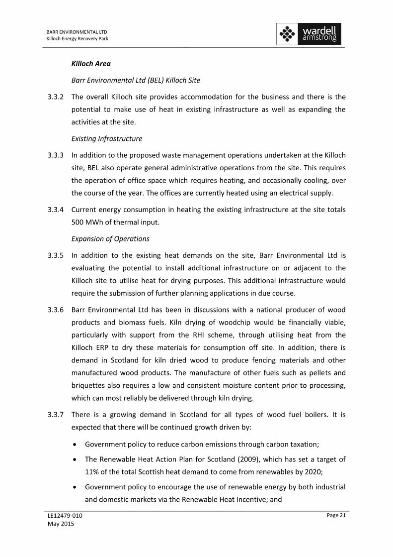
3.3.2 The overall Killoch site provides accommodation for the business and there is the
potential to make use of heat in existing infrastructure as well as expanding the
activities at the site.
Existing Infrastructure
3.3.3 In addition to the proposed waste management operations undertaken at the Killoch
site, BEL also operate general administrative operations from the site. This requires
the operation of office space which requires heating, and occasionally cooling, over
the course of the year. The offices are currently heated using an electrical supply.
3.3.4 Current energy consumption in heating the existing infrastructure at the site totals
500 MWh of thermal input.
Expansion of Operations
3.3.5 In addition to the existing heat demands on the site, Barr Environmental Ltd is
evaluating the potential to install additional infrastructure on or adjacent to the
Killoch site to utilise heat for drying purposes. This additional infrastructure would
require the submission of further planning applications in due course.
3.3.6 Barr Environmental Ltd has been in discussions with a national producer of wood
products and biomass fuels. Kiln drying of woodchip would be financially viable,
particularly with support from the RHI scheme, through utilising heat from the
Killoch ERP to dry these materials for consumption off site. In addition, there is
demand in Scotland for kiln dried wood to produce fencing materials and other
manufactured wood products. The manufacture of other fuels such as pellets and
briquettes also requires a low and consistent moisture content prior to processing,
which can most reliably be delivered through kiln drying.
3.3.7 There is a growing demand in Scotland for all types of wood fuel boilers. It is
expected that there will be continued growth driven by:
Government policy to reduce carbon emissions through carbon taxation;
The Renewable Heat Action Plan for Scotland (2009), which has set a target of
11% of the total Scottish heat demand to come from renewables by 2020;
Government policy to encourage the use of renewable energy by both industrial
and domestic markets via the Renewable Heat Incentive; and

BARR ENVIRONMENTAL LTD Killoch Energy Recovery Park
LE12479-010 May 2015
Page 22
Rising fossil fuel prices which, in particular, affect rural areas which are off gas-
grid and heavily reliant on heating oil.
3.3.8 For kiln drying of woodchip approximately 1MWth would provide sufficient energy
to produce circa 24,000tpa of dry woodchip. Based on discussions with the potential
woodchip supplier, there is the potential to use at least 4 MWth of heat at the
Killoch site for the drying of this material. This operation would be considered an
eligible heat use and would receive RHI payments for the renewable element of the
heat derived from the Killoch ERP.
3.3.9 An area has been identified in the eastern part the Killoch site for the potential
location of kiln drying facilities and woodchip handling area and the technical and
financial feasibility of this development for the offtake of heat will be progressed in
consultation with the woodchip supplier, Scottish Enterprise and the Forestry
Commission.
Coal Drying
3.3.10 Exploratory discussions have been progressed with Hargreaves, the main producer
of coal in Scotland, to develop a coal drying facility adjacent to the Killoch site. The
drying of coal would take place on an aerated pad supplied with heat from the
Killoch ERP and would improve the handling and the calorific value of the coal for
onward supply.
3.3.11 The area adjacent to the Killoch site identified for coal drying also benefits from a
railhead for the transport of coal to and from the drying facility.
3.3.12 Based on discussions with Hargreaves, there is the potential to use at least 2 MWth
of heat at the Killoch site for the drying of coal.
Horticulture
3.3.13 A leading vegetable grower in Scotland has expressed an interest in using the heat as
a source to grow vegetables under glass. Another area has been identified within the
Killoch site where Barr would build the greenhouses and supply the heat and the
vegetable grower would lease the greenhouses, pay a reduced tariff for the supply of
heat and work to develop skills, jobs and outlets for the vegetables.
3.3.14 The typical heat usage for greenhouses growing edible food crops is an average of
550kWth/m2 over the course of a year. Heat usage is predominantly required from
September to April and it is estimated that over 95% of this heat requirement can be

BARR ENVIRONMENTAL LTD Killoch Energy Recovery Park
LE12479-010 May 2015
Page 23
met by the Killoch ERP as the main plant shutdowns will be scheduled for the
summer months.
3.3.15 Based on discussions with the vegetable grower and the area available for the
construction of the greenhouses, there is the potential to use at least 0.45 MWth of
heat at the Killoch site for the heating of the greenhouses. This operation would be
considered an eligible heat use and would receive RHI payments for the renewable
element of the heat derived from the Killoch ERP.
RDF Drying
3.3.16 Another area on the Killoch site has been identified for the installation of RDF drying
facilities. This option is currently being evaluated with respect to the benefits which
can be realised through maximising the thermal input to the plant. This operation
would be considered an eligible heat use and would receive RHI payments for the
renewable element of the heat derived from the Killoch ERP.
3.3.17 As the evaluation of this element of the heat offtake potential is at an early stage, it
has been assumed that the heat used in drying the RDF contributes to the heat
efficiency of the plant and that the electrical efficiency is reduced by the extraction
of this heat as for all other heat uses. The actual impact on overall efficiency will
depend on a number of factors, including the moisture content of the RDF and the
efficiency of the dryers, and further work will be undertaken to quantify these
effects during the detailed design stage of the facility.
3.4 Potential Heat Demand and Assumptions
3.4.1 Initial estimates for the heat demand of the most significant opportunities are in the
region of 50,000 MWh/year. This heat demand represents circa 26% of the total
available annual heat production of the Killoch Facility and circa 89% of the
additional heat export required to meet the long term minimum efficiency
requirements of the Killoch Facility. There is the potential to take more of the heat
output from the Killoch ERP with the facility able to export up to 25MWth. The key
opportunities are identified in Table 8.

BARR ENVIRONMENTAL LTD Killoch Energy Recovery Park
LE12479-010 May 2015
Page 24
Table 8
Summary of Heat Offtakes
Zone Estimated
Heat Demand (MWh/a)
Estimated Heat Demand
(GJ/a)
Percentage of Heat Export
Requirement
Approximate Pipe Length
(m)
Barr Environmental Offices 500 1,800 1% 175
Killoch - coal drying operations 15,600 56,160 28% 225
Killoch - glasshouses 3,135 11,286 6% 300
Killoch - woodchip drying 31,200 112,320 56% 350
Killoch - RDF drying 11,700 42,120 21% 125
TOTALS 62,135 223,686 111% 1,175
3.5 Next Actions
3.5.1 Given the proximity of the Barr Environmental infrastructure to the Killoch ERP,the
proposed offtaker represents a very strong opportunity for supplying heat. This will
require further feasibility studies to ascertain the full potential, but it is recognised
that this is a strong opportunity to help alleviate operational costs for the site as a
whole. The development of other infrastructure to utilise heat, particularly the kiln
drying of wood products and the drying of coal have the potential to deliver
significantly more heat usage. All these opportunities will also be considered with
technical and detailed cost benefit analyses assessments being progressed. Further
planning applications would also be required in due course.
3.5.2 Barr Environmental Ltd will continue their ongoing engagement with council officers
to identify links into other developments in the Killoch and wider area, which could
have the potential to incorporate heating networks during the construction phase.
3.6 Distribution Networks
3.6.1 As well as identifying and securing end users for the heat generated by the Killoch
Energy Recovery Park, one of the primary risks in progressing such a project is being
able to install the requisite distribution network.
3.6.2 The distribution networks for the other potential outlets have not as yet been
established; however, as these are located close to the Killoch Energy Recovery Park,
there are likely to be fewer potential constraints to consider when compared with
areas within cities. The distribution networks associated with these individual end
users continues to be reviewed as part of the development of the business cases for
each scheme component.

BARR ENVIRONMENTAL LTD Killoch Energy Recovery Park
LE12479-010 May 2015
Page 25
3.7 QI and Overall Efficiency for each year of Heat Plan
Table 9
Quality Index for Facility as Heat Exports are secured
Parameter Energy (MWh)
Annual Energy
(GJ)
Equivalent Capacity
(MW)
Percentage of Input Energy
QI at commencement of Heat Plan Period
Qualifying Power Output (CHPQPO) - Facility
63,960 230,256 8.2 20.4%
Useful Heat (CHPQHO) - Facility 0 0 0.0 0.0%
Power Heat
QI Factors (from CHPQA GN44, version 4) 370 130
Efficiencies 20.4% 0.0%
Factored Efficiencies 75.6 0.0
Total Efficiency 20.4%
QI 75.6
QI on development of Heat Uses at Killoch Site (with exception of RDF drying)
Qualifying Power Output (CHPQPO) - Facility
56,143 202,113 7.2 17.9%
Useful Heat (CHPQHO) - Facility 50,435 181,566 6.5 16.1%
Power Heat
Weighted Factors (from Table 6) 370 130
Efficiencies 17.9% 16.1%
Factored Efficiencies 66.4 21.0
Total Efficiency 34.1%
QI 87.4
QI on development of Heat Uses at Killoch Site (with RDF drying)
Qualifying Power Output (CHPQPO) - Facility
54,329 195,585 7.0 17.4%
Useful Heat (CHPQHO) - Facility 62,135 223,686 8.0 19.9%
Power Heat
Weighted Factors (from Table 6) 370 130
Efficiencies 17.4% 19.9%
Factored Efficiencies 64.3 25.8
Total Efficiency 37.2%
QI 90.1
3.8 Implementation Timetable
3.8.1 Table 10, below, gives an indicative timetable for the programme for the
construction of the plant and the roll out of heat distribution.
3.8.2 The exact start date of the construction of any heat distribution system is highly
dependent upon the decisions made for the type of project to be followed. The

BARR ENVIRONMENTAL LTD Killoch Energy Recovery Park
LE12479-010 May 2015
Page 26
development of additional infrastructure at the Killoch site is under Barr
Environmental Ltd’s control subject to receiving the required planning consent.
3.8.3 An indicative implementation programme is set out below, identifying the main
activities which would be required by other parties involved in the implementation
of a heat supply scheme.
3.9 Outcome of Discussions with Local Planners
3.9.1 As part of the development of the Heat and Power Plan, Barr Environmental Ltd
(BEL) have consulted with the most significant development bodies working within
Scotland and the local community, including East Ayrshire Council and Scottish
Power Energy Networks.
3.9.2 In particular, BEL has had specific discussions with:
Hargreaves, with respect to coal drying on a site immediately to the north of the
Killoch site, which benefits from a railhead;
A leading vegetable grower in Scotland, with respect to the development of new
horticultural facility on the Killoch site; and
A national wood products company, with respect to the installation of woodchip
handling and kiln drying facilities for biomass fuel.
3.9.3 The outcome of these discussions with respect to the potential heat offtakes is set
out in more detail in Section 3.3. The discussions will continue to be progressed to
strengthen proposals for individual heat offtakes.
Table 10
Typical Implementation Programme for District Heating Networks
Description Schedule
Obtain Planning Consent and Permit Day 1
Completion of negotiation for supply contracts 9 - 12 months
Start of construction of Facility 3 months
Insert planning application for heat mains 18 months
Start of commissioning of the facility 30 months
Take Over of the plant 36 months
Start of construction of heat system 52 months
Testing of heat network 58 months
Start-up of the heat supply 60 months

BARR ENVIRONMENTAL LTD Killoch Energy Recovery Park
LE12479-010 May 2015
Page 27
3.9.4 As well as continued discussion with these potential partners, BEL will also progress
further consultation with planning and economic development officers to ensure
that where any new developments would benefit from the heat available from the
Killoch ERP plant, these are identified and considered.

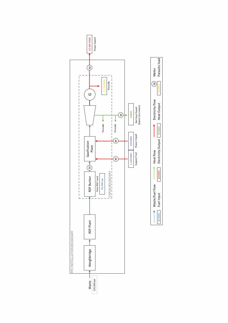
Appendix 1 – Energy Balance and Installation Boundaries
Was
te/f
ue
l flo
wH
eat
flo
wEl
ect
rici
ty f
low
Me
ter
Fue
l In
pu
tEl
ect
rici
ty O
utp
ut
He
at O
utp
ut
Par
asit
ic lo
ad
We
igh
bri
dge
RD
FP
lan
tR
DF
Bu
nke
rW
aste
Gas
ific
atio
nP
lan
tG
Pa
rasi
tic
Pa
rasi
tic
Ne
t H
ea
t Ex
por
t(E
xpo
rt le
ss r
etu
rn)
0 M
Wh
Po
we
rEx
po
rt
63
,96
0 M
Wh
Pa
rasi
tic
11
,70
0 M
Wh
Sup
po
rt F
ue
l
1,1
00
MW
h
Po
we
rIm
por
t
10
0 M
Wh
CH
PQ
A B
OU
ND
AR
Y
Tota
lRD
F In
pu
t
85
,00
0 t
pa
12
0,0
00
tpa
M
M
M
M
M
M
[X] M
Wh
[X] M
Wh
[X] M
Wh
[X] M
Wh
PP
CIN
STA
LLA
TIO
N B
OU
ND
AR
Y

Appendix 2 –
Registration of Application for Scottish Power Energy Networks Connection

Dear Mr. Money
Your application is now registered
Thank you for sending us your completed application. We have now registered your project and your reference number is 0000173466. Our design team will progress your quotation and will contact you within 3 working days to discuss your requirements.
What happens next?
Our enclosed Process Explained diagram shows you the steps to getting you connected and provides guidance to the timescales you can expect.
Need more information?
Useful information and Guidance Leaflets can be found on our website at www.spenergynetworks.co.uk/networkconnections
Get in touch
If you have any questions, please contact us:
Call: 0845 270 0785 (Scotland)
0845 270 0783 (England and Wales)
Email: [email protected]
Just hit reply
If you just hit reply and don’t change the subject header then it will help us direct your email to the right person. Our office hours are Monday – Friday, 8.30am – 4.45pm. We will be in touch again shortly. Regards,
SP Network Connections Contact Team 55 Fullarton Drive Cambuslang Glasgow G32 8FA 0845 270 0785 [email protected] Visit our website www.spenergynetworks.co.uk/networkconnections

============================================================== Please consider the environment before printing this email.
If you have received this message in error, please notify the sender and
immediately delete this message and any attachment hereto and/or copy hereof,
as such message contains confidential information intended solely for the
individual or entity to whom it is addressed. The use or disclosure of such
information to third parties is prohibited by law and may give rise to civil or
criminal liability.
The views presented in this message are solely those of the author(s) and do
not necessarily represent the opinion of Scottish Power, Ltd. or any company of
its group. Neither Scottish Power Ltd. nor any company of its group guarantees
the integrity, security or proper receipt of this message. Likewise, neither
Scottish Power Ltd. nor any company of its group accepts any liability
whatsoever for any possible damages arising from, or in connection with, data
interception, software viruses or manipulation by third parties.
==============================================================

Drawings

Killoch Disposal Point
152.1m
W
a
r
d
B
d
y
156.4m
El Sub Stas
El Sub Sta
Sub Sta
Well
WB
WB
W
a
r
d
B
d
y
Ponds
Conveyor
Tank
155.1m
153.6m
Weighbridges
Killoch
C
o
n
ve
yo
r
A
7
0
W
B
El
S
M
Ordnance Survey, (c) Crown Copyright 2015. All rights reserved. Licence number 100022432
620200
24
76
00
620250
620300
620350
620400
620450
620500
620550
247650
24
77
00
24
77
50
24
78
00
24
78
50
24
79
00
24
79
50
24
80
00
24
80
50
24
81
00
24
81
50
24
82
00
24
82
50
24
83
00
SUB STATION
WEIGHBRIDGES
REFERENCE
APPLICATION SITE
OWNERSHIP BOUNDARY
INDICATIVE CABLE ROUTE (SUBJECT TO
AGREEMENT WITH SP ENERGY NETWORKS)
APPROXIMATE EXTENT OF MRF
DO NOT SCALE FROM THIS DRAWING
Copyright Reservedc
DRG No. SCALE
CHECKED BY APPROVED BYDRAWN BY
CLIENT
PROJECT
DRAWING TITLE
DATE
(HEAD OFFICE)
STOKE-ON-TRENT TEL 0845 111 7777 CARDIFF TEL 029 2072 9191
NEWCASTLE UPON TYNE TEL 0191 232 0943
WEST BROMWICH TEL 0121 580 0909
LONDON TEL 020 7287 2872 TAUNTON TEL 01823 703100
LEIGH TEL 01942 260101
(HEAD OFFICE)
STOKE-ON-TRENT TEL 0845 111 7777 CARDIFF TEL 029 2072 9191
NEWCASTLE UPON TYNE TEL 0191 232 0943 SHEFFIELD TEL 0114 245 6244
WEST BROMWICH TEL 0121 580 0909 EDINBURGH TEL 0131 555 3311
LONDON TEL 020 7287 2872
LEIGH TEL 01942 260101
A3
RKLWSJB
07/05/151:2500 @ A3LE12479-012
Potential Cable Route
East Ayrshire
Barr Killoch Energy Recovery Park,
Barr Environmental Limited
19/05/15 SJB LW RK
AFirst Issue
Crown Copyright.All Rights Reserved.Licence Number ES 100018275

Killoch Disposal Point
152.1m
W
a
r
d
B
d
y
156.4m
El Sub Stas
El Sub Sta
Sub Sta
Well
WB
WB
W
a
r
d
B
d
y
Ponds
Conveyor
Tank
155.1m
153.6m
Weighbridges
Killoch
C
o
n
ve
yo
r
A
7
0
W
B
El
S
M
Ordnance Survey, (c) Crown Copyright 2015. All rights reserved. Licence number 100022432
620200
24
76
00
620250
620300
620350
620400
620450
620500
620550
247650
24
77
00
24
77
50
24
78
00
24
78
50
24
79
00
24
79
50
24
80
00
24
80
50
24
81
00
24
81
50
24
82
00
24
82
50
24
83
00
SUB STATION
WEIGHBRIDGES
RAILHEAD
COAL DRYING
GREENHOUSE
WOOD CHIP
FUEL DRYING
MSW DRYING
REFERENCE
APPLICATION SITE
OWNERSHIP BOUNDARY
APPROXIMATE EXTENT OF MRF
DO NOT SCALE FROM THIS DRAWING
Copyright Reservedc
DRG No. SCALE
CHECKED BY APPROVED BYDRAWN BY
CLIENT
PROJECT
DRAWING TITLE
DATE
(HEAD OFFICE)
STOKE-ON-TRENT TEL 0845 111 7777 CARDIFF TEL 029 2072 9191
NEWCASTLE UPON TYNE TEL 0191 232 0943
WEST BROMWICH TEL 0121 580 0909
LONDON TEL 020 7287 2872 TAUNTON TEL 01823 703100
LEIGH TEL 01942 260101
(HEAD OFFICE)
STOKE-ON-TRENT TEL 0845 111 7777 CARDIFF TEL 029 2072 9191
NEWCASTLE UPON TYNE TEL 0191 232 0943 SHEFFIELD TEL 0114 245 6244
WEST BROMWICH TEL 0121 580 0909 EDINBURGH TEL 0131 555 3311
LONDON TEL 020 7287 2872
LEIGH TEL 01942 260101
A3
RKLWSJB
07/05/151:2500 @ A3LE12479-013
Location of Potential Heat Offtakers
East Ayrshire
Barr Killoch Energy Recovery Park,
Barr Environmental Limited
19/05/15 SJB LW RK
AFirst Issue
Crown Copyright.All Rights Reserved.Licence Number ES 100018275


