07-Dec-11 1 Basics of electrical systems Summary The Basic Capacitor Capacitors are one of the fundamental passive components. In its most basic form, it is composed of two conductive plates separated by an insulating dielectric. The ability to store charge is the definition of capacitance. Dielectric Conductors Summary Dielec tric Pla tes Leads Electrons B A - - - - + + + + - - + + + + - Initially uncharged + - B A - - - - - - - + + + - - - - - - - - - - - - - - + + + + Charging + - B A V S + + + + + + + + + + + - - - - - - - - - - - Fully charged B A V S - + - + - + - + - + - + - + - + - + - + - + Source removed The charging process… A capacitor with stored charge can act as a temporary battery. The Basic Capacitor Capacitance is the ratio of charge to voltage Q C V = Rearranging, the amount of charge on a capacitor is determined by the size of the capacitor (C) and the voltage (V). Q CV = If a 22 μF capacitor is connected to a 10 V source, the charge is 220 μC Capacitance Capacitance An analogy: Imagine you store rubber bands in a bottle that is nearly full. You could store more rubber bands (like charge or Q) in a bigger bottle (capacitance or C) or if you push them in more (voltage or V). Thus, Q CV = A capacitor stores energy in the form of an electric field that is established by the opposite charges on the two plates. The energy of a charged capacitor is given by the equation Capacitance 2 2 1 CV W = where W = the energy in joules C = the capacitance in farads V = the voltage in volts
Transcript
07-Dec-11
1
Basics of electrical systems
Summary
The Basic Capacitor
Capacitors are one of the fundamental passive components. In its most basic form, it is composed of two conductive plates separated by an insulating dielectric.
The ability to store charge is the definition of capacitance.
DielectricConductors
Summary
Dielectric
Plates
Leads
Electrons
BA
−
−
−−
+
+
+
+
−
−
+
+
+
+
−
Initially uncharged
+ −BA
−−
−−
−−
−
+
+
+
−−
−
−
− − − − − −
−
−−−
+
+
+
+
Charging
+ −BA
VS
+
+
+++++++++
−
−
−−−−−−−−−
Fully charged
BA
VS
−+
−+
−+−+−+−+−+−+−+−+−+
Source removed
The charging process…
A capacitor with stored charge can act as a temporary battery.
The Basic CapacitorCapacitance is the ratio of charge to voltage
QC
V=
Rearranging, the amount of charge on a capacitor is determined by the size of the capacitor (C) and the voltage (V).
Q CV=
If a 22 µF capacitor is connected to a 10 V source, the charge is220 µC
Capacitance
Capacitance
An analogy:
Imagine you store rubber bands in a bottle that is nearly full.
You could store more rubber bands (like charge or Q) in a bigger bottle (capacitance or C) or if you push them in more (voltage or V). Thus,
Q CV=
A capacitor stores energy in the form of an electric field that is established by the opposite charges on the two plates. The energy of a charged capacitor is given by the equation
Capacitance
2
21
CVW =
where
W = the energy in joulesC = the capacitance in faradsV = the voltage in volts
07-Dec-11
2
The capacitance of a capacitor depends on three physical characteristics.
Summary
128.85 10 F/m r AC
d
ε− = ×
C is directly proportional to
and the plate area.
the relative dielectric constant
C is inversely proportional to
the distance between the plates
Capacitance
128.85 10 F/m r AC
d
ε− = ×
Summary
Find the capacitance of a 4.0 cm diameter sensor immersed in oil if the plates are separated by 0.25 mm.
The plate area is
The distance between the plates is
Capacitance
( )4.0 for oilrε =
( )( )3 2
123
4.0 1.26 10 m 8.85 10 F/m
0.25 10 mC
−−
−
× = × = ×
30.25 10 m−×
178 pF
( )2 2 3 2π 0.02 m 1.26 10 mA r π −= = = ×
Summary
Capacitor typesMica
MicaFoil
FoilMica
Foil
FoilMica
Foil
Mica capacitors are small with high working voltage. The working voltage is the voltage limit that cannot be exceeded.
Summary
Capacitor types
Ceramic disk
Solder
Lead wire solderedto silver elec trode
Ceramicdielectric
Dipped phenolic coating
Silv er electrodes deposited ontop and bottom of ceramic disk
Ceramic disks are small nonpolarized capacitors They have relatively high capacitance due to high εr.
Plastic film capacitors are small and nonpolarized. They have relatively high capacitance due to larger plate area.
Summary
Capacitor typesElectrolytic (two types)
Symbol for any electrolytic capacitor
Al electrolytic
+
_
Ta electrolytic
Electrolytic capacitors have very high capacitance but they are not as precise as other types and tend to have more leakage current. Electrolytic types are polarized.
07-Dec-11
3
Summary
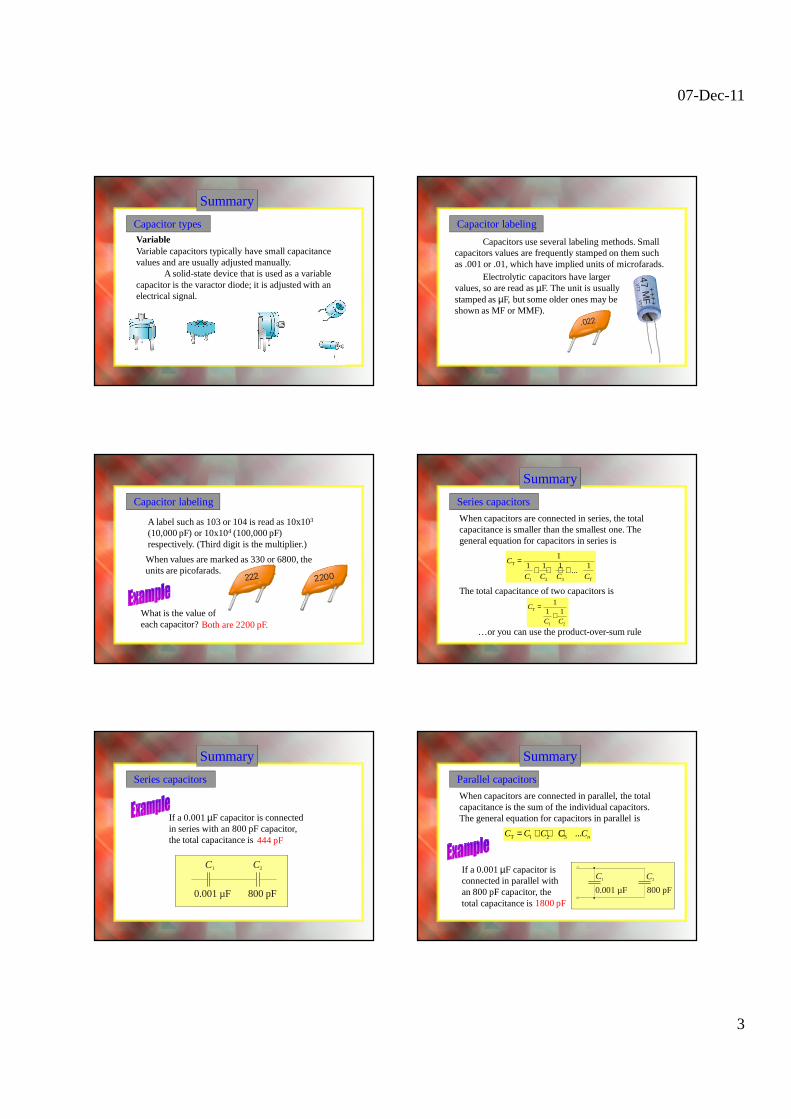
Capacitor typesVariableVariable capacitors typically have small capacitance values and are usually adjusted manually.
A solid-state device that is used as a variable capacitor is the varactor diode; it is adjusted with an electrical signal.
Capacitor labeling
Capacitors use several labeling methods. Small capacitors values are frequently stamped on them such as .001 or .01, which have implied units of microfarads.
+++
+
VT
TV
TT
47 M
F
.022
Electrolytic capacitors have larger values, so are read as µF. The unit is usually stamped as µF, but some older ones may be shown as MF or MMF).
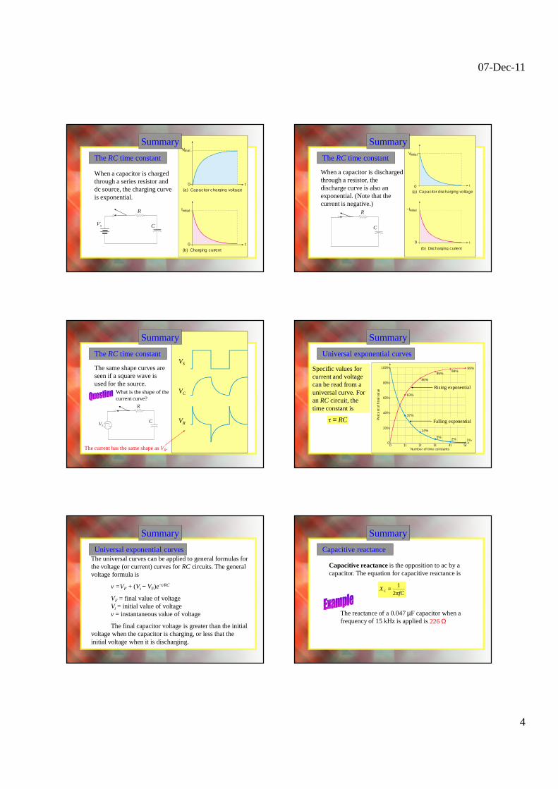
A label such as 103 or 104 is read as 10x103
(10,000 pF) or 10x104 (100,000 pF) respectively. (Third digit is the multiplier.)
Capacitor labeling
When values are marked as 330 or 6800, the units are picofarads.
What is the value of each capacitor? Both are 2200 pF.
222 2200
Summary
Series capacitors
When capacitors are connected in series, the total capacitance is smaller than the smallest one. The general equation for capacitors in series is
T
1 2 3 T
11 1 1 1
...C
C C C C
=+ + + +
The total capacitance of two capacitors is
T
1 2
11 1
C
C C
=+
…or you can use the product-over-sum rule
Summary
Series capacitors
If a 0.001 µF capacitor is connected in series with an 800 pF capacitor, the total capacitance is444 pF
0.001 µF 800 pF
C1 C2
Summary
Parallel capacitors
When capacitors are connected in parallel, the total capacitance is the sum of the individual capacitors. The general equation for capacitors in parallel is
T 1 2 3 ... nC C C C C= + + +
1800 pF
If a 0.001 µF capacitor is connected in parallel with an 800 pF capacitor, the total capacitance is
0.001 µF 800 pF
C1 C2
07-Dec-11
4
Summary
The RC time constant
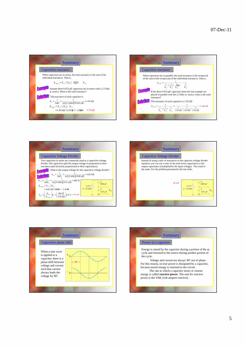
When a capacitor is charged through a series resistor and dc source, the charging curve is exponential.
C
R Iinitial
t0(b) Charging current
Vfinal
t0(a) Capacitor charging voltage
Summary
When a capacitor is discharged through a resistor, the discharge curve is also an exponential. (Note that the current is negative.)
t
t
−Iinitial
0
(b) Discharging current
Vinitial
0(a) Capacitor discharging voltage
C
R
The RC time constant
Summary
The same shape curves are seen if a square wave is used for the source.
VS
VC
VRC
R
VS
What is the shape of the current curve?
The current has the same shape as VR.
The RC time constant
Summary
Universal exponential curves
Specific values for current and voltage can be read from a universal curve. For an RC circuit, the time constant is
τ RC=
100%
80%
60%
40%
20%
00 1τ 2τ 3τ 4τ 5τ
99%98%
95%
86%
63%
37%
14%
5% 2% 1%
Number of time constants
Per
cent
of f
inal
val
ue
Rising exponential
Falling exponential
Summary
The universal curves can be applied to general formulas for the voltage (or current) curves for RC circuits. The general voltage formula is
v =VF + (Vi − VF)e−t/RC
VF = final value of voltageVi = initial value of voltagev = instantaneous value of voltage
The final capacitor voltage is greater than the initial voltage when the capacitor is charging, or less that the initial voltage when it is discharging.
Universal exponential curves
Summary
Capacitive reactance
Capacitive reactance is the opposition to ac by a capacitor. The equation for capacitive reactance is
12πCX
fC=
The reactance of a 0.047 µF capacitor when a frequency of 15 kHz is applied is 226 Ω
07-Dec-11
5
Summary
Capacitive reactance
When capacitors are in series, the total reactance is the sum of the individual reactances. That is,
Assume three 0.033 µF capacitors are in series with a 2.5 kHz ac source. What is the total reactance?
5.79 kΩ
C( ) C1 C2 C3 Ctot nX X X X X= + + +⋅⋅⋅+
The reactance of each capacitor is
( ) ( )1 1
1.93 k2π 2π 2.5 kHz 0.033 µFCX
fC= = = Ω
C( ) C1 C2 C3
1.93 k 1.93 k 1.93 k
totX X X X= + +
= Ω + Ω + Ω =
Summary
Capacitive reactance
When capacitors are in parallel, the total reactance is the reciprocal of the sum of the reciprocals of the individual reactances. That is,
If the three 0.033 µF capacitors from the last example are placed in parallel with the 2.5 kHz ac source, what is the total reactance?
643 Ω
C( )
C1 C2 C3 C
11 1 1 1tot
n
X
X X X X
=+ + + ⋅⋅⋅ +
The reactance of each capacitor is 1.93 kΩ
C( )
C1 C2 C3
1 11 1 1 1 1 1
+ +1.93 k 1.93 k 1.93 k
totX
X X X
= = =+ +
Ω Ω Ω
Summary
Capacitive Voltage DividerTwo capacitors in series are commonly used as a capacitive voltage divider. The capacitors split the output voltage in proportion to their reactance (and inversely proportional to their capacitance).
What is the output voltage for the capacitive voltage divider?
Vout
( )( )11
1 14.82 k
2π 2π 33 kHz 1000 pFCXfC
= = = Ω
( )( )22
1 1482
2π 2π 33 kHz 0.01 µFCXfC
= = = Ω1000 pF
0.01 µFC2
C1
1.0 Vf = 33 kHz
2
( )
482 1.0 V =
5.30 kC
out sC tot
XV V
X
Ω = = Ω
( ) 1 2
4.82 k 482 5.30 kC tot C CX X X= +
= Ω + Ω = Ω
91 mV
Summary
Capacitive Voltage DividerInstead of using a ratio of reactances in the capacitor voltage divider equation, you can use a ratio of the total series capacitance to the output capacitance (multiplied by the input voltage). The result is the same. For the problem presented in the last slide,
Vout
( )( )1 2( )
1 2
1000 pF 0.01 µF909 pF
1000 pF 0.01 µFtot
C CC
C C= = =
+ +
1000 pF
0.01 µFC2
C1
1.0 Vf = 33 kHz
( )
2
909 pF1.0 V =
0.01 µFtot
out s
CV V
C
= =
91 mV
Summary
Capacitive phase shift
When a sine wave is applied to a capacitor, there is a phase shift between voltage and current such that current always leads the voltage by 90o.
VC0
I 0
90o
Summary
Power in a capacitor
Voltage and current are always 90o out of phase. For this reason, no true power is dissipated by a capacitor, because stored energy is returned to the circuit.
The rate at which a capacitor stores or returns energy is called reactive power. The unit for reactive power is the VAR (volt-ampere reactive).
Energy is stored by the capacitor during a portion of the ac cycle and returned to the source during another portion of the cycle.
07-Dec-11
6
Summary
Power supply filtering
There are many applications for capacitors. One is in filters, such as the power supply filter shown here.
Rectifier
60 Hz acC Load
resistance
The filter smoothes the pulsating dc from the rectifier.
Summary
Coupling capacitors
Coupling capacitors are used to pass an ac signal from one stage to another while blocking dc.
The capacitor isolates dc between the amplifier stages, preventing dc in one stage from affecting the other stage.
0 V 0 V
3 V
Amplifierstage 1
Amplifierstage 2
R2
R1C
+V
Input Output
Summary
Bypass capacitors
Another application is to bypass an ac signal to ground but retain a dc value. This is widely done to affect gain in amplifiers.
The bypass capacitor places point A at ac ground, keeping only a dc value at point A. R2
R1
C
0 V
dc plusac
Point in circuit whereonly dc is required
0 V
dc only
A
Selected Key Terms
Capacitor
Dielectric
Farad
RC time constant
An electrical device consisting of two conductive plates separated by an insulating material and possessing the property of capacitance.
The insulating material between the conductive plates of a capacitor.
The unit of capacitance.
A fixed time interval set by the R and C values, that determine the time response of a series RCcircuit. It equals the product of the resistance and the capacitance.
Capacitive reactance
Instantaneous power (p)
True power (Ptrue)
Reactive power (Pr )
VAR (volt-ampere
reactive)
The value of power in a circuit at a given instant of time.
The power that is dissipated in a circuit usually in the form of heat.
The opposition of a capacitor to sinusoidal current. The unit is the ohm.
Selected Key Terms
The rate at which energy is alternately stored and returned to the source by a capacitor. The unit is the VAR.
The unit of reactive power.
Quiz
1. The capacitance of a capacitor will be larger if
a. the spacing between the plates is increased.
b. air replaces oil as the dielectric.
c. the area of the plates is increased.
d. all of the above.
07-Dec-11
7
Quiz
2. The major advantage of a mica capacitor over other types is
a. they have the largest available capacitances.
b. their voltage rating is very high
c. they are polarized.
d. all of the above.
Quiz
3. Electrolytic capacitors are useful in applications where
a. a precise value of capacitance is required.
b. low leakage current is required.
c. large capacitance is required.
d. all of the above.
Quiz
4. If a 0.015 µF capacitor is in series with a 6800 pF capacitor, the total capacitance is
a. 1568 pF.
b. 4678 pF.
c. 6815 pF.
d. 0.022 µF.
Quiz
5. Two capacitors that are initially uncharged are connected in series with a dc source. Compared to the larger capacitor, the smaller capacitor will have
a. the same charge.
b. more charge.
c. less voltage.
d. the same voltage.
Quiz
6. When a capacitor is connected through a resistor to a dc voltage source, the charge on the capacitor will reach 50% of its final charge in
a. less than one time constant.
b. exactly one time constant.
c. greater than one time constant.
d. answer depends on the amount of voltage.
Quiz
7. When a capacitor is connected through a series resistor and switch to a dc voltage source, the voltage across the resistor after the switch is closed has the shape of
a. a straight line.
b. a rising exponential.
c. a falling exponential.
d. none of the above.
07-Dec-11
8
Quiz
8. The capacitive reactance of a 100 µF capacitor to 60 Hz is
a. 6.14 kΩ.
b. 265 Ω.
c. 37.7 Ω.
d. 26.5 Ω
Quiz
9. If an sine wave from a function generator is applied to a capacitor, the current will
a. lag voltage by 90o.
b. lag voltage by 45o.
c. be in phase with the voltage.
d. none of the above.
Quiz
10. A switched capacitor emulates a
a. smaller capacitor.
b. larger capacitor.
c. battery.
d. resistor.
Quiz
Answers:
1. c
2. b
3. c
4. b
5. a
6. a
7. c
8. d
9. d
10. d
Summary
Sinusoidal response of RC circuits
When both resistance and capacitance are in a series circuit, the phase angle between the applied voltage and total current is between 0° and 90°, depending on the values of resistance and reactance.
R
VR
C
VR leads VS VC lags VS
I leads VS
I
VS
VC
Summary
Impedance of series RC circuits
In a series RC circuit, the total impedance is the phasor sum of R and XC.
R is plotted along the positive x-axis.
R
XC is plotted along the negative y-axis.
XC
1tan CX
Rθ − =
Z
It is convenient to reposition the phasors into the impedance triangle.
R
XC
Z
Z is the diagonalθ θ
07-Dec-11
9
Summary
Impedance of series RC circuits
R = 1.2 kΩ
XC = 960 Ω
Sketch the impedance triangle and show the values for R = 1.2 kΩ and XC = 960 Ω.
( ) ( )2 21.2 k + 0.96 k
1.33 k
Z = Ω Ω
= Ω
1 0.96 ktan
1.2 k39
θ − Ω=Ω
= °Z = 1.33 kΩ
39oθ
Summary
Analysis of series RC circuits
Ohm’s law is applied to series RC circuits using Z, V, and I.
V V
V IZ I ZZ I
= = =
Because I is the same everywhere in a series circuit, you can obtain the voltages across different components by multiplying the impedance of that component by the current as shown in the following example.
Summary
Analysis of series RC circuits
Assume the current in the previous example is 10 mArms. Sketch the voltage phasor diagram. The impedance triangle from the previous example is shown for reference.
VR = 12 V
VC = 9.6 V
The voltage phasor diagram can be found from Ohm’s law. Multiply each impedance phasor by 10 mA.
x 10 mA=
R = 1.2 kΩ
XC = 960 ΩZ = 1.33 kΩ
39o
VS = 13.3 V
39oθ θ
Summary
Variation of phase angle with frequency
Phasor diagrams that have reactance phasors can only be drawn for a single frequency because X is a function of frequency. As frequency changes, the impedance triangle for an RC circuit changes as illustrated here because XC decreases with increasing f. This determines the frequency response of RC circuits.
θ
Z3
XC1
XC2
XC3
Z2
Z1
12
3
1
2
f
f
f
3
Increasing fθ
θ
R
θ
(phase lag)
φ
φ
(phase lag)
V
Summary
Applications
RVR
Vout
C VoutVin
Vin
Vout
Vin
For a given frequency, a series RC circuit can be used to produce a phase lag by a specific amount between an input voltage and an output by taking the output across the capacitor. This circuit is also a basic low-pass filter, a circuit that passes low frequencies and rejects all others.
θ
θ
(phase lead)
(phase lead)
V
Summary
Applications
R
VC
VoutC
VoutVin
Vin
Vout
Vin
Reversing the components in the previous circuit produces a circuit that is a basic lead network. This circuit is also a basic high-pass filter, a circuit that passes high frequencies and rejects all others. This filter passes high frequencies down to a frequency called the cutoff frequency.
07-Dec-11
10
Summary
Applications
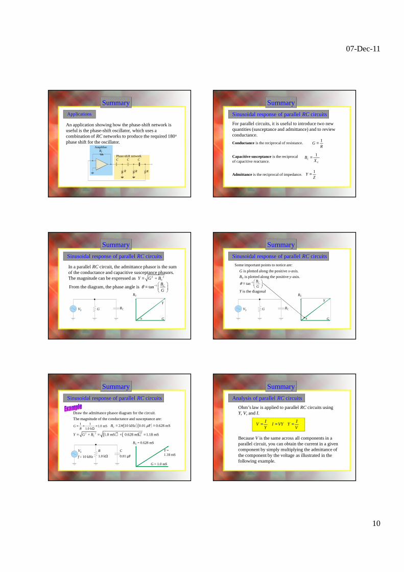
An application showing how the phase-shift network is useful is the phase-shift oscillator, which uses a combination of RC networks to produce the required 180o
phase shift for the oscillator.Amplifier
Rf
R R R
C C CPhase-shift network
Summary
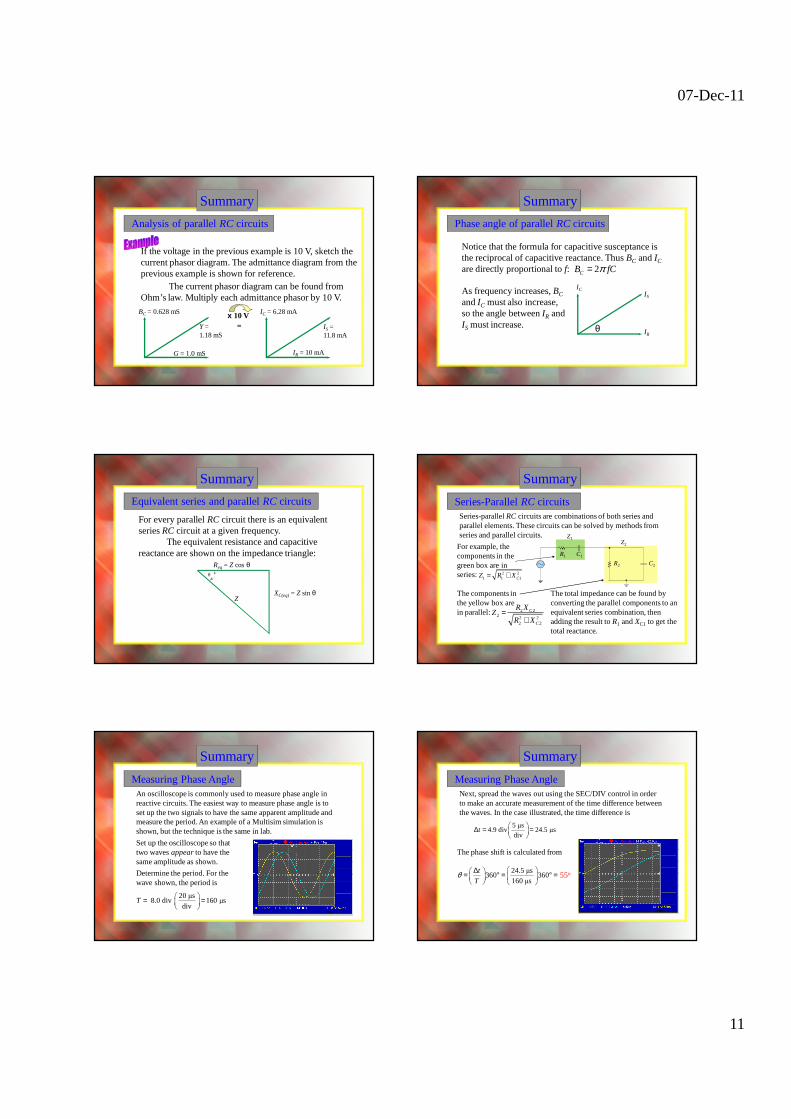
Sinusoidal response of parallel RC circuits
For parallel circuits, it is useful to introduce two new quantities (susceptance and admittance) and to review conductance.
Conductance is the reciprocal of resistance. 1
GR
=
Admittance is the reciprocal of impedance.
Capacitive susceptance is the reciprocal of capacitive reactance.
1C
C
BX
=
1Y
Z=
Summary
Sinusoidal response of parallel RC circuits
In a parallel RC circuit, the admittance phasor is the sum of the conductance and capacitive susceptance phasors. The magnitude can be expressed as 2 2 + CY G B=
VS G BC
Y
G
BC
θ
From the diagram, the phase angle is 1tan CB
Gθ − =
Summary
Sinusoidal response of parallel RC circuits
VS G BC
Y
G
BC
θ
G is plotted along the positive x-axis.
BC is plotted along the positive y-axis. 1tan CB
Gθ − =
Y is the diagonal
Some important points to notice are:
Summary
Sinusoidal response of parallel RC circuits
VS C
0.01 µF
Y = 1.18 mS
G = 1.0 mS
BC = 0.628 mS
Draw the admittance phasor diagram for the circuit.
f = 10 kHz
R
1.0 kΩ
1 11.0 mS
1.0 kG
R= = =
Ω( ) ( )2 10 kHz 0.01 F 0.628 mSCB π µ= =
The magnitude of the conductance and susceptance are:
( ) ( )2 22 2 + 1.0 mS + 0.628 mS 1.18 mSCY G B= = =
Summary
Analysis of parallel RC circuits
Ohm’s law is applied to parallel RC circuits using Y, V, and I.
I I
V I VY YY V
= = =
Because V is the same across all components in a parallel circuit, you can obtain the current in a given component by simply multiplying the admittance of the component by the voltage as illustrated in the following example.
07-Dec-11
11
Summary
Analysis of parallel RC circuits
If the voltage in the previous example is 10 V, sketch the current phasor diagram. The admittance diagram from the previous example is shown for reference.
The current phasor diagram can be found from Ohm’s law. Multiply each admittance phasor by 10 V.
x 10 V=Y =
1.18 mS
G = 1.0 mS
BC = 0.628 mS
IR = 10 mA
IC = 6.28 mA
IS = 11.8 mA
Summary
Phase angle of parallel RC circuits
Notice that the formula for capacitive susceptance is the reciprocal of capacitive reactance. Thus BC and IC
are directly proportional to f: 2CB fCπ=
IR
ICIS
θ
As frequency increases, BC
and IC must also increase, so the angle between IR and IS must increase.
Summary
Equivalent series and parallel RC circuits
For every parallel RC circuit there is an equivalent series RC circuit at a given frequency.
The equivalent resistance and capacitive reactance are shown on the impedance triangle:
Z
Req = Z cos θ
XC(eq) = Z sin θ
θ
Summary
Series-Parallel RC circuitsSeries-parallel RC circuits are combinations of both series and parallel elements. These circuits can be solved by methods from series and parallel circuits.
For example, the components in the green box are in series:
The components in the yellow box are in parallel: 2 2
2 2 22 2
C
C
R XZ
R X=
+
R1 C1
R2 C2
Z1Z2
The total impedance can be found by converting the parallel components to an equivalent series combination, then adding the result to R1 and XC1 to get the total reactance.
2 21 1 1CZ R X= +
Summary
Measuring Phase AngleAn oscilloscope is commonly used to measure phase angle in reactive circuits. The easiest way to measure phase angle is to set up the two signals to have the same apparent amplitude and measure the period. An example of a Multisim simulation is shown, but the technique is the same in lab.
Set up the oscilloscope so that two waves appear to have the same amplitude as shown.
Determine the period. For the wave shown, the period is
20 µs 8.0 div 160 µs
divT
= =
Summary
Measuring Phase AngleNext, spread the waves out using the SEC/DIV control in order to make an accurate measurement of the time difference between the waves. In the case illustrated, the time difference is
5 µs4.9 div 24.5 µs
divt
∆ = =
The phase shift is calculated from
24.5 µs360 360
160 µs
t
Tθ ∆ = ° = ° =
55o
07-Dec-11
12
Summary
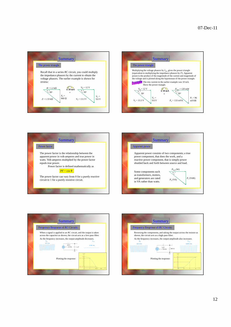
The power triangle
Recall that in a series RC circuit, you could multiply the impedance phasors by the current to obtain the voltage phasors. The earlier example is shown for review:
VR = 12 V
VC = 9.6 V
x 10 mA=
R = 1.2 kΩ
XC = 960 ΩZ = 1.33 kΩ
39o
VS = 13.3 V
39oθ θ
Summary
The power triangle
Multiplying the voltage phasors by Irms gives the power triangle (equivalent to multiplying the impedance phasors by I2). Apparent power is the product of the magnitude of the current and magnitude of the voltage and is plotted along the hypotenuse of the power triangle.
The rms current in the earlier example was 10 mA. Show the power triangle.
Ptrue = 120 mW
Pr = 96 mVAR
x 10 mA= 39o
Pa = 133 mVA
VR = 12 V
VC = 9.6 VVS = 13.3 V
39oθ θ
Summary
Power factor
The power factor is the relationship between the apparent power in volt-amperes and true power in watts. Volt-amperes multiplied by the power factor equals true power.
Power factor is defined mathematically as
PF = cos θ
The power factor can vary from 0 for a purely reactive circuit to 1 for a purely resistive circuit.
Summary
Apparent power
Apparent power consists of two components; a true power component, that does the work, and a reactive power component, that is simply power shuttled back and forth between source and load.
Ptrue (W)
Pr (VAR)
Some components such as transformers, motors, and generators are rated in VA rather than watts.
Pa (VA)
θ
10 V dc
VoutV in
100 Ω1 Fµ
10 V dc
0
10 V dc
0
Summary
Frequency Response of RC Circuits
When a signal is applied to an RC circuit, and the output is taken across the capacitor as shown, the circuit acts as a low-pass filter.
As the frequency increases, the output amplitude decreases.
Plotting the response:
Vout (V)
9.98
8.46
1.570.79
0.1 1 10 20 100f (kHz)
9
8
7
6
5
4
3
2
1
1ƒ = 1 kHz
8.46 V rms10 V rms Ω100 Fµ
1.57 V rms
10 V rms
1ƒ = 10 kHzΩ100
Fµ0.79 V rms
10 V rms
1ƒ = 20 kHzΩ100
Fµ
Vin
10 V dc
0
Vout
0 V dc10 V dc 100 Ω1 Fµ
Summary
Frequency Response of RC Circuits
Reversing the components, and taking the output across the resistor as shown, the circuit acts as a high-pass filter.
As the frequency increases, the output amplitude also increases.
Plotting the response:
ƒ = 100 Hz
0.63 V rms10 V rms
100 Ω1 Fµ
ƒ = 1 kHz
5.32 V rms10 V rms
100 Ω1 Fµ
ƒ = 10 kHz
9.87 V rms10 V rms
100 Ω1 Fµ
Vout (V)
f (kHz)
9.87
5.32
0.6300.01 0.1 1
10
98
7
6
5
4
3
21
10
07-Dec-11
13
Impedance
Phase angle
Capacitive suceptance (BC)
Admittance (Y)
The total opposition to sinusoidal current expressed in ohms.
Selected Key Terms
The ability of a capacitor to permit current; the reciprocal of capacitive reactance. The unit is the siemens (S).
The angle between the source voltage and the total current in a reactive circuit.
A measure of the ability of a reactive circuit to permit current; the reciprocal of impedance. The unit is the siemens (S).
Power factor
Frequency response
Cutoff frequency
The frequency at which the output voltage of a filter is 70.7% of the maximum output voltage.
In electric circuits, the variation of the output voltage (or current) over a specified range of frequencies.
The relationship between volt-amperes and true power or watts. Volt-amperes multiplied by the power factor equals true power.
Selected Key Terms
Quiz
1. If you know what the impedance phasor diagram looks like in a series RC circuit, you can find the voltage phasor diagram by
a. multiplying each phasor by the current
b. multiplying each phasor by the source voltage
c. dividing each phasor by the source voltage
d. dividing each phasor by the current
Quiz
2. A series RC circuit is driven with a sine wave. If the output voltage is taken across the resistor, the output will
a. be in phase with the input.
b. lead the input voltage.
c. lag the input voltage.
d. none of the above
Quiz
3. A series RC circuit is driven with a sine wave. If you measure 7.07 V across the capacitor and 7.07 V across the resistor, the voltage across both components is
a. 0 V
b. 5 V
c. 10 V
d. 14.1 V
Quiz
4. If you increase the frequency in a series RC circuit,
a. the total impedance will increase
b. the reactance will not change
c. the phase angle will decrease
d. none of the above
07-Dec-11
14
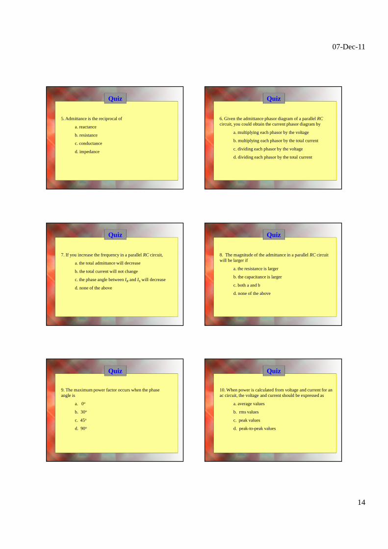
Quiz
5. Admittance is the reciprocal of
a. reactance
b. resistance
c. conductance
d. impedance
Quiz
6. Given the admittance phasor diagram of a parallel RCcircuit, you could obtain the current phasor diagram by
a. multiplying each phasor by the voltage
b. multiplying each phasor by the total current
c. dividing each phasor by the voltage
d. dividing each phasor by the total current
Quiz
7. If you increase the frequency in a parallel RC circuit,
a. the total admittance will decrease
b. the total current will not change
c. the phase angle between IR and IS will decrease
d. none of the above
Quiz
8. The magnitude of the admittance in a parallel RC circuit will be larger if
a. the resistance is larger
b. the capacitance is larger
c. both a and b
d. none of the above
Quiz
9. The maximum power factor occurs when the phase angle is
a. 0o
b. 30o
c. 45o
d. 90o
Quiz
10. When power is calculated from voltage and current for an ac circuit, the voltage and current should be expressed as
a. average values
b. rms values
c. peak values
d. peak-to-peak values
07-Dec-11
15
Quiz
Answers:
1. a
2. b
3. c
4. c
5. d
6. a
7. d
8. d
9. a
10. b
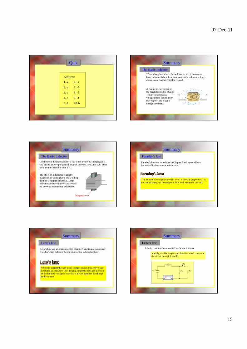
When a length of wire is formed into a coil., it becomes a basic inductor. When there is current in the inductor, a three-dimensional magnetic field is created.
Summary
The Basic Inductor
A change in current causes the magnetic field to change. This in turn induces a voltage across the inductor that opposes the original change in current.
NS
Summary
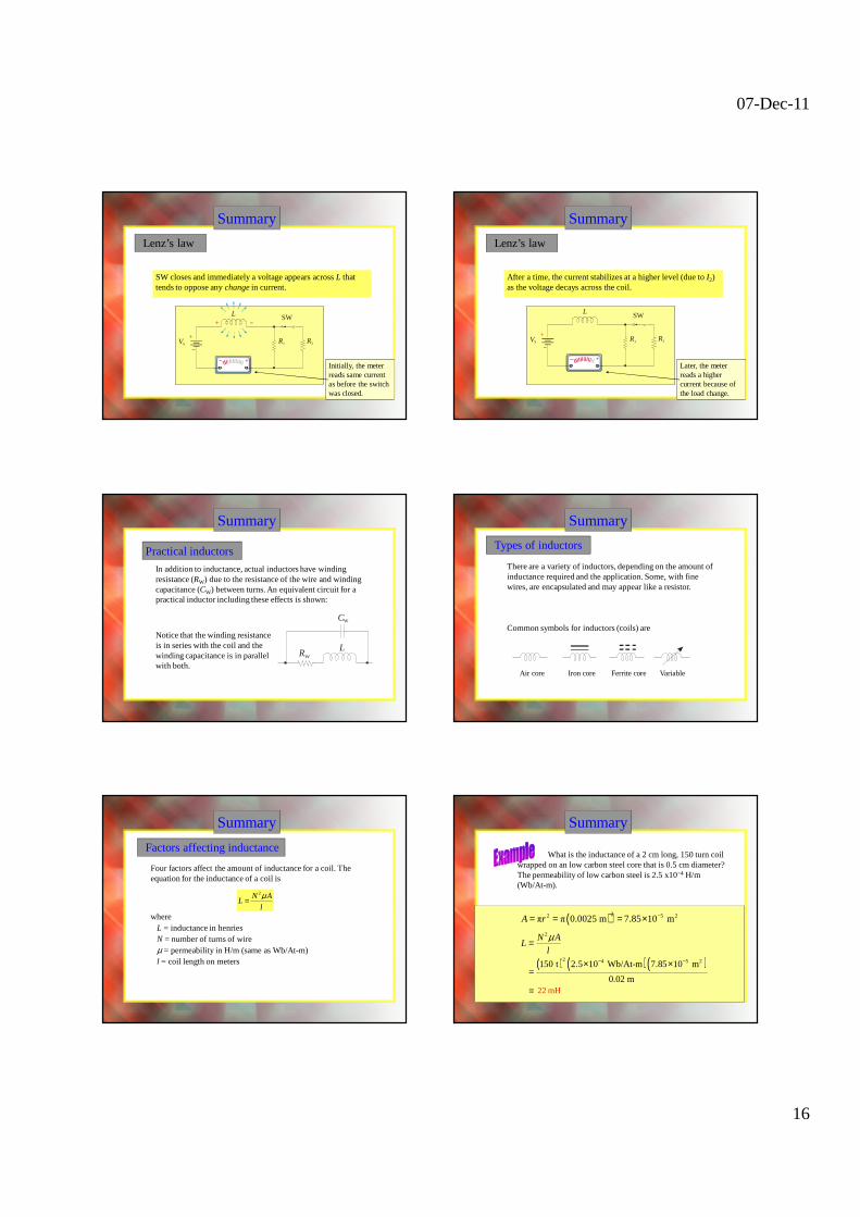
The Basic Inductor
The effect of inductance is greatly magnified by adding turns and winding them on a magnetic material. Large inductors and transformers are wound on a core to increase the inductance.
Magnetic core
One henry is the inductance of a coil when a current, changing at a rate of one ampere per second, induces one volt across the coil. Most coils are much smaller than 1 H.
Summary
Faraday’s law
Faraday’s law was introduced in Chapter 7 and repeated here because of its importance to inductors.
The amount of voltage induced in a coil is directly proportional to the rate of change of the magnetic field with respect to the coil.
Summary
Lenz’s law
Lenz’s law was also introduced in Chapter 7 and is an extension of Faraday’s law, defining the direction of the induced voltage:
When the current through a coil changes and an induced voltage is created as a result of the changing magnetic field, the direction of the induced voltage is such that it always opposes the change in the current.
Summary
Lenz’s law
A basic circuit to demonstrate Lenz’s law is shown.
Initially, the SW is open and there is a small current in the circuit through L and R1.
−R1
SW
R2VS
L
+
− +
07-Dec-11
16
Summary
SW closes and immediately a voltage appears across L that tends to oppose any change in current.
−
−
R1
SW
R2VS
L
+
+
− +Initially, the meter reads same current as before the switch was closed.
Lenz’s law
Summary
After a time, the current stabilizes at a higher level (due to I2) as the voltage decays across the coil.
+−
−R1
SW
R2VS
L
+
Lenz’s law
Later, the meter reads a higher current because of the load change.
Summary
Practical inductors
In addition to inductance, actual inductors have winding resistance (RW) due to the resistance of the wire and winding capacitance (CW) between turns. An equivalent circuit for a practical inductor including these effects is shown:
LRW
CW
Notice that the winding resistance is in series with the coil and the winding capacitance is in parallel with both.
Summary
Types of inductors
Common symbols for inductors (coils) are
Air core Iron core Ferrite core Variable
There are a variety of inductors, depending on the amount of inductance required and the application. Some, with fine wires, are encapsulated and may appear like a resistor.
Summary
Factors affecting inductance
Four factors affect the amount of inductance for a coil. The equation for the inductance of a coil is
2N AL
l
µ=
where L = inductance in henriesN = number of turns of wireµ = permeability in H/m (same as Wb/At-m) l = coil length on meters
Summary
What is the inductance of a 2 cm long, 150 turn coil wrapped on an low carbon steel core that is 0.5 cm diameter? The permeability of low carbon steel is 2.5 x10⁻⁴ H/m (Wb/At-m).
( )22 5 2π π 0.0025 m 7.85 10 mA r −= = = ×
2N AL
l
µ=
22 mH
( ) ( )( )2 4 5 2150 t 2.5 10 Wb/At-m 7.85 10 m
0.02 m
− −× ×=
=
07-Dec-11
17
Summary
Practical inductors
Inductors come in a variety of sizes. A few common ones are shown here.
Encapsulated Torroid coil Variable
Summary
Series inductorsWhen inductors are connected in series, the total inductance is the sum of the individual inductors. The general equation for inductors in series is
2.18 mH
T 1 2 3 ... nL L L L L= + + +
If a 1.5 mH inductor is connected in series with an 680 µH inductor, the total inductance is
L1 L2
1.5 mH 680 Hµ
Summary
Parallel inductorsWhen inductors are connected in parallel, the total inductance is smaller than the smallest one. The general equation for inductors in parallel is
The total inductance of two inductors is
…or you can use the product-over-sum rule.
T
1 2 3 T
11 1 1 1
...L
L L L L
=+ + + +
T
1 2
11 1
L
L L
=+
Summary
Parallel inductors
If a 1.5 mH inductor is connected in parallel with an 680 µH inductor, the total inductance is 468 µH
L1 L2
1.5 mH 680 Hµ
Summary
Inductors in dc circuits
When an inductor is connected in series with a resistor and dc source, the current change is exponential.
R
L
t0Current after switch closure
t0 Inductor voltage after switch closure
Vinitial
Ifinal
Summary
Inductors in dc circuits
The same shape curves are seen if a square wave is used for the source. Pulse response is covered further in Chapter 20.
VS
VL
VR
R
LVS
07-Dec-11
18
Summary
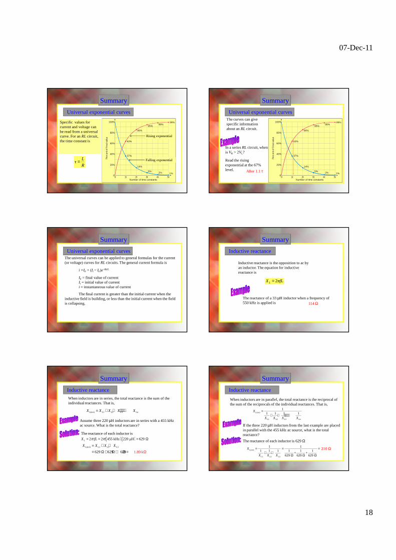
Universal exponential curves
Specific values for current and voltage can be read from a universal curve. For an RL circuit, the time constant is
τL
R=
100%
80%
60%
40%
20%
00 1τ 2τ 3τ 4τ 5τ
99%98%
95%
86%
63%
37%
14%
5% 2% 1%
Number of time constants
Per
cent
of f
inal
val
ue
Rising exponential
Falling exponential
In a series RL circuit, when is VR > 2VL?
Summary
100%
80%
60%
40%
20%
00 1τ 2τ 3τ 4τ 5τ
99%98%
95%
86%
63%
37%
14%
5% 2% 1%
Number of time constants
Per
cent
of f
inal
val
ue
Read the rising exponential at the 67% level. After 1.1 τ
The curves can give specific information about an RL circuit.
Universal exponential curves
Summary
The universal curves can be applied to general formulas for the current (or voltage) curves for RL circuits. The general current formula is
i =IF + (Ii − IF)e−Rt/L
IF = final value of currentIi = initial value of currenti = instantaneous value of current
The final current is greater than the initial current when the inductive field is building, or less than the initial current when the field is collapsing.
Universal exponential curves
Summary
Inductive reactance
Inductive reactance is the opposition to ac by an inductor. The equation for inductive reactance is
The reactance of a 33 µH inductor when a frequency of 550 kHz is applied is 114 Ω
2πLX fL=
Summary
Inductive reactance
When inductors are in series, the total reactance is the sum of the individual reactances. That is,
Assume three 220 µH inductors are in series with a 455 kHz ac source. What is the total reactance?
1.89 kΩ
L( ) L1 L2 L3 Ltot nX X X X X= + + + ⋅⋅⋅ +
The reactance of each inductor is
( )( )L 2 2 455 kHz 220 µH 629 X fLπ π= = = Ω
L( ) L1 L2 L3
629 629 629
totX X X X= + +
= Ω + Ω + Ω =
Summary
Inductive reactance
When inductors are in parallel, the total reactance is the reciprocal of the sum of the reciprocals of the individual reactances. That is,
If the three 220 µH inductors from the last example are placed in parallel with the 455 kHz ac source, what is the total reactance?
210 Ω
L( )
L1 L2 L3 L
11 1 1 1tot
n
X
X X X X
=+ + + ⋅⋅⋅+
The reactance of each inductor is 629 Ω
L( )
L1 L2 L3
1 11 1 1 1 1 1
+ +629 629 629
totX
X X X
= = =+ +
Ω Ω Ω
07-Dec-11
19
Summary
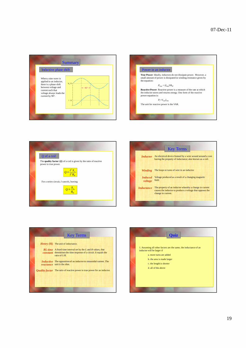
Inductive phase shift
When a sine wave is applied to an inductor, there is a phase shift between voltage and current such that voltage always leads the current by 90o.
VL 0
0
90°
I
True Power: Ideally, inductors do not dissipate power. However, a small amount of power is dissipated in winding resistance given by the equation:
Ptrue = (Irms)2RW
Reactive Power: Reactive power is a measure of the rate at which the inductor stores and returns energy. One form of the reactive power equation is:
Pr=VrmsIrms
The unit for reactive power is the VAR.
Power in an inductor
Thequality factor (Q) of a coil is given by the ratio of reactive power to true power.
Q of a coil
2
2L
W
I XQ
I R=
For a series circuit, I cancels, leaving
L
W
XQ
R=
Inductor
Winding
Induced voltage
Inductance
An electrical device formed by a wire wound around a core having the property of inductance; also known as a coil.
The loops or turns of wire in an inductor.
Voltage produced as a result of a changing magnetic field.
The property of an inductor whereby a change in current causes the inductor to produce a voltage that opposes the change in current.
Key Terms
Henry (H)
RL time constant
Inductive reactance
Quality factor
A fixed time interval set by the L and R values, that determines the time response of a circuit. It equals the ratio of L/R.
The opposition of an inductor to sinusoidal current. The unit is the ohm.
The unit of inductance.
Key Terms
The ratio of reactive power to true power for an inductor.
Quiz
1. Assuming all other factors are the same, the inductance of an inductor will be larger if
a. more turns are added
b. the area is made larger
c. the length is shorter
d. all of the above
07-Dec-11
20
Quiz
2. The henry is defined as the inductance of a coil when
a. a constant current of one amp develops one volt.
b. one volt is induced due to a change in current of one amp per second.
c. one amp is induced due to a change in voltage of one volt.
d. the opposition to current is one ohm.
Quiz
3. The symbol for a ferrite core inductor is
a.
b.
c.
d.
Quiz
4. The symbol for a variable inductor is
a.
b.
c.
d.
Quiz
5. The total inductance of a 270 µH inductor connected in series with a 1.2 mH inductor is
a. 220 µH
b. 271 µH
c. 599 µH
d. 1.47 mH
Quiz
6. The total inductance of a 270 µH inductor connected in parallel with a 1.2 mH inductor is
a. 220 µH
b. 271 µH
c. 599 µH
d. 1.47 mH
Quiz
7. When an inductor is connected through a series resistor and switch to a dc voltage source, the voltage across the resistor after the switch closes has the shape of
a. a straight line
b. a rising exponential
c. a falling exponential
d. none of the above
07-Dec-11
21
Quiz
8. For circuit shown, the time constant is
a. 270 ns
b. 270 µs
c. 270 ms
d. 3.70 s
RVS
L
270 Hµ
1.0 kΩ10 V
Quiz
9. For circuit shown, assume the period of the square wave is 10 times longer than the time constant. The shape of the voltage across L is
RVS
La.
b.
c.
d.
Quiz
10. If a sine wave from a function generator is applied to an inductor, the current will
a. lag voltage by 90o
b. lag voltage by 45o
c. be in phase with the voltage
d. none of the above
Quiz
Answers:
1. d
2. b
3. d
4. c
5. d
6. a
7. b
8. a
9. c
10. a
Summary
Sinusoidal response of RL circuits
When both resistance and inductance are in a series circuit, the phase angle between the applied voltage and total current is between 0° and 90°, depending on the values of resistance and reactance.
I
LR
VR
VR lags VS VL leads VS
I lags VS
VS
VL
Summary
Impedance of series RL circuits
In a series RL circuit, the total impedance is the phasor sum of Rand XL.
R is plotted along the positive x-axis.
R
XL is plotted along the positive y-axis.
XL
1tan LX
Rθ − =
Z
It is convenient to reposition the phasors into the impedance triangle.
R
XL
ZZ is the diagonal
θ θ
07-Dec-11
22
Summary
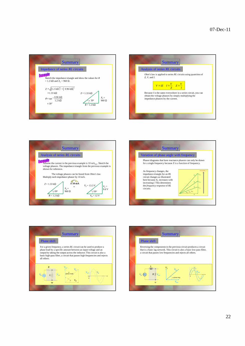
Impedance of series RL circuits
R = 1.2 kΩ
XL = 960 Ω
Sketch the impedance triangle and show the values for R= 1.2 kΩ and XL = 960 Ω.
( ) ( )2 21.2 k + 0.96 k
1.33 k
Z = Ω Ω
= Ω
1 0.96 ktan
1.2 k39
θ − Ω=Ω
= °
Z = 1.33 kΩ
39oθ
Summary
Analysis of series RL circuits
Ohm’s law is applied to series RL circuits using quantities of Z, V, and I.
V V
V IZ I ZZ I
= = =
Because I is the same everywhere in a series circuit, you can obtain the voltage phasors by simply multiplying the impedance phasors by the current.
Summary
Analysis of series RL circuits
Assume the current in the previous example is 10 mArms. Sketch the voltage phasors. The impedance triangle from the previous example is shown for reference.
VR = 12 V
VL = 9.6 V
The voltage phasors can be found from Ohm’s law. Multiply each impedance phasor by 10 mA.
x 10 mA=
R = 1.2 kΩ
XL = 960 Ω
Z = 1.33 kΩ
39o
VS = 13.3 V
39oθθ
Summary
Variation of phase angle with frequency
Phasor diagrams that have reactance phasors can only be drawn for a single frequency because X is a function of frequency.
As frequency changes, the impedance triangle for an RLcircuit changes as illustrated here because XL increases with increasing f. This determines the frequency response of RLcircuits.
θ
XL3
Increasing f
Z1
Z2
Z3
321
XL2
XL1
R
θ θ
θ
(phase lead)
φ
φ
Summary
Phase shift
R
VR
Vout
L VoutVin
Vin
Vout Vin
For a given frequency, a series RL circuit can be used to produce a phase lead by a specific amount between an input voltage and an output by taking the output across the inductor. This circuit is also a basic high-pass filter, a circuit that passes high frequencies and rejects all others.
φ (phase lag)φ
Summary
R
VL
Vout
L
VoutVin
VinVout
Vin
Reversing the components in the previous circuit produces a circuit that is a basic lag network. This circuit is also a basic low-pass filter, a circuit that passes low frequencies and rejects all others.
Phase shift
07-Dec-11
23
Summary
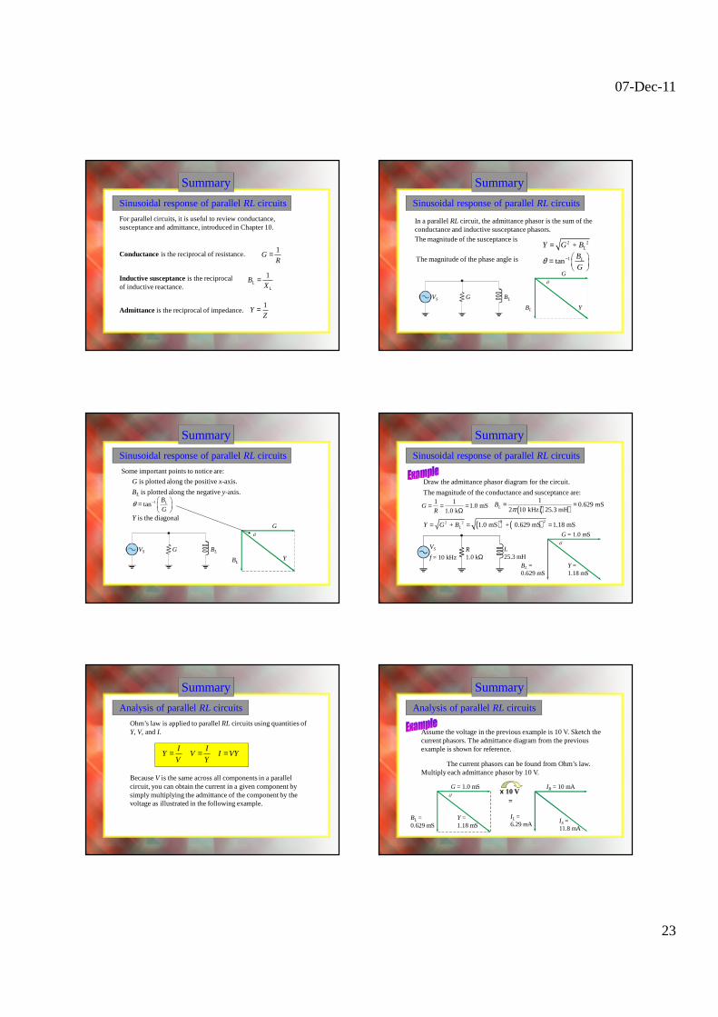
Sinusoidal response of parallel RL circuits
For parallel circuits, it is useful to review conductance, susceptance and admittance, introduced in Chapter 10.
Conductance is the reciprocal of resistance. 1
GR
=
Admittance is the reciprocal of impedance.
Inductive susceptance is the reciprocal of inductive reactance.
1L
L
BX
=
1Y
Z=
Summary
Sinusoidal response of parallel RL circuits
VS G BL
Y
G
BL
In a parallel RL circuit, the admittance phasor is the sum of the conductance and inductive susceptance phasors.The magnitude of the susceptance is 2 2 + LY G B=
The magnitude of the phase angle is 1tan LB
Gθ − =
Summary
Sinusoidal response of parallel RL circuits
Y
G
BL
G is plotted along the positive x-axis.
BL is plotted along the negative y-axis. 1tan LB
Gθ − =
Y is the diagonal
VS G BL
Some important points to notice are:
Summary
Sinusoidal response of parallel RL circuits
VS L25.3 mH
Y = 1.18 mS
G = 1.0 mS
BL = 0.629 mS
Draw the admittance phasor diagram for the circuit.
f = 10 kHzR1.0 kΩ
1 11.0 mS
1.0 kG
R= = =
Ω ( ) ( )1
0.629 mS2 10 kHz 25.3 mHLBπ
= =
The magnitude of the conductance and susceptance are:
( ) ( )2 22 2 + 1.0 mS + 0.629 mS 1.18 mSLY G B= = =
Summary
Analysis of parallel RL circuits
Ohm’s law is applied to parallel RL circuits using quantities of Y, V, and I.
I I
Y V I VYV Y
= = =
Because V is the same across all components in a parallel circuit, you can obtain the current in a given component by simply multiplying the admittance of the component by the voltage as illustrated in the following example.
Summary
Analysis of parallel RL circuits
Assume the voltage in the previous example is 10 V. Sketch the current phasors. The admittance diagram from the previous example is shown for reference.
The current phasors can be found from Ohm’s law. Multiply each admittance phasor by 10 V.
x 10 V=
IR = 10 mA
IL = 6.29 mA IS =
11.8 mA
Y = 1.18 mS
G = 1.0 mS
BL = 0.629 mS
07-Dec-11
24
Summary
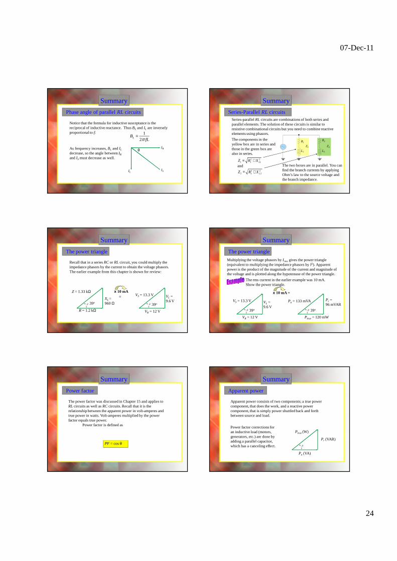
Phase angle of parallel RL circuits
Notice that the formula for inductive susceptance is the reciprocal of inductive reactance. Thus BL and IL are inversely proportional to f: 1
2LBfLπ
=
IR
ILIS
θAs frequency increases, BL and IL
decrease, so the angle between IR
and IS must decrease as well.
Summary
Series-Parallel RL circuitsSeries-parallel RL circuits are combinations of both series and parallel elements. The solution of these circuits is similar to resistive combinational circuits but you need to combine reactive elements using phasors.
The components in the yellow box are in series and those in the green box are also in series.
R1
L1
R2
L2
Z1 Z2
The two boxes are in parallel. You can find the branch currents by applying Ohm’s law to the source voltage and the branch impedance.
and
2 21 1 1LZ R X= +
2 22 2 2LZ R X= +
Summary
The power triangle
x 10 mA=
Recall that in a series RC or RL circuit, you could multiply the impedance phasors by the current to obtain the voltage phasors. The earlier example from this chapter is shown for review:
R = 1.2 kΩ
XL = 960 Ω
Z = 1.33 kΩ
39o
VR = 12 V
VL = 9.6 V
VS = 13.3 V
39o
Summary
Multiplying the voltage phasors by Irms gives the power triangle (equivalent to multiplying the impedance phasors by I2). Apparent power is the product of the magnitude of the current and magnitude of the voltage and is plotted along the hypotenuse of the power triangle.
The rms current in the earlier example was 10 mA. Show the power triangle.
x 10 mA =
Ptrue = 120 mW
Pr = 96 mVAR
The power triangle
39o
Pa = 133 mVA
VR = 12 V
VL = 9.6 V
VS = 13.3 V
39o
Summary
Power factor
The power factor was discussed in Chapter 15 and applies to RL circuits as well as RC circuits. Recall that it is the relationship between the apparent power in volt-amperes and true power in watts. Volt-amperes multiplied by the power factor equals true power.
Power factor is defined as
PF = cos θ
Summary
Apparent power
Apparent power consists of two components; a true power component, that does the work, and a reactive power component, that is simply power shuttled back and forth between source and load.
Ptrue (W)
Pr (VAR)
Pa (VA)
Power factor corrections for an inductive load (motors, generators, etc.) are done by adding a parallel capacitor, which has a canceling effect.
07-Dec-11
25
SummaryFrequency Response of RL Circuits
Series RL circuits have a frequency response similar to series RCcircuits. In the case of the low-pass response shown here, the output is taken across the resistor.
100 Ω10 mH
10 V dc
VoutVin
10 V dc
0
10 V dc
0
Plotting the response:
100 Ωƒ = 1 kHz
8.46 V rms10 V rms 10 mH
100 Ω10 mH
ƒ = 10 kHz
1.57 V rms
10 V rms
100 Ω10 mH
ƒ = 20 kHz
0.79 V rms
10 V rms
Vout (V)
9.98
8.46
1.570.79
0.1 1 10 20 100f (kHz)
9
8
7
6
5
4
3
2
1
SummaryFrequency Response of RL Circuits
Reversing the position of the R and L components, produces the high-pass response. The output is taken across the inductor.
Vin
10 V dc
0
Vout
0 V dc10 V dc100 Ω
10 mH
Plotting the response:
Vout (V)
f (kHz)
9.87
5.32
0.6300.01 0.1 1
10
98
7
6
5
4
3
21
10
ƒ = 100 Hz0.63 V rms
10 V rms 10010 mHƒ = 1 kHz
5.32 V rms10 V rms
100 Ω10 mH
ƒ = 10 kHz
9.87 V rms10 V rms
100 Ω10 mH
Inductive susceptance (BL)
The ability of an inductor to permit current; the reciprocal of inductive reactance. The unit is the siemens (S).
Key Terms Quiz
1. If the frequency is increased in a series RL circuit, the phase angle will
a. increase
b. decrease
c. be unchanged
Quiz
2. If you multiply each of the impedance phasors in a series RL circuit by the current, the result is the
a. voltage phasors
b. power phasors
c. admittance phasors
d. none of the above
Quiz
3. For the circuit shown, the output voltage
a. is in phase with the input voltage
b. leads the input voltage
c. lags the input voltage
d. none of the above Vin Vout
07-Dec-11
26
Quiz
4. In a series RL circuit, the phase angle can be found from the equation
a.
b.
c. both of the above are correct
d. none of the above is correct
1tan LX
Rθ − =
1tan L
R
V
Vθ −
=
Quiz
5. In a series RL circuit, if the inductive reactance is equal to the resistance, the source current will lag the source voltage by
a. 0o
b. 30o
c. 45o
d. 90o
Quiz
6. Susceptance is the reciprocal of
a. resistance
b. reactance
c. admittance
d. impedance
Quiz
7. In a parallel RL circuit, the magnitude of the admittance can be expressed as
a.
b.
c. Y = G + BL
d. 2 2 + LY G B=
2 2 LY G B= −
11 1
L
Y
G B
=+
Quiz
8. If you increase the frequency in a parallel RL circuit,