530 IEE E TRANSACTI ONS ON COMPONENT S, P ACKAGING, AND MANUF ACT URI NG TECHNOLOGY—P AR T A, VOL. 20, NO. 4, DECEMB ER 199 7 Finite Element Simulation of the Temperature Cycling Tests Cemal Basaran and Rumpa Chandaroy Abstract—Temperature cycling tests are commonly used in the semi condu ctor industr y to dete rmin e the number of cycl es to failure and to predict reliability of the solder joints in the surface mount technology packages. In this paper, the thermomechanical fatigue of Pb40/Sn60 solder joint in a leadless ceramic chip carrier package is studied and [16] temperature cycling test is simulated by usi ng a fini te el eme nt pr ocedur e wit h the dis tur bed sta te concept (DSC) constitutive models. The progress of disturbance (dama ge) and the energy dissipat ed in the solder joint duri ng thermal cycling are predicted. It is shown that the disturbance criterion used follows a similar path as the energy dissipation in the system. Moreover, the comparisons between the test data and the finite element analysis show that a finite element procedure using the DSC material models can be instrumental in reliability anal ys is and to pr edic t the number of cycl es to fail ur e of a solder joint. Furth ermor e, the analysis gives a good picture ofthe progress of the failure mechanism and the disturbance in the solder joint . Index T erms—Damage mechanics, electronic packaging, finite element analy sis, solde r joint . I. INTRODUCTION R ELI ABI LITY of sol der joi nts in sur fac e mou nt tec h- nol ogy (SMT) microele ctr oni cs pac kag ing is a gre at concer n to pac kag ing design eng ine ers . Dur ing its des ign life, the sol der joi nt in SMT pac kag e exp eri enc es a wid e range of temper atu re var iat ions, whi ch may var y bet wee n 40 C and 150 C, or ma y eve n be wider in aut omat ive applications. Although a variety of mechanisms (e.g. vibration, cor rosion, dif fus ion , mec han ica l shock, etc .) may lea d to solder joi nt failure, the pri mar y mechanisms are thermal stress and low-c ycle stra in-c ontr olle d fati gue, [23]. Fatig ue failure of ma ter ial s and str uct ure s is due to the ini tia tio n and propagation of fatigue fractures under the action of the repeated removal and reversal of the applied load. If this load is produced by thermally induced stresses than thermal fatigue occurs, [40]. Fati gue damage is usual ly the result of stress concentrations caused by dislocation pileups due to inelastic to- and -fro sli pmo tion of lat tic e def ect s and due to sli din g between grains at the boundaries. The dislocation slip motion is caused by mechanical stresses, [8]. The conne cted comp onents have dif feren t coef ficie nts ofther mal expan sion (CTE) and dif fere nt mate rial prop erti es. Because of the CTE mismatch, different elongation and con- trac tion s take place in the comp onent s. These compone nts Manuscript received January 1996; revised October 28, 1996. This workwas sponsored by the Department of Defense Office of Naval Research Young Investigator Award program. The authors are with the Department of Civil, Structural, and Environmental Engineering, State University of New York, Buffalo, NY 14260 USA. Publisher Item Identifier S 1070-9886(97)09198-1. experience relative motions during which shear and bending stresses are induced on the solder joint assembly. As a result of the temperature cycles, the solder joint experiences elastic, plastic and viscoplastic (time dependent, creep or relaxation) deformations. Eventually these deformations cause the accu- mula tion of micr ocrac king and dama ge in the solder join t. When the damage energy exceeds the crack initiation energy of the material, the initiation of cracks becomes inevitable. Thermal cycling is an accepted experimental procedure for condu cting surface mount technolo gy packa ge solder join t reli abil ity test ing under accel erat ed condi tion s, [6]. These experiments are very commonly used in the microelectronics ind ust ry. The onl y inf ormati on the se tests pro vid e is the number of temperature cycles that are needed to fail a solder joint. The failure of the solder joint does not, however, give any information concerning what and where the problem is or where the damage initiated in the solder joint. Furthermore, the results of these experiments do not provide information on the stress distribution and microcracking zones in the joint. Hence thes e test s are limited in thei r usef ulne ss to under stand the thermomechanical damage behavior of the solder joint. There is, therefore, a need for a numerical analysis procedure, such as finite element method, which contains a unified constitutive models for materials in order to supplement the temperature cycl ing test s. This nonli near nume rica l anal ysis proce dure would be instrumental in studying the thermomechanical dam- age mechanics of solder joints. A number of researchers have proposed constitutive models to study damage mechanics of solder alloys. Some of them are [1], [6][8], [14], [15], [19], [20], [22], [24], [26], [28], [30], [32][34], [36], [38], [39], [41], [42], [46], and others. “A common shortfall of these models is that most are empirical in nat ure and do not include the mic ros tru ctural beh avior that occurs in Sn/Pb solder during thermomechanical fatigue,” Frear et al. [14]. It should be pointed out that most of the proposed constitutive models in the literature are verified by backpredicting the same test data that was used to obtain the mate rial parame ters. This latter approach of curv e fitti ng is not a goo d met hod to prove that the propos ed model is a robust constitutive model based on the rules of the theory ofplasticity [11]. Moreover, backpredicting the test data that was used to obtain the material constants usually yields an excellent match but when a different stress path or just a different test is backpredicted the results are usually less than satisfactory. II. THE DISTURBEDSTATE CONCEPT(DSC) The idea for this theory was originally proposed by Desai [1974] in order to charac te ri ze the behavior of the over 10709886/97$10.00 1997 IEEE
530 IEEE TRANSACTIONS ON COMPONENTS PACKAGING AND MANUFACTURING TECHNOLOGYmdashPART A VOL 20 NO 4 DECEMBER 1997
Finite Element Simulation of theTemperature Cycling Tests
Cemal Basaran and Rumpa Chandaroy
AbstractmdashTemperature cycling tests are commonly used in thesemiconductor industry to determine the number of cycles tofailure and to predict reliability of the solder joints in the surfacemount technology packages In this paper the thermomechanicalfatigue of Pb40Sn60 solder joint in a leadless ceramic chip carrierpackage is studied and [16] temperature cycling test is simulatedby using a finite element procedure with the disturbed stateconcept (DSC) constitutive models The progress of disturbance(damage) and the energy dissipated in the solder joint duringthermal cycling are predicted It is shown that the disturbancecriterion used follows a similar path as the energy dissipation inthe system Moreover the comparisons between the test data andthe finite element analysis show that a finite element procedureusing the DSC material models can be instrumental in reliability
analysis and to predict the number of cycles to failure of asolder joint Furthermore the analysis gives a good picture of the progress of the failure mechanism and the disturbance in thesolder joint
Index Termsmdash Damage mechanics electronic packaging finiteelement analysis solder joint
I INTRODUCTION
RELIABILITY of solder joints in surface mount tech-
nology (SMT) microelectronics packaging is a great
concern to packaging design engineers During its design
life the solder joint in SMT package experiences a wide
range of temperature variations which may vary between
40 C and 150 C or may even be wider in automativeapplications Although a variety of mechanisms (eg vibration
corrosion diffusion mechanical shock etc) may lead to
solder joint failure the primary mechanisms are thermal
stress and low-cycle strain-controlled fatigue [23] Fatigue
failure of materials and structures is due to the initiation
and propagation of fatigue fractures under the action of the
repeated removal and reversal of the applied load If this load
is produced by thermally induced stresses than thermal fatigue
occurs [40] Fatigue damage is usually the result of stress
concentrations caused by dislocation pileups due to inelastic
to-and-fro slipmotion of lattice defects and due to sliding
between grains at the boundaries The dislocation slip motion
is caused by mechanical stresses [8]
The connected components have different coefficients of
thermal expansion (CTE) and different material properties
Because of the CTE mismatch different elongation and con-
tractions take place in the components These components
Manuscript received January 1996 revised October 28 1996 This work was sponsored by the Department of Defense Office of Naval Research YoungInvestigator Award program
The authors are with the Department of Civil Structural and EnvironmentalEngineering State University of New York Buffalo NY 14260 USA
Publisher Item Identifier S 1070-9886(97)09198-1
experience relative motions during which shear and bending
stresses are induced on the solder joint assembly As a result
of the temperature cycles the solder joint experiences elastic
plastic and viscoplastic (time dependent creep or relaxation)
deformations Eventually these deformations cause the accu-
mulation of microcracking and damage in the solder joint
When the damage energy exceeds the crack initiation energy
of the material the initiation of cracks becomes inevitable
Thermal cycling is an accepted experimental procedure for
conducting surface mount technology package solder joint
reliability testing under accelerated conditions [6] These
experiments are very commonly used in the microelectronics
industry The only information these tests provide is thenumber of temperature cycles that are needed to fail a solder
joint The failure of the solder joint does not however give
any information concerning what and where the problem is or
where the damage initiated in the solder joint Furthermore the
results of these experiments do not provide information on the
stress distribution and microcracking zones in the joint Hence
these tests are limited in their usefulness to understand the
thermomechanical damage behavior of the solder joint There
is therefore a need for a numerical analysis procedure such
as finite element method which contains a unified constitutive
models for materials in order to supplement the temperature
cycling tests This nonlinear numerical analysis procedure
would be instrumental in studying the thermomechanical dam-age mechanics of solder joints
A number of researchers have proposed constitutive models
to study damage mechanics of solder alloys Some of them
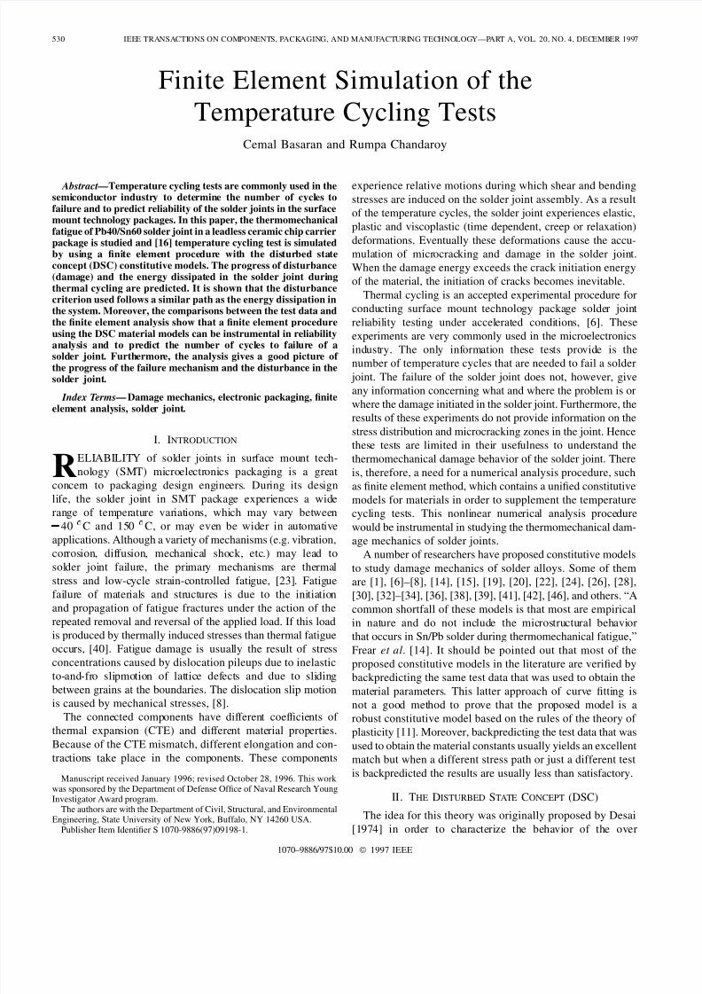
BASARAN AND CHANDAROY FINITE ELEMENT SIMULATION OF THE TEMPERATURE CYCLING TESTS 535
Fig 10 Damage distribution in the solder joint at the end of the first thermalcycle
as well as dimensions of the joint and the loading history
But the finite element analysis results are particularly sensitive
to the elastic modulus value The finite element method is a
numerical analysis procedure for solving partial differential
equations The solution converges to the exact solution of
the partial differential equation as the discretization is refined
for the strain hardening region of the stress-strain diagram
In the strain-softening region it is well known that finite
element method experiences mesh sensitivity In DSC models
mesh sensitivity is dealt with nonlocal continuum based DSC
average strain method where the strain is averaged over
a characteristic length It has been demonstrated by manyresearchers such as [3] [10] [45] that FEM can successfully
be used to solve boundary value problems if accurate material
constants and proper constitutive models are used
It is well known that an exact analysis with strict adherence
to the constitutive relations of linear elasticity yields a sin-
gularity at the intersection of the free edge with an interface
of two dissimilar materials [43] When the material model is
inelastic singularity does not occur because of the condition
of consistency of the theory of plasticity [11] The condition
of consistency requires that when the state of stress is outside
the yield surface as in the case of a singularity it must be
brought back to the yield surface with a return strategy Further
discussion on this subject is given in [2]Another problem faced in obtaining the material constants
is that most of the testing is performed on bulk solder The
size of bulk sample is large relative to the solder joint
Hall and Sherry [17] report that ldquoThe specimen size versus
the microstructure size ratio effects may be importantrdquo in
determining the mechanical behavior Bonda and Noyan [4]
have shown that the material properties of a microscale joint
in an actual semiconductor device is different than the large
bulk specimen of the solder alloy
It should be emphasized that the results obtained here are
strictly valid for the solder configuration used in this study
Solder joint dimensions height in particular and the solder
material affect the reliability and the thermal fatigue life
Discussion of this topic is outside the scope of this paper
VII CONCLUSION
In this paper a finite element procedure based on the
Disturbed State Concept material models is proposed for
the thermomechanical reliability analysis of solder joints insurface mount technology packaging It has been shown that
the thermomechanical behavior of microelectronics packaging
solder joints can be predicted by proper constitutive models
Using the finite element procedure proposed herein acceler-
ated thermal cycling tests can be simulated and the proposed
numerical procedure can used in conjunction with the tests
The Disturbed State Concept allows characterization of the
material behavior to be represented in terms of two reference
states of the material namely the relative intact and the fully
adjusted states This feature makes DSC particularly powerful
to characterize behavior of two phase materials such as PbSn
alloys Furthermore the Disturbed State Concept allows us to
have different stresses and strains in both the intact part and the
fully adjusted parts of the material Because of the differential
strain in the material we are able to account for the relative
motions in the material Considering the relative motion within
the material provides us with a more accurate characterization
of the energy of the material than the conventional continuum
damage mechanics models do
The results of this research can be instrumental in making
predictions of reliability of interconnections under thermal
cycling stresses Material properties used in this study areobtained from experimental results published in the literature
The experiments backpredicted were not used to obtain mate-
rial constants Most of the time a complete description of thetest setup and conditions in which the tests were run are not
available Therefore when the material constants are obtained
certain assumptions are made The accurate determination of
the material constants is crucial to the analysis since the finite
element results are sensitive to the material parameters
ACKNOWLEDGMENT
The authors would like to thank C S Desai T Kundu and
J Prince University of Arizona Tucson for their help
REFERENCES
[1] D Barker Vodzak A Dasgupta and M Pecht ldquoCombined vibra-tional and thermal solder joint fatiguemdashA generalized strain versus lifeapproachrdquo J Electron Packag vol 112 pp 129134 1990
[2] C Basaran and C S Desai Finite Element Thermomechanical Analysisof Electronic Packaging Problems Using the Disturbed State Constitutive
Models Report to NSF Dept Civil Engineering and EngineeringMechanics Univ of Arizona Tucson 1994
[3] K J Bathe Finite Element Procedures Engelwood Cliffs NJPrentice-Hall 1996
[4] N R Bonda and I C Noyan ldquoEffect of specimen size in predictingthe mechanical properties of PbSn solder alloysrdquo IEEE Trans CompPackag Manufact Technol vol 19 1996
[5] J Chia and C S Desai Constitutive Modeling of Thermomechanical Response of Materials in Semiconductor Devices With Emphasis on
Interface Behavior Report to NSF Depart Civil Engineering andEngineering Mechanics University of Arizona 1994
536 IEEE TRANSACTIONS ON COMPONENTS PACKAGING AND MANUFACTURING TECHNOLOGYmdashPART A VOL 20 NO 4 DECEMBER 1997
[6] J-P Clech and J A Augis ldquoEngineering analysis of thermal cyclingaccelerated test for surface-mount attachment reliability evaluationrdquo inProc VII Ann Electron Packag Conf Boston MA Nov 1987 vol1 pp 385411
[7] R Darveaux Y Edward I Turlik and K I Murty ldquoMechanical char-acteristics of IN and Pb55Sn solders in a thinfilm multichip packagerdquoin Proc Mater Res Symp vol 203 pp 443449 1991
[8] A Dasgupta C Oyan D Barker and M Pecht ldquoSolder creep-fatigueanalysis by an energy-partitioning approachrdquo Trans ASME J ElectronPackag vol 114 1992
[9] C S Desai ldquoA consistent finite element technique for work-softeningbehaviorrdquo in Proc Int Conf Comp Meth Nonlinear Mech J T Odenet al Eds Austin TX Univ of Texas Press 1974
[10] Elementary Finite Element Method Englewood Cliffs NJPrentice-Hall 1979
[11] C S Desai and H Siriwardane Constitutive Laws for Engineering Materials With Emphasis on Geologic Materials Englewood CliffsNJ Prentice-Hall 1984
[12] C S Desai ldquoConstitutive modeling using the disturbed state as mi-crostructure self-adjustment conceptrdquo in Continuum Models for Ma-terials with Microstructure H B Muhlhaus Ed New York Wiley1996
[13] C S Desai C Basaran and Z Wu ldquoNumerical algorithms and meshsensitivity in disturbed state concept modelsrdquo Int J Numer Meth vol40 pp 30593083 1997
[14] D R Frear S N Burchett and M M Rashid ldquoA microstructurallybased model of solder under conditions of thermomechanical fatiguerdquoTrans ASME Adv Electron Packag vol EEP-10 no 1 1995
[15] Q Guo E C Cutiongco L M Keer and M E Fine ldquoThermome-chanical fatigue life prediction of 63Sn37Pb solderrdquo Trans ASME J
Electron Packag vol 114 pp 145151 June 1992[16] P Hall ldquoForces moments and displacements during thermal chamber
cycling of leadless ceramic chip carriers soldered to printed boardsrdquo IEEE Trans Comp Hybrids Manufact Technol vol CHMT-7 pp314327 1984
[17] P M Hall and W M Sherry ldquoMaterials structures and mechanicsof solder-joints for surface-mount microelectronics technologyrdquo inProc Lectures 3rd Int Conf Techniques de Connexion en Electronique Welding Society Fellbach Dusseldorf Germany Feb 1986 pp 1820
[18] C A Harper Handbook of Materials and Processes for ElectronicsNew York McGraw-Hill 1970
[19] J H Huang J Y Pei Y Y Qian and Y H Jiang ldquoLife predictionsof SMT solder joints under thermal cyclingrdquo Soldering Surface Mount Technol 1994 vol 16 pp 3150
[20] H Ishikawa and K Sasaki ldquoConstitutive model for 60Sn-40Pb sol-
der under cycling loadingrdquo Adv Electron Packag in Proc Joint ASMEJSME Conf Electron Packag W T Chen and H Abe Eds1992 vol 1 pp 401408
[21] L M Kachanov Introduction of Continuum Damage Mechanics Am-sterdam The Netherlands Martinus Nijhoff 1986
[22] S Knecht and L R Fox ldquoConstitutive relation and creep-fatiguelife model for eutectic tin-lead solderrdquo IEEE Trans Comp Hybrids
Manufact Technol vol 13 pp 424433 June 1990[23] J H Lau D W Rice and D A Avery ldquoElasto plastic analysis of
surface mount solder jointsrdquo IEEE Trans Comp Hybrids ManufactTechnol vol CHMT-10 Sept 1987
[24] J Lau and S Erasmus ldquoReliability of fine pitch plastic quad flat pack leads and solder joints under bending twisting and thermal conditionsrdquo
J Electron Packag vol 115 pp 322328 1993[25] H B Muhlhaus ldquoA thermodynamic criteria for damagerdquo in Proc 8th
Int Conf Int Assoc Comput Methods Adv Geomech WV May 1994pp 2228
[26] Y Oshida and P Chen ldquoHigh and low-cycle fatigue damage evaluationof multilayer thin film structurerdquo Trans ASME J Electron Packagvol 113 Mar 1991
[27] D R J Owen and E Hinton Finite Elements in Plasticity SwanseaUK Pineridge
[28] T Pan ldquoThermal cycling induced plastic deformation in solder jointsPart III Strain-energy based fatigue life model and effects of ramp rateand hold timerdquo in Proc ASME Winter Ann Meet Atlanta GA Dec1991 pp 16
[29] Y H Pao K L Chen and A Y Kuo ldquoA nonlinear and time dependentfinite element analysis of solder joints in surface mounted componentsunder thermal cyclingrdquo in Proc Mat Res Soc Symp 1991 vol226
[30] Y H Pao R Govila S Badgley and E Jih ldquoAn experimental andfinite element study of thermal fatigue fracture of PbSn solder jointsrdquo
J Electron Packag vol 115 pp 18 1993
[31] E D Riemer ldquoPrediction of temperature cycling life for SMT solder joints on TCE-mismatched substratesrdquo in Proc Electron Comp 1990pp 418423
[32] R G Ross L C Wen G R Mon and E Jetter ldquoSolder creep-fatigueinteractions with flexible leaded partsrdquo J Electron Packag vol 114pp 185192 1992
[33] J Sauber and Seyyedi ldquoPredicting thermal fatigue lifetimes for SMTsolder jointsrdquo J Electron Packag vol 114 pp 472476 1992
[34] C G Schmidt ldquoA simple model for fatigue of leadless ceramic chipcarrier solder attachmentsrdquo J Electron Manufact vol 2 pp 3136
1992[35] W M Sherry J S Erich M K Bartschat and F B Prinz ldquoAnalyticaland experimental analysis of LCCC solder joint fatigue liferdquo in Proc
Electron Comp Conf 1985 pp 8190[36] A Skipor S Harren and J Botsis ldquoConstitutive characterization of
6337 SnPb eutectic solder using the bodner-partom unified creep-plasticity modelrdquo ASME Adv Electron Packag pp 661672 1992
[37] H D Solomon ldquoLow cycle fatigue of 6040 solder plastic strain limitedvs displacement limited testingrdquo Electron Packag Mater Processespp 2947 1989
[38] H D Solomon and E D Tolksdorf ldquoEnergy approach to the fatigue of 6040 solder Part IImdashInfluence of hold time and asymmetric loadingrdquo
J Electron Packag vol 118 pp 6771 1996[39] R Subrahmanyan J R Wilcox and C Li ldquoA damage integral approach
to thermal fatigue of solder jointsrdquo IEEE Trans Comp Hybrids Manufact Technol vol 12 Dec 1989
[40] E Suhir ldquoThermal stress failures in microelectronic components-reviewand extensionrdquo in Advances in Thermal Modeling of Electronic Com-
ponents and Systems A Bar-Cohen and A Kraus Eds 1989 ch 5vol 1 pp 337412
[41] J K Tien B C Hendrix and A I Attarwala ldquoUnderstanding thecyclic mechanical behavior of leadtin solderrdquo Trans ASME J ElectronPackag vol 113 June 1991
[42] S Verma A Dasgupta and D Barker ldquoA Numerical study of fatiguelife of J-leaded solder joints using the energy partitioning approachrdquo J
Electron Packag vol 115 pp 416423 1993[43] W L Yin ldquoThermal stresses and free-edge effects in laminated beams
A variational approach using stress functionsrdquo J Electron Packagvol 113 pp 6875 1991
[44] O C Zienkiewicz The Finite Element Method New York McGrawHill 1986
[45] O C Zienkiewicz and I C Comeau ldquoViscoplasticity-plasticity andcreep in elastic solids-a unified approachrdquo Int J Numer Meth Engvol 8 pp 821845 1974
[46] A Zubelewicz Q Guo E C Cutiongco M E Fine and L M Keer
ldquoMicromechanical method to predict fatigue life of solderrdquo J ElectronPackag vol 112 1990
Cemal Basaran received the MS degree from theMassachusetts Institute of Technology Cambridgeand the PhD degree from the University of Ari-zona Tucson
He is an Assistant Professor in the Department of Civil Structural and Environmental EngineeringState University of New York Buffalo His re-search interest is in experimental and computationalreliability study of interconnects and interfaces inelectronic packaging under combined dynamic andthermal loading
Dr Basaran received the DoD ONR Young Investigator Award for his
research on damage mechanics of power electronic packaging interconnectsand interfaces in 1997
Rumpa Chandaroy received the MS degree fromthe State University of New York Buffalo and iscurrently pursuing the PhD degree in thermome-chanical response of solder joints under concurrentdynamic and thermal cycling loading at the De-partment of Civil Structural and EnvironmentalEngineering
Ms Chandaroy received the India National Schol-arship