Basement excavation works in KL limestone formation for underground connection to existing MRT station at AEON Maluri, Malaysia Yean Chin Tan 1 , K.S. Koo 2 , F.W. Chee 3 and C.-G. Tan 4 1,2,3 & 4 G&P Geotechnics Sdn Bhd, 39-5, Jalan Tasik Selatan 3, Bandar Tasik Selatan 57000 Kuala Lumpur, Malaysia. ABSTRACT This paper describes the design and construction of retaining wall system for basement structure next to the existing MRT structure in limestone formation. The proposed basement aims to connect two underground structure i.e. Maluri MRT Station and AEON Maluri shopping mall for ease of public access. Karstic formation condition poses a challenge to the design and construction of excavation works next to completed Maluri MRT station. The Maluri MRT station had been completed and open for public in year 2017. Therefore, Malaysia Railway Act 1991 is applicable to the basement excavation work within the Railway Protection Zone (RPZ). Permit to work within RPZ is necessary to be obtained from SPAD (Malaysia Land Transport Authority) with technical evaluation from Mass Rapid Transit Corporation (MRTC). The objective of RPZ is to protect asset and public interest from any potential risk or damages caused by adjacent construction work. Other than proper design and construction, numerous types of instrumentations e.g. standpipe, settlement marker, inclinometer and recharge well have been proposed and installed in view of close proximity between the basement excavation and MRT structure. Closely monitoring have been performed with daily recording upon commencement of excavation works. Validation of the retaining wall performance had been carried out by comparing the monitoring result against design prediction. Retaining wall performance back analysis was carried out to compare the design parameters and actual performance from monitoring results. The findings indicated that the sub-soil stiffness is up to 3000N for averagely SPT’N value of 3 and the limestone stiffness for pile embedded in rock ranges from 1 GPa to 3 GPa. Keywords: Earth retaining structure, limestone formation, basement excavation, underground connection 1 INTRODUCTION This paper shares the experience on design and construction of earth retaining system for basement structure at AEON Maluri, Kuala Lumpur, Malaysia, which is located near to an existing MRT station, namely Maluri MRT station. The site originally was an open carpark and being proposed to develop into two level basement structure of 12m retained height with contiguous bored pile wall as earth retaining system. The intended purpose for the proposed basement is aiming for underground connection between two underground structures i.e. Maluri MRT Station and AEON Maluri shopping mall for direct public access. The Maluri MRT station was completed and in operation since year 2017 before commencement of proposed AEON Maluri basement structure, thus, Malaysia Railway Act 1991 is enforced and applicable to the proposed basement excavation works within the Railway Protection Zone (RPZ) as defined in Act. In accordance with the Railway Act 1991, permit to work within the RPZ is necessary to be obtained from SPAD (Malaysia Land Transport Authority) with technical evaluation from Mass Rapid Transit Corporation (MRTC). Figure 1 shows the overview of excavation works for the project. Fig. 1. Overview of Excavation Works 2 GROUND CONDITIONS The AEON Maluri shopping mall is located at Jalan Cheras, Kuala Lumpur, Malaysia, which is underlain by Kuala Lumpur Limestone formation. The nature of Kuala Lumpur Limestone with karstic features included the pinnacle zone, overhangs, floaters, cavities, solution channels and collapsed weak soil just above bedrock are potential hazard for deep excavation work. The proposed site investigation program confirmed the rock head at 7m to 20m below ground and overlaying by Alluvial deposits. The Alluvial deposits are generally dominated by silty sand. The Standard Penetration Test (SPT) ‘N’ value of subsoil is generally less than 4 for
Transcript
Basement excavation works in KL limestone formation for underground connection to existing MRT station at AEON Maluri, Malaysia
Yean Chin Tan1, K.S. Koo2, F.W. Chee3 and C.-G. Tan4
1,2,3 & 4 G&P Geotechnics Sdn Bhd, 39-5, Jalan Tasik Selatan 3, Bandar Tasik Selatan 57000 Kuala Lumpur, Malaysia.
ABSTRACT This paper describes the design and construction of retaining wall system for basement structure next to the
existing MRT structure in limestone formation. The proposed basement aims to connect two underground structure i.e. Maluri MRT Station and AEON Maluri shopping mall for ease of public access. Karstic formation condition poses a challenge to the design and construction of excavation works next to completed Maluri MRT station. The Maluri MRT station had been completed and open for public in year 2017. Therefore, Malaysia Railway Act 1991 is applicable to the basement excavation work within the Railway Protection Zone (RPZ). Permit to work within RPZ is necessary to be obtained from SPAD (Malaysia Land Transport Authority) with technical evaluation from Mass Rapid Transit Corporation (MRTC). The objective of RPZ is to protect asset and public interest from any potential risk or damages caused by adjacent construction work. Other than proper design and construction, numerous types of instrumentations e.g. standpipe, settlement marker, inclinometer and recharge well have been proposed and installed in view of close proximity between the basement excavation and MRT structure. Closely monitoring have been performed with daily recording upon commencement of excavation works. Validation of the retaining wall performance had been carried out by comparing the monitoring result against design prediction. Retaining wall performance back analysis was carried out to compare the design parameters and actual performance from monitoring results. The findings indicated that the sub-soil stiffness is up to 3000N for averagely SPT’N value of 3 and the limestone stiffness for pile embedded in rock ranges from 1 GPa to 3 GPa. Keywords: Earth retaining structure, limestone formation, basement excavation, underground connection
1 INTRODUCTION
This paper shares the experience on design and construction of earth retaining system for basement structure at AEON Maluri, Kuala Lumpur, Malaysia, which is located near to an existing MRT station, namely Maluri MRT station. The site originally was an open carpark and being proposed to develop into two level basement structure of 12m retained height with contiguous bored pile wall as earth retaining system. The intended purpose for the proposed basement is aiming for underground connection between two underground structures i.e. Maluri MRT Station and AEON Maluri shopping mall for direct public access.
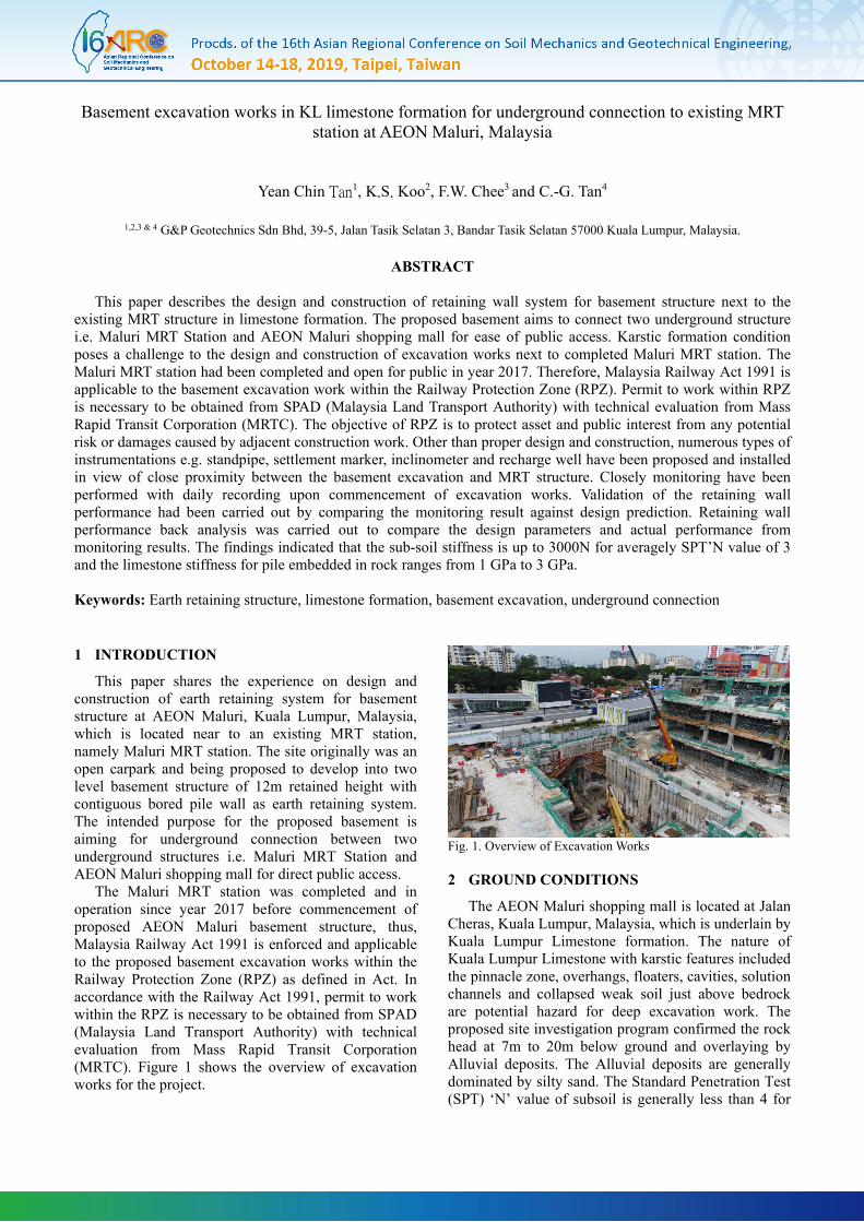
The Maluri MRT station was completed and in operation since year 2017 before commencement of proposed AEON Maluri basement structure, thus, Malaysia Railway Act 1991 is enforced and applicable to the proposed basement excavation works within the Railway Protection Zone (RPZ) as defined in Act. In accordance with the Railway Act 1991, permit to work within the RPZ is necessary to be obtained from SPAD (Malaysia Land Transport Authority) with technical evaluation from Mass Rapid Transit Corporation (MRTC). Figure 1 shows the overview of excavation works for the project.
Fig. 1. Overview of Excavation Works
2 GROUND CONDITIONS
The AEON Maluri shopping mall is located at Jalan Cheras, Kuala Lumpur, Malaysia, which is underlain by Kuala Lumpur Limestone formation. The nature of Kuala Lumpur Limestone with karstic features included the pinnacle zone, overhangs, floaters, cavities, solution channels and collapsed weak soil just above bedrock are potential hazard for deep excavation work. The proposed site investigation program confirmed the rock head at 7m to 20m below ground and overlaying by Alluvial deposits. The Alluvial deposits are generally dominated by silty sand. The Standard Penetration Test (SPT) ‘N’ value of subsoil is generally less than 4 for
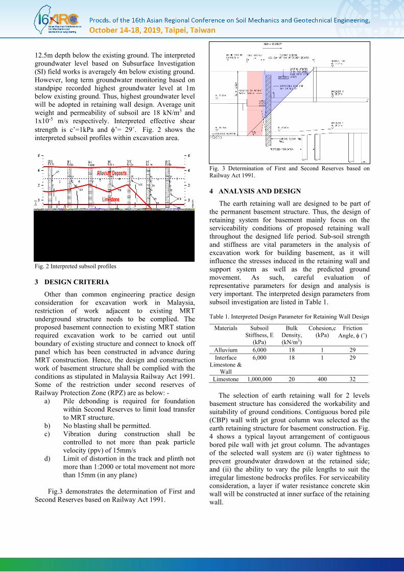
12.5m depth below the existing ground. The interpreted groundwater level based on Subsurface Investigation (SI) field works is averagely 4m below existing ground. However, long term groundwater monitoring based on standpipe recorded highest groundwater level at 1m below existing ground. Thus, highest groundwater level will be adopted in retaining wall design. Average unit weight and permeability of subsoil are 18 kN/m3 and 1x10⁻⁵ m/s respectively. Interpreted effective shear strength is c’=1kPa and φ’= 29˚. Fig. 2 shows the interpreted subsoil profiles within excavation area.
Fig. 2 Interpreted subsoil profiles
3 DESIGN CRITERIA
Other than common engineering practice design consideration for excavation work in Malaysia, restriction of work adjacent to existing MRT underground structure needs to be complied. The proposed basement connection to existing MRT station required excavation work to be carried out until boundary of existing structure and connect to knock off panel which has been constructed in advance during MRT construction. Hence, the design and construction work of basement structure shall be complied with the conditions as stipulated in Malaysia Railway Act 1991. Some of the restriction under second reserves of Railway Protection Zone (RPZ) are as below: -
a) Pile debonding is required for foundation within Second Reserves to limit load transfer to MRT structure.
b) No blasting shall be permitted. c) Vibration during construction shall be
controlled to not more than peak particle velocity (ppv) of 15mm/s
d) Limit of distortion in the track and plinth not more than 1:2000 or total movement not more than 15mm (in any plane)
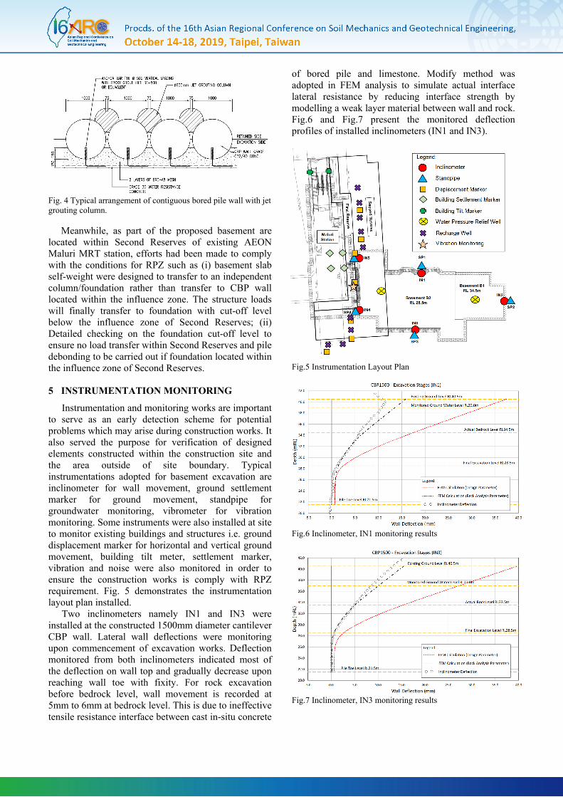
Fig.3 demonstrates the determination of First and
Second Reserves based on Railway Act 1991.
Fig. 3 Determination of First and Second Reserves based on Railway Act 1991.
4 ANALYSIS AND DESIGN
The earth retaining wall are designed to be part of the permanent basement structure. Thus, the design of retaining system for basement mainly focus on the serviceability conditions of proposed retaining wall throughout the designed life period. Sub-soil strength and stiffness are vital parameters in the analysis of excavation work for building basement, as it will influence the stresses induced in the retaining wall and support system as well as the predicted ground movement. As such, careful evaluation of representative parameters for design and analysis is very important. The interpreted design parameters from subsoil investigation are listed in Table 1. Table 1. Interpreted Design Parameter for Retaining Wall Design
Materials Subsoil Stiffness, E
(kPa)
Bulk Density, (kN/m3)
Cohesion,c (kPa)
Friction Angle, φ (˚)
Alluvium 6,000 18 1 29 Interface
Limestone & Wall
6,000 18 1 29
Limestone 1,000,000 20 400 32 The selection of earth retaining wall for 2 levels
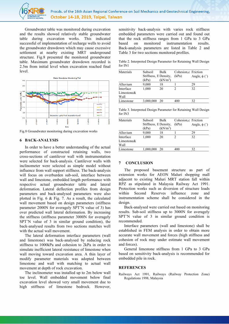
basement structure has considered the workability and suitability of ground conditions. Contiguous bored pile (CBP) wall with jet grout column was selected as the earth retaining structure for basement construction. Fig. 4 shows a typical layout arrangement of contiguous bored pile wall with jet grout column. The advantages of the selected wall system are (i) water tightness to prevent groundwater drawdown at the retained side; and (ii) the ability to vary the pile lengths to suit the irregular limestone bedrocks profiles. For serviceability consideration, a layer if water resistance concrete skin wall will be constructed at inner surface of the retaining wall.
Fig. 4 Typical arrangement of contiguous bored pile wall with jet grouting column.
Meanwhile, as part of the proposed basement are located within Second Reserves of existing AEON Maluri MRT station, efforts had been made to comply with the conditions for RPZ such as (i) basement slab self-weight were designed to transfer to an independent column/foundation rather than transfer to CBP wall located within the influence zone. The structure loads will finally transfer to foundation with cut-off level below the influence zone of Second Reserves; (ii) Detailed checking on the foundation cut-off level to ensure no load transfer within Second Reserves and pile debonding to be carried out if foundation located within the influence zone of Second Reserves.
5 INSTRUMENTATION MONITORING
Instrumentation and monitoring works are important to serve as an early detection scheme for potential problems which may arise during construction works. It also served the purpose for verification of designed elements constructed within the construction site and the area outside of site boundary. Typical instrumentations adopted for basement excavation are inclinometer for wall movement, ground settlement marker for ground movement, standpipe for groundwater monitoring, vibrometer for vibration monitoring. Some instruments were also installed at site to monitor existing buildings and structures i.e. ground displacement marker for horizontal and vertical ground movement, building tilt meter, settlement marker, vibration and noise were also monitored in order to ensure the construction works is comply with RPZ requirement. Fig. 5 demonstrates the instrumentation layout plan installed.
Two inclinometers namely IN1 and IN3 were installed at the constructed 1500mm diameter cantilever CBP wall. Lateral wall deflections were monitoring upon commencement of excavation works. Deflection monitored from both inclinometers indicated most of the deflection on wall top and gradually decrease upon reaching wall toe with fixity. For rock excavation before bedrock level, wall movement is recorded at 5mm to 6mm at bedrock level. This is due to ineffective tensile resistance interface between cast in-situ concrete
of bored pile and limestone. Modify method was adopted in FEM analysis to simulate actual interface lateral resistance by reducing interface strength by modelling a weak layer material between wall and rock. Fig.6 and Fig.7 present the monitored deflection profiles of installed inclinometers (IN1 and IN3).
Fig.5 Instrumentation Layout Plan
Fig.6 Inclinometer, IN1 monitoring results
Fig.7 Inclinometer, IN3 monitoring results
Groundwater table was monitored during excavation and the results showed relatively stable groundwater table during excavation works. This indicated successful of implementation of recharge wells to avoid the groundwater drawdown which may cause excessive settlement at nearby existing MRT underground structure. Fig.8 presented the monitored groundwater table. Maximum groundwater drawdown recorded is 2.5m from initial level when excavation reached final level.
Fig.8 Groundwater monitoring during excavation works
6 BACK-ANALYSIS
In order to have a better understanding of the actual performance of constructed retaining walls, two cross-sections of cantilever wall with instrumentation were selected for back-analysis. Cantilever walls with inclinometer were selected as simple model without influence from wall support stiffness. The back-analysis will focus on overburden sub-soil, interface between wall and limestone, embedded length performance with respective actual groundwater table and lateral deformation. Lateral deflection profiles from design parameters and back-analysed parameters were also plotted in Fig. 6 & Fig. 7. As a result, the calculated wall movement based on design parameters (stiffness parameter 2000N for averagely SPT’N value of 3) has over predicted wall lateral deformation. By increasing the stiffness (stiffness parameter 3000N for averagely SPT’N value of 3 in similar ground condition), the back-analysed results from two sections matches well with the actual wall movement.
The lateral deformation interface parameters (wall and limestone) was back-analysed by reducing rock stiffness to 1000kPa and cohesion to 2kPa in order to simulate inefficient lateral resistance of limestone when wall moving toward excavation area. A thin layer of modify parameter materials was adopted between limestone and wall with matching to actual wall movement at depth of rock excavation.
The inclinometer was installed up to 2m below wall toe level. Wall embedded movement below final excavation level showed very small movement due to high stiffness of limestone bedrock. However,
sensitivity back-analysis with varies rock stiffness embedded parameters were carried out and found out that the rock stiffness ranges from 1 GPa to 3 GPa based on monitored instrumentation results. Back-analysis parameters are listed in Table 2 and Table 3 for two sections monitored profiles.
Table 2. Interpreted Design Parameter for Retaining Wall Design for IN1
Materials Subsoil Stiffness, E (kPa)
Bulk Density, (kN/m3)
Cohesion,c (kPa)
Friction Angle, φ (˚)
Alluvium 9,000 18 1 29 Interface Limestone& Wall
1,000 20 2 32
Limestone 3,000,000 20 400 32
Table 3. Interpreted Design Parameter for Retaining Wall Design for IN3
Materials Subsoil Stiffness, E (kPa)
Bulk Density, (kN/m3)
Cohesion,c (kPa)
Friction Angle, φ (˚)
Alluvium 9,000 18 1 29 Interface Limestone& Wall
1,000 20 2 32
Limestone 1,000,000 20 400 32
7 CONCLUSION
The proposed basement structure as part of extension works for AEON Maluri shopping mall adjacent to existing Maluri MRT station fall within RPZ as stipulated in Malaysia Railway Act 1991. Protection works such as diversion of structure loads within Second Reserves influence zone and instrumentation scheme shall be considered in the design.
Back-analysed were carried out based on monitoring results. Sub-soil stiffness up to 3000N for averagely SPT’N value of 3 in similar ground condition is recommended.
Interface parameters (wall and limestone) shall be established in FEM analysis in order to obtain more accurate wall movement and forces (high stiffness and cohesion of rock may under estimate wall movement and forces).
General limestone stiffness from 1 GPa to 3 GPa based on sensitivity back-analysis is recommended for embedded pile in rock.