Page 1
1
+Y axis
90° or -270°
+X axis
-90° or 270°
Basic 2D drawing skills in AutoCAD 2015
This Tutorial is going to teach you the basic functions of AutoCAD and make you more efficient
with the program. Follow all the steps so that you learn all the skills. They will help in in the long
run.
Everything in AutoCAD is EXACT
The most important thing in AutoCAD is understanding how a UCS (Universal Coordinate System
(also known as the Cartesian Plane)) Works and how to use it to your benefit.
The UCS system works on a grid system with the X,Y plane being the 2D plane and the Z axis being
the 3D or Extrusion plane. When we work in 2D we ignore the Z axis completely.
To use a UCS we need to understand some basic Math Principals. Just like on a graph in Math we
have a positive and a negative X axis and a positive and negative y axis.
The positive X axis is always 0° in AutoCAD and the positive Y axis is always 90° this would make
the negative X axis 180° and the negative Y axis 270°. If you think of this as a complete circle you
could also state that + X axis is 360°. If we were to work our way around the circle in reverse we
would have the + X axis as 0° or 360° still but our – Y axis would become -90°, our –X axis would
become -180° and our +Y axis would become -270° as shown below.
+X axis
0° or 360°
-X axis
180° or -180°
0,0
Origin
Page 2
2
0,0 (Start point) 4,0 (Start point)
@2,0 (2nd point)
@0,4 (3rd point) @-2,0 (4th point)
#2,0 (2nd point)
#2,4 (3rd point) #0,4 (4th point)
#0,0 (Finish point) @0,-4 (Finish point)
When we enter coordinates into AutoCAD we can do so in a few ways:
Absolute Coordinates – Always originate from 0,0 (also known as the origin point) and are
expressed using the # symbol: #x,y
Relative Coordinates – Originate from the last point specified. This is used by typing the @ symbol
before you enter your coordinates: @x,y
NOTE: Always remember to type in both an X coordinate and a Y coordinate even if the value is 0.
You need to enter the values in this format to have it work properly: #x,y or @x,y
When you start a command the “first” or “start” point is always entered as an Absolute value and
will start its travel from the origin. Every “next point” can be either an Absolute value by typing
the # symbol in front of the x,y values (#x,y) or a Relative Coordinate by typing the @ symbol in
front of the x,y values (@x,y)
Throughout this tutorial you will be asked to use both of these systems in order to get used to
how they work
ABSOLUTE RELATIVE
Another way to enter points in called Polar Coordinates. This method is used in conjunction with
either Absolute or Relative coordinates to create a line a specific length in a specific direction. An
example of this would be @10<45 this will give you a live 10 units long at an angle of 45°
If you make a mistake press F2 to see what you typed then press F2 again to go back to drawing :)
Page 3
3
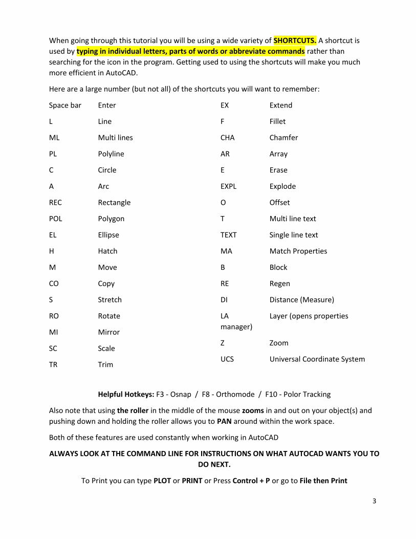
When going through this tutorial you will be using a wide variety of SHORTCUTS. A shortcut is
used by typing in individual letters, parts of words or abbreviate commands rather than
searching for the icon in the program. Getting used to using the shortcuts will make you much
more efficient in AutoCAD.
Here are a large number (but not all) of the shortcuts you will want to remember:
Space bar Enter
L Line
ML Multi lines
PL Polyline
C Circle
A Arc
REC Rectangle
POL Polygon
EL Ellipse
H Hatch
M Move
CO Copy
S Stretch
RO Rotate
MI Mirror
SC Scale
TR Trim
EX Extend
F Fillet
CHA Chamfer
AR Array
E Erase
EXPL Explode
O Offset
T Multi line text
TEXT Single line text
MA Match Properties
B Block
RE Regen
DI Distance (Measure)
LA Layer (opens properties
manager)
Z Zoom
UCS Universal Coordinate System
Helpful Hotkeys: F3 - Osnap / F8 - Orthomode / F10 - Polor Tracking
Also note that using the roller in the middle of the mouse zooms in and out on your object(s) and
pushing down and holding the roller allows you to PAN around within the work space.
Both of these features are used constantly when working in AutoCAD
ALWAYS LOOK AT THE COMMAND LINE FOR INSTRUCTIONS ON WHAT AUTOCAD WANTS YOU TO
DO NEXT.
To Print you can type PLOT or PRINT or Press Control + P or go to File then Print
Page 4
4
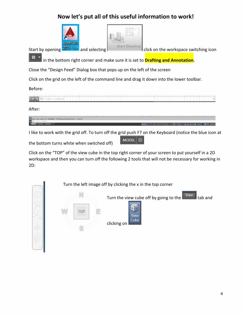
Now let’s put all of this useful information to work!
Start by opening and selecting click on the workspace switching icon
in the bottom right corner and make sure it is set to Drafting and Annotation.
Close the “Design Feed” Dialog box that pops up on the left of the screen
Click on the grid on the left of the command line and drag it down into the lower toolbar.
Before:
After:
I like to work with the grid off. To turn off the grid push F7 on the Keyboard (notice the blue icon at
the bottom turns white when switched off)
Click on the “TOP” of the view cube in the top right corner of your screen to put yourself in a 2D
workspace and then you can turn off the following 2 tools that will not be necessary for working in
2D:
Turn the left image off by clicking the x in the top corner
Turn the view cube off by going to the tab and
clicking on
Page 5
5
Go back to your “home” tab and notice all of the icons in the RIBBON at the top of the screen.
We will be using their functions but you will be using the shortcuts to use them rather than clicking
on the icons.
We will also be using the Absolute and relative coordinate systems to create our objects.
Let’s start by creating the 2 boxes on the bottom of page 2 in this tutorial:
Type L for line & ENTER then type the starting coordinate 0,0 (always watch the command line for
instructions) then the next point #2,0 & ENTER and so on. (refer to page 2 for images) Press ENTER
again when finished to end the command.
NOTE: You can “enter” back into the same command you were just in previously by pushing ENTER
again. TRY THIS NOW to start a new line for the second box
Type 4,0 as your starting point then @2,0 for your next point and so on. (refer to page 2 for images)
You should now have two boxes that look like this:
Let’s now create a box that is 1 by 1.5 and has a starting point of .5,1.5 using Absolute
Coordinates. L & ENTER to start then .5,1.5 as the start point then #1.5,1.5 as the next point then
#1.5,3 then #.5,3 then #.5,1.5 as your final point. (Remember that all points in Absolute start from
the origin)
No we will create the same rectangle in the other large rectangle using Relative Coordinates. L &
ENTER to start then 4.5,1.5 as the start point then @1,0 as the next point then @0,1.5 then @-1,0
then @0,-1.5 as your final point and ENTER to end the command. (Remember that all points in
Relative start from the last point you were at)
After completing both small rectangles you should have the following (seen on next page):
Page 6
6
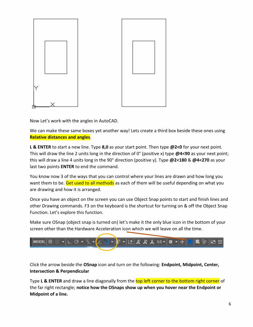
Now Let’s work with the angles in AutoCAD.
We can make these same boxes yet another way! Lets create a third box beside these ones using
Relative distances and angles.
L & ENTER to start a new line. Type 8,0 as your start point. Then type @2<0 for your next point.
This will draw the line 2 units long in the direction of 0° (positive x) type @4<90 as your next point;
this will draw a line 4 units long in the 90° direction (positive y). Type @2<180 & @4<270 as your
last two points ENTER to end the command.
You know now 3 of the ways that you can control where your lines are drawn and how long you
want them to be. Get used to all methods as each of them will be useful depending on what you
are drawing and how it is arranged.
Once you have an object on the screen you can use Object Snap points to start and finish lines and
other Drawing commands. F3 on the keyboard is the shortcut for turning on & off the Object Snap
Function. Let’s explore this function.
Make sure OSnap (object snap is turned on) let’s make it the only blue icon in the bottom of your
screen other than the Hardware Acceleration icon which we will leave on all the time.
Click the arrow beside the OSnap icon and turn on the following: Endpoint, Midpoint, Center,
Intersection & Perpendicular
Type L & ENTER and draw a line diagonally from the top left corner to the bottom right corner of
the far right rectangle; notice how the OSnaps show up when you hover near the Endpoint or
Midpoint of a line.
Page 7
7
Repeat this going from the top right to bottom left and make a circle with a Radius of 1at the
intersection of the two lines.
You should now have this on your screen:
SAVE this drawing Go to your personal folder under your student #, then to “my
documents” folder, Create a new folder in here called “Drafting”.
SAVE AS “YOUR NAME_2D TUTORIAL” WE WILL COME BACK TO IT LATER
NOW TIME FOR A FEW SKILL BUILDING ASSIGNMENTS &
SOME QUIZZES TO TEST WHAT YOU HAVE LEARNED
Remember that AutoCAD is a very sophisticated program and it takes years to master
it. We are looking to develop a basic understanding of how the software functions
and the best and easiest ways to go about a certain task.
Page 8
8
AutoCAD Quiz #1
1) From which direction does AutoCAD start measuring angles?
a) 12 O'Clock
b) 3 O'Clock
c) 6 O'Clock
d) 9 O'Clock
2) What does UCS stand for?
a) Unfortunate CAD System
b) Uncontrolled Coordinate Sectors
c) Universal Coordinate System
d) Unbelievable CAD Settings
3) When drawing in 2D, what axis do you not work with?
a) X
b) Y
c) Z
d) UCS
4) Is 300° the same as -60° in a drawing?
a) Yes
b) No
c) Not Always
d) Never
Feel free to have AutoCAD open and try different things to help you answer these
questions.
Page 9
9
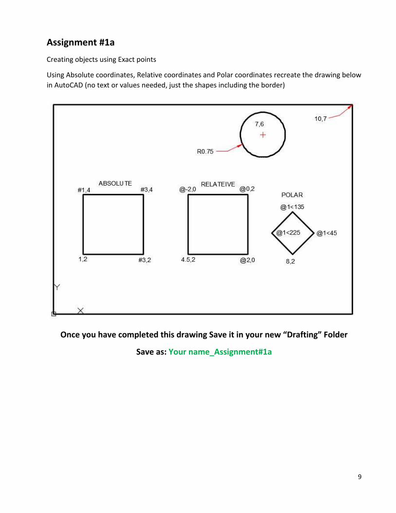
Assignment #1a
Creating objects using Exact points
Using Absolute coordinates, Relative coordinates and Polar coordinates recreate the drawing below
in AutoCAD (no text or values needed, just the shapes including the border)
Once you have completed this drawing Save it in your new “Drafting” Folder
Save as: Your name_Assignment#1a
Page 10
10
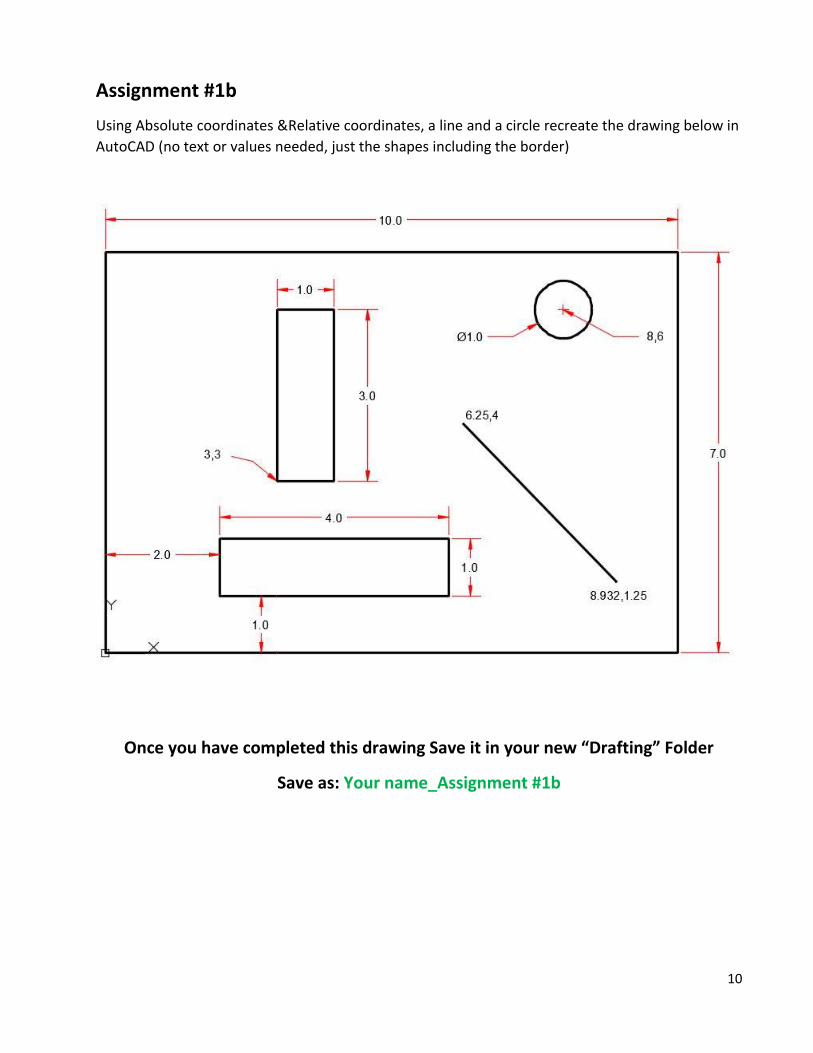
Assignment #1b
Using Absolute coordinates &Relative coordinates, a line and a circle recreate the drawing below in
AutoCAD (no text or values needed, just the shapes including the border)
Once you have completed this drawing Save it in your new “Drafting” Folder
Save as: Your name_Assignment #1b
Page 11
11
AutoCAD Quiz #2
1) Which one of these will NOT start the Print Command?
a) Typing PLOT
b) Typing PRINT
c) Pressing Control + P
d) Pressing Alt + P
2) What should you pay attention to when learning AutoCAD?
a) The Command Line
b) The Status Bar
c) The Title Bar
d) Tool Icons
3) Polar coordinates are used mostly for drawing...?
a) Circles
b) Arcs
c) Vertical lines
d) Angled lines
4) Which keystrokes will UNDO a command?
a) Control + U
b) Alt + U
c) Control + Z
d) Alt + Z
Feel free to have AutoCAD open and try different things to help you answer these
questions.
Page 12
12
Assignment #2a
Copy the drawing below (no text or values needed, just the shapes including the border)
Absolute coordinates for BOX 1
Relative coordinates for BOX 2
Mline for BOX 3 with a Scale of .15 and Justification of TOP (Draw the box in a clockwise
direction and use C (for close) as your last point)
Create the lines next using the coordinates in the drawing (method of your choice)
Create the inner circle Ø1 then use the Offset tool to create the second circle Ø1.25
Once you have created everything above:
Trim the top of the vertical line above BOX 1 down to the horizontal line
Extend the vertical line above BOX 2 up to the horizontal line
Draw a line from the center of the circles to the midpoint of the vertical line above BOX 2
What your drawing should look like at the end is shown on the next page
Page 13
13
Final product for Assignment #2a
SAVE into your Drafting folder as Your name_Assignment #2a
Assignment #2b (SAVE as Your Name_Assignment#2b)
Copy the drawing below (no text or values needed, just the shapes including the border)
Mline for box moving in a counterclockwise direction (use C for Close as your last
point) Line tool and Osnaps to create the two lines perpendicular to each other
Page 14
14
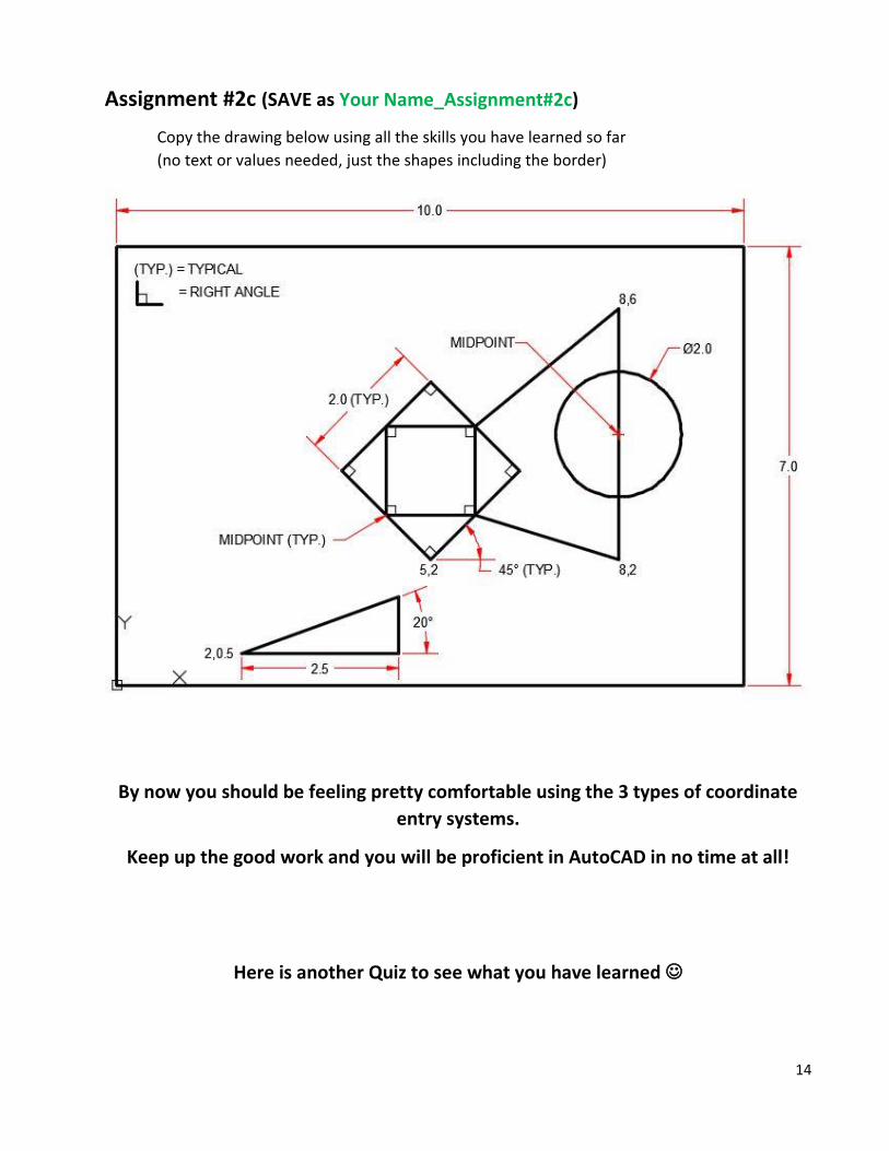
Assignment #2c (SAVE as Your Name_Assignment#2c)
Copy the drawing below using all the skills you have learned so far
(no text or values needed, just the shapes including the border)
By now you should be feeling pretty comfortable using the 3 types of coordinate
entry systems.
Keep up the good work and you will be proficient in AutoCAD in no time at all!
Here is another Quiz to see what you have learned
Page 15
15
AutoCAD Quiz #3
1) When using the TRIM Command, which do you select first
a) The cutting edges
b) The object to be trimmed
c) Everything
d) Nothing
2) How many snap points does an object have?
a) One
b) Two
c) Depends on the object
d) At least four
3) How many grips does an object have?
a) One
b) Two
c) Depends on the object
d) At least four
4) How many point do you need to define for the rectangle command?
a) One
b) Two
c) Four
d) None
5) How many AutoCAD objects are in a rectangle drawn with the rectangle command?
a) None
b) One
c) Four
d) Eight
Feel free to have AutoCAD open and try different things to help you answer these
questions.
Page 16
16
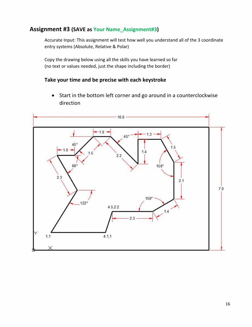
Assignment #3 (SAVE as Your Name_Assignment#3)
Accurate Input: This assignment will test how well you understand all of the 3 coordinate
entry systems (Absolute, Relative & Polar)
Copy the drawing below using all the skills you have learned so far
(no text or values needed, just the shape including the border)
Take your time and be precise with each keystroke
Start in the bottom left corner and go around in a counterclockwise
direction
Page 17
17
Some More Skill Testing Questions
AutoCAD Quiz #4
1) If you draw a line at 270° it will point:
a) Up
b) Down
c) Left
d) Right
2) How long will a line from 1,4 to 4,4 be?
a) 4 units
b) 8 units
c) Can’t from those coordinates
d) 3 units
3) How long will a line from 1,4 to @4<5 be?
a) 3 units
b) 4 units
c) 5 units
d) 3.546 units
4) How many point do you need to draw a line using Absolute Coordinates?
a) None
b) 1
c) 2
d) 4
Feel free to have AutoCAD open and try different things to help you answer these
questions.
Page 18
18
AutoCAD Quiz #5
1) When selecting objects, pressing ‘L’ will
a) Select lines only
b) Select objects when you move your mouse to the left
c) Select the last object created
d) Select the last object you modified
2) Pressing Shift while you are selecting will?
a) Allow you to draw a window
b) Automatically dialect the object(s)
c) Remove the nest selected object from the set
d) Highlight the selected objects
3) Pressing ‘F’ when selecting objects will:
a) Allow you to draw a fence
b) Finish the selection set
c) Limit you to five objects
d) Allow you to find specific text
4) How do you select the last set of objects you selected?
a) Type ‘L’
b) Type ‘P’
c) Type ‘H’ to highlight them
d) You cannot do this
Feel free to have AutoCAD open and try different things to help you answer these
questions.
Page 19
19
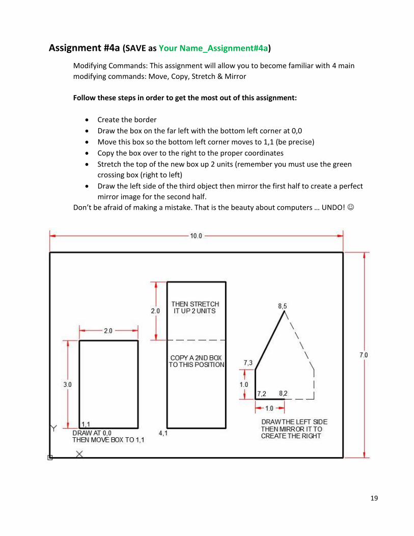
Assignment #4a (SAVE as Your Name_Assignment#4a)
Modifying Commands: This assignment will allow you to become familiar with 4 main
modifying commands: Move, Copy, Stretch & Mirror
Follow these steps in order to get the most out of this assignment:
Create the border
Draw the box on the far left with the bottom left corner at 0,0
Move this box so the bottom left corner moves to 1,1 (be precise)
Copy the box over to the right to the proper coordinates
Stretch the top of the new box up 2 units (remember you must use the green
crossing box (right to left)
Draw the left side of the third object then mirror the first half to create a perfect
mirror image for the second half.
Don’t be afraid of making a mistake. That is the beauty about computers … UNDO!
Page 20
20
Assignment #4b (SAVE as Your Name_Assignment#4b)
Modifying Commands: This assignment will show you the TTR (Tangent, Tangent, Radius)
command that can be helpful to create odd shaped curved objects.
Follow these steps in order to get the most out of this assignment:
Create the border
Draw the circle on the left with the center point of 3,3.25
Draw the circle on the right
Create the third and final circle using TTR (an option once you start the circle
command (follow the instructions in the command line))
Connect the bottoms of these circles using a line and the “quadrant” Osnap
Trim out all unnecessary lines
Voila you are done!
Page 21
21
AutoCAD Quiz #6
1) What is the best way of drawing a rectangle?
a) Using the line command
b) Using the polyline command
c) Using the rectangle command
d) Using the multiline command
2) To move something 4 units to the right, what would be the 2nd point of displacement?
a) @4,0
b) @4<0
c) Neither a nor b work
d) Both a and b work
3) How should you select objects when using the stretch command?
a) With a crossing box (the green one)
b) With a window (the blue one)
c) Pick them one at a time
d) Hold the shift key while selecting
e) Type ‘S’
4) The origin of a drawing is at:
a) The first point you select
b) 0,0
c) A random point in space
d) 10,10
Feel free to have AutoCAD open and try different things to help you answer these
questions.
Page 22
22
Assignment #5a (SAVE as Your Name_Assignment#5a)
Modifying Commands: This assignment will have you preform new modifying commands
focusing on Fillet, Chamfer and Array
Follow these steps in order to get the most out of this assignment:
Create the border
Create the bottom left box (your choice of technique)
Copy this box up to create the next two above it (be precise with distances)
Create only one of the small boxes (the one in the bottom left of the group)
Array this box using the Rectangular Array modifier
Draw the circle in the top right in the correct place
Draw one of the lines shown inside the circle 1 unit long
Array the line using the polar Array modifier
Fillet the corners of the middle of the three boxes as shown
Chamfer the corners of the top box as shown
Always remember to pay attention to the Command Line at the bottom of your screen for
instructions on what the program wants next for the command to work properly
Well Done that was a tough one!
Page 23
23
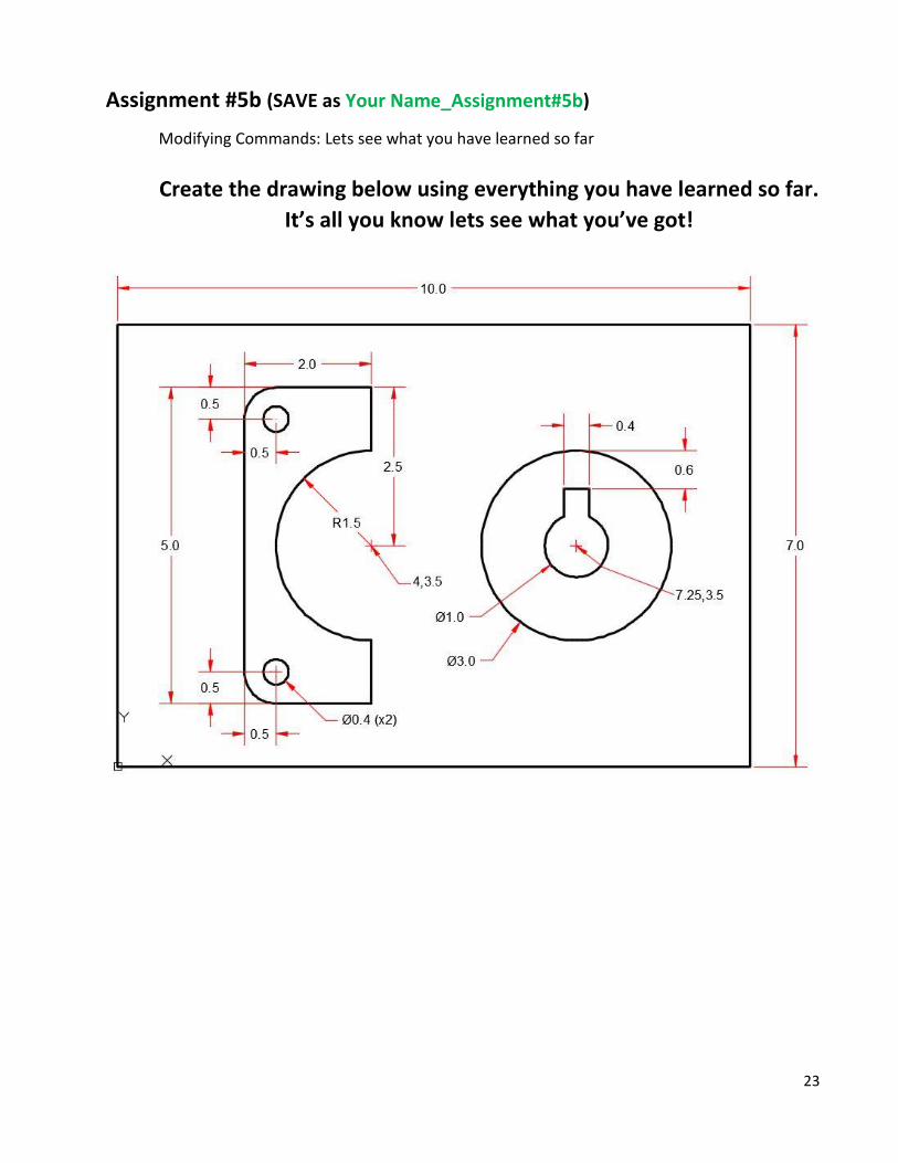
Assignment #5b (SAVE as Your Name_Assignment#5b)
Modifying Commands: Lets see what you have learned so far
Create the drawing below using everything you have learned so far.
It’s all you know lets see what you’ve got!
Page 24
24
AutoCAD Quiz #7
1) Objects are rotated around the:
a) Base point
b) Bottom right of the object
c) Center of the object
d) Origin
2) The fillet command creates:
a) Sharp square corners
b) Rounded corners to a desired radius
c) A circle
d) Both a and b can be done
3) A polar array creates new objects:
a) In a grid pattern
b) In a straight line
c) In a circular pattern
d) In an northern pattern
4) The distances of a chamfer are:
a) Always different
b) Always the same
c) Sometimes different
d) Never the same
Feel free to have AutoCAD open and try different things to help you answer these
questions.
Page 25
25
Assignment #6
Open “Your Name_Assignment#5” and SAVE AS Your Name_Assignment#6 this copies
all the same information of one file into a second file to modify
Layers, Text & Dimensioning: Brand new, very important skills to learn
Why do we have layers? Organization … just like folders in a computer
Create 3 new layers by:
Go to Layer Properties
Click the new layer icon
Create 3 layers called:
o Text Change this layer to Green
o Dims (for dimensions) Change the color of this one to Red
o Object
Make the Text layer your current layer and lets make some text!
in the tab or type “TEXT” to start the command Click
Follow the dirctions in the command line filling out the information as follows:
Start point: 0.125,0.125
Text height: 0.25
Text rotation angle: 0
Type in ALL CAPS: YOUR NAME ASSIGNMENT #6
PRESS ENTER TWICE (this ends the command, pressing enter once allows you to add another line of
text that will be a separate object one the command is completed)
Almost Done!
Page 26
26
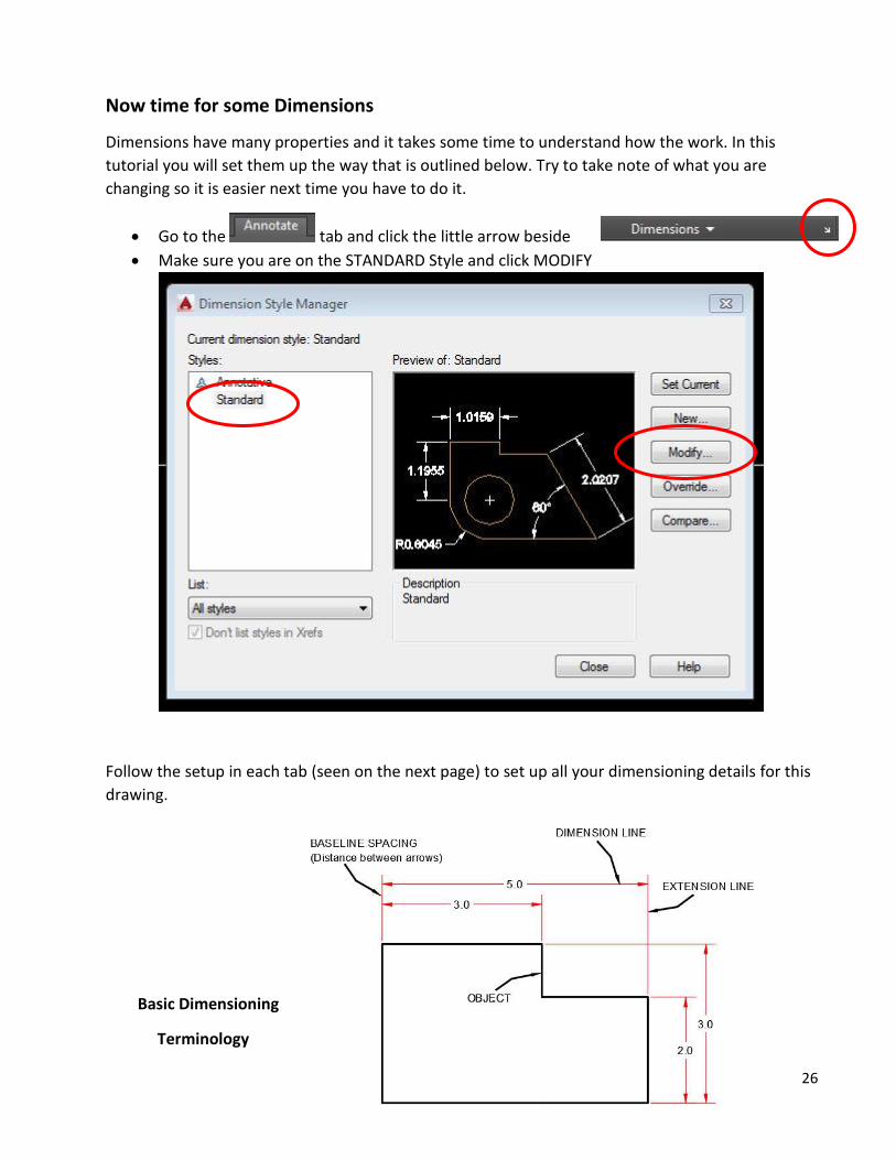
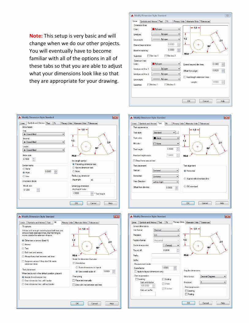
Now time for some Dimensions
Dimensions have many properties and it takes some time to understand how the work. In this
tutorial you will set them up the way that is outlined below. Try to take note of what you are
changing so it is easier next time you have to do it.
Go to the tab and click the little arrow beside
Make sure you are on the STANDARD Style and click MODIFY
Follow the setup in each tab (seen on the next page) to set up all your dimensioning details for this
drawing.
Basic Dimensioning
Terminology
Page 27
27
Note: This setup is very basic and will
change when we do our other projects.
You will eventually have to become
familiar with all of the options in all of
these tabs so that you are able to adjust
what your dimensions look like so that
they are appropriate for your drawing.
Page 28
28
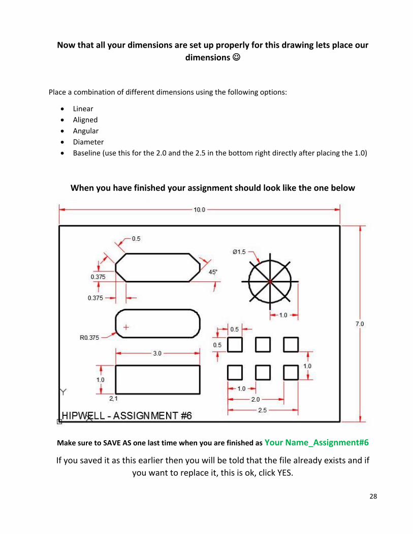
Now that all your dimensions are set up properly for this drawing lets place our
dimensions
Place a combination of different dimensions using the following options:
Linear
Aligned
Angular
Diameter
Baseline (use this for the 2.0 and the 2.5 in the bottom right directly after placing the 1.0)
When you have finished your assignment should look like the one below
Make sure to SAVE AS one last time when you are finished as Your Name_Assignment#6
If you saved it as this earlier then you will be told that the file already exists and if
you want to replace it, this is ok, click YES.
Page 29
29
AutoCAD Quiz #8
1) You should use Osnaps when you dimension:
a) Never
b) Always
c) Only on lines
d) Only on arcs and circles
2) How many layers should a drawing have?
a) 1
b) 10
c) One for each object
d) As many as are needed to clearly display the objects
3) When can you change the height of your text?
a) Only when you start a new drawing
b) Only in a special text dialog box
c) When you are starting the Text command
d) You can’t, it is pre-set by AutoCAD
4) Scaling objects makes them:
a) Bigger b) Smaller
c) It only stretches them
d) Both Bigger and Smaller
Feel free to have AutoCAD open and try different things to help you answer these
questions.
Page 30
30
Congratulations you have now completed all of the Basic AutoCAD Assignments.
Only a few more tips and tricks to cover and 2 more quick quizzes before starting
your First Design Project.
TIP #1
Direct Distance Entry
So far you have learned Absolute, Relative & Polar Coordinate Entry. DDE is another way of
entering distances that is much faster and, depending on what you are doing, just as accurate.
It is important to know and remember the 3 manual entry techniques (Absolute,
Relative & Polar) as they are necessary in many situations.
DDE allows you to only type a distance (value) and bypass the usual way of entering
coordinates
It is important that either Ortho Mode or Polar Mode is turned on!
Here is how it works:
Start the line command
Pick your “Start Point” as you normally would with either coordinates or using
an Osnap.
Drag your mouse in the direction you want the line to go (make sure you are
snapped in on a Polar or Ortho line)
Type the distance you want the line to be
Voila! All done.
This method makes it very fast to draw objects that have square corners or are at
simple angles or any increments of 5°
Try it out and see how fast you can draw the box on the next page
Page 31
31
Use a Polyline with DDE to create the object above
Start from the UCS Icon at 0,0 and go in a clockwise direction
Use C for Close function to draw the last line and end the command
You probably notice that this is a much easier way of entering information, but
remember that it can not always be used and we do need to know the 3 other styles
(Absolute, Relative & Polar)
Page 32
32
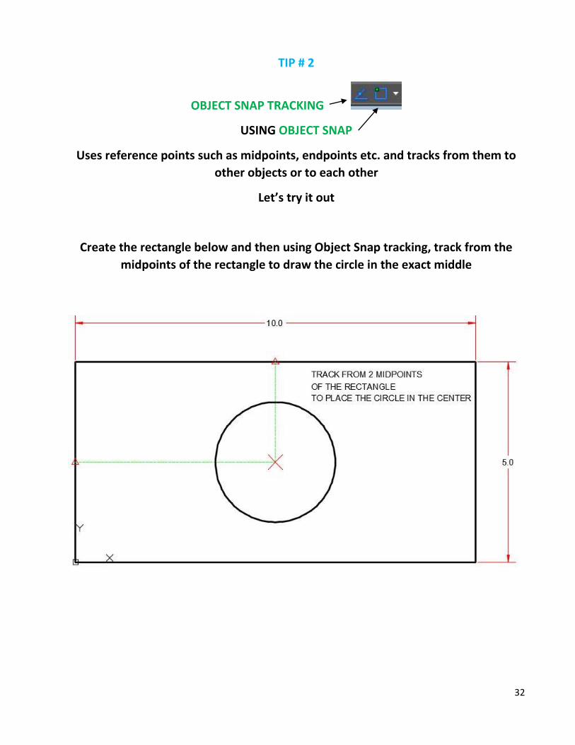
TIP # 2
OBJECT SNAP TRACKING
USING OBJECT SNAP
Uses reference points such as midpoints, endpoints etc. and tracks from them to
other objects or to each other
Let’s try it out
Create the rectangle below and then using Object Snap tracking, track from the
midpoints of the rectangle to draw the circle in the exact middle
Page 33
33
AutoCAD Quiz #9
1) DDE (Direct Distance Entry) can be used in which direction?
a) Right
b) Left
c) All
d) Any that are set with Ortho or Polar tracking
2) When using Object Snap Tracking, you should turn on:
a) Osnap
b) Otrack
c) Neither
d) Both Osnap and Otrack
3) When setting up Polar Tracking, the Increment Angle:
a) Locks you into one angle
b) Sets multiples of the selected angle
c) Doesn’t really do anything
d) Makes you a master of drafting
4) Object tracking works only with:
a) Midpoints
b) Endpoints
c) Any osnap
d) Anywhere on the screen
Feel free to have AutoCAD open and try different things to help you answer these
questions.
Page 34
34
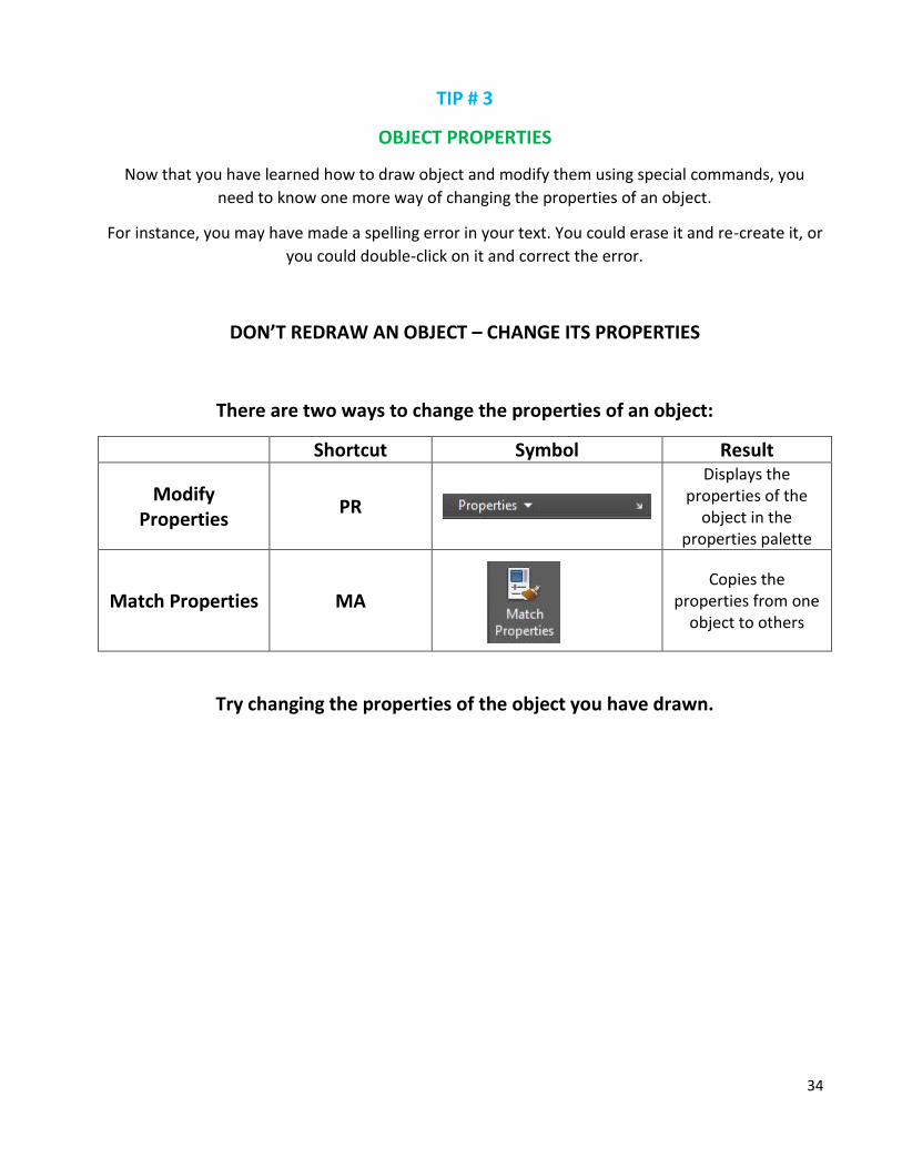
TIP # 3
OBJECT PROPERTIES
Now that you have learned how to draw object and modify them using special commands, you
need to know one more way of changing the properties of an object.
For instance, you may have made a spelling error in your text. You could erase it and re-create it, or
you could double-click on it and correct the error.
DON’T REDRAW AN OBJECT – CHANGE ITS PROPERTIES
There are two ways to change the properties of an object:
Shortcut Symbol Result
Modify Properties
PR
Displays the properties of the
object in the properties palette
Match Properties MA
Copies the properties from one
object to others
Try changing the properties of the object you have drawn.
Page 35
35
AutoCAD Quiz #10
1) How can you change an object’s properties?
a) Select it and press the properties icon
b) Select, right click and choose properties
c) Double click the object
d) All of the above
2) Double clicking on a text object allows you to change its layer.
a) Yes
b) No
c) Only if it is on the TEST layer
d) Only if you have 2 layers
3) If you select a line and a rectangle and view the properties:
a) You will see only limited properties
b) You will see all the properties
c) You will see the properties of the first selected object
d) You will not see any properties
4) When you want to close the properties palette:
a) Type CLOSE
b) Move it off the screen
c) Click the X in the top left of the palette
d) Deselect the object
5) How many AutoCAD objects are in a rectangle drawn with the line command?
a) None
b) One
c) Four
d) Eight
Feel free to have AutoCAD open and try different things to help you answer these
questions.
Page 36
36
Now let’s have some fun using shortcuts on the keyboard to modify our blocks and
create new objects using all of the skills you have just learned!
Open your drawing named “Your Name_2D Tutorial”
And SAVE AS “Your Name_2D Tutorial Complete”
See if you can make your drawing look like the one on the next page using only shortcuts on the
keyboard and inputting coordinates in either Absolute or Relative (whichever makes your life easier
– We all like to make our lives easier and knowing how all of these little things work will make all
the difference)
USEFUL TOOLS INCLUDE:
DI (measure / distance)
S (Stretch) Use a Crossing box (the green one) and place the corners you want to stretch within the
box.
MI (Mirror) Select the object you want to make a mirror image of & ENTER then select the line
(plane) you want to mirror them across (use your OSnaps).
TR (Trim) Select the lines you want to trim with first & ENTER then the line segments or parts you
want to get rid of.
EX (Extend) Select the line you want to extend to & ENTER then the line you want to extend
RO (Rotate) Select the object you want to rotate & ENTER then select the base point you want to
rotate the object around.
F (Fillet) Type R (for Radius) and type the radius you want to use & ENTER then select the two lines
you want to fillet together.
M (Move) Select the objects you want to move & ENTER then select a base point and type in the
appropriate coordinates.
NOTE: you may want to create a line or two to use temporarily to make things easier and then
Erase (E) them after.
Page 37
37
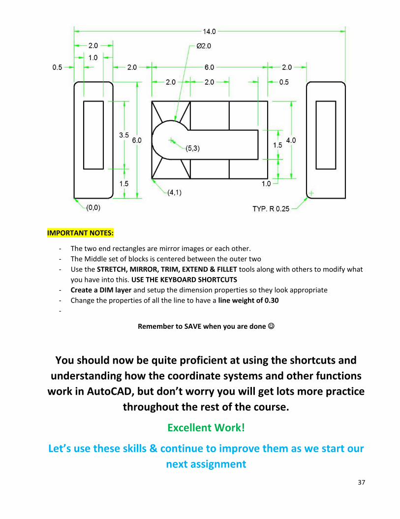
IMPORTANT NOTES:
- The two end rectangles are mirror images or each other.
- The Middle set of blocks is centered between the outer two
- Use the STRETCH, MIRROR, TRIM, EXTEND & FILLET tools along with others to modify what
you have into this. USE THE KEYBOARD SHORTCUTS
- Create a DIM layer and setup the dimension properties so they look appropriate
- Change the properties of all the line to have a line weight of 0.30
-
Remember to SAVE when you are done
You should now be quite proficient at using the shortcuts and
understanding how the coordinate systems and other functions
work in AutoCAD, but don’t worry you will get lots more practice
throughout the rest of the course.
Excellent Work!
Let’s use these skills & continue to improve them as we start our
next assignment