Robotics and Telematics 3D Point Cloud Processing 7/23/14 1 The image depicts how our robot Irma3D sees itself in a mirror. The laser looking into itself creates distortions as well as changes in intensity that give the robot a single eye, complete with iris and pupil. Thus, the image is called "Self Portrait with Duckling". 3D Point Cloud Processing Prof. Dr. Andreas Nüchter Basic Data Structures
Transcript
Robotics and Telematics3D Point Cloud Processing7/23/14
1
The image depicts how our robot Irma3D sees itself in a mirror. The laser looking into itself
creates distortions as well as changes in intensity that give the robot a single eye,
complete with iris and pupil. Thus, the image is called
"Self Portrait with Duckling".
3D Point CloudProcessing
Prof. Dr. Andreas Nüchter
Basic Data Structures
23D Point Cloud ProcessingDr. Andreas NüchterJuly 23, 2014
Robotics and Telematics
3D Point Cloud as ...
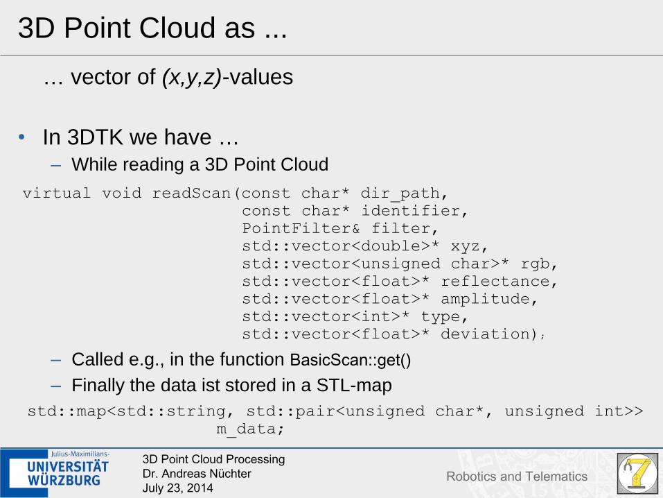
… vector of (x,y,z)-values
• In 3DTK we have …– While reading a 3D Point Cloud
33D Point Cloud ProcessingDr. Andreas NüchterJuly 23, 2014
Robotics and Telematics
3D Point Cloud as ...
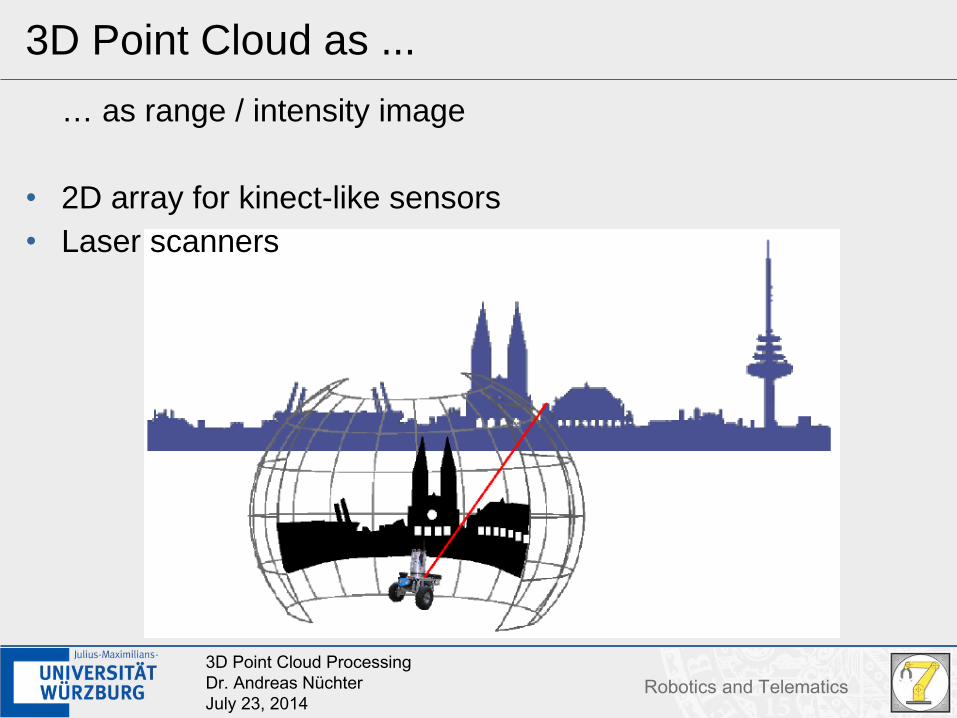
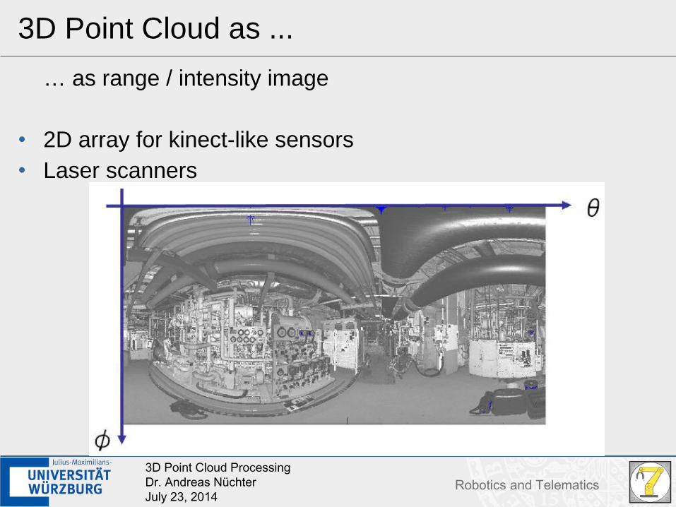
… as range / intensity image
• 2D array for kinect-like sensors• Laser scanners
43D Point Cloud ProcessingDr. Andreas NüchterJuly 23, 2014
Robotics and Telematics
3D Point Cloud as ...
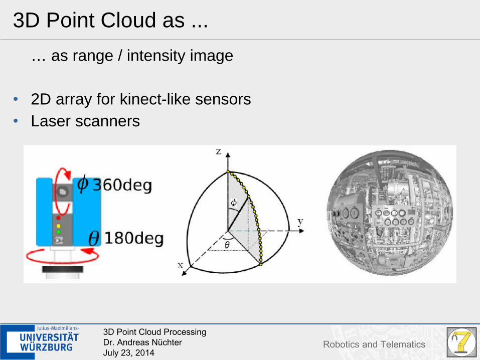
… as range / intensity image
• 2D array for kinect-like sensors• Laser scanners
53D Point Cloud ProcessingDr. Andreas NüchterJuly 23, 2014
Robotics and Telematics
3D Point Cloud as ...
… as range / intensity image
• 2D array for kinect-like sensors• Laser scanners
63D Point Cloud ProcessingDr. Andreas NüchterJuly 23, 2014
Robotics and Telematics
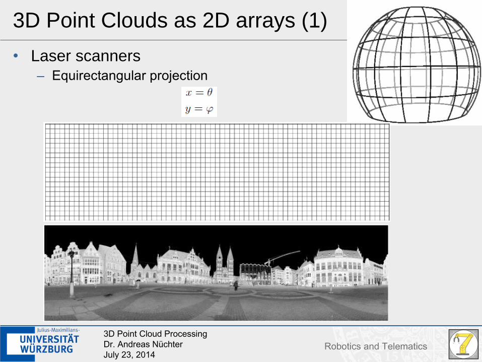
3D Point Clouds as 2D arrays (1)
• Laser scanners– Equirectangular projection
73D Point Cloud ProcessingDr. Andreas NüchterJuly 23, 2014
Robotics and Telematics
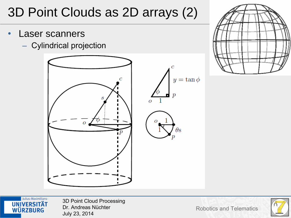
3D Point Clouds as 2D arrays (2)
• Laser scanners– Cylindrical projection
83D Point Cloud ProcessingDr. Andreas NüchterJuly 23, 2014
Robotics and Telematics
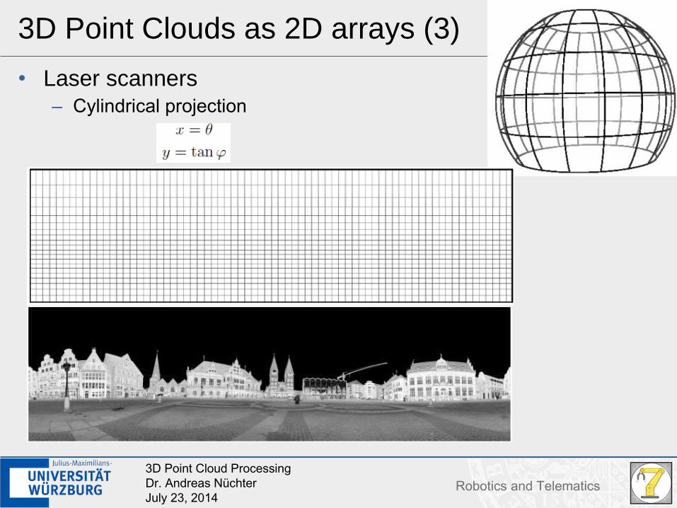
3D Point Clouds as 2D arrays (3)
• Laser scanners– Cylindrical projection
93D Point Cloud ProcessingDr. Andreas NüchterJuly 23, 2014
Robotics and Telematics
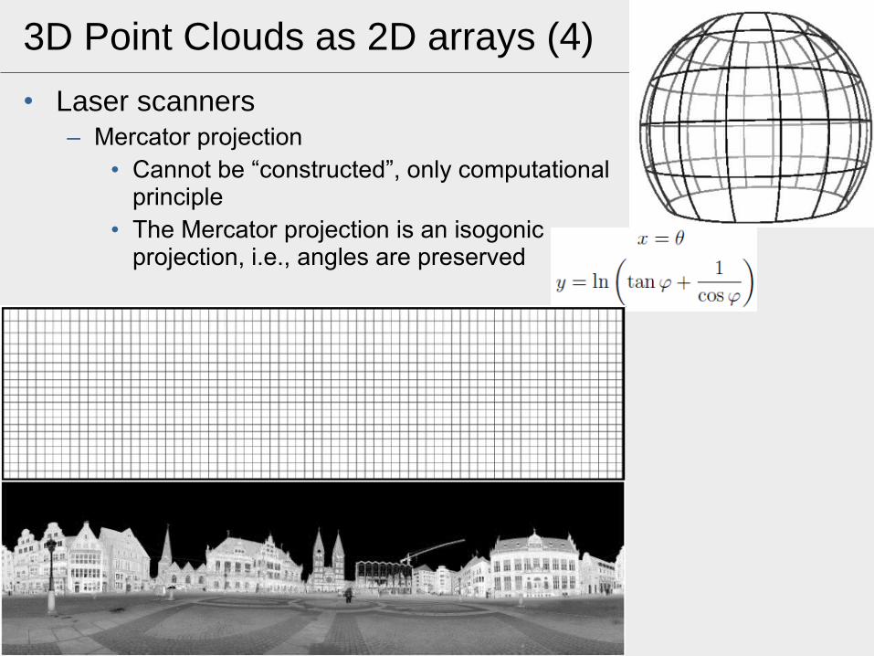
3D Point Clouds as 2D arrays (4)
• Laser scanners– Mercator projection
• Cannot be “constructed”, only computationalprinciple
• The Mercator projection is an isogonicprojection, i.e., angles are preserved
103D Point Cloud ProcessingDr. Andreas NüchterJuly 23, 2014
Robotics and Telematics
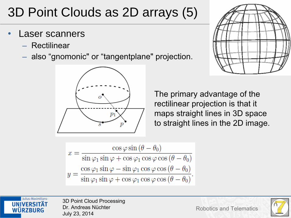
3D Point Clouds as 2D arrays (5)
• Laser scanners– Rectilinear– also “gnomonic" or “tangentplane" projection.
The primary advantage of therectilinear projection is that itmaps straight lines in 3D spaceto straight lines in the 2D image.
113D Point Cloud ProcessingDr. Andreas NüchterJuly 23, 2014
Robotics and Telematics
3D Point Clouds as 2D arrays (6)
• Laser scanners– Rectilinear– also “gnomonic" or “tangentplane" projection.
123D Point Cloud ProcessingDr. Andreas NüchterJuly 23, 2014
Robotics and Telematics
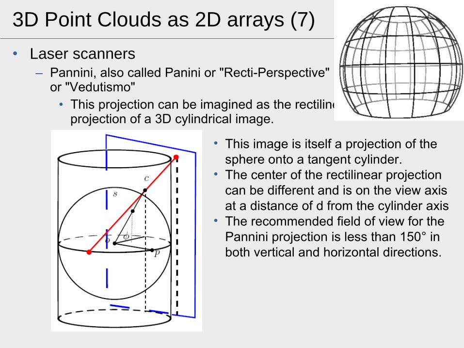
3D Point Clouds as 2D arrays (7)
• Laser scanners– Pannini, also called Panini or "Recti-Perspective"
or "Vedutismo"• This projection can be imagined as the rectilinear
projection of a 3D cylindrical image.
• This image is itself a projection of the sphere onto a tangent cylinder.
• The center of the rectilinear projection can be different and is on the view axis at a distance of d from the cylinder axis
• The recommended field of view for the Pannini projection is less than 150° in both vertical and horizontal directions.
133D Point Cloud ProcessingDr. Andreas NüchterJuly 23, 2014
Robotics and Telematics
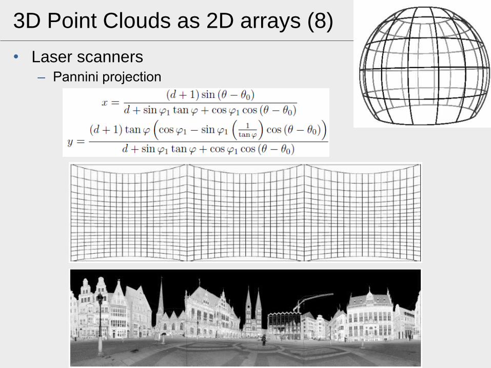
3D Point Clouds as 2D arrays (8)
• Laser scanners– Pannini projection
143D Point Cloud ProcessingDr. Andreas NüchterJuly 23, 2014
Robotics and Telematics
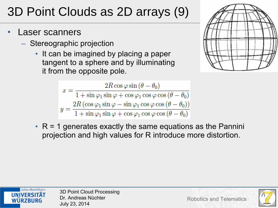
3D Point Clouds as 2D arrays (9)
• Laser scanners– Stereographic projection
• It can be imagined by placing a papertangent to a sphere and by illuminatingit from the opposite pole.
• R = 1 generates exactly the same equations as the Pannini projection and high values for R introduce more distortion.
153D Point Cloud ProcessingDr. Andreas NüchterJuly 23, 2014
Robotics and Telematics
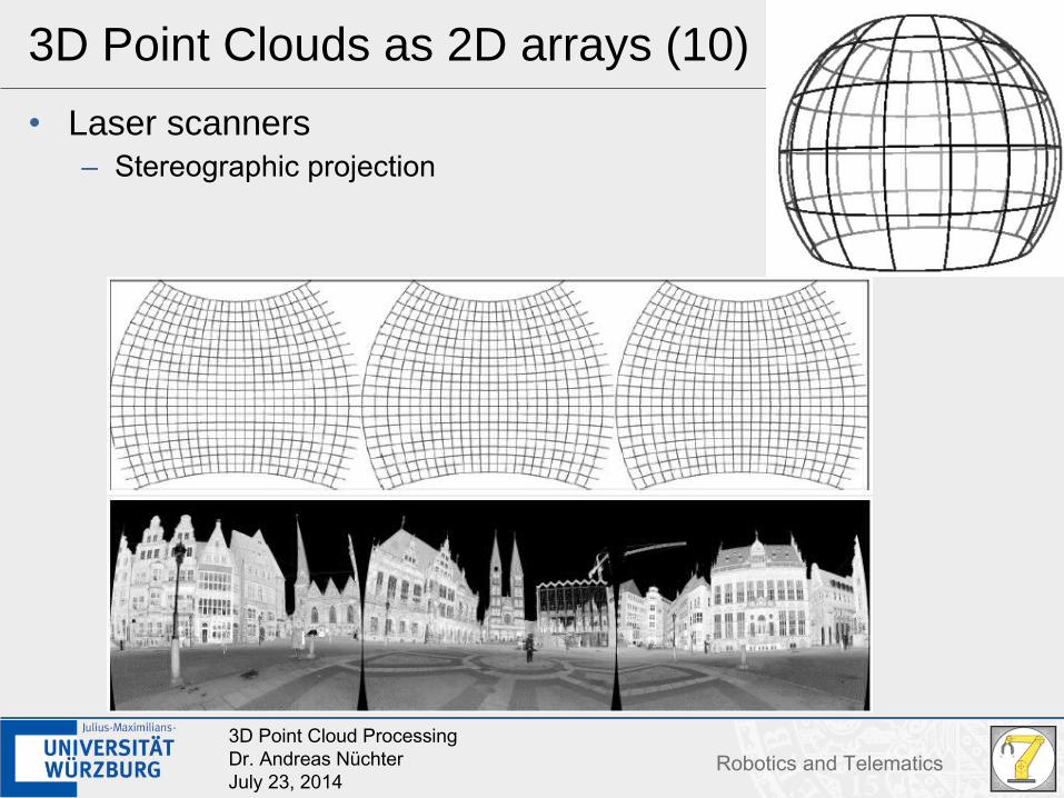
3D Point Clouds as 2D arrays (10)
• Laser scanners– Stereographic projection
163D Point Cloud ProcessingDr. Andreas NüchterJuly 23, 2014
Robotics and Telematics
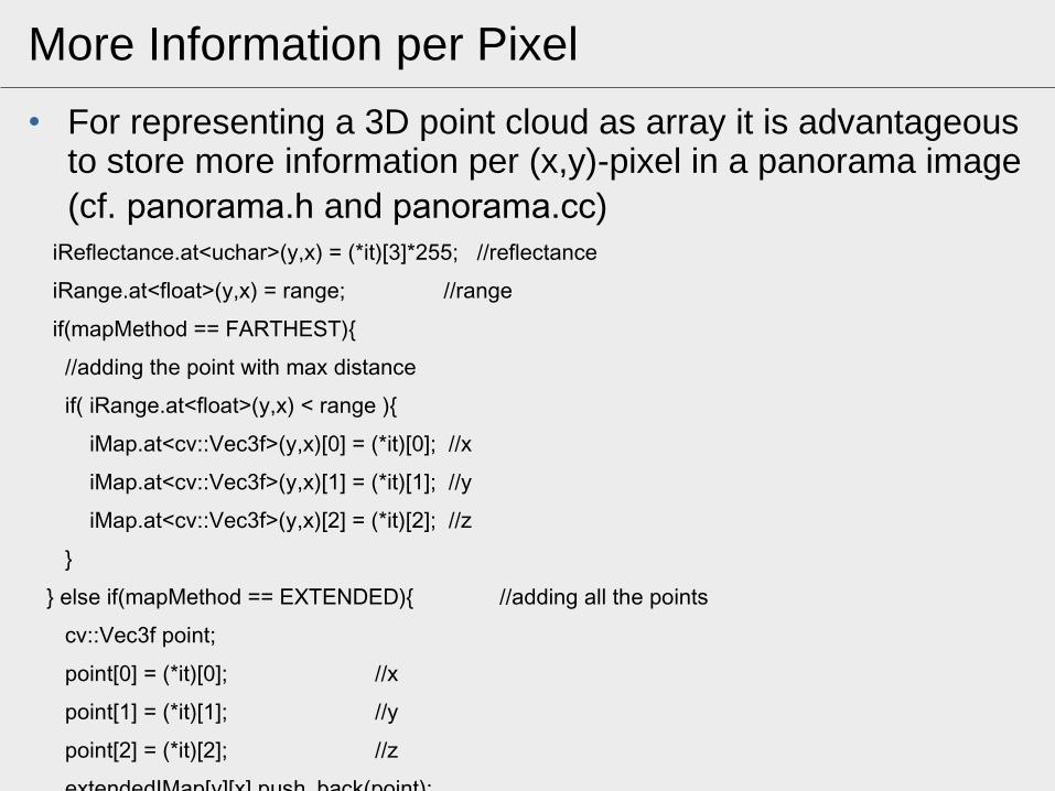
More Information per Pixel
• For representing a 3D point cloud as array it is advantageous to store more information per (x,y)-pixel in a panorama image(cf. panorama.h and panorama.cc)
} else if(mapMethod == EXTENDED){ //adding all the points
cv::Vec3f point;
point[0] = (*it)[0]; //x
point[1] = (*it)[1]; //y
point[2] = (*it)[2]; //z
extendedIMap[y][x].push_back(point);
}
173D Point Cloud ProcessingDr. Andreas NüchterJuly 23, 2014
Robotics and Telematics
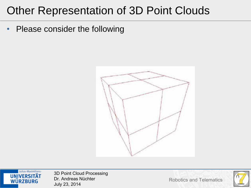
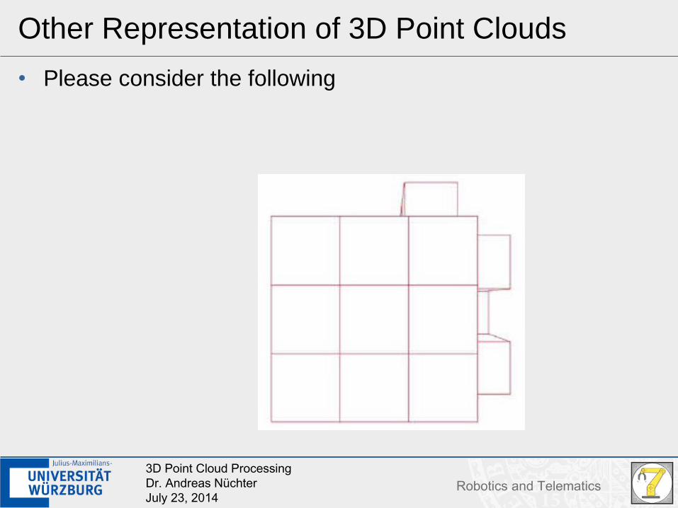
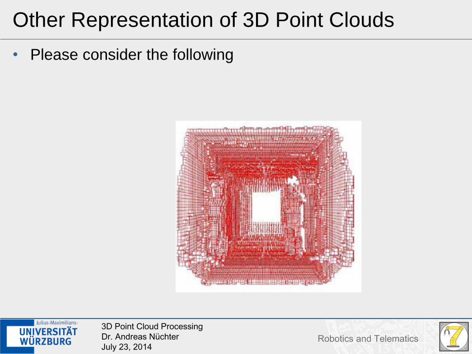
Other Representation of 3D Point Clouds
• Please consider the following
183D Point Cloud ProcessingDr. Andreas NüchterJuly 23, 2014
Robotics and Telematics
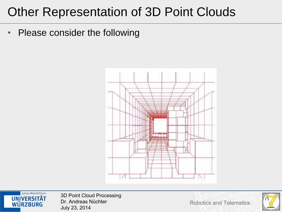
Other Representation of 3D Point Clouds
• Please consider the following
193D Point Cloud ProcessingDr. Andreas NüchterJuly 23, 2014
Robotics and Telematics
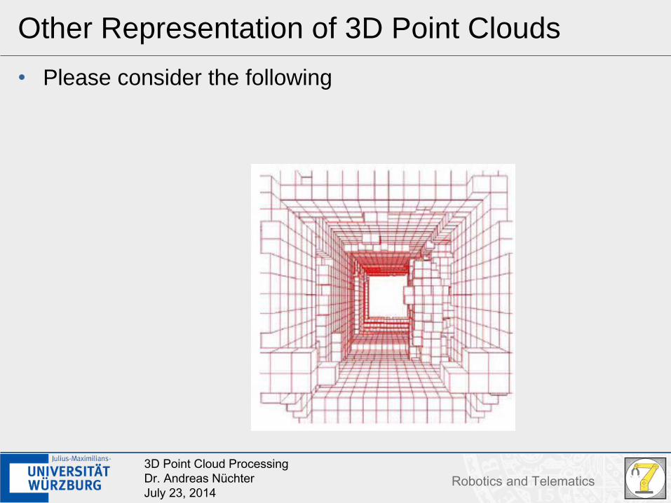
Other Representation of 3D Point Clouds
• Please consider the following
203D Point Cloud ProcessingDr. Andreas NüchterJuly 23, 2014
Robotics and Telematics
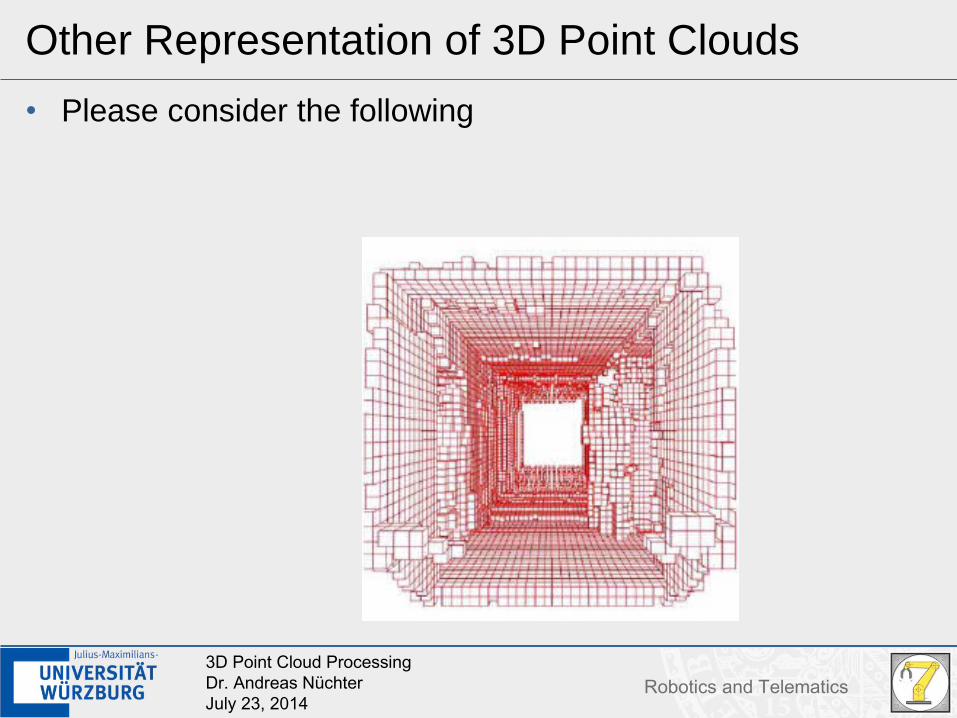
Other Representation of 3D Point Clouds
• Please consider the following
213D Point Cloud ProcessingDr. Andreas NüchterJuly 23, 2014
Robotics and Telematics
Other Representation of 3D Point Clouds
• Please consider the following
223D Point Cloud ProcessingDr. Andreas NüchterJuly 23, 2014
Robotics and Telematics
Other Representation of 3D Point Clouds
• Please consider the following
233D Point Cloud ProcessingDr. Andreas NüchterJuly 23, 2014
Robotics and Telematics
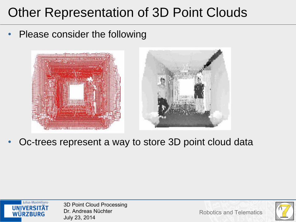
Other Representation of 3D Point Clouds
• Please consider the following
• Oc-trees represent a way to store 3D point cloud data
243D Point Cloud ProcessingDr. Andreas NüchterJuly 23, 2014
Robotics and Telematics
Further Readings
• Please consider the paper - “A Study of Projections for Key Point Based Registration of Panoramic Terrestrial 3D Laser Scans“
• Please read the paper - “Octrees for storing 3D point clouds” of the paper “One Billion Points in the Cloud – An Octree for Efficient Processing of 3D Laser Scans”
• Things to try – Viewing a high resolution outdoor 3D scan with colors
253D Point Cloud ProcessingDr. Andreas NüchterJuly 23, 2014
Robotics and Telematics
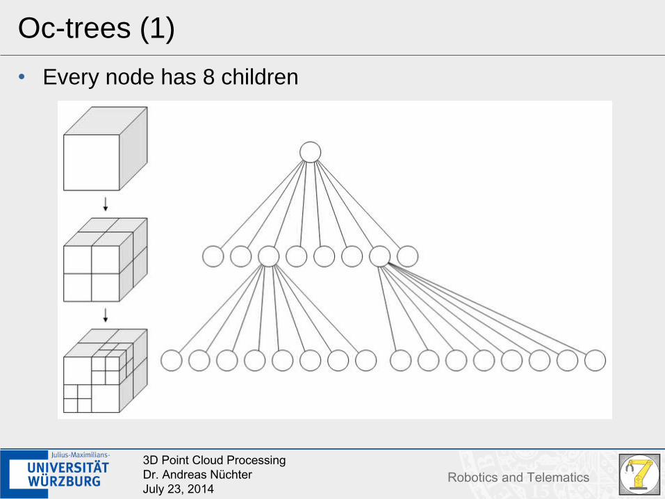
Oc-trees (1)
• Every node has 8 children
263D Point Cloud ProcessingDr. Andreas NüchterJuly 23, 2014
Robotics and Telematics
Oc-trees (2)
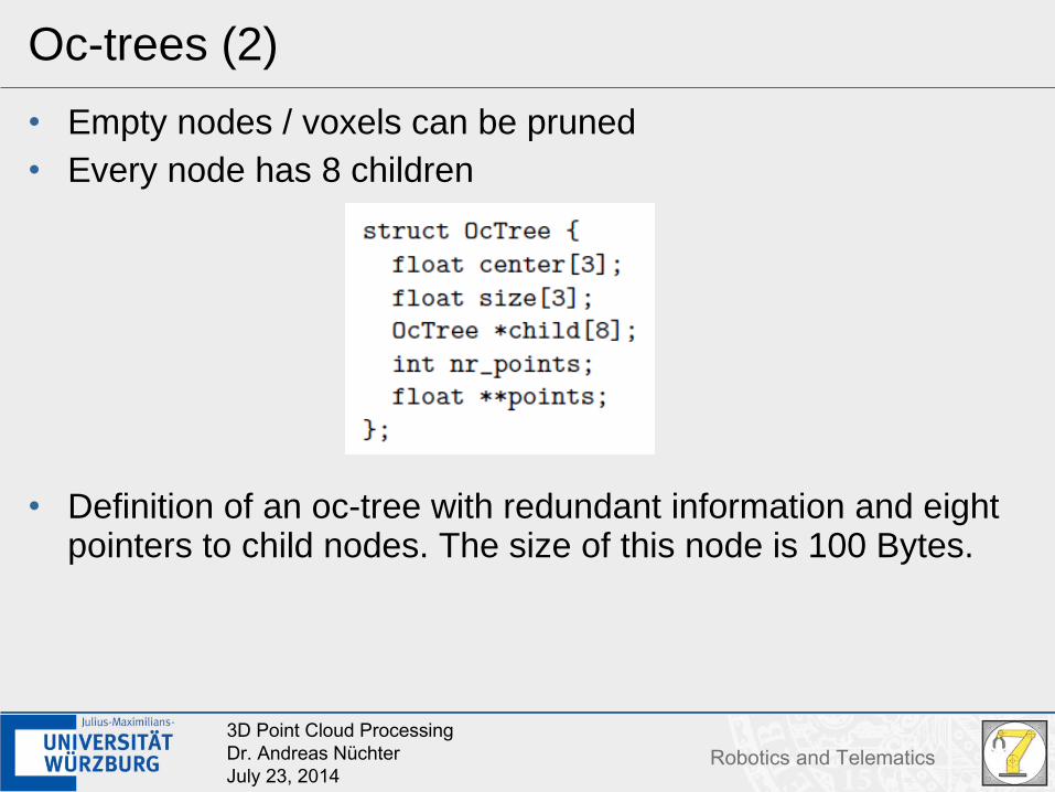
• Empty nodes / voxels can be pruned• Every node has 8 children
• Definition of an oc-tree with redundant information and eight pointers to child nodes. The size of this node is 100 Bytes.
273D Point Cloud ProcessingDr. Andreas NüchterJuly 23, 2014
Robotics and Telematics
Oc-trees (3)
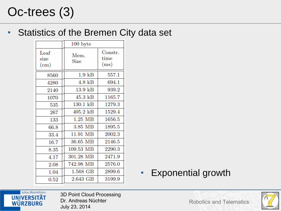
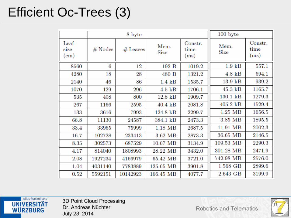
• Statistics of the Bremen City data set
• Exponential growth
283D Point Cloud ProcessingDr. Andreas NüchterJuly 23, 2014
Robotics and Telematics
Efficient Oc-Trees (1)
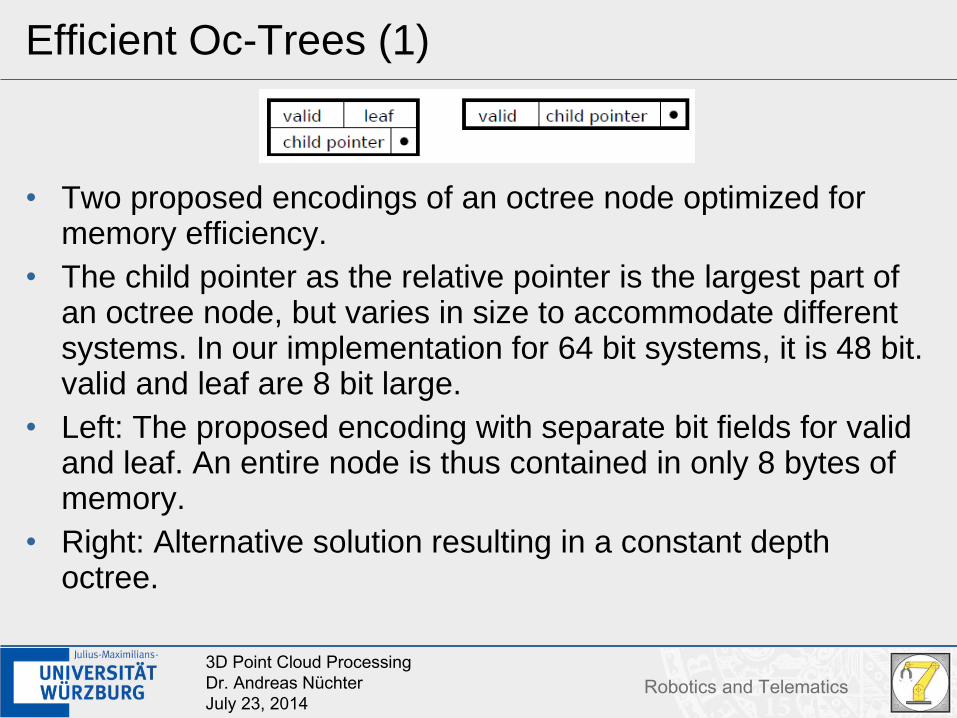
• Two proposed encodings of an octree node optimized for memory efficiency.
• The child pointer as the relative pointer is the largest part of an octree node, but varies in size to accommodate different systems. In our implementation for 64 bit systems, it is 48 bit. valid and leaf are 8 bit large.
• Left: The proposed encoding with separate bit fields for valid and leaf. An entire node is thus contained in only 8 bytes of memory.
• Right: Alternative solution resulting in a constant depth octree.
293D Point Cloud ProcessingDr. Andreas NüchterJuly 23, 2014
Robotics and Telematics
Efficient Oc-Trees (2)
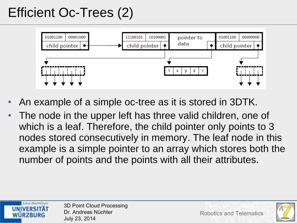
• An example of a simple oc-tree as it is stored in 3DTK.• The node in the upper left has three valid children, one of
which is a leaf. Therefore, the child pointer only points to 3 nodes stored consecutively in memory. The leaf node in this example is a simple pointer to an array which stores both the number of points and the points with all their attributes.
303D Point Cloud ProcessingDr. Andreas NüchterJuly 23, 2014
Robotics and Telematics
Efficient Oc-Trees (3)
313D Point Cloud ProcessingDr. Andreas NüchterJuly 23, 2014
Robotics and Telematics
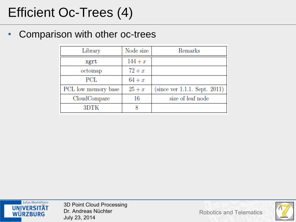
Efficient Oc-Trees (4)
• Comparison with other oc-trees
323D Point Cloud ProcessingDr. Andreas NüchterJuly 23, 2014
Robotics and Telematics
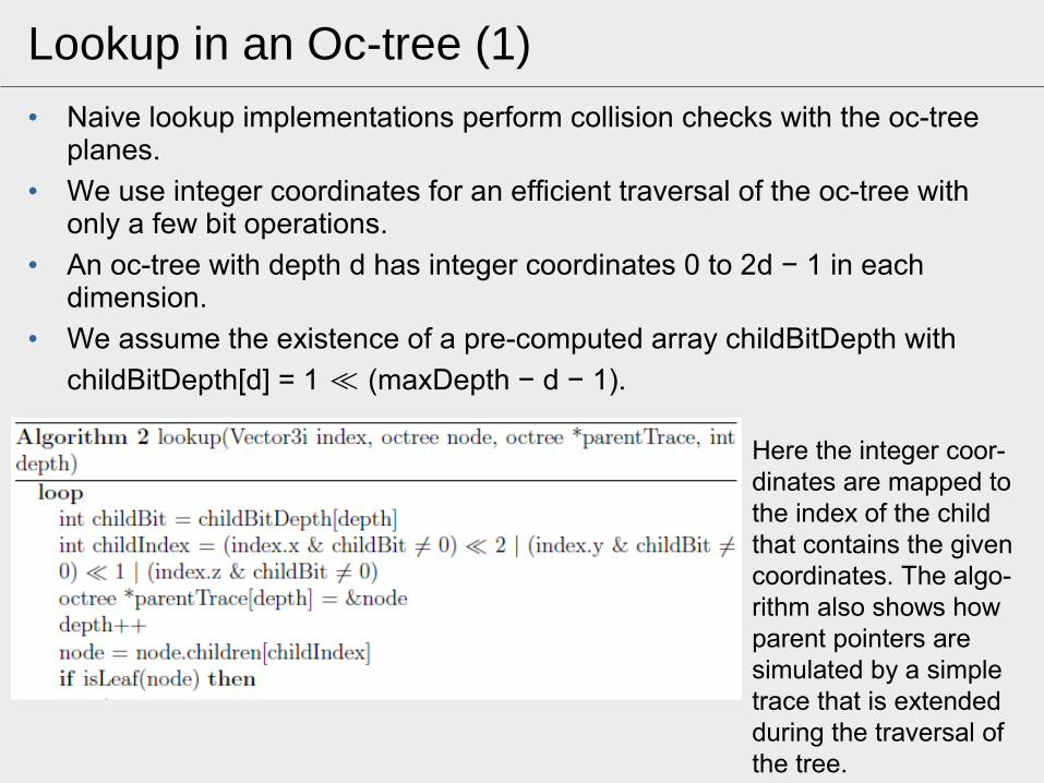
• Naive lookup implementations perform collision checks with the oc-tree planes.
• We use integer coordinates for an efficient traversal of the oc-tree with only a few bit operations.
• An oc-tree with depth d has integer coordinates 0 to 2d − 1 in each dimension.
• We assume the existence of a pre-computed array childBitDepth with
childBitDepth[d] = 1 (maxDepth − d − 1).≪
Lookup in an Oc-tree (1)
Here the integer coor-dinates are mapped to the index of the child that contains the given coordinates. The algo-rithm also shows how parent pointers are simulated by a simple trace that is extended during the traversal of the tree.
333D Point Cloud ProcessingDr. Andreas NüchterJuly 23, 2014
Robotics and Telematics
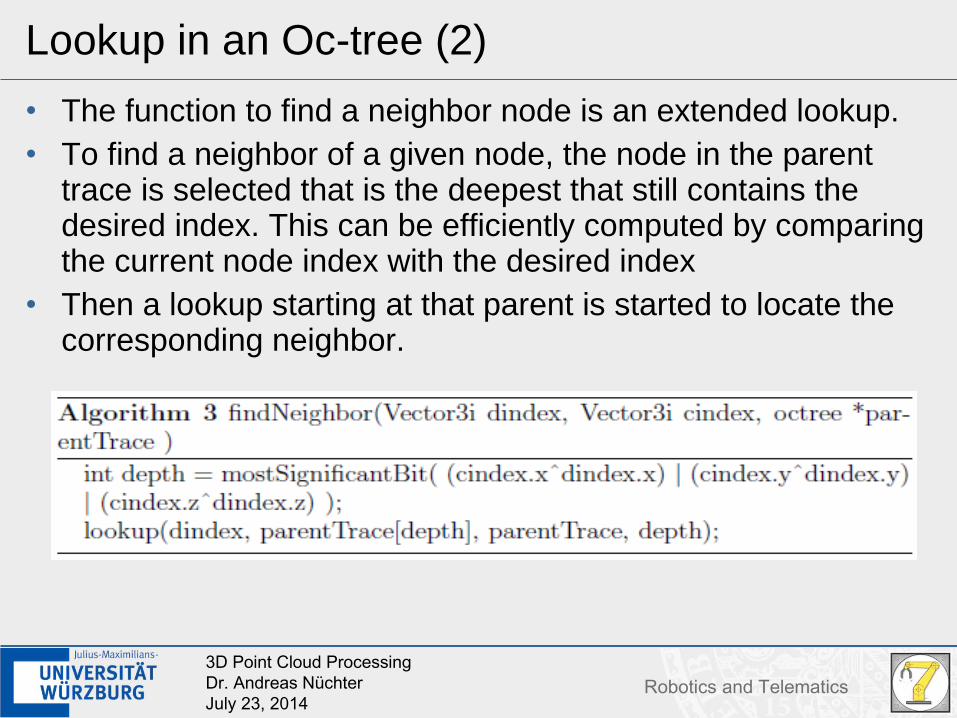
Lookup in an Oc-tree (2)
• The function to find a neighbor node is an extended lookup. • To find a neighbor of a given node, the node in the parent
trace is selected that is the deepest that still contains the desired index. This can be efficiently computed by comparing the current node index with the desired index
• Then a lookup starting at that parent is started to locate the corresponding neighbor.
343D Point Cloud ProcessingDr. Andreas NüchterJuly 23, 2014
Robotics and Telematics
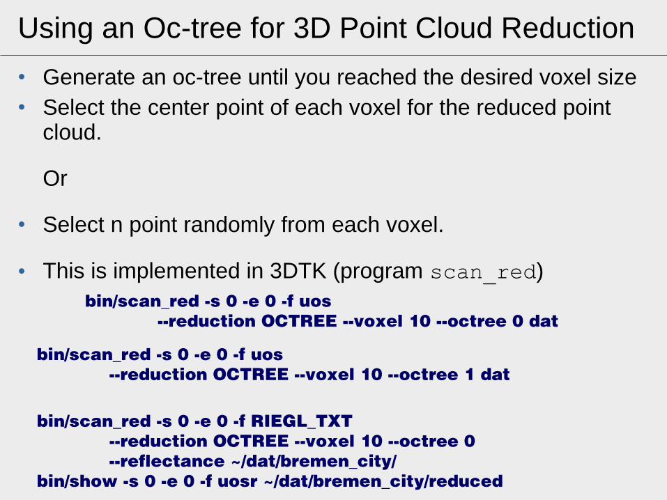
Using an Oc-tree for 3D Point Cloud Reduction
• Generate an oc-tree until you reached the desired voxel size• Select the center point of each voxel for the reduced point
cloud.
Or
• Select n point randomly from each voxel.
• This is implemented in 3DTK (program scan_red) bin/scan_red -s 0 -e 0 -f uos --reduction OCTREE --voxel 10 --octree 0 dat
353D Point Cloud ProcessingDr. Andreas NüchterJuly 23, 2014
Robotics and Telematics
3D Point Cloud as ...
… vector of (x,y,z)-values… as range/intensity images… as oc-trees
• Point Cloud reduction using Oc-trees
• Now: 3D Point Cloud reduction using range/intensity images
• How can one resize an image?
553D Point Cloud ProcessingDr. Andreas NüchterJuly 23, 2014
Robotics and Telematics
Scaling Images
• Images represent changes in intensity• Depth images represent changes in depth• Filters can pick out some changes and output “filtered
images”• Scales: things that change at fine scales are changing rapidly• Idea: Build a representation that focuses on changes
→ Fourier Transform
• standard scaling algorithms are nearest-neighbor, bilinear and bicubic interpolation
563D Point Cloud ProcessingDr. Andreas NüchterJuly 23, 2014
Robotics and Telematics
Nearest Neighbor Interpolation
573D Point Cloud ProcessingDr. Andreas NüchterJuly 23, 2014
Robotics and Telematics
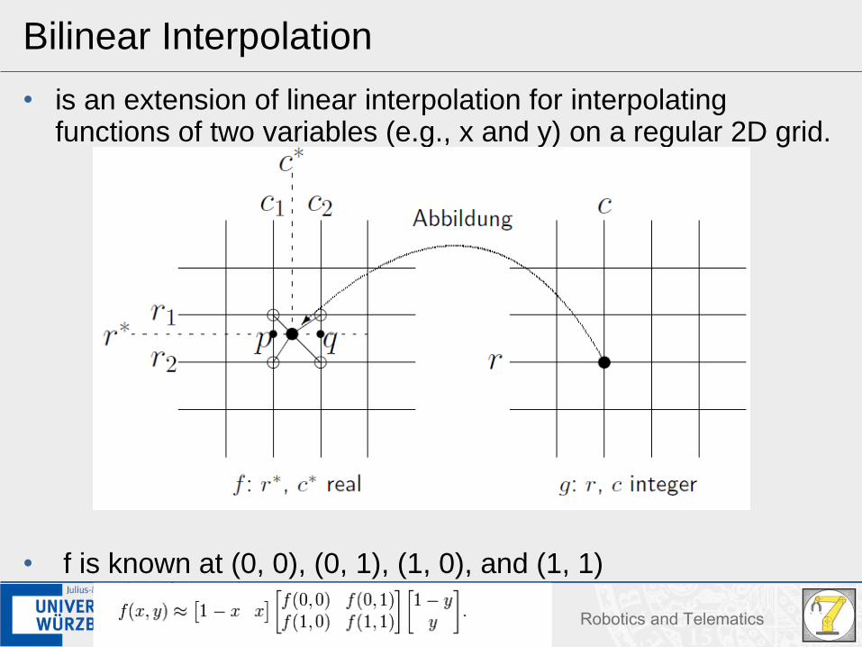
Bilinear Interpolation
• is an extension of linear interpolation for interpolating functions of two variables (e.g., x and y) on a regular 2D grid.
• f is known at (0, 0), (0, 1), (1, 0), and (1, 1)
583D Point Cloud ProcessingDr. Andreas NüchterJuly 23, 2014
Robotics and Telematics
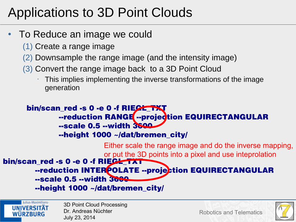
Applications to 3D Point Clouds
• To Reduce an image we could(1) Create a range image(2) Downsample the range image (and the intensity image)(3) Convert the range image back to a 3D Point Cloud
• This implies implementing the inverse transformations of the image generation