23
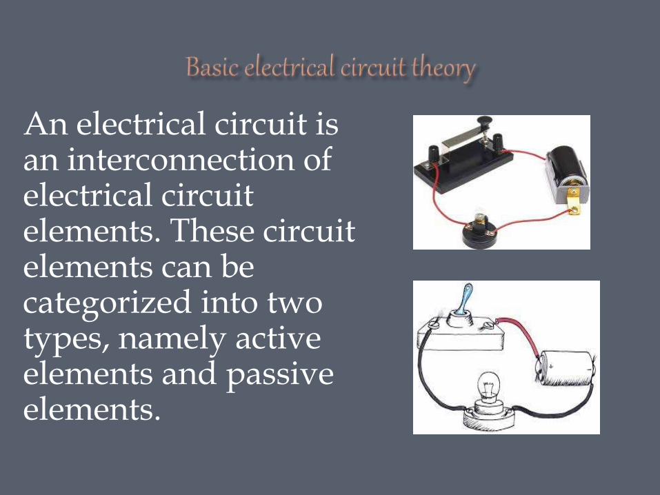
An electrical circuit is an interconnection of electrical circuit elements. These circuit elements can be categorized into two types, namely active elements and passive elements.
| Date post: | 29-Jan-2018 |
| Category: |
Engineering |
| Upload: | govind-giri |
| View: | 1,098 times |
| Download: | 6 times |
An electrical circuit is an interconnection of electrical circuit elements. These circuit elements can be categorized into two types, namely active elements and passive elements.
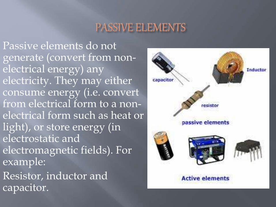
Passive elements do not generate (convert from non-electrical energy) any electricity. They may either consume energy (i.e. convert from electrical form to a non-electrical form such as heat or light), or store energy (in electrostatic and electromagnetic fields). For example:
Resistor, inductor and capacitor.
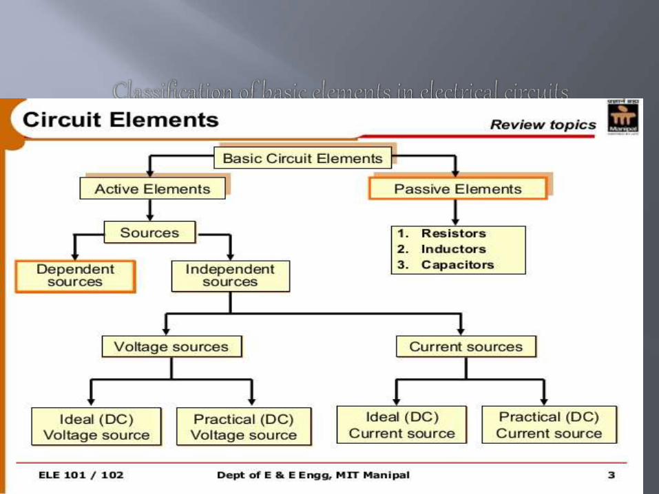
An Active Circuit Element is a component in a circuit which is capable of producing or generating energy. [Producing energy actually means converting non-electrical form of energy to an electrical form]. Active circuit elements are thus sources of energy (or simply sources) and can be categorized into voltage sources and the current sources.
Active elements are classified into two types:
1. Independent sources
2. Dependent sources
For an independent voltage source (or current source), the terminal voltage (or current) would
depend only on the loading and the internal source quantity, but not on any other circuit variable.
Independent sources are further classified into two types:
1. Independent current sources
2. Independent voltage sources
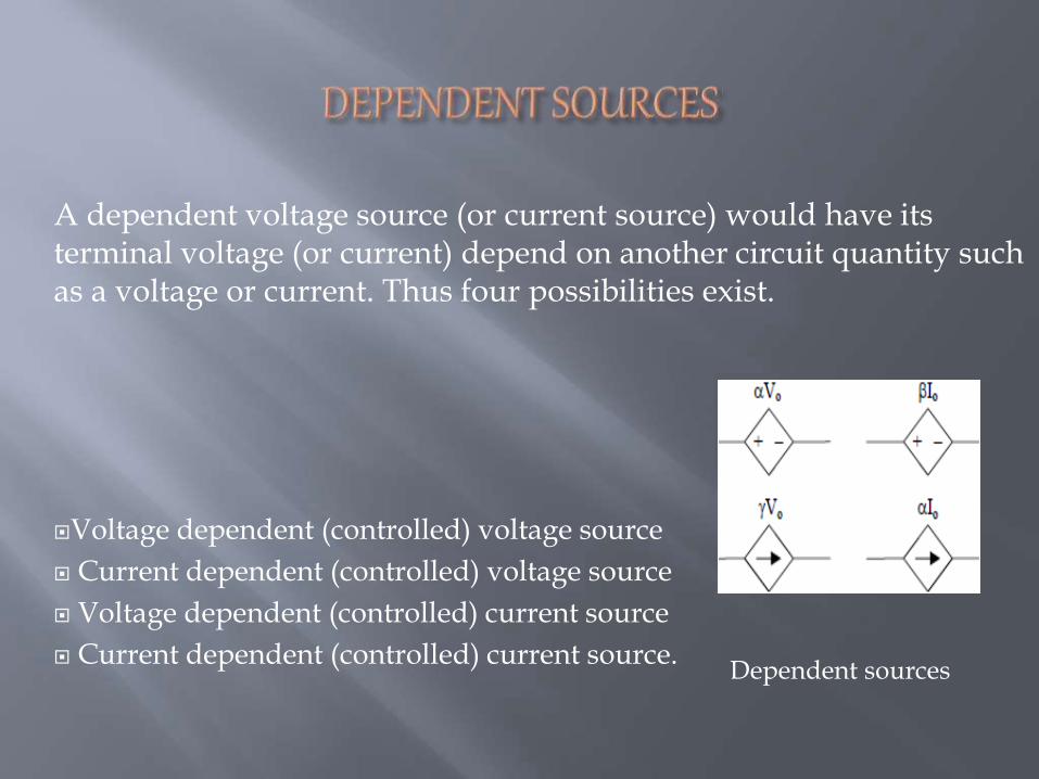
A dependent voltage source (or current source) would have its terminal voltage (or current) depend on another circuit quantity such as a voltage or current. Thus four possibilities exist.
Voltage dependent (controlled) voltage source
Current dependent (controlled) voltage source
Voltage dependent (controlled) current source
Current dependent (controlled) current source.Dependent sources
Node:- A simple node is a junction where any two elements are connected.
Junction:- A principle node or junction is a place where more than two elements are connected.
Branch:- It is the section between two nodes in the circuit.
Loop:- Loop is a close path made by branches in which current can flow. One loop may consist of number of meshes.
Mesh:- It is the loop which have no other connected loop.
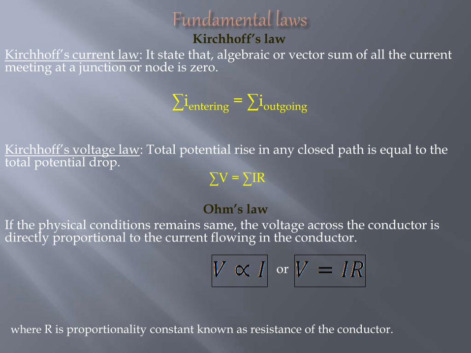
Kirchhoff’s lawKirchhoff’s current law: It state that, algebraic or vector sum of all the current meeting at a junction or node is zero.
∑ientering = ∑ioutgoing
Kirchhoff’s voltage law: Total potential rise in any closed path is equal to the total potential drop.
∑V = ∑IR
Ohm’s lawIf the physical conditions remains same, the voltage across the conductor is directly proportional to the current flowing in the conductor.
or
where R is proportionality constant known as resistance of the conductor.
On the basis of presence or absence of source
On the basis of direction of current
On the basis of seprability
On the basis of linearity
Active source:- if a network consist of an energy source then it is called an active network.
Passive source:- if a network doesn’t contained any energy sources then it is known as passive network.
1.Bilateral network:- it is the network whose characteristics of response does not depends the direction of current through the various elements in it.
2.Unilateral network:- it is the network whose characteristics of response depends the direction of current through the various elements in it.
1.Distributed network:- if the network elements such as resistance, inductance, and capacitance are not physically separated. Example- transmission lines.
2.Lumped network:- if the network elements are physically separated. Example- simple electrical network.
1. Linear network:- if the characteristics parameters such as inductance, resistance, capacitance are remains constant w.r.t. changing parameters like voltage and current known as linear network.
2. non linear network:- if the characteristics parameters are not remains constant with respect to changing parameters are known as non- linear networks.
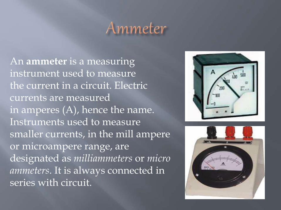
An ammeter is a measuring instrument used to measure the current in a circuit. Electric currents are measured in amperes (A), hence the name. Instruments used to measure smaller currents, in the mill ampere or microampere range, are designated as milliammeters or micro ammeters. It is always connected in series with circuit.
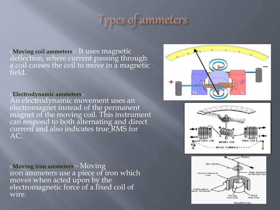
1.Moving coil ammeters:- It uses magnetic deflection, where current passing through a coil causes the coil to move in a magnetic field.
2.Electrodynamic ammeters:-An electrodynamic movement uses an electromagnet instead of the permanent magnet of the moving coil. This instrument can respond to both alternating and direct current and also indicates true RMS for AC.
3.Moving iron ammeters:- Movingiron ammeters use a piece of iron which moves when acted upon by the electromagnetic force of a fixed coil of wire.
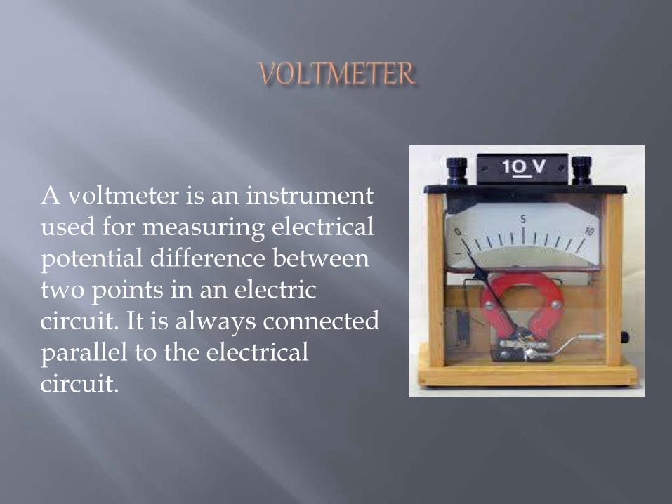
A voltmeter is an instrument used for measuring electrical potential difference between two points in an electric circuit. It is always connected parallel to the electrical circuit.
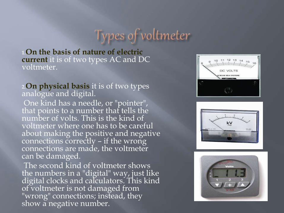
1.On the basis of nature of electric current it is of two types AC and DC voltmeter.
2.On physical basis it is of two types analogue and digital.One kind has a needle, or "pointer",
that points to a number that tells the number of volts. This is the kind of voltmeter where one has to be careful about making the positive and negative connections correctly – if the wrong connections are made, the voltmeter can be damaged.The second kind of voltmeter shows
the numbers in a "digital" way, just like digital clocks and calculators. This kind of voltmeter is not damaged from "wrong" connections; instead, they show a negative number.
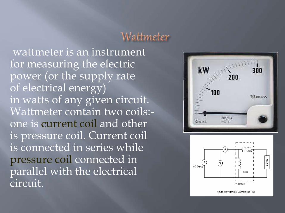
wattmeter is an instrument for measuring the electric power (or the supply rate of electrical energy) in watts of any given circuit. Wattmeter contain two coils:-one is current coil and other is pressure coil. Current coil is connected in series while pressure coil connected in parallel with the electrical circuit.
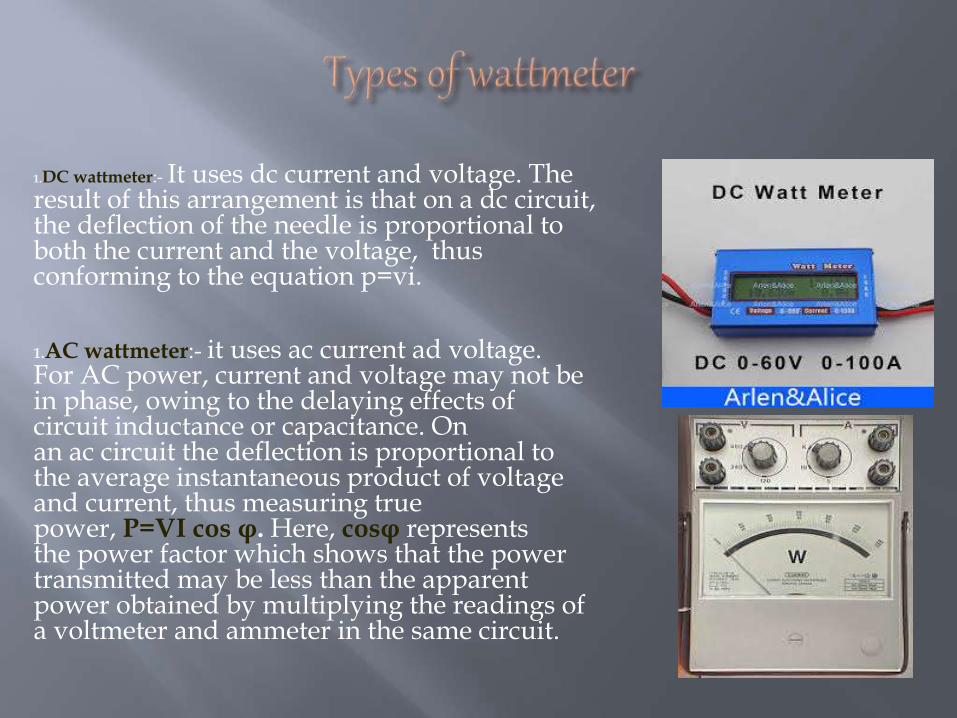
1.DC wattmeter:- It uses dc current and voltage. The result of this arrangement is that on a dc circuit, the deflection of the needle is proportional to both the current and the voltage, thus conforming to the equation p=vi.
1.AC wattmeter:- it uses ac current ad voltage. For AC power, current and voltage may not be in phase, owing to the delaying effects of circuit inductance or capacitance. On an ac circuit the deflection is proportional to the average instantaneous product of voltage and current, thus measuring true power, P=VI cos φ. Here, cosφ represents the power factor which shows that the power transmitted may be less than the apparent power obtained by multiplying the readings of a voltmeter and ammeter in the same circuit.
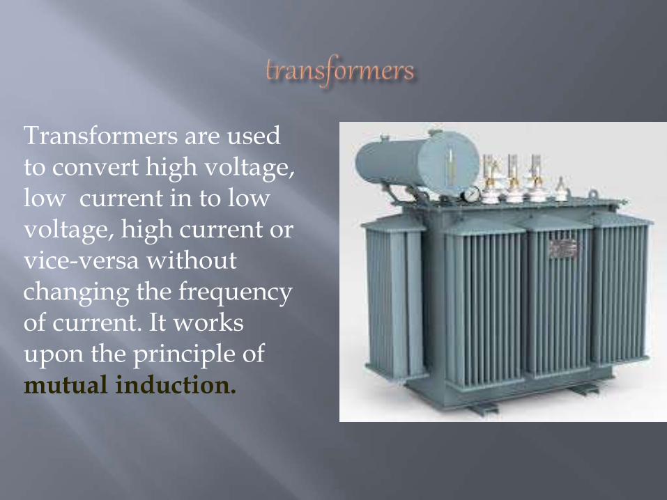
Transformers are used to convert high voltage, low current in to low voltage, high current or vice-versa without changing the frequency of current. It works upon the principle of mutual induction.
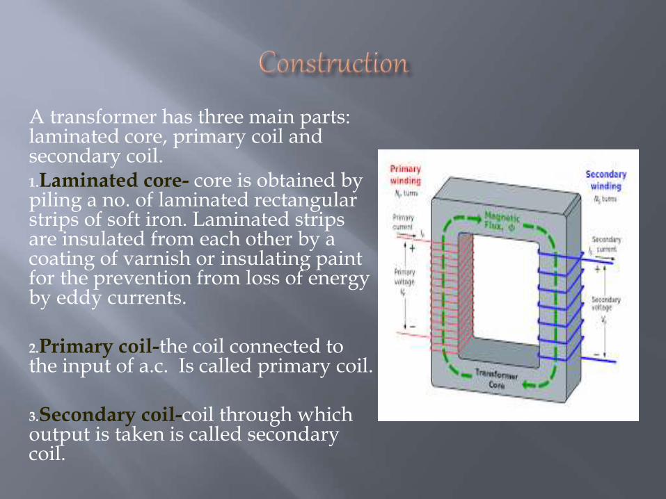
A transformer has three main parts: laminated core, primary coil and secondary coil.1.Laminated core- core is obtained by piling a no. of laminated rectangular strips of soft iron. Laminated strips are insulated from each other by a coating of varnish or insulating paint for the prevention from loss of energy by eddy currents.
2.Primary coil-the coil connected to the input of a.c. Is called primary coil.
3.Secondary coil-coil through which output is taken is called secondary coil.
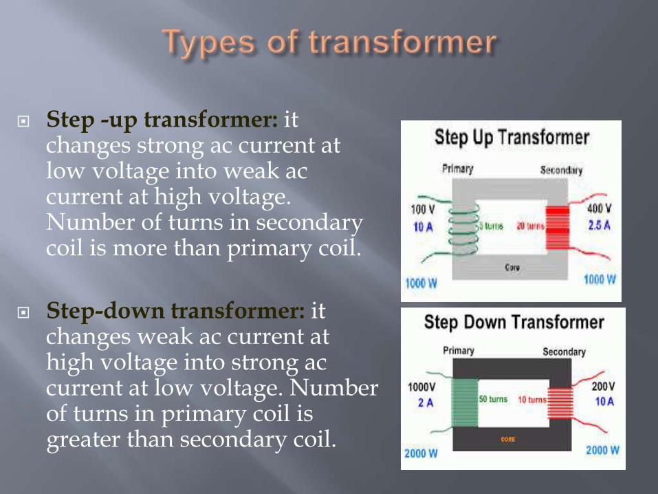
Step -up transformer: it changes strong ac current at low voltage into weak ac current at high voltage. Number of turns in secondary coil is more than primary coil.
Step-down transformer: it changes weak ac current at high voltage into strong ac current at low voltage. Number of turns in primary coil is greater than secondary coil.
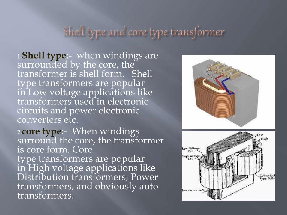
1.Shell type:- when windings are surrounded by the core, the transformer is shell form. Shelltype transformers are popular in Low voltage applications like transformers used in electronic circuits and power electronic converters etc.2.core type:- When windings surround the core, the transformer is core form. Core type transformers are popular in High voltage applications like Distribution transformers, Power transformers, and obviously auto transformers.


