54
Basic Electronics Jonathan Bachrach EECS UC Berkeley September 20, 2016

Basic Electronics
Jonathan Bachrach
EECS UC Berkeley
September 20, 2016
Last Time 1
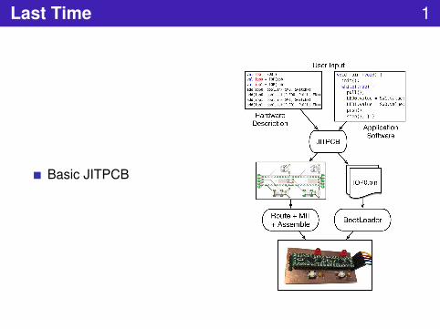
Basic JITPCB
Today 2
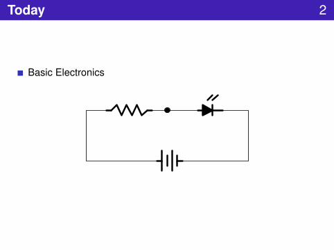
Basic Electronics

Circuit 3
Loop of conductive materialGraph of electrical componentsEdges are wiresVertices are componentsPoints on edges between on components are called nodes

Short Circuit 4
Loop from power source to itselfBeware as dangerous in heat and fireUse circuit breaker to prevent damage
5v

Open Circuit 5
Break in loopNo circuit at allBroken circuitCan detect with multimeter
5v
Charge 6
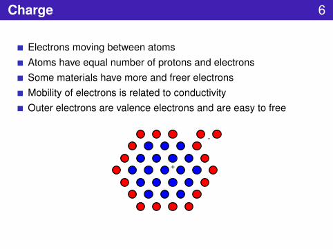
Electrons moving between atomsAtoms have equal number of protons and electronsSome materials have more and freer electronsMobility of electrons is related to conductivityOuter electrons are valence electrons and are easy to free
+
-
Electrostatic Force 7
Like charge repels and different charge attractsAmount of force depends on how far they are from each otherBasis for electric currentAlso causes lightning and sparks
Electronics 8
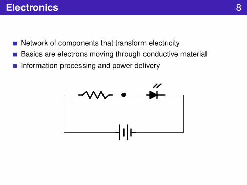
Network of components that transform electricityBasics are electrons moving through conductive materialInformation processing and power delivery

Basic Principles of Electricity 9
Voltage is difference in charge between two pointsCurrent is rate at which current is flowing at a pointResistance is degree to which a material slows down current
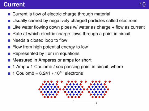
Current 10Current is flow of electric charge through materialUsually carried by negatively charged particles called electronsLike water flowing down pipes w/ water as charge + flow as currentRate at which electric charge flows through a point in circuitNeeds a closed loop to flowFlow from high potential energy to lowRepresented by I or i in equationsMeasured in Amperes or amps for short1 Amp = 1 Coulomb / sec passing point in circuit, where1 Coulomb = 6.241 ∗ 1018 electrons
I
+
- - -
+ +
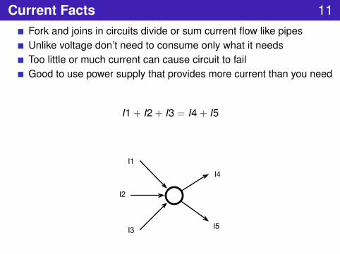
Current Facts 11Fork and joins in circuits divide or sum current flow like pipesUnlike voltage don’t need to consume only what it needsToo little or much current can cause circuit to failGood to use power supply that provides more current than you need
I1 + I2 + I3 = I4 + I5
I1
I2
I3
I4
I5

Voltage 12
Difference in electronic charge between two pointsMakes current flowLike water pressure in pipesNeed two points to define voltage
No absolute voltages only relative onesDifference in electric potential energy between two pointsReference is called “ground” and is set to zero volts
Represented by V in equationsMeasured in terms of energy per unit charge called Volts

Voltage Facts 13
All available voltage will be used in a circuitCan increase voltage by putting multiple power sources in series5V is common for embedded electronicsOperating voltage is desired voltage value circuit wantsOften circuits can run with higher voltage up to some limitComponents can be damaged with too little or too much voltageVoltage regulator takes range of voltage inputs and produces steadyvoltage outputCircuits can have multiple voltage inputs

Resistance 14
Ability to resist the flow of electrical chargeMaterials with high resistance are often used as insulatorsLike size of pipes in water pipes analogyCan regulate flow by increasing or decreasing resistanceProportion factor R, is known as the resistanceResistance has units of ohms (Ω)If voltage across the element is held constant, then increasing theresistance will limit the current going through the element

Ohm’s Law 15
Describes relationship between voltage, current and resistanceSays current is directly proportion to voltage
V = IR

Calculate Current from Voltage and Resistance 16
Calculate current through 50 ohm resistor using 5V
I = V/R = 5.0v/50Ω = 0.1amps = 100mA
5v
50 ohms
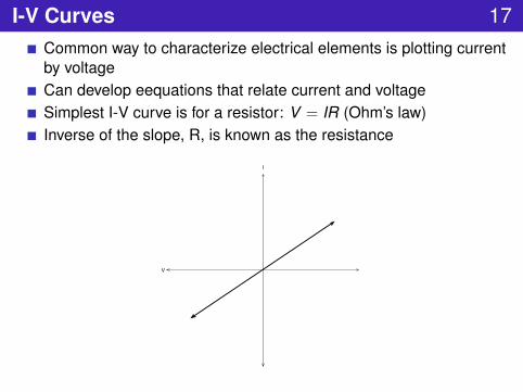
I-V Curves 17Common way to characterize electrical elements is plotting currentby voltageCan develop eequations that relate current and voltageSimplest I-V curve is for a resistor: V = IR (Ohm’s law)Inverse of the slope, R, is known as the resistance
V
I

Kirchoff Laws 18
Basically conservation of energySum of voltages in circuit loop adds to zeroSum of currents going in equal sum of currents going out
V
R1
R3R2

Simple Circuits 19
Node is point in circuit between components
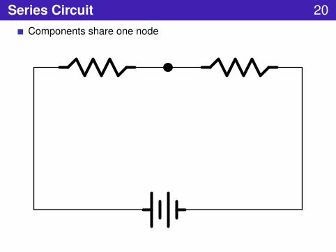
Series Circuit 20Components share one node

Parallel Circuit 21
Components share two nodes

Equivalent Series Circuit 22
Two resistors in seriesHarder for current to flow
R1 R2
V
R = R1 + R2

Equivalent Parallel Circuit 23
Two paths but same voltageDraws more current
R =R1 ∗ R2R1 + R2
R1 R2
V
1/R = 1/R1 + 1/R2
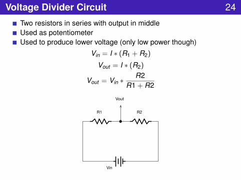
Voltage Divider Circuit 24
Two resistors in series with output in middleUsed as potentiometerUsed to produce lower voltage (only low power though)
Vin = I ∗ (R1 + R2)
Vout = I ∗ (R2)
Vout = Vin ∗ R2R1 + R2
R1 R2
Vin
Vout

Energy and Power 25
Components either consume or produce electric energyEnergy in JoulesVoltage is measure of energy that unit charge will dissipate whenflowing through deviceCurrent is number of couloumbs that flow through device in 1 secPower is rate at which energy is dissipatedPower (P) = joules per second = watts (W) = volts * ampsP = VIP = V 2/RP = I2R
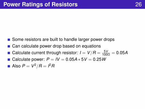
Power Ratings of Resistors 26
Some resistors are built to handle larger power dropsCan calculate power drop based on equationsCalculate current through resistor: I = V/R = 5V
100Ω = 0.05ACalculate power: P = IV = 0.05A ∗ 5V = 0.25WAlso P = V 2/R = I2R
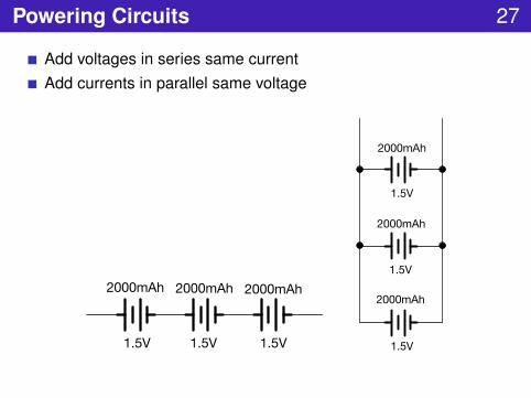
Powering Circuits 27
Add voltages in series same currentAdd currents in parallel same voltage
1.5V 1.5V1.5V
2000mAh 2000mAh 2000mAh1.5V
1.5V
1.5V
2000mAh
2000mAh
2000mAh
Calculating Power Needs 28
Calculate or measure current draw in circuitLook up battery capacity in Amp HoursDivide capacity by current drawBe conservative with capacity
Components 29
resistorpotentiometercapacitorswitchdiodeledtransistor

Resistors 30Slow down current – like rocks in riverFollow Ohm’s law, V = IRVariable resistors adjusted by force, temperature and knob calledpotentiometers
Afrank99 Junkyardsparkle

Different Resistance Values 31Fixed set of values and their powers of 10Values 10, 12, 15, 18, 22, 27, 33, 39, 47, 56, 68, and 82Color on them codes their value and their accuracyAccuracy as deviation like +-1, +-5, +-10Can create exact values by adding resistors in seriesResistors in parallel produce r1∗r2
r1+r2

Pull-up Resistor 32
Pulls value up to 5V in default stateWhen button depressed input goes to groundValue determines how much current flows when pressedR2 determines R1 so that Vin is high enough (10x)
Vout = VinR2
R1 + R2= 5 ∗ 10R
R + 10R= 5 ∗ 10
1 + 10≈ 5 ∗ 0.9
5v
button
R1
R2 MCU
inputpin
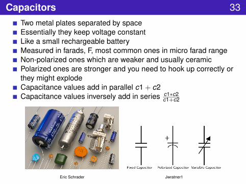
Capacitors 33Two metal plates separated by spaceEssentially they keep voltage constantLike a small rechargeable batteryMeasured in farads, F, most common ones in micro farad rangeNon-polarized ones which are weaker and usually ceramicPolarized ones are stronger and you need to hook up correctly orthey might explodeCapacitance values add in parallel c1 + c2Capacitance values inversely add in series c1∗c2
c1+c2
Eric Schrader Jwratner1

Uses of Capacitors 34
Filter out voltage changes for remove noiseDecoupling capacitors near ICsDebouncing buttonsEnergy storage
R
CI
Ktims

Capacitor Safety 35
Beware as capacitors hold onto charge and can be dangerous whenhigh voltage
Philippe Mertens
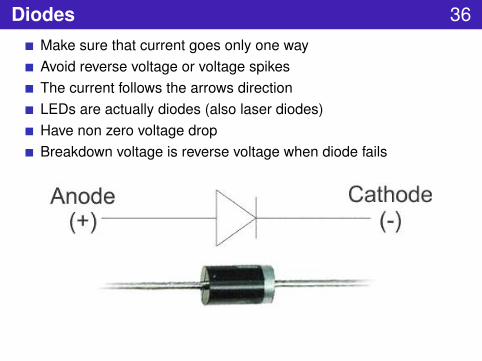
Diodes 36Make sure that current goes only one wayAvoid reverse voltage or voltage spikesThe current follows the arrows directionLEDs are actually diodes (also laser diodes)Have non zero voltage dropBreakdown voltage is reverse voltage when diode fails
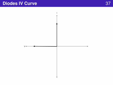
Diodes IV Curve 37
V
I

Real Diode IV Curve 38
V
I
Vf
Vb
Forward
ReverseBreakdown

Diode Uses 39
Used to prevent voltage spikes and reverse voltagesExample: Protect against batteries inserted incorrectlyExample: Prevent voltage spikes from solenoids + motorsCan rectify signalExample: change AC to DC
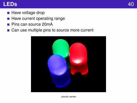
LEDs 40Have voltage dropHave current operating rangePins can source 20mACan use multiple pins to source more current
piccolo namek
Transistors 41-
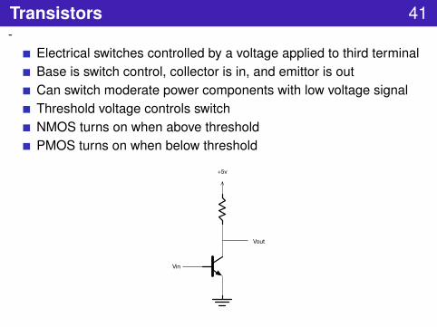
Electrical switches controlled by a voltage applied to third terminalBase is switch control, collector is in, and emittor is outCan switch moderate power components with low voltage signalThreshold voltage controls switchNMOS turns on when above thresholdPMOS turns on when below threshold
Vin
Vout
+5v
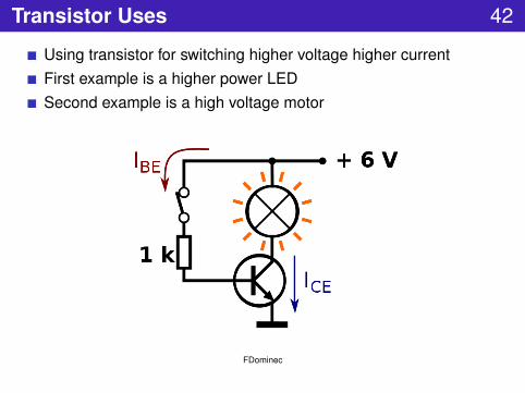
Transistor Uses 42
Using transistor for switching higher voltage higher currentFirst example is a higher power LEDSecond example is a high voltage motor
FDominec
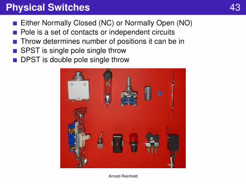
Physical Switches 43Either Normally Closed (NC) or Normally Open (NO)Pole is a set of contacts or independent circuitsThrow determines number of positions it can be inSPST is single pole single throwDPST is double pole single throw
Arnold Reinhold

Example Switches 44
SPST
SPDT
DPST
DPDTlainf

Multimeters and Measurements 45
Multimeters can measure resistance,voltage, current and continuityContinuity determines if two points areconnected – mode with beepResistance can be measured inunpowered circuit using Ω settingVoltage can be measured in poweredcircuit by putting probes in parallel withcircuitCurrent can be measured in seriesMake sure not to exceed current limitsof multimeterDebug using continuity and voltagechecks to compare against circuitdiagram

Multimeter Usage 46
mode functiondc volts measure voltage between probes
dc current measure current flowing through probesresistance measures resistance bteween probescontinuity checks if probed points are electrically connected
diodes measures voltage drop across a diode – continuity mode
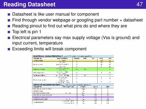
Reading Datasheet 47
Datasheet is like user manual for componentFind through vendor webpage or googling part number + datasheetReading pinout to find out what pins do and where they areTop left is pin 1Electrical parameters say max supply voltage (Vss is ground) andinput current, temperatureExceeding limits will break component
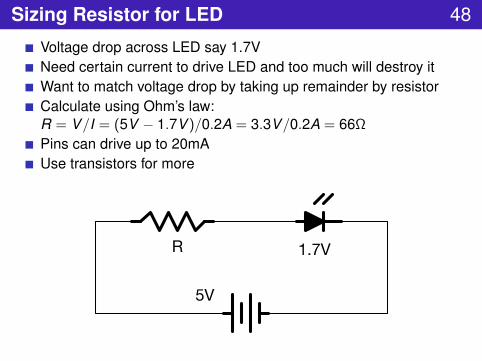
Sizing Resistor for LED 48
Voltage drop across LED say 1.7VNeed certain current to drive LED and too much will destroy itWant to match voltage drop by taking up remainder by resistorCalculate using Ohm’s law:R = V/I = (5V − 1.7V )/0.2A = 3.3V/0.2A = 66Ω
Pins can drive up to 20mAUse transistors for more
R
5V
1.7V

Potentiometer Usage 49
Want non-zero range of resistor values for reasonable currents butPotentiometer goes to zeroWhat circuit handles this?
5v
Electrical Safey 50
Current is what kills you not voltageCurrent above 15 to 100mA AC is lethalStill can get burned without getting electrocutedShut off things that shocked person before giving first aidDon’t allow yourself to become connection between a live wire andground especially through heartCircuits can be damaged by too much current or voltage
electrostatic discharge (ESD) will damage or destroy sensitive circuitcomponentspolarized components may explode if reversed

Logistics 51
Milling lab due ThursdaySoldering lab out Thursday

Next Time 52
Communication ProtocolsJITPCB Circuit Design


