67
Basic Embedded Systems Jonathan Bachrach EECS UC Berkeley September 2, 2016

Basic Embedded Systems
Jonathan Bachrach
EECS UC Berkeley
September 2, 2016

Last Time 1
Talked about StanzaLanguage used to write JITPCBUse C++ to write embedded apps running on circuit boards

Embedded Applications 2
Inputs -> Compute -> OutputsConcurrency realized on parallel hardwareBiggest challenge is mapping to limited hardwareDrivers: Size, Cost, Power and Reliability
Introduction to Embedded Systems by Edward Lee and Sanjit Seshia

Example Embedded Applications 3
Robot control – sensors and motorsLighting – LEDs etcElectronic music – synthesizers, effects and mixersIndustrial control – sensors and actuators

Real-time Embedded Applications 4
GoalsPerform tasks at given timesDon’t miss eventsLow latency
OptionsSchedule software to hardware orThrow hardware parallelism at the problem

Embedded Architecture 5Standard template with lots of parallelism:
MasterSlavesPeripheralsInterconnect
Periph.
Master IOP
I/O
Seq. In Data Bus Seq. Out
Periph.. . . Periph.
Slave IOP
I/O
Seq. In Data Bus Seq. Out
Periph.. . .
. . . . . .
SOB
Host System

CPU 6
Program StorageData MemoryALUPC
ALUIMEM DMEM
pc
instaddr
rdat
wdat

CPU with Registers 7RISC – Reg to Reg
load literalload from memory to registerstore to memory from registerand/or from reg x reg to regjump to address in registerinterrupt to address in memory
ALUIMEM DMEM
pc
inst
rdat
addrREGsDecode
wdat

Numeric Data Types 8
Floating point – expensive but big dynamic rangeFixed point – cheap but tedious to manage
2 9 8 5 6 5 5 9
decimal point

ISA and Realization 9Instruction Set Architecture (ISA) – Spec – ARM, x86Realization – same code but different speed/area/power – CortexM4, Corei7
Category Name Fmt RV32I Base Category Name RV mnemonicLoads Load Byte I LB rd,rs1,imm CSR Access Atomic R/W CSRRW rd,csr,rs1
Load Halfword I LH rd,rs1,imm Atomic Read & Set Bit CSRRS rd,csr,rs1 Load Word I LW rd,rs1,imm Atomic Read & Clear Bit CSRRC rd,csr,rs1
Load Byte Unsigned I LBU rd,rs1,imm Atomic R/W Imm CSRRWI rd,csr,imm Load Half Unsigned I LHU rd,rs1,imm Atomic Read & Set Bit Imm CSRRSI rd,csr,imm
Stores Store Byte S SB rs1,rs2,imm Atomic Read & Clear Bit Imm CSRRCI rd,csr,imm Store Halfword S SH rs1,rs2,imm Change Level Env. Call ECALL
Store Word S SW rs1,rs2,imm Environment Breakpoint EBREAK
Shifts Shift Left R SLL rd,rs1,rs2 Environment Return ERET Shift Left Immediate I SLLI rd,rs1,shamt Trap Redirect to SupervisorMRTS
Shift Right R SRL rd,rs1,rs2 Redirect Trap to Hypervisor MRTH Shift Right Immediate I SRLI rd,rs1,shamt Hypervisor Trap to Supervisor HRTS Shift Right Arithmetic R SRA rd,rs1,rs2 Interrupt Wait for Interrupt WFI Shift Right Arith Imm I SRAI rd,rs1,shamt MMU Supervisor FENCE SFENCE.VM rs1
Arithmetic ADD R ADD rd,rs1,rs2 ADD Immediate I ADDI rd,rs1,imm
SUBtract R SUB rd,rs1,rs2
Load Upper Imm U LUI rd,imm Add Upper Imm to PC U AUIPC rd,imm Category Name Fmt RVC RVI equivalent
Logical XOR R XOR rd,rs1,rs2 Loads Load Word CL C.LW rd′,rs1′,imm LW rd′,rs1′,imm*4 XOR Immediate I XORI rd,rs1,imm Load Word SP CI C.LWSP rd,imm LW rd,sp,imm*4
OR R OR rd,rs1,rs2 Load Double CL C.LD rd′,rs1′,imm LD rd′,rs1′,imm*8OR Immediate I ORI rd,rs1,imm Load Double SP CI C.LDSP rd,imm LD rd,sp,imm*8
AND R AND rd,rs1,rs2 Load Quad CL C.LQ rd′,rs1′,imm LQ rd′,rs1′,imm*16AND Immediate I ANDI rd,rs1,imm Load Quad SP CI C.LQSP rd,imm LQ rd,sp,imm*16
Compare Set < R SLT rd,rs1,rs2 Stores Store Word CS C.SW rs1′,rs2′,imm SW rs1′,rs2′,imm*4 Set < Immediate I SLTI rd,rs1,imm Store Word SP CSS C.SWSP rs2,imm SW rs2,sp,imm*4
Set < Unsigned R SLTU rd,rs1,rs2 Store Double CS C.SD rs1′,rs2′,imm SD rs1′,rs2′,imm*8 Set < Imm Unsigned I SLTIU rd,rs1,imm Store Double SP CSS C.SDSP rs2,imm SD rs2,sp,imm*8
Branches Branch = SB BEQ rs1,rs2,imm Store Quad CS C.SQ rs1′,rs2′,imm SQ rs1′,rs2′,imm*16 Branch ≠ SB BNE rs1,rs2,imm Store Quad SP CSS C.SQSP rs2,imm SQ rs2,sp,imm*16 Branch < SB BLT rs1,rs2,imm Arithmetic ADD CR C.ADD rd,rs1 ADD rd,rd,rs1 Branch ≥ SB BGE rs1,rs2,imm ADD Word CR C.ADDW rd,rs1 ADDW rd,rd,imm
Branch < Unsigned SB BLTU rs1,rs2,imm ADD Immediate CI C.ADDI rd,imm ADDI rd,rd,imm Branch ≥ Unsigned SB BGEU rs1,rs2,imm ADD Word Imm CI C.ADDIW rd,imm ADDIW rd,rd,imm
Jump & Link J&L UJ JAL rd,imm ADD SP Imm * 16 CI C.ADDI16SP x0,imm ADDI sp,sp,imm*16 Jump & Link Register UJ JALR rd,rs1,imm ADD SP Imm * 4 CIW C.ADDI4SPN rd',imm ADDI rd',sp,imm*4
Synch Synch thread I FENCE Load Immediate CI C.LI rd,imm ADDI rd,x0,imm Synch Instr & Data I FENCE.I Load Upper Imm CI C.LUI rd,imm LUI rd,imm
System System CALL I SCALL MoVe CR C.MV rd,rs1 ADD rd,rs1,x0 System BREAK I SBREAK SUB CR C.SUB rd,rs1 SUB rd,rd,rs1
Counters ReaD CYCLE I RDCYCLE rd Shifts Shift Left Imm CI C.SLLI rd,imm SLLI rd,rd,imm ReaD CYCLE upper Half I RDCYCLEH rd Branches Branch=0 CB C.BEQZ rs1′,imm BEQ rs1',x0,imm
ReaD TIME I RDTIME rd Branch≠0 CB C.BNEZ rs1′,imm BNE rs1',x0,imm ReaD TIME upper Half I RDTIMEH rd Jump Jump CJ C.J imm JAL x0,imm ReaD INSTR RETired I RDINSTRET rd Jump Register CR C.JR rd,rs1 JALR x0,rs1,0
ReaD INSTR upper Half I RDINSTRETH rd Jump & Link J&L CJ C.JAL imm JAL ra,imm Jump & Link Register CR C.JALR rs1 JALR ra,rs1,0System Env. BREAK CI C.EBREAK EBREAK
CRR CII CSSS CIWSB CLU CSUJ CB
CJRISC-V Integer Base (RV32I/64I/128I), privileged, and optional compressed extension (RVC). Registers x1-x31 and the pc are 32 bits wide in RV32I, 64 in RV64I, and 128 in RV128I (x0=0). RV64I/128I add 10 instructions for the wider formats. The RVI base of <50 classic integer RISC instructions is required. Every 16-bit RVC instruction matches an existing 32-bit RVI instruction. See risc.org.
32-bit Instruction Formats 16-bit (RVC) Instruction Formats
SRAI{W|D} rd,rs1,shamtADD{W|D} rd,rs1,rs2ADDI{W|D} rd,rs1,immSUB{W|D} rd,rs1,rs2
Optional Compressed (16-bit) Instruction Extension: RVC
SRL{W|D} rd,rs1,rs2SRLI{W|D} rd,rs1,shamtSRA{W|D} rd,rs1,rs2
S{D|Q} rs1,rs2,imm
SLL{W|D} rd,rs1,rs2SLLI{W|D} rd,rs1,shamt
L{D|Q} rd,rs1,imm
L{W|D}U rd,rs1,imm
Free & Open Reference Card ①
+RV{64,128}Base Integer Instructions: RV32I, RV64I, and RV128I RV Privileged Instructions
RISCV 10
Berkeley’s very own ISA: riscv.orgOpen Source HW/SW interfaceGCC + Linux + ...Sample implementationsSiFive: sifive.com

Embedded DSPs 11
limited memorysimple pipeliningcompressed instructionsDSP instructionsfloating point hardware

STM32L432 1232 bit processor80MHz clock speedfloating point hardwaredebug support
ARM

Compilers and Linkers 13
Compiler translates C into object filesLinker combines object files into app binaryApps are in Elf or Hex format
gcc linker.obj .hexC elf2hex.elf

Debug Support 14
JTAG portProgrammingSet break pointsGet stateStandard interface like OpenOCDLinker also produces source information fileSource debug through GDB or Eclipse

Memory 15
Random access like arrayPersistance: Volatile or Non-VolatileCapacity: Size and WidthSpeed: Latency and ThroughputPower: Efficiency
Mem
r/w
addr
wdat
rdat

Volatile RAM 16
Name SRAM DRAMComplexity Simple Refresh
Area Big DenseCost Expensive Cheap
Speed Fast Medium
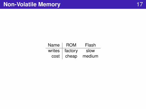
Non-Volatile Memory 17
Name ROM Flashwrites factory slow
cost cheap medium

Flash 18
Put onto chips as well as disksOrganized into pages (e.g., 2KB)Erase only on pagesLimited R/W/X protectionCan store either Data or Code

Memory Protection 19
can control access to pages of memoryprotects against certain crashesSTM32L432 has crude sys with a few regions and modes

Memory Map 20
Address SpaceSRAM and FlashMemory mapped peripherals – timers, gpio, uarts,Register files

STM32L432 Memory Map 21

Memory Mapped Peripherals 22
Example TimerStatus registers: valueControl registers: up/down, reset, period
Counter
up/dn
reset
period
value
up/dn
reset
period
value
0xfff0003
0xfff0002
0xfff0001
0xfff0000
…
…

Jump Table – Vectors 23
int2
int1
int0
start
…
…
int0 handler
app
…
…

Stacks 24
stack pointer usually put in registerused for function calling – stack framestack overflow
R.S. Shaw
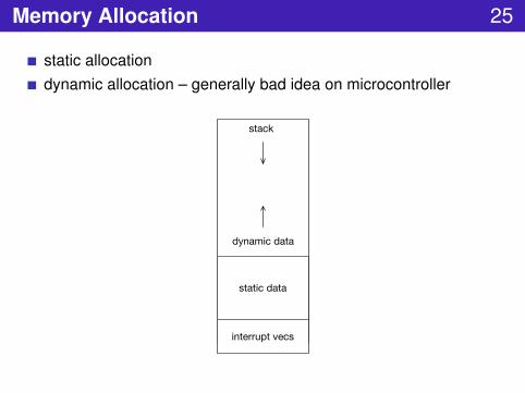
Memory Allocation 25
static allocationdynamic allocation – generally bad idea on microcontroller
static data
interrupt vecs
dynamic data
stack

Dynamic Allocation 26
Malloc or C++ newStack allocation – dynamic extent
static data
interrupt vecs
dynamic data
stack

DMA 27
direct memory accessmemory mapped peripheralhardware device takes over memory transferoffloads CPU and more efficientoverlap memory transfers with compute
CPU Per0 Per1
MemDMA

Programming through JTAG 28
Install App + Data into flashInitialize Start + Interrupt Vectors
app
interrupt vecs
start pc + sp
static data
…
flash map

Booting Process 29
Power onJump through start Vector and initialize stack pointerBoot modes say where to boot from – can be based on pinReset Pin causes reboot
app
interrupt vecs
start pc + sp
static data
…
flash map
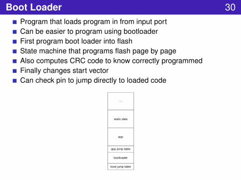
Boot Loader 30Program that loads program in from input portCan be easier to program using bootloaderFirst program boot loader into flashState machine that programs flash page by pageAlso computes CRC code to know correctly programmedFinally changes start vectorCan check pin to jump directly to loaded code
app jump table
bootloader
app
boot jump table
static data
…

Low Power 31
Sleep – CPU shut down but periphs working – wakeup on interruptLow Power – Slow down CPU to say 2MHzLow Power Sleep – Same staying in low power upon wakeupStop 0, 1, 2 – Retain SRAM contents but lowest powerStandby – turn off but passively assert I/Os

Peripherals 32
timersDMArandom number generatorCRCwatchdog timerI/O

Timers 33
count up/downperiodprescaler – slows down clockraise interrupt upon hitting min or maxautomatic reload

Real Time Clock 34
returns time in standard formatscorrection for leap years etcdigital calibration to overcome crystal imperfectionbackup registers for user data

Watchdog Timer 35
must be poked every so oftenotherwise resets microcontroller

I/O 36microcontrollers have a bunch of peripherals on boardmany peripherals talk to outside through pinscan map peripherals to pins through cross bar

GPIO 37
attached to pinsmemory mappedcan be configured as input or outputcurrent limits on pins (e.g., 18mA)when configured as input – only one driver at a time
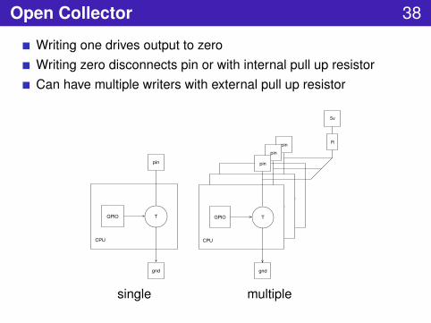
Open Collector 38
Writing one drives output to zeroWriting zero disconnects pin or with internal pull up resistorCan have multiple writers with external pull up resistor
TGPIO
gnd
pin
CPU
TT
pinpin
TGPIO
gnd
pin
CPU
5v
R
single multiple

Tristate 39
can be in one of three states: on/off or disconnectedunlike open collector can drive one

Serial 40
de/serializes bits of bytes over single or few wiresUART: baud rate, start bit, data bits, parity bit, stop bitsUSB JTAG I2C SPI ...
data bits
start bit stop bit
parity bit

Bus 41
shared wiresless expensivefewer wiresneed MAC to arbitrate
master slave0 slave1

MAC 42
master / slaveTDMAtoken ringbus arbiter hardwareCSM carrier sense multiple access
slave0 master slave1cs0 cs1

Bus Examples 43
name mac width controlSPI master/slave 4 wires select linesI2C master/slave 2 wires addresses
CAN arbitration x wires addresses
more details to come
slave0 master slave1cs0 cs1
clkmiso
mosi

I2C 44
two wires: clk and datamaster initiates all communicationslave addresses used to determine message source/destinationslaves listen for their addresses and then commandhardware supports lowest level state machine and clocking
slave0 master slave1
clkdat

Analog In/Out 45
Analog OutDACexample: audiobits precisionoptional timer + DMA
Analog InADCexample: potentiometerbits precisioncan attach a voltage trigger

PWM 46
analog out approximationduty cycle and frequencyoften used for driving motor
Zureks

Interrupts 47
break from normal program flowinterrupt handlersimple way to map concurrency onto hardware
Interrupt Types 48
hardware interrupts – external thingsoftware interrupts – instruction or by writing to memory registerexception – detects a fault

Interrupts 49
enable/disableprioritiesinterrupt vectors

Atomicity 50
interrupts happen between any instructionssome regions need to be atomicexample is copying multiword dataunderstand all interleavings

Atomicity Example 51
writer one
count = double_value;
count0 = double_value0;
// interrupt happens here
count1 = double_value1;
writer two
count = count + 1;

Atomicity Solution 52
writer one
disable_interrupts();
count = double_value
enable_interrupts();
writer two
disable_interrupts();
count = count + 1;
enable_interrupts();

Interrupt Controller 53
interrupt vectorsinterrupt vector table – computes interrupt vector table addressnestingprioritiesmaskingprocessor state savingrestore interrupt entry

Interrupt Handler 54
disable interruptspush pc, psrbranch to int vecsave regs useddo handlingpop regs usedpop pc, psrenable interrupts
Interrupt Handler on STM32L432 55
hardware support fordisabling and enabling interruptssaving and restoring registersmore features as well
more details later

External Interrupts 56
edge triggered (rising or falling or both) or level triggeredn channels detecting particular event on pindetects pulses shorter than clock periodless overhead than pollingresetwakeup
Interrupt Issues 57
don’t want to lose any eventskeep code in interrupts to minimumuse prioritiesevents happen at much slower frequency relative to cpu

Quadrature Encoder 58
determines radial position of shaftcounts transitions on two pinscould write a routine to poll pins and countbetter way is to assign interrupts to pinshandler then runs state machine which countsoutput is position value
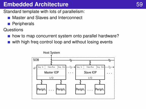
Embedded Architecture 59Standard template with lots of parallelism:
Master and Slaves and InterconnectPeripherals
Questionshow to map concurrent system onto parallel hardware?with high freq control loop and without losing events
Periph.
Master IOP
I/O
Seq. In Data Bus Seq. Out
Periph.. . . Periph.
Slave IOP
I/O
Seq. In Data Bus Seq. Out
Periph.. . .
. . . . . .
SOB
Host System

Example System 60
two motor robot armi2c bus between one master and two slaves
Arm mechanism. Master board. Motor board.
System of three boards.

Robot Arm Embedded Architecture 61
one master for outer control loopone slave for each motori2c to communicate master to slave
master slave0 slave1
motor0 motor1
e0 e1 fi fo e0 e1 fi fo
i2c
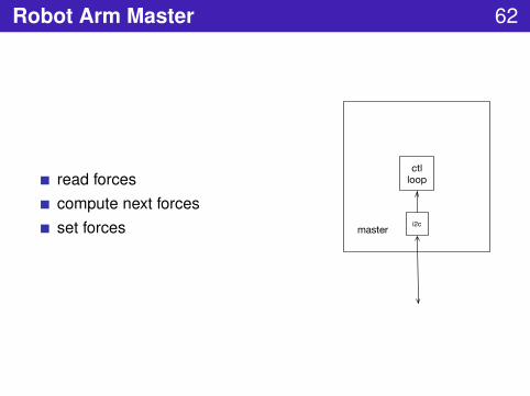
Robot Arm Master 62
read forcescompute next forcesset forces i2c
ctlloop
master

Robot Arm Slave 63
input force from masterquad encoder measuring motor posforce in (fi) measuring impedanceforce out (fo) setting motor driveoutput force to master
motor0
e0 e1 fi fo
adc pwmint0 int1
i2c
enc ctlloop
slave0

Next Time 64
Cover simple C++Dive into mBED libraryGive more concrete embedded examples

Reminders 65
Section Friday 3-4p in Jacobs 220Get Maker PassStart thinking partners

References 66
Digital Design and Computer Architecture: David Harris and SarahHarrisSTM32L432 Data SheetNucleo32 L432https://developer.mbed.org/platforms/ST-Nucleo-L432KC/
Introduction to Embedded Systems: A Cyber-Physical SystemApproach: Edward Lee and Sanjit Seshia


