69
Basic Hydraulics 17 June 2015 1

Basic Hydraulics
17 June 2015 1

17 June 2015 2
Hydraulics is the science of forces and movements transmitted by means
of liquids.

Fluid transport systems
Fluid power systems
17 June 2015 3
FLUID TECHNOLOGY
17 June 2015
. • FLUID POWER CONCEPT
4
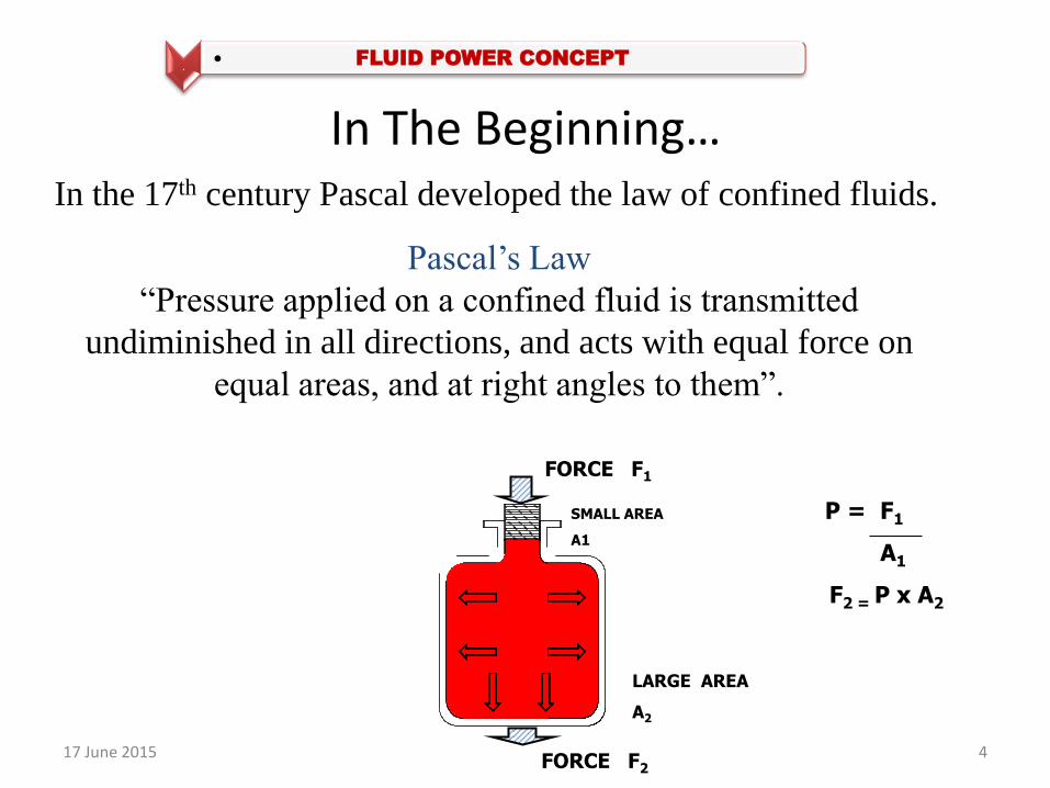
In The Beginning… In the 17th century Pascal developed the law of confined fluids.
Pascal’s Law
“Pressure applied on a confined fluid is transmitted
undiminished in all directions, and acts with equal force on
equal areas, and at right angles to them”.
FORCE F1
SMALL AREA
A1
P = F1
A1
F2 = P x A2
LARGE AREA
A2
FORCE F2

HYDROSTATICS
F1 = 1 Kg
A1 = 1 Cm2
P = F1 = 1 Kg
A1 1 Cm2
= 1 Kg / Cm2
( Same Pressure P )
A2 = 10 Cm2
F2 = P x A2
= 1 x 10
= 10 Kg

17 June 2015
PASCAL’S Law
6

LIQUID AT
HIGH VELOCITY
HYDRODYNAMICS

Fig: Hydraulic press
Fig: Hydraulic lift table
Fig: Hydraulic disc brakes
Fig: Excavator
17 June 2015 8
Hydraulic System Applications
TANK
PUMP PRIME
MOVER
PRESSURE CONTROL
CONTROL
VALVES
ACTUATOR
FILTER
Electrical Energy to
Mechanical Energy
Mechanical Energy
to Hydraulic
Energy
Hydraulic Energy
to Mechanical
Energy
17 June 2015 9
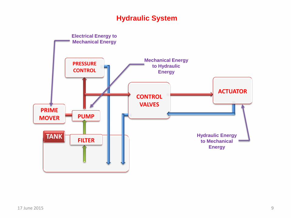
Hydraulic System

1. Power pack
a) Tank / reservoir
b) Oil
c) Filters
d) Strainers
2. Control valves
a) Direction
b) Pressure
c) Flow
e) Prime movers
f) Pumps
g) Oil level and Temperature indicators
h) Heat exchangers
4. Accessories
a) Accumulators
b) Pressure gauges
c) Temperature gauges
17 June 2015 10
Hydraulic System Components
3. Actuators a) Cylinders
b) Motors

Technical data Capacities - litres Type of pump ( Fixed / Variable displacement) Displacement V g max cm³ Operating pressure p max bar El. motor power P kW
. • POWER PACK
11
Elements Tank Oil Filters & Strainers Breathers Pump Electrical Motor Heat Exchangers Oil level indicators Pressure and Temperature gauges

Tank / reservoir
Symbol
Hydraulic Oil
Temperature range: -54° C to 135° C
NAS class, ISO class
Viscosity, Viscosity Index
Compressibility
Foaming

Beta ratio (β) = Upstream particle count / Downstream particle count.
Symbol
Hydraulic Filters

Breathers and Strainers
1. Air Filtration
2. Dehumidification Symbol

Types of Filters
Suction Filter • Located in the suction line of the pump
• Only filtered oil entered the system
• Grade of filtration is 60 µm – 100 µm
• Purely to protect the pump from contamination
• That is why suction filters are equipped with by-pas valves
• Can also be used ahead of the pump as a coarse filter

Types of Filters
Pressure Filter
• Installed in the pressure line of the hydraulic system ahead of the device which are
sensitive to dirt e.g. at the pressure port of the pump ahead of valves or flow control
valves
• Since this filter is subjected to maximum pressure, it must be of robust design
• Should not have a by-pass but have a contamination indicator
• Operating pressure up to 420 bar
• Grade of filtration 3 µm– 5 µm
• Requires a pressure tight housing and contamination indicator
• The effectiveness of the filter is checked be the contamination indicator

Types of Filters
Return Filter • Installed in the return line
• Cheaper than the high pressure filter
• Operating pressure up to max. 30 bar
• Grade of filtration 10 µm – 25 µm
Main stream Filtering
Suction filter : Pr. Difference = 0.05 to 0.1 bar at operating temperature
Pressure filter : Pr. Difference = 1 to 1.5 bar at operating temperature
Return filter: Pr. Difference = 0.5 bar at operating temperature

Principle – What is Pump ?
Pump is a Source of Power
Primary Function is to develop
flow not pressure
•HYDRAULIC PUMPS

19
Hydraulic Pumps
(i) Non-positive displacement or Hydrodynamic
pumps
• Low pressure high flow applications
(ii) Positive displacement or Hydrostatic pumps
• High pressure low flow applications

Centrifugal Pump
17 June 2015 20
Non- Positive Displacement Pump

17 June 2015 21

17 June 2015
POSITIVE DISPLACEMENT PUMPS
PISTON
1.Axial Design a) Bent axis type (F/V) b) Swash plate type (F/V) 2. Radial Design
GEAR
1. External Gear 2. Internal Gear 3. Gerotor 4. Lobe 5. Screw
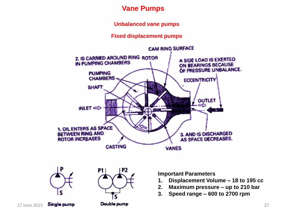
VANE
1. Unbalanced a) Fixed Displacement
b) Variable Displacement
2. Balanced (Fixed)
Volumetric efficiency 1.Gear pumps – 80% to 90%
2.Vane pumps - 82% to 92%
3.Piston pumps - 90% to 98%
22
Classification of Positive Displacement Pumps

17 June 2015
Fig: External gear pumps
Important Parameters
1. Displacement Volume – 0.2 to 200 cc
2. Maximum pressure – up to 300 bar
3. Speed range – 500 to 6000 rpm
23
Gear Pumps

17 June 2015 24

17 June 2015
Important Parameters
1. Displacement Volume – 0.2 to 200 cc
2. Maximum pressure – up to 300 bar
3. Speed range – 500 to 6000 rpm
Internal gear pumps
25
17 June 2015
Unbalanced vane pumps
Important Parameters
1. Displacement Volume – 18 to 195 cc
2. Maximum pressure – up to 210 bar
3. Speed range – 600 to 2700 rpm
Fixed displacement pumps
27
Vane Pumps

17 June 2015 28

Variable Displacement Pump
17 June 2015 29

17 June 2015
1. Fixed displacement
Important Parameters
1. Displacement Volume – 18 to 1000 cc
2. Maximum pressure – up to 400 bar
3. Speed range – 600 to 6000 rpm
30
Axial Piston Pump – Bent Axis Design

17 June 2015 31

Axial Piston Pump – Swash Plate Design
17 June 2015 32

17 June 2015 33

17 June 2015
Important Parameters
1. Displacement Volume – 500 cc
2. Maximum pressure – up to 700 bar
3. Speed range – 1000 to 3400 rpm 34
Radial Piston Pump
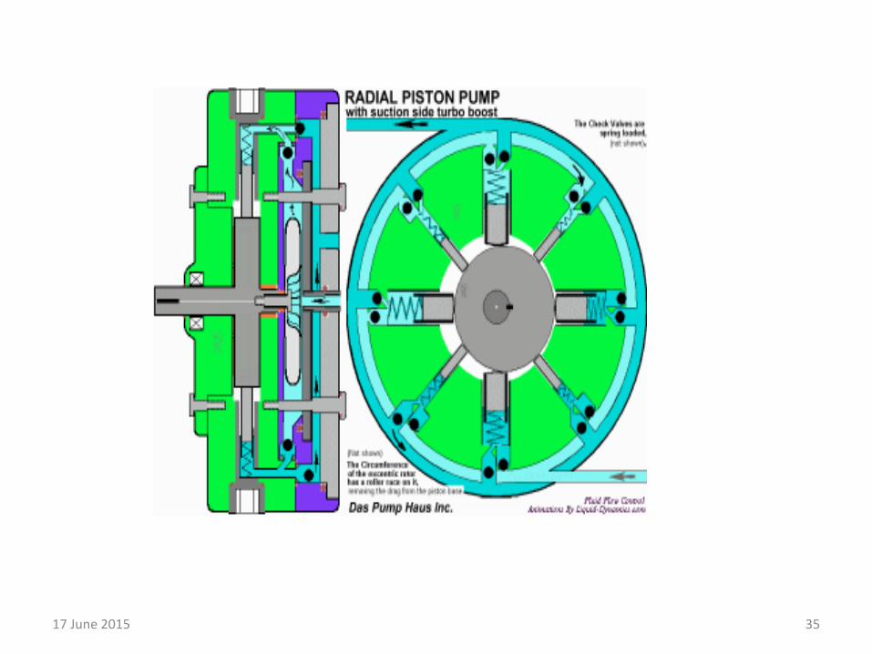
17 June 2015 35

17 June 2015
1. Non-return Valve (NCV)
2. Flow control valve (FCV)
3. Pressure control valves (PCV)
4. Direction control valves (DCV)
36
Control Valves

2. Double acting 1. Single acting
17 June 2015 37
Actuators

Accumulator It is the Energy storage device which is used when
The pump cannot meet the extremes of fluid demand in the circuit
Supply circuit needs to respond more quickly to any temporary demand
Bladder type
. • Accessories
17 June 2015 38

17 June 2015 39
Heat Exchanger

Oil Level Indicators
Oil Temperature Indicators
17 June 2015 40

Simple open-loop open-center circuit
cylinder
4-way, 3 position valve
Pressure relief valve
Fixed displacement pump
filter
Fluid tank or reservoir
Actuating solenoid
Spring return

Fluid power symbols
Main Line
Pilot Line
Drain Line
Lines Crossing
Lines Joining
Variable
Temperature
Pneumatic
Hydraulic
Flexible line

Plugged Port
Vented Pressurized
Below fluid level Above fluid level
Accumulator
Heat Exchanger
Filter or Strainer
Lubricator
Single Acting
Cylinder
Double Acting
Cylinder
Double Acting
Double rod
Cylinder

Double Acting Cylinder
with Cushion
Double Acting Cylinder
with adjustable Cushion
Pressure Intensifier
Spring
Manual
Push Button
Lever
Pedal or Treadle
Mechanical
Detent
Pressure Compensated
Solenoid
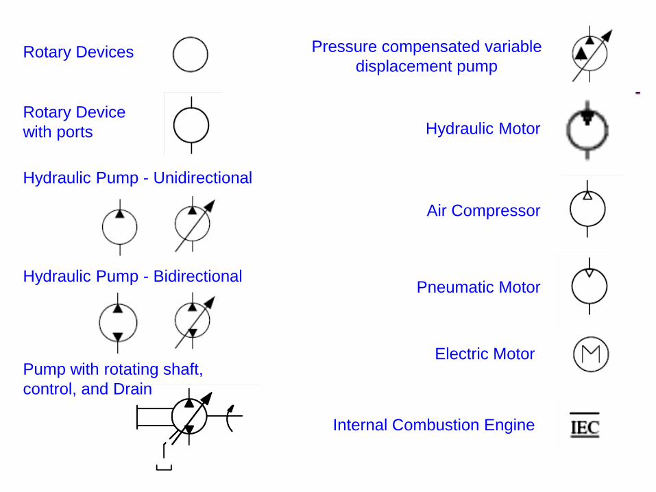
Rotary Devices
Rotary Device
with ports
Hydraulic Pump - Unidirectional
Hydraulic Pump - Bidirectional
Pump with rotating shaft,
control, and Drain
Pressure compensated variable
displacement pump
Hydraulic Motor
Air Compressor
Pneumatic Motor
Electric Motor
Internal Combustion Engine

Pressure Indication
Temperature Indication
Flow Meter
Envelopes or Positions
One Two Three
Ports
Two Two Four
Three Positions, Four Ports (4/3)
Shut Off
Check Valve
Pilot operated Check Valve
Pilot to open
Pilot to close
Two position, Two port, (2/2) DCV

2/2 DCV
4/3 DCV
4/3 DCV, Left actuated
4/3 DCV, Right actuated
Infinite position
Pressure Relief Valve
Pressure Reducing Valve
Flow Control Valve with
bypass check valve

Hydraulic Fluids
The hydraulic fluids used must fulfill the following properties:
• Pressure transfer
• Lubrication of moving parts
• Cooling
• Corrosion protection
• Scuff removal
• Signal transmission

Types of Hydraulic Oils
• Hydraulic Oils are divided according to their characteristic and
composition into three classes:
1. Hydraulic oil HL
2. Hydraulic oil HLP
3. Hydraulic oil HV


Characteristics of Hydraulic Oil:
The Hydraulic oil exhibits certain qualities under the relevant
operating conditions:
Low possible density
Minimal compressibility
Viscosity not too low – high viscosity results in increased friction leading to excessive
pressure losses and
heating at the throttling points and too low viscosity creates leakages
Good viscosity – temperature characteristics
Low flammability

Hydraulic Symbols
Hydrauli Pump
Hydraulic Pump

Ports & Positions

Method of Actuations

Hydraulic Symbols
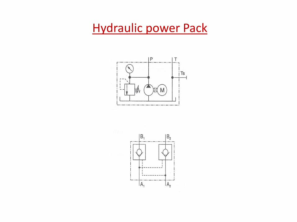
Hydraulic power Pack

Measuring devices

Signal flow in Hydraulic System

Hydraulic System

Hydraulic System

Technical data

Directional Control Valve

Flow Control valve

Pressure relief valve

Non return Valve

Double Acting Cylinder

Hydraulic Motor(gear motor)

Hydraulic Power Unit

17 June 2015 69


