EE 209 Fundamentals of Electrical and Electronics Engineering, Prof. Dr. O. SEVAİOĞLU, Page 1 METU Basic Principles of Electricity by Prof. Dr. Osman SEVAİOĞLU Electrical and Electronics Engineering Department Basic Principles of Electricity
Transcript
EE 209 Fundamentals of Electrical and Electronics Engineering, Prof. Dr. O. SEVAİOĞLU, Page 1
METU
Basic Principles of Electricity
by
Prof. Dr. Osman SEVAİOĞLU
Electrical and Electronics Engineering Department
Ba
sic
P
rin
cip
le
s o
f
Ele
ctric
ity
EE 209 Fundamentals of Electrical and Electronics Engineering, Prof. Dr. O. SEVAİOĞLU, Page 2
METU
Basic Principles of Electricity
EE 209
Fundamentals of Electrical and Electronics
Engineering (3-0)3
Course Syllabus
(Offered to non-EE students only)
Prerequisite: PHYS 106 or consent of the department.
• Basic Principles of Electricity,
• Circuit Analysis,
• AC Circuits,
• AC Power,
• Phasors,
• Three Phase Systems,
• Transformers,
• Magnetic Circuits,
• Electrical Safety
EE 209 Fundamentals of Electrical and Electronics Engineering, Prof. Dr. O. SEVAİOĞLU, Page 3
METU
Basic Principles of Electricity
Book for the Course
EE 209 Fundamentals of Electrical and Electronics Engineering, Prof. Dr. O. SEVAİOĞLU, Page 4
METU
Basic Principles of Electricity
Book for the Course
Principles and Applications of
Electrical Engineering, 4/e
Giorgio Rizzoni
The Ohio State University
Mc. Graw Hill Book Company,
ISBN: 0072463473
Copyright year: 2003
999 Pages
Available in Reserve Division of the
Middle East Technical University
Central Library
EE 209 Fundamentals of Electrical and Electronics Engineering, Prof. Dr. O. SEVAİOĞLU, Page 5
METU
Basic Principles of Electricity
Course Syllabus
Chapters to be Covered
• Basic Principles of Electricity,
• Circuit Analysis,
• AC Circuits,
• AC Power,
• Phasors,
• Three Phase Systems,
• Transformers,
• Magnetic Circuits,
• Electrical Safety
EE 209 Fundamentals of Electrical and Electronics Engineering, Prof. Dr. O. SEVAİOĞLU, Page 6
The Course Instructor keeps the right of not answering some or all
of the questions, suggestions, complaints, demands, requests
forwarded in this mail group, in case that it is not necessary, or not
relevant, or not possible
EE 209 Fundamentals of Electrical and Electronics Engineering, Prof. Dr. O. SEVAİOĞLU, Page 15
METU
Basic Principles of Electricity
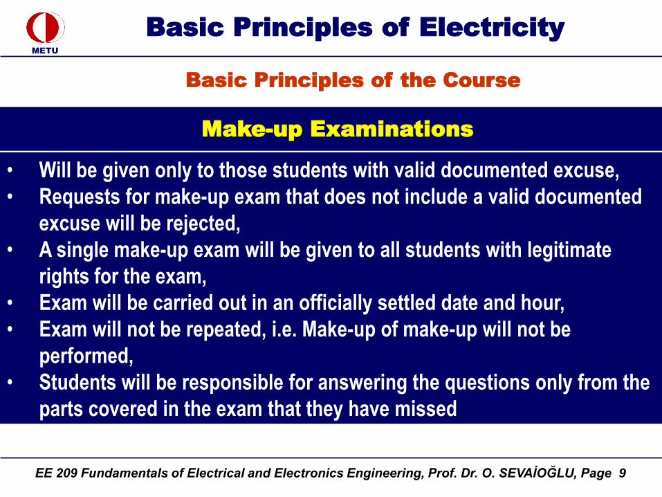
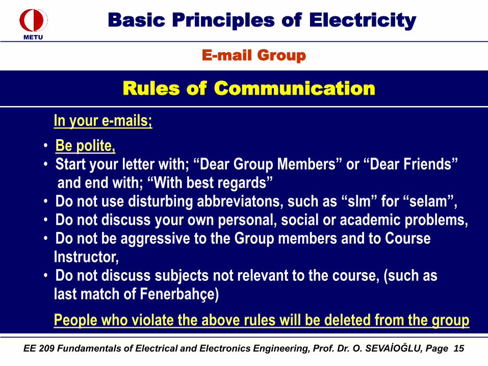
Rules of Communication
E-mail Group
In your e-mails;
• Be polite,• Start your letter with; “Dear Group Members” or “Dear Friends”
and end with; “With best regards”• Do not use disturbing abbreviatons, such as “slm” for “selam”,• Do not discuss your own personal, social or academic problems,• Do not be aggressive to the Group members and to Course
Instructor,• Do not discuss subjects not relevant to the course, (such as
last match of Fenerbahçe)
People who violate the above rules will be deleted from the group
EE 209 Fundamentals of Electrical and Electronics Engineering, Prof. Dr. O. SEVAİOĞLU, Page 16
METU
Basic Principles of Electricity
Course Instructor is the Main Moderator of the e-mail Group.
Assistant Moderator
An assistant moderator who is familiar with the management of
yahoogroups activities, will be elected and appointed for managing
the group from valunteer candidates in the class during the first hour.
Moderators have identical authorities in group management in all
respects
Group Moderators
E-mail Group
EE 209 Fundamentals of Electrical and Electronics Engineering, Prof. Dr. O. SEVAİOĞLU, Page 17
METU
Basic Principles of Electricity
Complaints and expressions concerning your;• personal, • Social, • Academic problems will never be listened, nor be appreciated nor be interested.
Complaints and Expressions
Problems
• Your personal, social and academic problems will never be aninfluencing factor in grading,
• Your personal, social and academic problems will not be taken into accountat all
This course is NOT a proper platform for expressing your own problems, negative or positive human feelings, such as, crying, complaining, hating, admiring, or any other physiologic, psychological expressions
EE 209 Fundamentals of Electrical and Electronics Engineering, Prof. Dr. O. SEVAİOĞLU, Page 18
METU
Basic Principles of Electricity
Unfortunately, there will not be any chance for office hour
• Please do not refer my office for any reason,
• and do not blame for that.
Office Hours
E-mail Group
EE 209 Fundamentals of Electrical and Electronics Engineering, Prof. Dr. O. SEVAİOĞLU, Page 19
METU
Basic Principles of Electricity
My GSM No: 0 532 384 78 65
Telephone calls for concerning your personal, social and academic
problems will neither be listened, nor be appreciated nor be interested
Telephone Calls
E-mail Group
EE 209 Fundamentals of Electrical and Electronics Engineering, Prof. Dr. O. SEVAİOĞLU, Page 20
METU
Basic Principles of Electricity
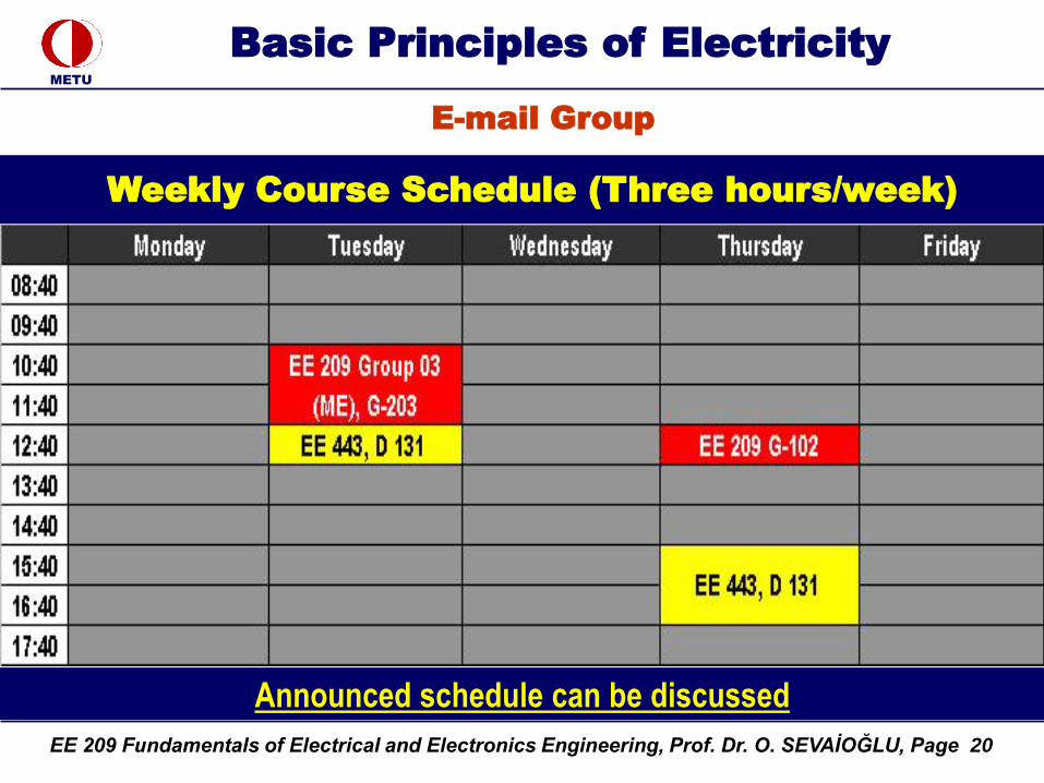
Weekly Course Schedule (Three hours/week)
E-mail Group
Announced schedule can be discussed
EE 209 Fundamentals of Electrical and Electronics Engineering, Prof. Dr. O. SEVAİOĞLU, Page 21
METU
Basic Principles of Electricity
Electron is assumed to be negatively charged
Proton is assumed to be positive charged
Atom
Structure of atom
Neutron
Proton
Electron
Helium Atom
EE 209 Fundamentals of Electrical and Electronics Engineering, Prof. Dr. O. SEVAİOĞLU, Page 22
METU
Basic Principles of Electricity
Unit of Electrical Charge Coulomb
Electrical Charge
Definition
6.3 x 10¹⁸ electrons = 1 Coulomb
or
Electrical charge / electron = 1/ (6.3 x 10¹⁸)
Coulomb
= 1.602 x 10⁻¹⁹ Coulomb
EE 209 Fundamentals of Electrical and Electronics Engineering, Prof. Dr. O. SEVAİOĞLU, Page 23
METU
Basic Principles of Electricity
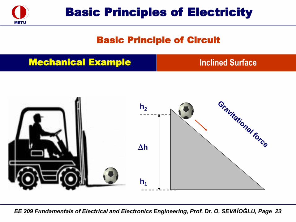
h
h1
Basic Principle of Circuit
h2
Mechanical Example Inclined Surface
EE 209 Fundamentals of Electrical and Electronics Engineering, Prof. Dr. O. SEVAİOĞLU, Page 24
METU
Basic Principles of Electricity
Water Circuit
Pump
Water Current (I)
Water Current = Volume (m3) / sec
EE 209 Fundamentals of Electrical and Electronics Engineering, Prof. Dr. O. SEVAİOĞLU, Page 25
METU
Basic Principles of Electricity
Pump
P1
P2
Gravitatio
nal fo
rce
P = P2 - P1
Water Circuit
Water Current (I)
EE 209 Fundamentals of Electrical and Electronics Engineering, Prof. Dr. O. SEVAİOĞLU, Page 26
METU
Basic Principles of Electricity
Electrical Circuit
Electrical Current = No. of electrons / sec = 1 Coulomb / sec
6.3 x 10¹⁸ electrons / sec = 1 Amper
Ele
ctr
om
oti
ve f
orc
e
Consumer(Load)
Electrical Current (I)
EE 209 Fundamentals of Electrical and Electronics Engineering, Prof. Dr. O. SEVAİOĞLU, Page 27
METU
Basic Principles of Electricity
Electrical Circuit
Vo
ltag
e (V
)
Current (I)
+
Ele
ctr
om
oti
ve f
orc
e
Consumer(Load)
Electrical Current (I)
EE 209 Fundamentals of Electrical and Electronics Engineering, Prof. Dr. O. SEVAİOĞLU, Page 28
METU
Basic Principles of Electricity
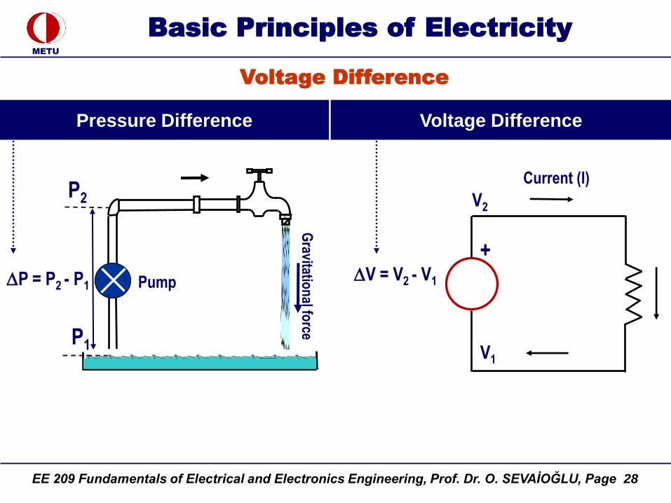
Pump
P1
P2
Gravitatio
nal fo
rce
P = P2 - P1
Voltage Difference
Current (I)
+V = V2 - V1
V2
V1
Voltage Difference Pressure Difference
EE 209 Fundamentals of Electrical and Electronics Engineering, Prof. Dr. O. SEVAİOĞLU, Page 29
METU
Basic Principles of Electricity
Ground Node is the point
(junction) at which the voltage is
assumed to be zero
Definition
Ground Node (Earth Point)
All other voltages takes their references with respect to this ground node
Ground Node
V1 = 0
Representation
Current (I)
+V = V2 - V1
= V2
V2
V1
EE 209 Fundamentals of Electrical and Electronics Engineering, Prof. Dr. O. SEVAİOĞLU, Page 30
METU
Basic Principles of Electricity
Ground Node is the point (junction) at which the
voltage is assumed to be zero
Definition
Ground Node (Earth Point)
All other voltages takes their references with respect to this ground node
Measured Node
(Red Terminal )
Ground Node
(Black Terminal )
EE 209 Fundamentals of Electrical and Electronics Engineering, Prof. Dr. O. SEVAİOĞLU, Page 31
METU
Basic Principles of Electricity
Voltage difference
(V)
Current
(I)
Current = no. of electrons transferred / time duration
I = Q / t
1 Amp = 1 Coulomb / 1 Seconds
Current
(I)
Electrical Current
Consumer
(Load)
Charge = Current x Time duration
Q = I x t
+
EE 209 Fundamentals of Electrical and Electronics Engineering, Prof. Dr. O. SEVAİOĞLU, Page 32
METU
Basic Principles of Electricity
Traffic Current
Cars Flowing in a Highway
Traffic Current = Cars / minute
EE 209 Fundamentals of Electrical and Electronics Engineering, Prof. Dr. O. SEVAİOĞLU, Page 33
METU
Basic Principles of Electricity
Water Current
Birecik Dam (672 MW)
Water Current = Volume (m3) / secWater Current = 500 m3 / sec
EE 209 Fundamentals of Electrical and Electronics Engineering, Prof. Dr. O. SEVAİOĞLU, Page 34
METU
Basic Principles of Electricity
Example: Electrical Current
1 m
ete
r
2 mm diameter
EE 209 Fundamentals of Electrical and Electronics Engineering, Prof. Dr. O. SEVAİOĞLU, Page 35
METU
Basic Principles of Electricity
Example: Electrical Current
1 m
ete
r
2 mm diameter
EE 209 Fundamentals of Electrical and Electronics Engineering, Prof. Dr. O. SEVAİOĞLU, Page 36
METU
Basic Principles of Electricity
Electrical Current
1 m
ete
r
2 mm diameter
EE 209 Fundamentals of Electrical and Electronics Engineering, Prof. Dr. O. SEVAİOĞLU, Page 37
EE 209 Fundamentals of Electrical and Electronics Engineering, Prof. Dr. O. SEVAİOĞLU, Page 39
METU
Basic Principles of Electricity
Simple AC Circuit
Customer
Current
(I)
Generator
EE 209 Fundamentals of Electrical and Electronics Engineering, Prof. Dr. O. SEVAİOĞLU, Page 40
METU
Basic Principles of Electricity
Kirchoff’s Current Law (KCL)
Cars entering: 370
Cars leaving:
120
65
55
130
+
-----------
370
Basic Principle
Cars entering = Cars leaving
Balance
EE 209 Fundamentals of Electrical and Electronics Engineering, Prof. Dr. O. SEVAİOĞLU, Page 41
METU
Basic Principles of Electricity
Charges entering
Q1
Q2
Qn-1
+------------
Qin
Kirchoff’s Current Law (KCL)
Charges leaving
Qout = Qn
Balance
Qin = Qout or
Qin – Qout = 0 or
Q = 0
EE 209 Fundamentals of Electrical and Electronics Engineering, Prof. Dr. O. SEVAİOĞLU, Page 42
METU
Basic Principles of Electricity
Qn Coulombs/sec
or
Q = 0
or
Q / t = 0
ori = n
Ii = 0i =1
Kirchoff’s First Law
or
Kirchoffs Current Law
Kirchoff’s Current Law (KCL)
EE 209 Fundamentals of Electrical and Electronics Engineering, Prof. Dr. O. SEVAİOĞLU, Page 43
METU
Basic Principles of Electricity
Mechanical Force
F = m x a
Wagon
Mass = 1000 kg
Force = 1000 Newton
Accelaration = 1 m/sec2
Definition
Force needed to accelarate 1 kg of mass to 1 meter / sec2
is defined as 1 Newton
1 Newton = 1 kg x 1 meter / sec2
1000 Newton = 1000 kg x 1 meter / sec2
EE 209 Fundamentals of Electrical and Electronics Engineering, Prof. Dr. O. SEVAİOĞLU, Page 44
METU
Basic Principles of Electricity
Mechanical Energy
1 Joule = 1 Newton x 1 Meter
Wagon Wagon
1 Meter 1 Newton
Definition
1 Joule is the energy needed to move a
mass 1 meter by using 1 Newton force
EE 209 Fundamentals of Electrical and Electronics Engineering, Prof. Dr. O. SEVAİOĞLU, Page 45
METU
Basic Principles of Electricity
Power
Power is the work done within a certain unit of time, i.e. one second or one hour
Power = Energy / Duration
= 1 Joule / sec
Definition
Wagon Wagon
1 Meter 1 Newton
Energy = 1 Joule, Power = 1 Joule / sec.
1 sec
Wagon Wagon
1 Meter 0.5 Newton
Energy = 1 Joule, Power = 1 Joule / 2 sec.
2 seconds
Please note that force (and hence power) of the weak horse shown below is half of the first, but the work done (energy spent) is the same, i.e.Energy = 2 seconds x 0.5 Newton x 1 meter
EE 209 Fundamentals of Electrical and Electronics Engineering, Prof. Dr. O. SEVAİOĞLU, Page 46
METU
Basic Principles of Electricity
Mechanical Energy vs Electrical Energy
Mechanical Work = Electrical Work
Voltage
(V)
Current (I)
1 Joule
Electrical Energy (Work) = 1 Joule
+
Wagon Wagon
1 Meter 1 Newton
Mechanical Energy (Work) = 1 Joule
Mechanical Energy = Electrical Energy
Equivalance The same amount of energy may
be spent out by using electricity
EE 209 Fundamentals of Electrical and Electronics Engineering, Prof. Dr. O. SEVAİOĞLU, Page 47
METU
Basic Principles of Electricity
Electrical Power = 1 Joule / sec.
Voltage
(V)
Current (I)
+
(1 sec)
Wagon Wagon
1 Meter 1 Newton
Mechanical Power = 1 Joule / sec.
1 sec
Electrical Power
Similar to mechanical power, electrical power is the work done within a certain unit of time, i.e. one second or one hourElecrical Power = Electrical Energy / Duration
= 1 Joule / sec
Definition
EE 209 Fundamentals of Electrical and Electronics Engineering, Prof. Dr. O. SEVAİOĞLU, Page 48
METU
Basic Principles of Electricity
Equivalence of Mechanical and Electrical Powers
Mechanical Power = Electrical Power
Wagon Wagon
1 Meter 1 Newton
Mechanical Power = 1 Joule / sec.
1 sec
Equivalance
Electrical Power = 1 Joule / sec.
Voltage
(V)
Current (I)
+
(1 sec)
EE 209 Fundamentals of Electrical and Electronics Engineering, Prof. Dr. O. SEVAİOĞLU, Page 49
METU
Basic Principles of Electricity
Electrical Power
1 Joule / second = 1 Watt
(1 Joule energy is spent within 1 second)
Wagon Wagon
1 Meter 1 Newton
1 Joule / sec = 1 Watt
1 sec
Definition 1 Joule = 1 Watt x second
1 Horse Power = 746 Watts= 0.746 kWatt
Electrical Power = 1 Joule / sec. = 1 Watt
Voltage
(V)
Current (I)
+
(1 sec)
EE 209 Fundamentals of Electrical and Electronics Engineering, Prof. Dr. O. SEVAİOĞLU, Page 50
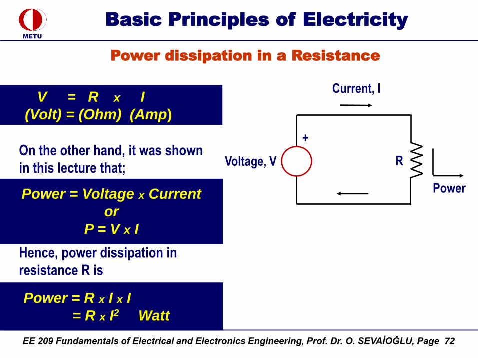
METU
Basic Principles of Electricity
Electrical Power
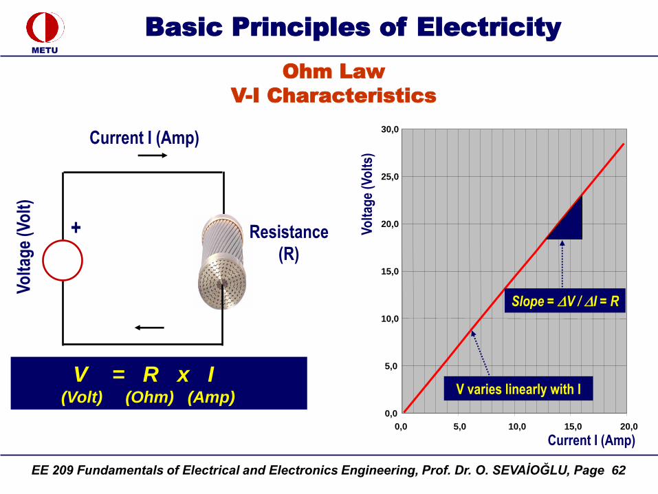
Power = Voltage x Current
DC Voltage
(Volt)
Current (Amp)
+
Power (Watt)
P = V x I
(Watt) = (Volt) x (Amp)
Definition
EE 209 Fundamentals of Electrical and Electronics Engineering, Prof. Dr. O. SEVAİOĞLU, Page 51
METU
Basic Principles of Electricity
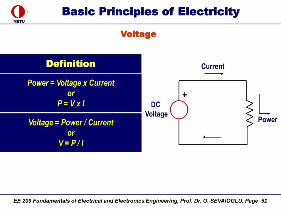
Voltage
Power = Voltage x Current
or
P = V x I DC
Voltage
Current
+
PowerVoltage = Power / Current
or
V = P / I
Definition
EE 209 Fundamentals of Electrical and Electronics Engineering, Prof. Dr. O. SEVAİOĞLU, Page 52
METU
Basic Principles of Electricity
Voltage
DC Voltage
(1 Volt)
Current (1 Amp)
+Power
(1 Watt)
Power = Voltage x Current
Voltage = Power / Current
or
V = P / I
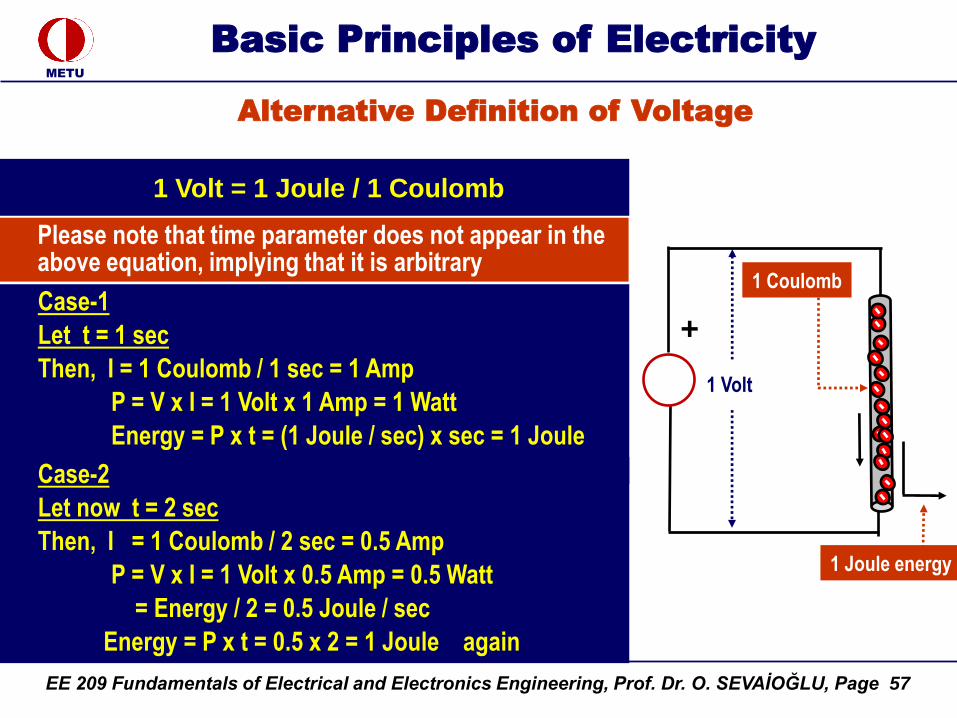
1 Volt = 1 Watt / 1 Amp
or
Definition
EE 209 Fundamentals of Electrical and Electronics Engineering, Prof. Dr. O. SEVAİOĞLU, Page 53
METU
Basic Principles of Electricity
Electrical Energy
Energy = Power x Time
(Watt-sec) (Watt) (second)DC Voltage
(V)
Current (I)
+
Energy = Power x Time
Definition
EE 209 Fundamentals of Electrical and Electronics Engineering, Prof. Dr. O. SEVAİOĞLU, Page 54
METU
Basic Principles of Electricity
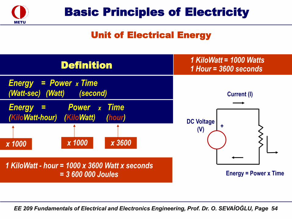
Unit of Electrical Energy
Energy = Power x Time(Watt-sec) (Watt) (second)
DC Voltage
(V)
Current (I)
+
Energy = Power x Time
Energy = Power x Time (KiloWatt-hour) (KiloWatt) (hour)
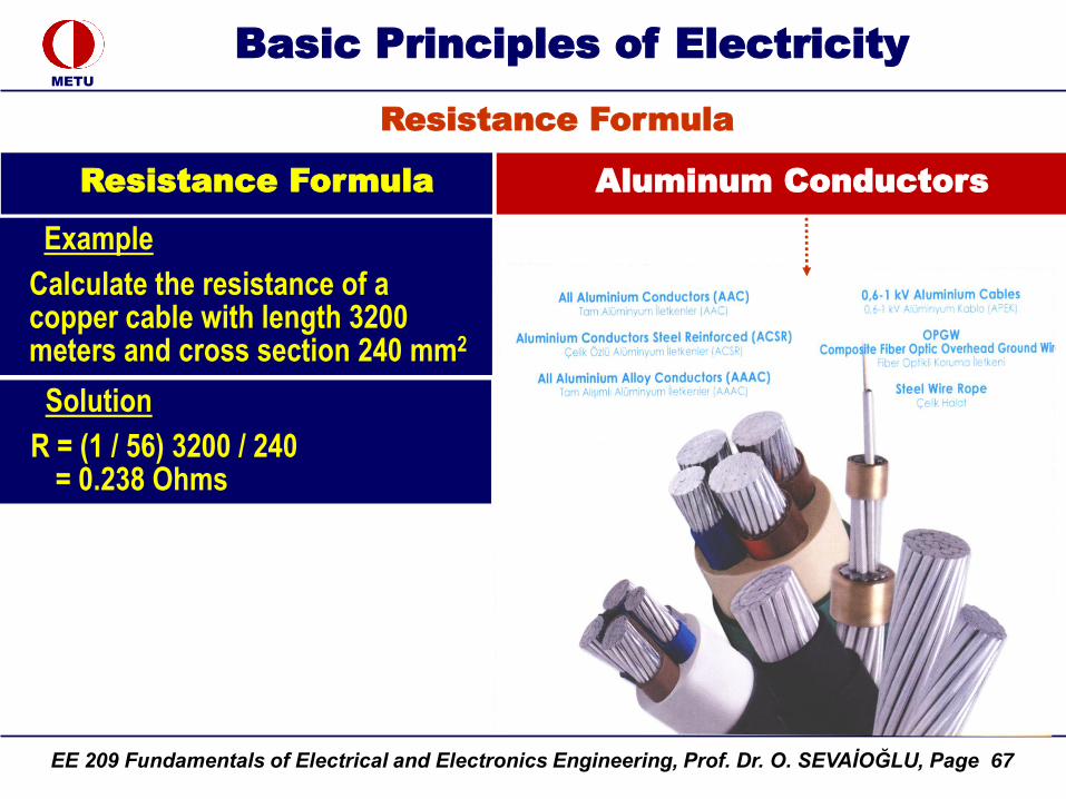
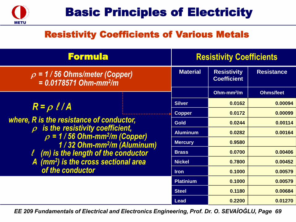
EE 209 Fundamentals of Electrical and Electronics Engineering, Prof. Dr. O. SEVAİOĞLU, Page 80
METU
Basic Principles of Electricity
Shunt Connected Resistances
Example
R1 = 1 Ohm
R2 = 2 Ohms
Rk = 4 Ohms
I1
I2
Ik
V = VT
ITotal
1
R equiv = -------------------------------------
1 / R1 + 1 / R2 + ...+ 1 / Rk
Find the equivalent resistance of the following connection
1
R equiv = ---------------------------------
1 / 1 + 1 / 2 + 1 / 4
= 1 / (7/4) = 4 / 7 = 0.5714 Ohm
+
EE 209 Fundamentals of Electrical and Electronics Engineering, Prof. Dr. O. SEVAİOĞLU, Page 81
METU
Basic Principles of Electricity
Shunt Connected Resistances
Example
1
1 / gequiv = -----------------------
g1 + g2 + ...+ gk
Find the equivalent admittance of the following connection
gequiv = g1 + g2 + g3
= 1 / 1 + 1 / 2 + 1 / 4
= 7 / 4
= 1.75 Siemens
g1 = 1/1 Siemens
g2 = 1/2 Siemens
gk = 1/4 Siemens
I1
I2
Ik
V = VT
ITotal
+
1
R equiv = -------------------------------------
1 / R1 + 1 / R2 + ...+ 1 / Rk
or
EE 209 Fundamentals of Electrical and Electronics Engineering, Prof. Dr. O. SEVAİOĞLU, Page 82
METU
Basic Principles of Electricity
V = V1 + V2(Volt) (Volt) (Volt)
Voltages on series connected elements are added
V = V1 + ... + Vn-1(Volt) (Volt) (Volt)
or
generalizing
Current I (Amp)
V1 (Volt)+
V2 (Volt)
+
+Vs (Volt)
Current I (Amp)
+
+
V1 (Volt)
V (Volt)
Vn-1 (Volt)
...
Voltages on Series Connected Elements
+
EE 209 Fundamentals of Electrical and Electronics Engineering, Prof. Dr. O. SEVAİOĞLU, Page 83
METU
Basic Principles of Electricity
V = V1 + ... + Vn-1
(Volt) (Volt) (Volt)
i = n-1
V = Vii =1
i = n-1
Vn - Vi = 0i = 1
i = n
Vi = 0i = 1
Voltages on series connected elements are added
Voltages on Series Connected Elements
+
+
V1(Volt)
V2 (Volt)
+
Current I (Amp)
Vs (Volt)
EE 209 Fundamentals of Electrical and Electronics Engineering, Prof. Dr. O. SEVAİOĞLU, Page 84
METU
Basic Principles of Electricity
Statement
i = n
Vi = 0i = 1
Current I (Amp)
+
+
V1(Volt)
V2 (Volt)
+
Kirchoff’s Voltage Law (KVL)
The above result may be expressed as;
Sum of voltages in a closed loop is zero
or
Kirchoff’s Second Law or
Kirchoff’s Voltage Law
Vs (Volt)
EE 209 Fundamentals of Electrical and Electronics Engineering, Prof. Dr. O. SEVAİOĞLU, Page 85
METU
Basic Principles of Electricity
Example
i = n
Vi = 0i = 1
Vs = 220 Volts
Vs – V1 – V2 = 0
220 – 100 – 120 = 0
Kirchoff’s Voltage Law (KVL)
Current I (Amp)
+
+
V1 = -100 (Volt)
V2 = -120 (Volt)
+
V = 220 V
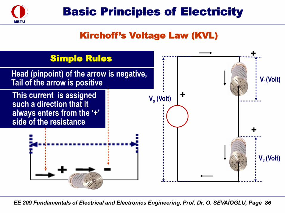
EE 209 Fundamentals of Electrical and Electronics Engineering, Prof. Dr. O. SEVAİOĞLU, Page 86
METU
Basic Principles of Electricity
Kirchoff’s Voltage Law (KVL)
Head (pinpoint) of the arrow is negative,Tail of the arrow is positive
Simple Rules
+
+
V1(Volt)
V2 (Volt)
+
This current is assigned such a direction that it always enters from the „+‟ side of the resistance
Vs (Volt)
EE 209 Fundamentals of Electrical and Electronics Engineering, Prof. Dr. O. SEVAİOĞLU, Page 87
METU
Basic Principles of Electricity
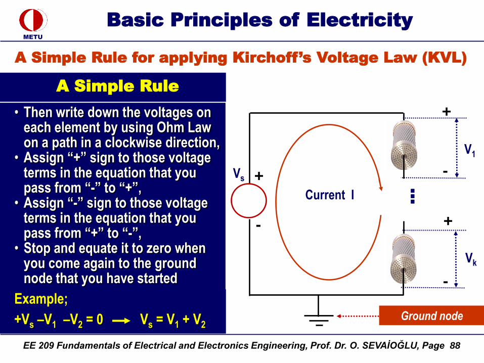
A Simple Rule for applying Kirchoff’s Voltage Law (KVL)
A Simple Rule
• Choose a ground node,• Assume that current I flows
clockwise,• Starting from the ground node,
assign “+” and “-” signs to those passive elements (i.e. those elements other than source) in such a direction that the current enters to “+” side and the leaves from the “-” side,
• Assign “+” sign to the that side of the source from which current is leaving
Vs
Current I
+
+
...
+
-
-
-
V1
Vk
Ground node
EE 209 Fundamentals of Electrical and Electronics Engineering, Prof. Dr. O. SEVAİOĞLU, Page 88
METU
Basic Principles of Electricity
A Simple Rule
• Then write down the voltages on each element by using Ohm Law on a path in a clockwise direction,
• Assign “+” sign to those voltage terms in the equation that you pass from “-” to “+”,
• Assign “-” sign to those voltage terms in the equation that you pass from “+” to “-”,
• Stop and equate it to zero when you come again to the ground node that you have started
Example;
+Vs –V1 –V2 = 0 Vs = V1 + V2
A Simple Rule for applying Kirchoff’s Voltage Law (KVL)
Vs
Current I
+
+
...
+
-
-
-
V1
Vk
Ground node
EE 209 Fundamentals of Electrical and Electronics Engineering, Prof. Dr. O. SEVAİOĞLU, Page 89
METU
Basic Principles of Electricity
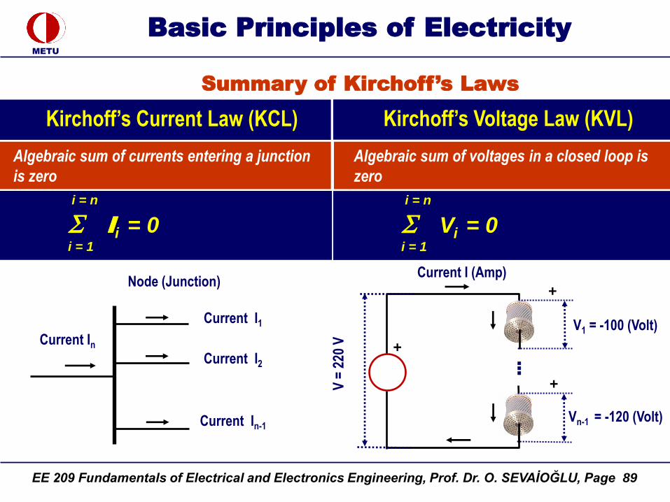
Summary of Kirchoff’s Laws
Kirchoff‟s Current Law (KCL)
i = n
Ii = 0i = 1
i = n
Vi = 0i = 1
Kirchoff‟s Voltage Law (KVL)
V =
220
V
Current I (Amp)
+
+
V1 = -100 (Volt)
Vn-1 = -120 (Volt)
...
+
Current In
Current I1
Current I2
Current In-1
Node (Junction)
Algebraic sum of currents entering a junction
is zero
Algebraic sum of voltages in a closed loop is
zero
EE 209 Fundamentals of Electrical and Electronics Engineering, Prof. Dr. O. SEVAİOĞLU, Page 90
METU
Basic Principles of Electricity
Voltage Division Principle
V1 = R1 x I
V2 = R2 x I
...
Vk = Rk x I
-----------------------------
Vs = V1 + V2 + ... Vk
= ( R1 + ... + Rk ) x I
Vk / Vs = Rk / ( R1 + ... + Rk )
Rk
Voltage Division Ratio = ------------------
R1 + ... + Rk
Input Voltage
Current I
Output Voltage
= Vs Rk / (R1+..Rk)
+
+
V1
Vk
+
V2
R1
Rk
R2
...
Vs
+
EE 209 Fundamentals of Electrical and Electronics Engineering, Prof. Dr. O. SEVAİOĞLU, Page 91
METU
Basic Principles of Electricity
Potentiometer (Voltage Divider)
Rk
Division Ratio = ---------------R1 + ... + Rk
Principle
Input voltage is divided and a certain fraction is given to the output
B CA
Current I
+
+
V1
Vk
+
V2
R1
Rk
R2
...
Vs
Rk
Vk = --------------- Vs
R1 + ... + Rk
EE 209 Fundamentals of Electrical and Electronics Engineering, Prof. Dr. O. SEVAİOĞLU, Page 92
METU
Basic Principles of Electricity
Potentiometer (Voltage Divider)
Rk
Division Ratio = ------------------
R1 + ... + Rk
Circuit Arrangement
Rotary Potentiometer
Rotary Potentiometer
EE 209 Fundamentals of Electrical and Electronics Engineering, Prof. Dr. O. SEVAİOĞLU, Page 93
METU
Basic Principles of Electricity
Current Division Principle
VT x g1 = I1VT x g2 = I2...
VT x gk = Ik
-----------------------------------
VT (g1 + ... gk ) = I1 + ... Ik
or
VT (g1 + ... gk ) = Is
Ik / Is = gk / ( g1 + ... + gk )
V = VT
g1
g2
gk
I1= VT x g1
I2= VT x g2
Ik= VT x gk = Isgk / (g1+...gk)
Source Current IsIs
+
gk
Division Ratio = ---------------g1 + ... + gk
gk
Ik = --------------- Isg1 + ... + gk
+
EE 209 Fundamentals of Electrical and Electronics Engineering, Prof. Dr. O. SEVAİOĞLU, Page 94
METU
Basic Principles of Electricity
Voltage Sources
Definition
Voltage source is an element which
creates a voltage difference at its
terminals
V = 24 Volts
V = 24 V
+
A simple Rule:Current is assigned such a direction that it always leaves the „+‟ side of the voltage or current source.
+
DC Voltage Source Voltage Source
V = 24 V
+ +
+
EE 209 Fundamentals of Electrical and Electronics Engineering, Prof. Dr. O. SEVAİOĞLU, Page 95
METU
Basic Principles of Electricity
Ideal Voltage Source
Definition
An ideal voltage source is the one that the terminal voltage does not change with the current drawn
V = 24 Volts
+
Vs = 24 V
Load Current I
+
Battery
VT = Vs
An ideal voltage source has zero internal resistance
0,0
5,0
10,0
15,0
20,0
25,0
30,0
0,0 5,0 10,0 15,0 20,0
Load Current I (Amp)
Term
inal
Vo
ltag
e (V
olt
s)
VT = constant
25,0
Internal resistance
V = R x I = 0
+
EE 209 Fundamentals of Electrical and Electronics Engineering, Prof. Dr. O. SEVAİOĞLU, Page 96
METU
Basic Principles of Electricity
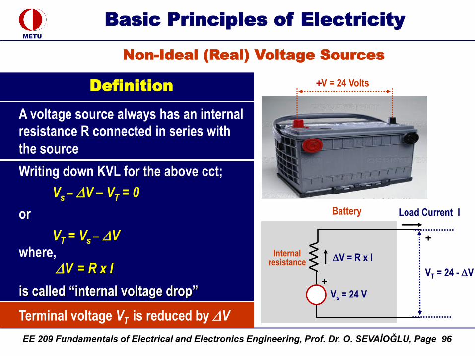
Non-Ideal (Real) Voltage Sources
Definition
A voltage source always has an internal
resistance R connected in series with
the source
V = 24 Volts
VT = 24 - V+
Vs = 24 V
V = R x I
Load Current I
+
Battery
Internal resistance
Writing down KVL for the above cct;
Vs – V – VT = 0
or
VT = Vs – Vwhere,
V = R x I
is called “internal voltage drop”
Terminal voltage VT is reduced by V
+
EE 209 Fundamentals of Electrical and Electronics Engineering, Prof. Dr. O. SEVAİOĞLU, Page 97
METU
Basic Principles of Electricity
Definition
VT = 24 - V
+
Vs = 24 V
V = R x I
Load Current I
+
Battery
Internal resistance
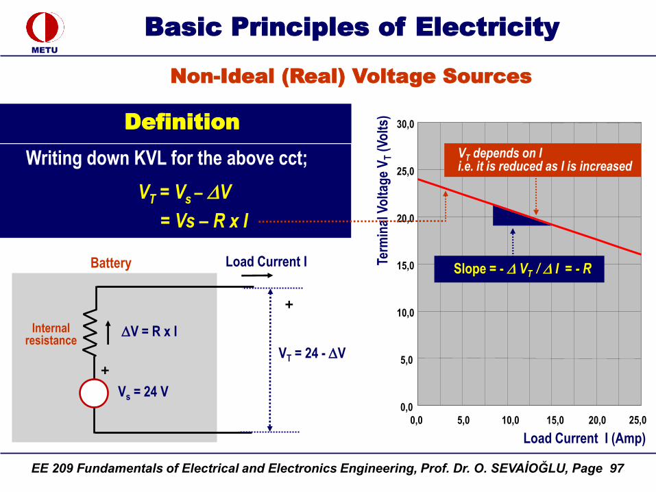
Writing down KVL for the above cct;
VT = Vs – V
= Vs – R x I
0,0
5,0
10,0
15,0
20,0
25,0
30,0
0,0 5,0 10,0 15,0 20,0
Load Current I (Amp)
Term
inal
Vo
ltag
e V
T(V
olt
s)
Slope = - VT / I = - R
25,0
Non-Ideal (Real) Voltage Sources
VT depends on Ii.e. it is reduced as I is increased
EE 209 Fundamentals of Electrical and Electronics Engineering, Prof. Dr. O. SEVAİOĞLU, Page 98
METU
Basic Principles of Electricity
Ideal Current Source
Ideal Current Source
An ideal current source is an element
providing a constant current from its
terminals
Terminal Current IT
Source Current Is
Source Current Is
IT = Is Ideal Current Source
Definition
EE 209 Fundamentals of Electrical and Electronics Engineering, Prof. Dr. O. SEVAİOĞLU, Page 99
METU
Basic Principles of Electricity
Non-Ideal (Real) Current Source
A non ideal current source is an element with a current depending on terminal voltage
Ideal Current Source Is
g =1 / R VT
I
Is
Terminal Current IT
IT = Is – I
IT = Is – g x VT
Current Source Is
Non-Ideal Current Source
Definition
+
EE 209 Fundamentals of Electrical and Electronics Engineering, Prof. Dr. O. SEVAİOĞLU, Page 100
METU
Basic Principles of Electricity
Non-Ideal (Real) Current Source
A non ideal current source is an element with a current depending on terminal voltage
Terminal Current IT
IT = Is – I
IT = Is – g x VT
0,0
5,0
10,0
15,0
20,0
25,0
30,0
0,0 5,0 10,0 15,0 20,0
Terminal Voltage (Volts)
Term
inal
Cu
rren
t I s
(Am
p)
IT depends on Vi.e. it is reduced as V is increased
Non-Ideal Current Source
Slope = - IT / VT = - g
25,0
Definition:
Non-Ideal Current Source
Ideal Current Source Is
g =1 / R VT
I
Is
+
EE 209 Fundamentals of Electrical and Electronics Engineering, Prof. Dr. O. SEVAİOĞLU, Page 101
METU
Basic Principles of Electricity
Controlled (Dependent) Sources
Definition: Controlled Sources
A controlled source is an element with a current or voltage depending on any other voltage or current in the circuit
Controlled Source: Current Is = A Vx
A = Amplification coefficient
Voltage Controlled Current Source
Is = A Vx
VxIs
Voltage Controlled Current Source
Terminal Current: ITIs
+
EE 209 Fundamentals of Electrical and Electronics Engineering, Prof. Dr. O. SEVAİOĞLU, Page 102
METU
Basic Principles of Electricity
Controlled (Dependent) Sources
Definition: Controlled Sources
A controlled source is an element with a current or voltage depending on any other voltage or current in the circuit
Controlled Source: Current Is = A Ix
Current Controlled Current Source
Is = A Ix
IxIs
Current Controlled Current Source
Terminal Current: ITIs
It - Is
EE 209 Fundamentals of Electrical and Electronics Engineering, Prof. Dr. O. SEVAİOĞLU, Page 103
METU
Basic Principles of Electricity
Controlled (Dependent) Sources
Definition: Controlled Sources
A controlled source is an element with a current or voltage depending on any other voltage or current in the circuit
Voltage Controlled
Voltage Source
Vs = A Vx
Vs
Voltage Controlled Voltage Source
Vx
+Controlled Source: Voltage Vs = A Vx+
EE 209 Fundamentals of Electrical and Electronics Engineering, Prof. Dr. O. SEVAİOĞLU, Page 104
METU
Basic Principles of Electricity
Controlled (Dependent) Sources
Definition: Controlled Sources
A controlled source is an element with a current or voltage depending on any other voltage or current in the circuit
Current Controlled Voltage Source
Current Controlled
Voltage Source
Vs = A Ix
Vs
+
Ix
Controlled Source: Voltage Vs = A Ix
Terminal Current: ITIs
It - Is
EE 209 Fundamentals of Electrical and Electronics Engineering, Prof. Dr. O. SEVAİOĞLU, Page 105
METU
Basic Principles of Electricity
Example
Question
Solve the circuit on the RHS for current Ix Current Controlled
Voltage Source
Vs = 10 Ix
Vs
+
Ix
10 V
+
2 Ohm
Write down KVL;
Vs – 10 – 2 Ix = 0
10 Ix – 10 – 2 Ix = 0
8 Ix = 10 → Ix = 10 / 8 = 1.25 Amp
Solution
Current Controlled Voltage Source
Terminal Current: ITIs
EE 209 Fundamentals of Electrical and Electronics Engineering, Prof. Dr. O. SEVAİOĞLU, Page 106
EE 209 Fundamentals of Electrical and Electronics Engineering, Prof. Dr. O. SEVAİOĞLU, Page 107
METU
Basic Principles of Electricity
Measuring Devices - Ammeter
+
Ammeter
An ammeter is always series connected in the circuit measured
Ampere - Volt - Ohm (AVO)Meter
Iload
RL
EE 209 Fundamentals of Electrical and Electronics Engineering, Prof. Dr. O. SEVAİOĞLU, Page 108
METU
Basic Principles of Electricity
Measuring Devices - Ammeter
An ammeter is always series connected in the circuit measured
+
Ammeter
RL
Ramp
Internal Resistance of Ammeter
Iload
EE 209 Fundamentals of Electrical and Electronics Engineering, Prof. Dr. O. SEVAİOĞLU, Page 109
METU
Basic Principles of Electricity
Ideal Ammeter
No ammeter can ever be ideal, and hence all ammeters have some internal resistance
+
Ammeter
RLVs
IloadRamp 0
Definition
An ideal ammeter is the one with zero internal resistance (Short Circuit)
• An ideal ammeter behaves as a short circuit, i.e. Ramp 0.
• An ideal ammeter has zero resistance so that the measured current is not influenced
EE 209 Fundamentals of Electrical and Electronics Engineering, Prof. Dr. O. SEVAİOĞLU, Page 110
METU
Basic Principles of Electricity
Ideal Ammeter
Ramp 0
+
Ammeter
RL
I = Vs / ( R + Ramp )
Ramp 0
Hence,
I = Vs / ( R + Ramp ) Vs / R
An ammeter should not influence the current measured
Iload
EE 209 Fundamentals of Electrical and Electronics Engineering, Prof. Dr. O. SEVAİOĞLU, Page 111
METU
Basic Principles of Electricity
Non-Ideal (Real) Ammeter
No ammeter can ever be ideal, and henceall ammeters have some internal resistance
Definition
A real (non-ideal) ammeter has always an internal resistance in series
• A non ideal ammeter behaves as a series resistance with: Ramp ≠ 0
• Hence the the measured current is influenced (reduced)
Iload = Vs / ( R + Ramp )
I load = Vs / R
+
Ammeter
RL
Vs
IloadRamp
Non-ideal Ammeter
} Iload < I ideal
EE 209 Fundamentals of Electrical and Electronics Engineering, Prof. Dr. O. SEVAİOĞLU, Page 112
METU
Basic Principles of Electricity
Measuring Devices – Clamp Ammeter
Sometimes the electrical service carried out by the circuit may be so vital that it can not be interrupted by breaking the line for a series connection of the ammeter
Ammeter shown on the RHS is a particular design for such circuits to measure current flowing in the circuit as well as resistance without braeaking the circuit
The Need for Clamp Ammeter
EE 209 Fundamentals of Electrical and Electronics Engineering, Prof. Dr. O. SEVAİOĞLU, Page 113
METU
Basic Principles of Electricity
Measuring Devices - Voltmeter
A voltmeter has a high internal resistance so that it passes
only a small current
An ideal voltmeter has a very large resistance so that the the
circuit in which it has been placed is not disturbed
An ideal voltmeter is an open circuit
However, no voltmeter can ever be ideal, and therefore all
voltmeters draw some small current
Voltmeter is always parallel connected to the terminals measured
EE 209 Fundamentals of Electrical and Electronics Engineering, Prof. Dr. O. SEVAİOĞLU, Page 114
METU
Basic Principles of Electricity
Measuring Devices - Voltmeter
A voltmeter has a high internal
resistance so that it passes only a small
current
A voltmeter is always shunt (parallel) connected in the circuit that it measures
RL
Vo = Vs ------------
R1 + RL
Measured voltage;
Red lines are not part of the circuit
I Voltmeter
(negligible)
I Load
+
RL
RmR1
Vs
Voltmeter
Vo
I Source
Voltmeter is always parallel connected to the terminals measured
EE 209 Fundamentals of Electrical and Electronics Engineering, Prof. Dr. O. SEVAİOĞLU, Page 115
METU
Basic Principles of Electricity
Ideal Voltmeter
An ideal voltmeter has a very large
resistance, Rm . i.e. it behaves as an
open circuit, so that the the measured
circuit is not influenced
However, no voltmeter can ever be ideal,
and therefore all voltmeters draw some
current
A real voltmeter has a certain internal
resistance so that it passes a certain
current
I m(negligible)
I Load
+
RL
RmR1
Vs
Voltmeter
Vo
I SourceDefinition
An ideal voltmeter is the one with infinite internal resistance (Open circuit)
EE 209 Fundamentals of Electrical and Electronics Engineering, Prof. Dr. O. SEVAİOĞLU, Page 116
METU
Basic Principles of Electricity
Ideal Voltmeter
No voltmeter can ever be ideal, and
therefore all voltmeters draw some
current.
Vo = RL ( Isource – Im )
= RL I Source – RL Im
RL I Source
}Negligible
I m(negligible)
I Load
+
RL
RmR1
Vs
Voltmeter
Vo
I Source
Rm i.e. Rm >> RL
I m << I Load
ISource = ILoad + Im I Load
EE 209 Fundamentals of Electrical and Electronics Engineering, Prof. Dr. O. SEVAİOĞLU, Page 117
METU
Basic Principles of Electricity
Example
Calculate the internal admittance gm of a voltmeter, if it reads 11.81 Volts when connected to a 0.48 mA current source with an internal admittance of gs = 4 x 10⁻⁵ Siemens
Problem
Siemens = 1/
Vread = 11.81 V
IS=0.48 mA
Voltmeter
gs= 4 x 10⁻⁵ S
+
gm = 1/Rm
Non-ideal Voltmeter
I g I m
(negligible)
I g
Ideal Voltmeter Im 0
EE 209 Fundamentals of Electrical and Electronics Engineering, Prof. Dr. O. SEVAİOĞLU, Page 118
METU
Basic Principles of Electricity
Example
Rs = 1 / gs = 1 / (4 x10⁻⁵) Siemens
= 105 / 4 = 25 k
Is x Req = Vread = 11.81 Volts
Hence,
Req = Vread / Is = 11.81 / (0.48 x 10⁻³)
= 24607.17
Req = Rs // Rm
Hence,
Req =(Rs x Rm) / (Rs + Rm) = 24607.17
Rm = 155.39 M
Problem Ideal Voltmeter
Vread = 11.81 VIS=0.48 mA
Voltmeter
gs= 4 x 10⁻⁵ S
+
gm = 1/Rm
Non-ideal Voltmeter
I g I m
(negligible)
I g
Im 0
EE 209 Fundamentals of Electrical and Electronics Engineering, Prof. Dr. O. SEVAİOĞLU, Page 119
METU
Basic Principles of Electricity
Advanced Measuring Devices
Power Quality Analyzer
EE 209 Fundamentals of Electrical and Electronics Engineering, Prof. Dr. O. SEVAİOĞLU, Page 120
METU
Basic Principles of Electricity
Wheatstone Bridge
The Wheatstone Bridge is an electrical circuit
used to determine an unknown resistance Rx
by adjusting the values of known resistances,
so that the current measured in the line
connecting the terminals C and D is zero
I = 0
x
A
B
C D
Rb R2Rx R1
EE 209 Fundamentals of Electrical and Electronics Engineering, Prof. Dr. O. SEVAİOĞLU, Page 121
METU
Basic Principles of Electricity
Wheatstone Bridge
Principle
Adjust the resistances R1, R2
and Rb such that the ammeter
connected between the
terminals C and D reads zero
current
V CD = 0
or
VC = VD
Hence, the voltage difference
between the terminals C and D is
zero
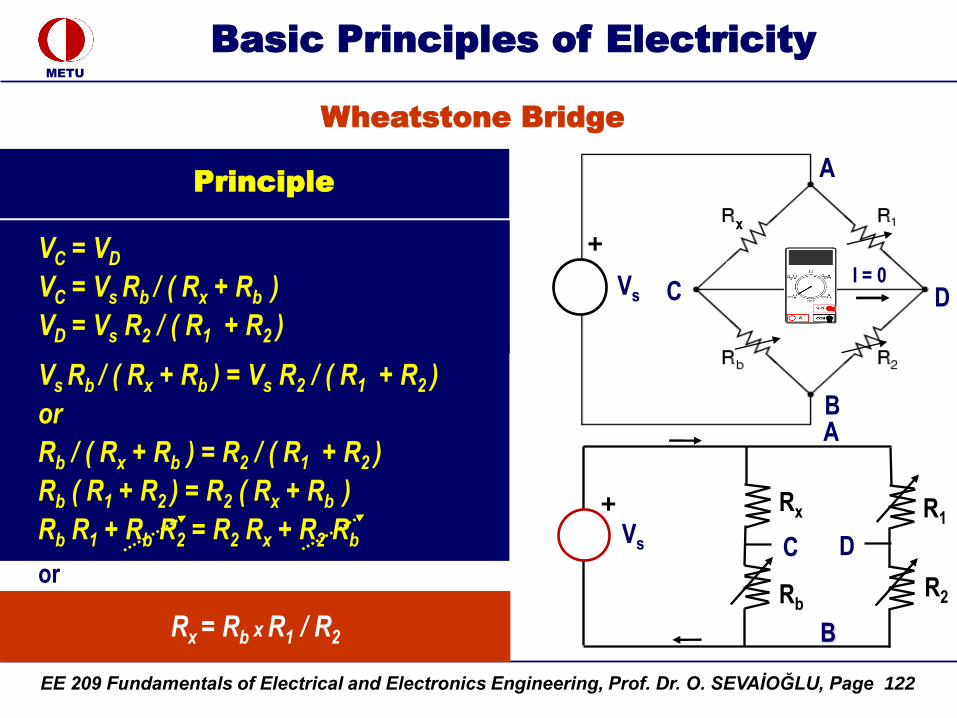
EE 209 Fundamentals of Electrical and Electronics Engineering, Prof. Dr. O. SEVAİOĞLU, Page 122
METU
Basic Principles of Electricity
Wheatstone Bridge
Principle
Rx = Rb x R1 / R2
+
B
C D
Rx R1
RbR2
Vs
or
VC = VD
VC = Vs Rb / ( Rx + Rb )
VD = Vs R2 / ( R1 + R2 )
Vs Rb / ( Rx + Rb ) = Vs R2 / ( R1 + R2 )
or
Rb / ( Rx + Rb ) = R2 / ( R1 + R2 )
Rb ( R1 + R2 ) = R2 ( Rx + Rb )
Rb R1 + Rb R2 = R2 Rx + R2 Rb
A
Vs
A
B
C D
+I = 0
x
A
EE 209 Fundamentals of Electrical and Electronics Engineering, Prof. Dr. O. SEVAİOĞLU, Page 123
METU
Basic Principles of Electricity
Wheatstone Bridge
Basic Rule
Rx x R2 = Rb x R1
Cross multiplication branch resistances must be equal at balance condition
Please note that voltage Vsis neither used, nor needed in the above equation, i.e. its value is arbitrary
Vs
A
B
C D
+
I = 0
x
EE 209 Fundamentals of Electrical and Electronics Engineering, Prof. Dr. O. SEVAİOĞLU, Page 124
METU
Basic Principles of Electricity
Wheatstone Bridge
Example
Calculate the value of unknown resistance Rx in the balanced Wheatstone Bridge shown on the RHS
Rx x R2 = Rb x R1
Cross multiplication of branch resistances must be equal at balance condition:
Rx = Rb x R1 / R2
= 100 x 100 / 20 = 500 Ohm
EE 209 Fundamentals of Electrical and Electronics Engineering, Prof. Dr. O. SEVAİOĞLU, Page 125
METU
Basic Principles of Electricity
Switch - Circuit Breaker
Switch or circuit breaker is a device used to open an electrical circuit manually or automatically by an electronic relay system
Switch or Circuit Breaker
Open
“Off”
Closed
“On”
I Load
+
R1
Vs
Switch
R1
EE 209 Fundamentals of Electrical and Electronics Engineering, Prof. Dr. O. SEVAİOĞLU, Page 126
METU
Basic Principles of Electricity
Meaning of “Open” and “Closed” (Highly Important)
Open Circuit or Switch Closed Circuit or Switch
Open Circuit
Breaker
+
R1
VsR1
I Load
Open (On), Closed (Off) Open (Off) Switch Closed (On) SwitchClosed Circuit
+
R1
Vs
R1
I Load = 0
“Closed Switch (On)” does NOT mean that there is no voltage
(current) in the circuit !
EE 209 Fundamentals of Electrical and Electronics Engineering, Prof. Dr. O. SEVAİOĞLU, Page 127
METU
Basic Principles of Electricity
Thermal-Magnetic Circuit Breaker
220 Volt, 63 Amp. Thermal-Magnetic (Molded-Case) Breaker
+
R1
Vs R1
I Load
Open (Off)
Switch
Closed
Circuit
+
R1
VsR1
I Load = 0
“Closed Switch (On)” does NOT mean that
there is no voltage (current) in the circuit !
Closed (On)
SwitchOpen Circuit
EE 209 Fundamentals of Electrical and Electronics Engineering, Prof. Dr. O. SEVAİOĞLU, Page 128
METU
Basic Principles of Electricity
Medium Voltage (36 kV) Vacuum Circuit Breaker
Open Circuit
+
R1
Vs
R1
I Load = 0Vacuum tube enclosing
breaker poles
Tripping buttons
Spring handle (taken off)
EE 209 Fundamentals of Electrical and Electronics Engineering, Prof. Dr. O. SEVAİOĞLU, Page 129