Basic Router Configuration This chapter provides procedures for configuring the basic parameters of your Cisco router, including global parameter settings, routing protocols, interfaces, and command-line access. It also describes the default configuration on startup. Individual router models may not support every feature described in this guide. Features that are not supported by a particular router are indicated whenever possible. Note This chapter includes configuration examples and verification steps, as available. For complete information on how to access global configuration mode, see the Entering Global Configuration Mode section. • Basic Router Configuration, page 1 Basic Router Configuration This chapter provides procedures for configuring the basic parameters of your Cisco router, including global parameter settings, routing protocols, interfaces, and command-line access. It also describes the default configuration on startup. Individual router models may not support every feature described in this guide. Features that are not supported by a particular router are indicated whenever possible. Note This chapter includes configuration examples and verification steps, as available. For complete information on how to access global configuration mode see Entering Global Configuration Mode, page A-5 . Interface Ports Table 1: Supported Interfaces and Associated Port Labels for Cisco 860, 880 and 890 Series Router , on page 2 lists the interfaces that are supported for Cisco 860, 880 and 890 series routers and their associated port labels on the equipment. Cisco 800 Series Integrated Services Routers Software Configuration Guide 1
Transcript
Basic Router Configuration
This chapter provides procedures for configuring the basic parameters of your Cisco router, including globalparameter settings, routing protocols, interfaces, and command-line access. It also describes the defaultconfiguration on startup.
Individual router models may not support every feature described in this guide. Features that are notsupported by a particular router are indicated whenever possible.
Note
This chapter includes configuration examples and verification steps, as available.
For complete information on how to access global configuration mode, see the Entering Global ConfigurationMode section.
• Basic Router Configuration, page 1
Basic Router ConfigurationThis chapter provides procedures for configuring the basic parameters of your Cisco router, including globalparameter settings, routing protocols, interfaces, and command-line access. It also describes the defaultconfiguration on startup.
Individual router models may not support every feature described in this guide. Features that are notsupported by a particular router are indicated whenever possible.
Note
This chapter includes configuration examples and verification steps, as available.
For complete information on how to access global configuration mode see Entering Global ConfigurationMode, page A-5 .
Interface PortsTable 1: Supported Interfaces and Associated Port Labels for Cisco 860, 880 and 890 Series Router , on page2 lists the interfaces that are supported for Cisco 860, 880 and 890 series routers and their associated portlabels on the equipment.
Cisco 800 Series Integrated Services Routers Software Configuration Guide 1
WAN GE1Gigabit Ethernet WANCisco 866VAE-K9, 867VAE-K9
VDSL/ADSL OVER ISDNVDSL/ADSLoISDN WANCisco 866VAE, 866VAE-K9
VDSL/ADSL OVER POTSVDSL/ADSLoPOTS WANCisco 867VAE, 867VAE-K9
Cisco 800 Series Integrated Services Routers Software Configuration Guide2
Basic Router ConfigurationInterface Ports
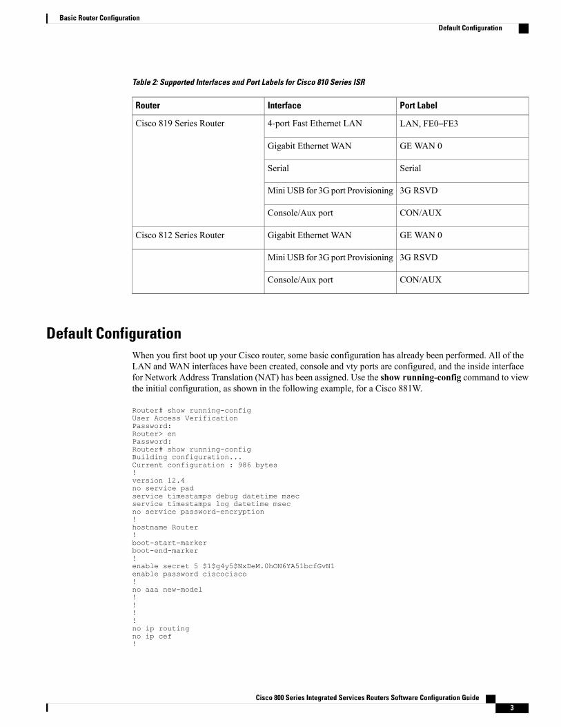
Table 2: Supported Interfaces and Port Labels for Cisco 810 Series ISR
Port LabelInterfaceRouter
LAN, FE0–FE34-port Fast Ethernet LANCisco 819 Series Router
GE WAN 0Gigabit Ethernet WAN
SerialSerial
3G RSVDMini USB for 3G port Provisioning
CON/AUXConsole/Aux port
GE WAN 0Gigabit Ethernet WANCisco 812 Series Router
3G RSVDMini USB for 3G port Provisioning
CON/AUXConsole/Aux port
Default ConfigurationWhen you first boot up your Cisco router, some basic configuration has already been performed. All of theLAN and WAN interfaces have been created, console and vty ports are configured, and the inside interfacefor Network Address Translation (NAT) has been assigned. Use the show running-config command to viewthe initial configuration, as shown in the following example, for a Cisco 881W.
Router# show running-configUser Access VerificationPassword:Router> enPassword:Router# show running-configBuilding configuration...Current configuration : 986 bytes!version 12.4no service padservice timestamps debug datetime msecservice timestamps log datetime msecno service password-encryption!hostname Router!boot-start-markerboot-end-marker!enable secret 5 $1$g4y5$NxDeM.0hON6YA51bcfGvN1enable password ciscocisco!no aaa new-model!!!!no ip routingno ip cef!
Cisco 800 Series Integrated Services Routers Software Configuration Guide 3
• If you are setting up a connection to a corporate network, you and the network administrator mustgenerate and share the following information for the WAN interfaces of the routers:
◦PPP authentication type: CHAP or PAP
◦PPP client name to access the router
◦PPP password to access the router
• If you are setting up IP routing:
◦Generate the addressing scheme for your IP network.
◦Determine the IP routing parameter information, including IP address and ATM permanent virtualcircuits (PVCs). These PVC parameters are typically virtual path identifier (VPI), virtual circuitidentifier (VCI), and traffic-shaping parameters.
◦Determine the number of PVCs that your service provider has given you, along with their VPIsand VCIs.
◦For each PVC, determine the type of AAL5 encapsulation supported. It can be one of the following:
AAL5SNAP—This can be either routed RFC 1483 or bridged RFC 1483. For routed RFC 1483, the serviceprovider must provide you with a static IP address. For bridged RFC 1483, you may use DHCP to obtain yourIP address, or you may obtain a static IP address from your service provider.
AAL5MUX PPP—With this type of encapsulation, you need to determine the PPP-related configurationitems.
• If you plan to connect over an ADSL or G.SHDSL line:
◦Order the appropriate line from your public telephone service provider.
For ADSL lines—Ensure that the ADSL signaling type is DMT (also known as ANSI T1.413) or DMT Issue2.
For G.SHDSL lines—Verify that the G.SHDSL line conforms to the ITU G.991.2 standard and supportsAnnex A (North America) or Annex B (Europe).
• If you are setting up 3G:
Cisco 800 Series Integrated Services Routers Software Configuration Guide 5
Basic Router ConfigurationInformation Needed for Configuration
Youmust have service availability on the Cisco 819 ISR from a carrier, and youmust have networkcoverage where your router will be physically placed. For a complete list of supported carriers,see the data sheet at Cisco 3G Wireless Connectivity Solutions.
◦
◦You must subscribe to a service plan with a wireless service provider and obtain a SIM card.
◦You must install the SIM card before configuring the 3G Cisco 819 ISR. For instructions on howto install the SIM card, see Cisco 800 Series see Configuring Cisco EHWIC and 880G for 3.7G(HSPA+)/3.5G (HSPA)
◦You must install the required antennas before you configure the 3G for Cisco 819 ISR. See Table3: Instructions for Installing Antenna, on page 6 for instructions on how to install the antennas:
Table 3: Instructions for Installing Antenna
Instructions for Installig AntennaAntenna
See Cisco Multiband Swivel-Mount Dipole Antenna(3G-ANTM1919D).
3G-ANTM1919D
See CiscoMultiband Omnidirectional CeilingMountAntenna (3G-ANTM1916-CM)
3G-ANTM1916-CM
See Cisco Single-Port Antenna Stand for MultibandTNC Male-Terminated Portable Antenna (Cisco3G-AE015-R).
3G-AE015-R (Antenna Extension)
See Cisco Single-Port Antenna Stand for MultibandTNC Male-Terminated Portable Antenna (Cisco3G-AE015-R). This document applies to both3G-AE015-R and 3G-AE010-R. The only differencebetween these two products is the length of the cable.
3G-AE010-R (Antenna Extension)
See Cisco 3G Omnidirectional Outdoor Antenna(3G-ANTM-OUT-OM).
3G-ANTM-OUT-OM
See Cisco Multiband Omnidirectional Panel-MountAntenna (3G-ANTM-OUT-LP).
3G-ANTM-OUT-LP
See Cisco 3G Lightning Arrestor(3G-ACC-OUT-LA).
3G-ACC-OUT-LA
See Cisco 4G Indoor Ceiling-Mount OmnidirectionalAntenna (4G-ANTM-OM-CM)
4G-ANTM-OM-CM
• You must check your LEDs for signal reception as described in Table 2-1 .◦
◦You should be familiar with the Cisco IOS software. See the Cisco IOS documentation beginningwith Release 12.4(15)T or later for Cisco 3G support .
Cisco 800 Series Integrated Services Routers Software Configuration Guide6
Basic Router ConfigurationInformation Needed for Configuration
◦To configure your 3G data profile, you will need the username, password, and access point name(APN) from your service provider:
After collecting the appropriate information, perform a full configuration on your router beginning with thetasks in Configuring Command-Line Access, on page 7.
• If you plan to connect voice equipment, see Cisco IOS Voice Port Configuration Guide .
• If you need to obtain or change software licenses, see Software Activation on Cisco Integrated ServicesRouters and Cisco Integrated Service Routers G2 .
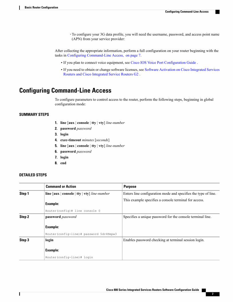
Configuring Command-Line AccessTo configure parameters to control access to the router, perform the following steps, beginning in globalconfiguration mode:
SUMMARY STEPS
1. line [aux | console | tty | vty] line-number2. password password3. login4. exec-timeout minutes [seconds]5. line [aux | console | tty | vty] line-number6. password password7. login8. end
DETAILED STEPS
PurposeCommand or Action
Enters line configuration mode and specifies the type of line.line [aux | console | tty | vty] line-numberStep 1
Example:
Router(config)# line console 0
This example specifies a console terminal for access.
Specifies a unique password for the console terminal line.password password
Example:
Router(config-line)# password 5dr4Hepw3
Step 2
Enables password checking at terminal session login.login
Example:
Router(config-line)# login
Step 3
Cisco 800 Series Integrated Services Routers Software Configuration Guide 7
Sets the time interval that the EXEC command interpreter waitsuntil user input is detected. The default is 10 minutes. Optionally,add seconds to the interval value.
exec-timeout minutes [seconds]
Example:
Router(config-line)# exec-timeout 5 30
Step 4
This example shows a timeout of 5 minutes and 30 seconds.Entering a timeout of 0 0 specifies never to time out.
Specifies a virtual terminal for remote console access.line [aux | console | tty | vty] line-number
Example:
Router(config-line)# line vty 0 4
Step 5
Specifies a unique password for the virtual terminal line.password password
Example:
Router(config-line)# password aldf2ad1
Step 6
Enables password checking at the virtual terminal session login.login
Example:
Router(config-line)# login
Step 7
Exits line configuration mode, and returns to privileged EXECmode.
end
Example:
Router(config-line)# end
Step 8
Configuring Global ParametersTo configure selected global parameters for your router, perform these steps:
SUMMARY STEPS
1. configure terminal2. hostname name3. enable secret password4. no ip domain-lookup
DETAILED STEPS
PurposeCommand or Action
Enters global configuration mode when using the console port.configure terminalStep 1
Cisco 800 Series Integrated Services Routers Software Configuration Guide8
Basic Router ConfigurationConfiguring Global Parameters
PurposeCommand or Action
Example:
If you are connecting to the router using a remote terminal, usethe following:
telnet router name or address
Login: login id
Password: *********
Router> enable
Example:
Router# configure terminal
Specifies the name for the router.hostname name
Example:
Step 2
Example:
Router(config)# hostname Router
Specifies an encrypted password to prevent unauthorized accessto the router.
enable secret password
Example:
Step 3
Example:
Router(config)# enable secret cr1ny5ho
Disables the router from translating unfamiliar words (typos)into IP addresses.
no ip domain-lookup
Example:
Step 4
Example:
Router(config)# no ip domain-lookup
Configuring WAN InterfacesConfigure the WAN interface for your router using one of the following as appropriate:
Configuring a Fast Ethernet WAN InterfaceTo configure the Fast Ethernet interface on a Cisco 861 or 881 ISR, perform these steps, beginning in globalconfiguration mode:
Cisco 800 Series Integrated Services Routers Software Configuration Guide 9
Basic Router ConfigurationConfiguring WAN Interfaces
SUMMARY STEPS
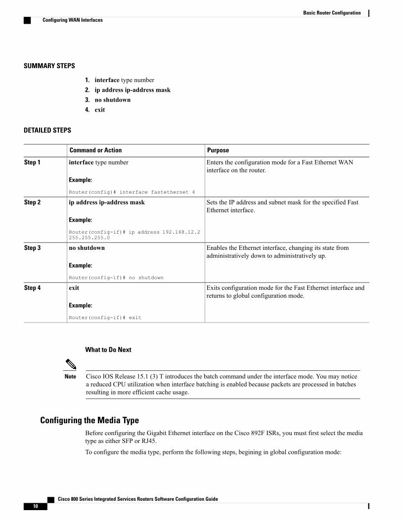
1. interface type number2. ip address ip-address mask3. no shutdown4. exit
DETAILED STEPS
PurposeCommand or Action
Enters the configuration mode for a Fast Ethernet WANinterface on the router.
interface type number
Example:
Router(config)# interface fastethernet 4
Step 1
Sets the IP address and subnet mask for the specified FastEthernet interface.
ip address ip-address mask
Example:
Router(config-if)# ip address 192.168.12.2255.255.255.0
Step 2
Enables the Ethernet interface, changing its state fromadministratively down to administratively up.
no shutdown
Example:
Router(config-if)# no shutdown
Step 3
Exits configuration mode for the Fast Ethernet interface andreturns to global configuration mode.
exit
Example:
Router(config-if)# exit
Step 4
What to Do Next
Cisco IOS Release 15.1 (3) T introduces the batch command under the interface mode. You may noticea reduced CPU utilization when interface batching is enabled because packets are processed in batchesresulting in more efficient cache usage.
Note
Configuring the Media TypeBefore configuring the Gigabit Ethernet interface on the Cisco 892F ISRs, you must first select the mediatype as either SFP or RJ45.
To configure the media type, perform the following steps, begining in global configuration mode:
Cisco 800 Series Integrated Services Routers Software Configuration Guide10
Basic Router ConfigurationConfiguring WAN Interfaces
SUMMARY STEPS
1. interface type number2. media-type {sfp | rj45}3. exit
DETAILED STEPS
PurposeCommand or Action
Enters the configuration mode for a Gigabit Ethernet WANinterface on the router.
interface type number
Example:
Router(config)# interface gigabitethernet 0
Step 1
Specifies an SFP physical connection.media-type {sfp | rj45}Step 2
Example:
Router(config-if)# media-type sfp
OR
Specifies an RJ-45 physical connection.
Example:
OR
Example:
Router(config-if)# media-type rj45
Exits configuration mode for the Gigabit Ethernet interfaceand returns to global configuration mode.
exit
Example:
Router(config-if)# exit
Step 3
Configuring a Gigabit Ethernet WAN InterfaceTo configure the Gigabit Ethernet (GE) WAN interface on a Cisco 891, 892, or 860VAE ISR, perform thesesteps, beginning in global configuration mode:
SUMMARY STEPS
1. interface type number2. ip address ip-address mask3. no shutdown4. exit
Cisco 800 Series Integrated Services Routers Software Configuration Guide 11
Basic Router ConfigurationConfiguring WAN Interfaces
DETAILED STEPS
PurposeCommand or Action
Enters the configuration mode for a Gigabit Ethernet WANinterface on the router.
interface type number
Example:
Router(config)# interface gigabitethernet 1
Step 1
Sets the IP address and subnet mask for the specified GigabitEthernet interface.
ip address ip-address mask
Example:
Router(config-if)# ip address 192.168.12.2255.255.255.0
Step 2
Enables the Ethernet interface, changing its state fromadministratively down to administratively up.
no shutdown
Example:
Router(config-if)# no shutdown
Step 3
Exits configuration mode for the Gigabit Ethernet interfaceand returns to global configuration mode.
exit
Example:
Router(config-if)# exit
Step 4
Example:
Router(config)#
Configuring a V.92 Modem InterfaceThe Cisco 891 ISR has a V.92 modem backup interface. To configure this interface, perform these steps,beginning in global configuration mode:
Cisco 800 Series Integrated Services Routers Software Configuration Guide12
Basic Router ConfigurationConfiguring WAN Interfaces
DETAILED STEPS
PurposeCommand or Action
Enters the configuration mode for a V.92 WAN interface(serial interface) on the router.
interface type number
Example:
Step 1
Example:
Router(config)# interface async 1
Sets the IP address and subnet mask for the specified V.92interface.
ip address ip-address mask
Example:
Step 2
Example:
Router(config-if)# ip address 192.168.12.2255.255.255.0
Sets the encapsulation method to point-to-point protocol(PPP) for the serial interface.
encapsulation ppp
Example:
Step 3
Example:
Router(config-if)# encapsulation ppp
Specifies that dial-on-demand routing (DDR) is supported.dialer in-band
Example:
Step 4
Example:
Router(config-if)# dialer in-band
Specifies the string (telephone number) to be used whenplacing a call from the interface.
dialer string dial-string
Example:
Step 5
Example:
Router(config-if)# dialer string 102
Configures the interface to belong to a specific dialingaccess group.
dialer-group group-number
Example:
Step 6
Cisco 800 Series Integrated Services Routers Software Configuration Guide 13
Basic Router ConfigurationConfiguring WAN Interfaces
PurposeCommand or Action
Example:
Router(config-if)# dialer-group 1
Places the line into dedicated asynchronous mode usingSerial Line Internet Protocol (SLIP) or PPP encapsulation.
async mode dedicated
Example:
Step 7
Example:
Router(config-if)# async mode dedicated
Exits configuration mode for the V.92 interface and returnsto global configuration mode.
exit
Example:
Step 8
Example:
Router(config-if)# exit
Example:
Router(config)#
Configuring a VDSL2 WAN InterfaceThe VDSL2 WAN interface is used on the Cisco 887V ISR platforms. Note that the VDSL2 WAN interfaceuses Ethernet as the Layer 2 transport mechanism.
To configure VDSL2 on the Cisco 887V ISR, perform these steps, beginning in global configuration mode:
SUMMARY STEPS
1. controller vdsl 02. interface type number3. ip address ip-address mask4. shutdown5. no shutdown6. exit
Cisco 800 Series Integrated Services Routers Software Configuration Guide14
Basic Router ConfigurationConfiguring WAN Interfaces
DETAILED STEPS
PurposeCommand or Action
Enters controller configuration mode and the controller number.controller vdsl 0Step 1
Example:There is no need to configure any VDSL2 parametersfrom CPE side. Any specific VDSL2 settings shouldbe set on the DSLAM side.
Note
Example:
Router(config)# controller vdsl 0
Enters the configuration mode for Ethernet Layer 2 transport onthe VDSL WAN interface on the router.
interface type number
Example:
Step 2
Example:
Router(config)# interface ethernet 0
Sets the IP address and subnet mask for the interface.ip address ip-address mask
Example:
Step 3
Example:
Router(config-if)# ip address 192.168.12.2255.255.255.0
Disables the interface, changing its state from administrativelyup to administratively down.
shutdown
Example:
Step 4
Example:
Router(config-if)# shutdown
Enables the interface, changing its state from administrativelydown to administratively up.
no shutdown
Example:
Step 5
Example:
Router(config-if)# no shutdown
Exits configuration mode and returns to global configurationmode.
exit
Example:
Step 6
Cisco 800 Series Integrated Services Routers Software Configuration Guide 15
Basic Router ConfigurationConfiguring WAN Interfaces
PurposeCommand or Action
Example:
Router(config-if)# exit
Configuring ADSL or VDSL on Cisco 860VAE and 880VA Multimode ISRsThis section contains the following topics:
Overview of Cisco 860VAE, 886VA, and 887VA Multimode ISRsThe Cisco customer premise equipment (CPE) Cisco 866VAE, 867VAE, 866VAE-K9, 867VAE-K9, 886VAand 887VA integrated services routers (ISRs) support asymmetric digital subscriber line (ADSL) 1/2/2+ andvery high speed digital subscriber line 2 (VDSL2) transmission modes, also called multimode.
The 866VAE and 886VA support xDSL over ISDN. The 867VAE and 887VA support xDSL over a plainold telephone system (POTS).
Note
The default CPE operating mode is auto. Auto mode means that the CPE trains up to the mode configured onthe digital subscriber line access multiplexer (DSLAM), ADSL1/2/2+, or VDSL2.
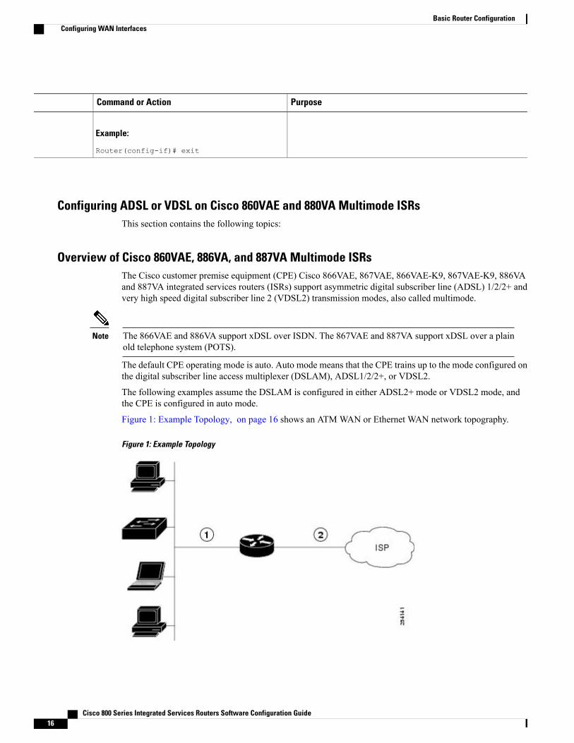
The following examples assume the DSLAM is configured in either ADSL2+ mode or VDSL2 mode, andthe CPE is configured in auto mode.
Figure 1: Example Topology, on page 16 shows an ATMWAN or Ethernet WAN network topography.
Figure 1: Example Topology
Cisco 800 Series Integrated Services Routers Software Configuration Guide16
Basic Router ConfigurationConfiguring WAN Interfaces
ATMWANinterface—ADSL 1/2/2+mode or
Ethernet WANInterface—VDSL2mode
2Fast Ethernet LANinterface or
Gigabit Ethernet LANinterface
1
A DSLAM in Layer 1 mode may be configured for auto mode. A DSLAM in Layer 2 mode must beconfigured for ATM mode or packet transfer mode (PTM).
Note
Cisco 886VA and 887VA allow a maximum of four permanent virtual circuits (PVCs).Note
Cisco 866VAE, Cisco 867VAE, Cisco 866VAE-K9, and Cisco 867VAE-K9 ISRs allow a maximum oftwo PVCs.
Note
ADSL2/2+ Annex M Mode on Over POTS VDSL2/ADSL Multimode Annex A SKUsAnnex M is an enhancement of the G.992.3 standard that doubles the upstream bandwidth by "borrowing"32 additional tones from the downstream frequency range. This feature enables service providers to provisionsymmetric data rates for ADSL2 and ADSL2+ services with data rates up to 2 Mbps.
Cisco IOS Release 15.2(1)T adds support for enabling Annex M data structures on Cisco 887VA platformsand Annex A data structures on Cisco 887VA-M platforms. This features allows both Annex A and AnnexM structures to be run on the same platform with a performance tradeoff for the annex that is not optimizedfor the device. With this feature implementation, the modes supported on Annex A platforms are the same asthe modes supported on Annex M platforms (887VA-M and EHWIC-1DSL-VA-M). When digital subscriberline access multiplexer (DSLAM) supports Annex M, Annex Mmode takes precedence over Annex A mode.
Cisco 867VAE and 867VAE-K9 require Cisco IOS Release 15.1(4)M2 or 15.2(2)T or later to use thisfeature.
Note
For information on configuring AnnexM data structures on Annex A platforms, see the, Enabling ADSL2/2+Annex M Mode on Over POTS VDSL2/ADSL Multimode Annex A SKUs, on page 30.
Configuring Seamless Rate AdaptionADSL connections can be dropped due to a number of reasons, such as crosstalk, changes in noise margin,temperature changes, or interference. ADSL2 addresses these problems by adapting the data rate in real-time.Seamless rate adaptation (SRA) enables the ADSL2 system to change the data rate of the connection duringoperation without any service interruption or bit errors.
Cisco 800 Series Integrated Services Routers Software Configuration Guide 17
Basic Router ConfigurationConfiguring WAN Interfaces
These features are not currently available on the 866VAE, 867VAE, 866VAE-K9, and 867VAE-K9.Note
For information on configuring SRA, see the Enabling Seamless Rate Adaption , on page 31.
Configuring UBR+UBR is typically used for data communications applications, such as file transfer and email. UBR is a besteffort service and is the lowest class of service in the hierarchy. There are no guarantees to the actual bandwidthallowed. Therefore, UBR virtual circuits (VCs) are susceptible to a large number of cell drops or a high celltransfer delay as cells move from the source to the destination. UBR has no bounds on Cell Delay VariationTolerance (CDVT) and is only a best effort service.
UBR+ is a special ATM service class developed by Cisco. UBR defines only peak cell rate (PCR); however,UBR+ defines a minimum guaranteed cell rate (MCR) and (on the switch) a cell delay variation tolerance(CDVT).
On Cisco IOS versions 15.2(1)T and later, UBR+ is compatable with CiscoMultimode 886VA and 887VArouters.
Note
These features are not currently available on the 866VAE, 867VAE, 866VAE-K9, and 867VAE-K9.Note
For information on configuring UBR+, see the Configuring UBR+, on page 33.
Configuring ADSL Mode
Configuration tasks
Perform the following tasks to configure ADSL mode:
Configuring ADSL Auto Mode
Perform these steps to configure the DSL controller to auto mode, starting in global configuration mode.
Configure the DSLAM in ADSL 1/2/2+ mode prior to configuring the router.Note
Example:When configured in auto, the operating mode does notappear in the show running command.
Note
Example:
Router(config-controller)# operating modeauto
Exits the configuration mode and enters EXEC mode.endStep 5
Example:A reload is required after changing mode between adsland vdsl for Cisco 866VAE, Cisco 867VAE, Cisco866VAE-K9, and Cisco 867VAE-K9.
Note
Example:
Router(config-controller)# end
Example:
Router#
Configuring CPE and Peer for ADSL Mode
When configuring for ADSL, the ATM main interface or ATM sub-interface must be configured with a PVCand an IP address, perform a no shutdown command on the interface if needed.
Cisco 800 Series Integrated Services Routers Software Configuration Guide 19
Basic Router ConfigurationConfiguring WAN Interfaces
Configuring the ATM CPE sidePerform the following steps to configure the ATM CPE side, starting in global configuration mode.
SUMMARY STEPS
1. interface type number2. no shutdown3. interface atm0.1 point-to-point4. ip address ip-address mask5. pvc [name] vpi/vci6. protocol protocol {protocol-address [virtual-template] | inarp} [[no] broadcast | disable-check-subnet
| [no] enable-check-subnet]7. end
DETAILED STEPS
PurposeCommand or Action
Enters configuration mode for the ATMWANinterface (ATM0).
interface type number
Example:
Router(config)# interface atm0
Step 1
Enables the configuration changes to the ATMinterface.
Enters IP address and subnet mask.ip address ip-address mask
Example:
Router(config-subif)# ip address 30.0.0.2255.255.255.0
Step 4
Creates or assigns a name to an ATMPVC and entersthe ATM virtual circuit configuration mode.
pvc [name] vpi/vci
Example:
Router(config-subif)# pvc 13/32
Step 5
Configures a static map for an ATM PVC.protocol protocol {protocol-address [virtual-template] |inarp} [[no] broadcast | disable-check-subnet | [no]enable-check-subnet]
Step 6
Example:
Router(config-if-atm-vc)# protocol ip 30.0.0.1broadcast
Exits the configurationmode and enters EXECmode.end
Example:
Router(config-if-atm-vc)# end
Step 7
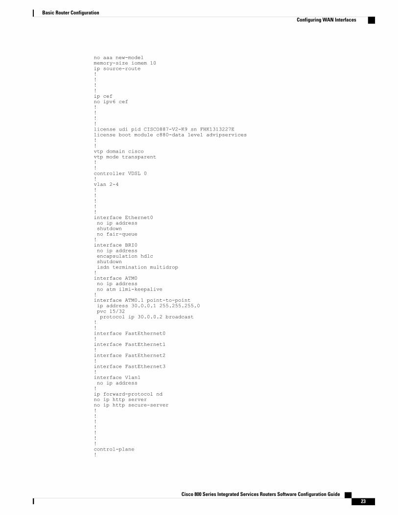
ADSL Configuration Example
The following example shows a typical ADSL2+ configuration set to auto mode. Outputs in bold are critical.
Router# show runningBuilding configuration...Current configuration : 1250 bytes!! Last configuration change at 02:07:09 UTC Tue Mar 16 2010!version 15.1no service padservice timestamps debug datetime msecservice timestamps log datetime msecno service password-encryption!hostname Router!boot-start-markerboot-end-marker!!
Cisco 800 Series Integrated Services Routers Software Configuration Guide22
Basic Router ConfigurationConfiguring WAN Interfaces
no aaa new-modelmemory-size iomem 10ip source-route!!!!ip cefno ipv6 cef!!!!license udi pid CISCO887-V2-K9 sn FHK1313227Elicense boot module c880-data level advipservices!!vtp domain ciscovtp mode transparent!!controller VDSL 0!vlan 2-4!!!!!interface Ethernet0no ip addressshutdownno fair-queue!interface BRI0no ip addressencapsulation hdlcshutdownisdn termination multidrop!interface ATM0no ip addressno atm ilmi-keepalive!interface ATM0.1 point-to-pointip address 30.0.0.1 255.255.255.0pvc 15/32protocol ip 30.0.0.2 broadcast
!!interface FastEthernet0!interface FastEthernet1!interface FastEthernet2!interface FastEthernet3!interface Vlan1no ip address!ip forward-protocol ndno ip http serverno ip http secure-server!!!!!!!control-plane!
Cisco 800 Series Integrated Services Routers Software Configuration Guide 23
Basic Router ConfigurationConfiguring WAN Interfaces
!line con 0no modem enableline aux 0line vty 0 4logintransport input all!exception data-corruption buffer truncateend
Verifying ADSL Configuration
Verify that the configuration is set properly by using the show controller vdsl 0 command from the privilegedEXEC mode. Outputs in bold are critical.
Router# show controller vdsl 0Controller VDSL 0 is UPDaemon Status: Up
When configured in auto, the operating mode does notappear in the show running command.
Note
Cisco 800 Series Integrated Services Routers Software Configuration Guide 25
Basic Router ConfigurationConfiguring WAN Interfaces
PurposeCommand or Action
Exits the configuration mode and enters EXEC mode.endStep 3
Example:
Router(config-controller)# endRouter#
A reload is required after changing the mode on the Cisco866VAE, Cisco 867VAE, Cisco 866VAE-K9, and Cisco867VAE-K9.
Note
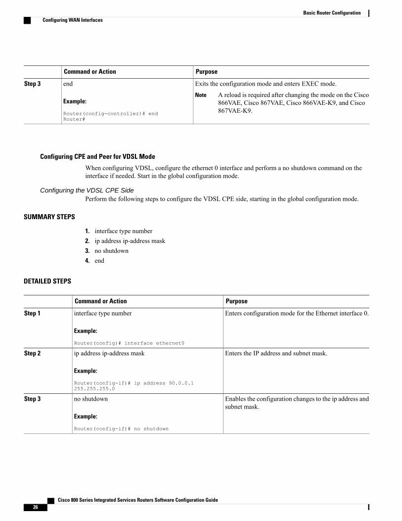
Configuring CPE and Peer for VDSL Mode
When configuring VDSL, configure the ethernet 0 interface and perform a no shutdown command on theinterface if needed. Start in the global configuration mode.
Configuring the VDSL CPE SidePerform the following steps to configure the VDSL CPE side, starting in the global configuration mode.
SUMMARY STEPS
1. interface type number2. ip address ip-address mask3. no shutdown4. end
DETAILED STEPS
PurposeCommand or Action
Enters configuration mode for the Ethernet interface 0.interface type number
Example:
Router(config)# interface ethernet0
Step 1
Enters the IP address and subnet mask.ip address ip-address mask
Example:
Router(config-if)# ip address 90.0.0.1255.255.255.0
Step 2
Enables the configuration changes to the ip address andsubnet mask.
no shutdown
Example:
Router(config-if)# no shutdown
Step 3
Cisco 800 Series Integrated Services Routers Software Configuration Guide26
Basic Router ConfigurationConfiguring WAN Interfaces
PurposeCommand or Action
Exits the configuration mode and enters EXEC mode.end
Example:
Router(config-if)# end
Step 4
Configuring the VDSL Peer SidePerform the following steps to configure the VDSL Peer side, starting in the global configuration mode.
SUMMARY STEPS
1. interface type number2. ip address ip-address mask3. no shutdown4. end
DETAILED STEPS
PurposeCommand or Action
Enters configuration mode for the Ethernet interface 0.interface type number
Example:
Router(config)# interface ethernet0
Step 1
Configures the IP address and subnet mask.ip address ip-address mask
Example:
Router(config-if)# ip address 90.0.0.2255.255.255.0
Step 2
Enables the configuration changes to the IP address andsubnet mask.
no shutdown
Example:
Router(config-if)# no shutdown
Step 3
Exits the configuration mode and enters EXEC mode.end
Example:
Router(config-if)# end
Step 4
Cisco 800 Series Integrated Services Routers Software Configuration Guide 27
Basic Router ConfigurationConfiguring WAN Interfaces
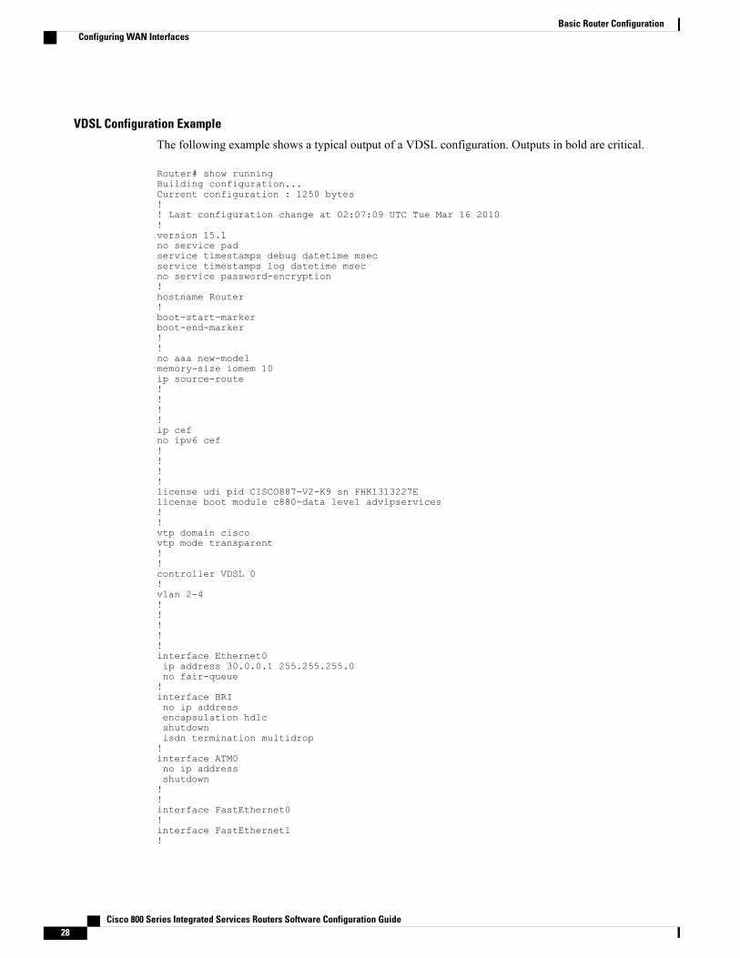
VDSL Configuration Example
The following example shows a typical output of a VDSL configuration. Outputs in bold are critical.
Router# show runningBuilding configuration...Current configuration : 1250 bytes!! Last configuration change at 02:07:09 UTC Tue Mar 16 2010!version 15.1no service padservice timestamps debug datetime msecservice timestamps log datetime msecno service password-encryption!hostname Router!boot-start-markerboot-end-marker!!no aaa new-modelmemory-size iomem 10ip source-route!!!!ip cefno ipv6 cef!!!!license udi pid CISCO887-V2-K9 sn FHK1313227Elicense boot module c880-data level advipservices!!vtp domain ciscovtp mode transparent!!controller VDSL 0!vlan 2-4!!!!!interface Ethernet0ip address 30.0.0.1 255.255.255.0no fair-queue!interface BRIno ip addressencapsulation hdlcshutdownisdn termination multidrop!interface ATM0no ip addressshutdown!!interface FastEthernet0!interface FastEthernet1!
Cisco 800 Series Integrated Services Routers Software Configuration Guide28
Basic Router ConfigurationConfiguring WAN Interfaces
interface FastEthernet2!interface FastEthernet3!interface Vlan1no ip address!ip forward-protocol ndno ip http serverno ip http secure-server!!!!!!!control-plane!!line con 0no modem enableline aux 0line vty 0 4logintransport input all!exception data-corruption buffer truncateend
Verifying VDSL Configuration
Verify the configuration is set properly by using the show controller vdsl 0 command from privileged EXECmode. Outputs in bold are critical.
Router# show controller vdsl 0Controller VDSL 0 is UPDaemon Status: Up
Ping the peer to confirm that CPE to peer configuration is setup correctly.
Router# ping 30.0.0.2 rep 20Type escape sequence to abort.Sending 20, 100-byte ICMP Echos to 30.0.0.2, timeout is 2 seconds:!!!!!!!!!!!!!!!!!!!!Success rate is 100 percent (20/20), round-trip min/avg/max = 20/22/28 msRouter#
Enabling ADSL2/2+ Annex M Mode on Over POTS VDSL2/ADSL Multimode Annex A SKUs
This feature requires Cisco IOS Release 15.2(1)T or a later.Note
Cisco 867VAE and 867VAE-K9 require Cisco IOS Release 15.1(4)M2 or 15.2(2)T or later to use thisfeature.
Note
Configuring ADSL2/2+ Annex M mode on Over POTS VDSL2/ADSL Multimode Annex A SKUs.
SUMMARY STEPS
1. enable2. configure terminal3. controller vdsl 04. operating mode {adsl1 | adsl2 annex a | annex m | adsl2+ annex a | annex m] | ansi | auto| vdsl2}
Cisco 800 Series Integrated Services Routers Software Configuration Guide30
Basic Router ConfigurationConfiguring WAN Interfaces
DETAILED STEPS
PurposeCommand or Action
Enables privileged EXEC mode.enableStep 1
Example:
Router> enable
• Enter your password if prompted.
Enters global configuration mode.configure terminal
Example:
Router# configure terminal
Step 2
Enters configuration mode for the VDSL controller.controller vdsl 0Step 3
asdl1—Configures operation in ITU G.992.1 Annex A full-rate mode.operating mode {adsl1 | adsl2 annexa | annex m | adsl2+ annex a | annexm] | ansi | auto| vdsl2}
Step 4
adsl2—Configures operation in ADSL2 operating mode-ITU G.992.3 Annex A,Annex L, and Annex M. If an Annex operating mode is not chosen, Annex A,
Example:
Router(config-controller)#operating mode adsl2+ annex m
Annex L, and AnnexM are enabled. The final mode is decided by negotiation withthe DSL access multiplexer (DSLAM).
adsl2+—Configures operation in ADSL2+ mode-ITU G.992.5 Annex A andAnnexM. If an Annex A operating mode is not chosen, both Annex and Annex Mis enabled. The final mode is decided by negotiation with DSLAM.
ansi—Configures a router to operate in ANSI full-rate mode-ANSI T1.413.
auto—Default setting. Configures the router so that the DSLAM automaticallypicks the DSL operatingmode, in the sequence described in the "Usage Guidelines"section. All supported modes are enabled.
vdsl2—Configures operation in ITU G.993.2 mode.
annex a, m—(Optional) If the annex option is not specified, both Annex A andAnnex M are enabled. The final mode is decided by negotiation with the DigitalSynchronous Line Access Multiplexer (DSLAM).
Enabling Seamless Rate AdaptionTo enable SRA, perform the following steps.
SRA mode is disabled by default.Note
SRA requires Cisco IOS Release 15.2(1)T or a later release.Note
Cisco 800 Series Integrated Services Routers Software Configuration Guide 31
Basic Router ConfigurationConfiguring WAN Interfaces
These features are not currently available on the Cisco 866VAE, 867VAE, 866VAE-K9, or 867VAE-K9.Note
Enters global configuration mode.configure terminal
Example:
Router# configure terminal
Step 2
Enters controller configuration mode. Use the controller vdslcommand in global configuration mode. This command does nothave a no form.
controller vdsl x/y/z
Example:
Router(config)# controller vdsl 0/0/0
Step 3
x—Defines the network module.
y—Defines the slot number.
z—Defines the port number.
Enables SRA mode.sraStep 4
Example:
router(config-controller)# sra
Use the no form of the command to disable SRA.
Example Configuration: Seamless Rate Adaption
The following example enables SRA on a VDSL line:
!!!rotuer>enablerouter# configure terminal
Cisco 800 Series Integrated Services Routers Software Configuration Guide32
Basic Router ConfigurationConfiguring WAN Interfaces
Enter configuration commands, one per line. End with CNTL/Zrouter(config)# controller vdsl 0router(config-controller)# srarouter(config-controller)# endrouter#!!!
Configuring UBR+Perform the following steps to configure UBR+.
Cisco IOS Release 15.2(1)T or a later release is required to run UBR+ on Cisco 886VA, 887VA, and887VA-M routers.
Note
These features are not currently available on the Cisco 866VAE, 867VAE, 866VAE-K9, or 867VAE-K9.Note
Enters global configuration mode.configure terminal
Example:
Router# configure terminal
Step 2
Configures unspecified bit rate (UBR) quality of service (QoS) and specifies theoutput peak cell rate and output minimum guaranteed cell rate for an ATM
To remove the UBR+ parameters, use the no form of this command.
output-pcr—The output peak cell rate (PCR) in kbps.
output-mcr—The output minimum guaranteed cell rate in kbps.
input-pcr—(Optional for SVCs only) The input PCR in kbps. If this value isomitted, the input-pcr equals the output-pcr.
Cisco 800 Series Integrated Services Routers Software Configuration Guide 33
Basic Router ConfigurationConfiguring WAN Interfaces
PurposeCommand or Action
input-mcr—(Optional for SVCs only) The input minimum guaranteed cell ratein kbps. If this value is omitted, the input-mcr equals the output-mcr.
UBR+ Example
The following example configures UBR+ PVC on a DSL line:
interface atm 0/0pvc 4/100ubr+ 2304 2304
The following example specifies the output-pcr argument for an ATM PVC to be 100000 kbps and the output-mcrto be 3000 kbps:
pvc 1/32ubr+ 100000 3000
The following example specifies the output-pcr, output-mcr, input-pcr, and input-mcr arguments for an ATMSVC to be 10000 kbps, 3000 kbps, 9000 kbps, and 1000 kbps, respectively:
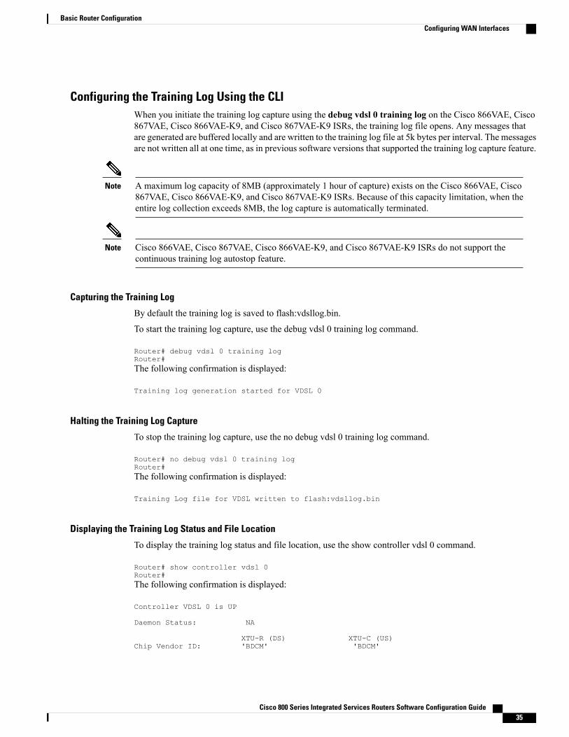
Configuring the Training Log Using the CLIWhen you initiate the training log capture using the debug vdsl 0 training log on the Cisco 866VAE, Cisco867VAE, Cisco 866VAE-K9, and Cisco 867VAE-K9 ISRs, the training log file opens. Any messages thatare generated are buffered locally and are written to the training log file at 5k bytes per interval. The messagesare not written all at one time, as in previous software versions that supported the training log capture feature.
A maximum log capacity of 8MB (approximately 1 hour of capture) exists on the Cisco 866VAE, Cisco867VAE, Cisco 866VAE-K9, and Cisco 867VAE-K9 ISRs. Because of this capacity limitation, when theentire log collection exceeds 8MB, the log capture is automatically terminated.
Note
Cisco 866VAE, Cisco 867VAE, Cisco 866VAE-K9, and Cisco 867VAE-K9 ISRs do not support thecontinuous training log autostop feature.
Note
Capturing the Training Log
By default the training log is saved to flash:vdsllog.bin.
To start the training log capture, use the debug vdsl 0 training log command.
Router# debug vdsl 0 training logRouter#The following confirmation is displayed:
Training log generation started for VDSL 0
Halting the Training Log Capture
To stop the training log capture, use the no debug vdsl 0 training log command.
Router# no debug vdsl 0 training logRouter#The following confirmation is displayed:
Training Log file for VDSL written to flash:vdsllog.bin
Displaying the Training Log Status and File Location
To display the training log status and file location, use the show controller vdsl 0 command.
Router# show controller vdsl 0Router#The following confirmation is displayed:
Training Log : StoppedTraining Log Filename : flash:vdsllog.bin
Configuring a G.SHDSL WAN Interface in ATM modePerform the following steps to configure G.SHDSL on the Cisco 888 ISR perform these steps, beginning inglobal configuration mode.
Cisco 800 Series Integrated Services Routers Software Configuration Guide36
Basic Router ConfigurationConfiguring WAN Interfaces
Cisco 800 Series Integrated Services Routers Software Configuration Guide 39
Basic Router ConfigurationConfiguring WAN Interfaces
ip address 10.10.10.1 255.255.255.0no atm ilmi-keepalivepvc 0/31protocol ip 10.10.10.5 broadcastencapsulation aal5snap!
Configuring a G.SHDSL WAN Interface in EFM modeTo configure G.SHDSL on the Cisco 888E ISR, perform Configuring Cisco G.SHDSL EFMHWICs in CiscoRouters at:
Configuring the Cellular Wireless WAN InterfaceThe Cisco 880 series and Cisco 810 series ISRs provide a third generation (3G) wireless interface for use overGlobal System for Mobile Communications (GSM) and code division multiple access (CDMA) networks.The interface is a 34-mm PCMCIA slot for Cisco 880 series.
Its primary application is WAN connectivity as a backup data link for critical data applications. However, the3G wireless interface can also function as the primary WAN connection for the router.
To configure the 3G cellular wireless interface, follow these guidelines and procedures:
Prerequisites for Configuring the 3G Wireless Interface
The following are prerequisites to configuring the 3G wireless interface:
• You must have wireless service from a carrier, and you must have network coverage where your routerwill be physically placed. For a complete list of supported carriers, see the data sheet at:
• You must subscribe to a service plan with a wireless service provider and obtain a SIM card (GSMmodem only) from the service provider.
• Youmust check your LEDs for signal strength, as described in Table 4: Front Panel LED Signal StrengthIndications, on page 41.
• You should be familiar with the Cisco IOS software, beginning with Cisco NX-OS Release 4.1 or later.For Cisco 3G Wireless support, see the Cisco IOS documentation.
• To configure your GSM data profile, you need the following information from your service provider:
◦Username
◦Password
◦Access point name (APN)
• To configure your CDMA data profile for manual activation, you need the following information fromyour service provider:
Cisco 800 Series Integrated Services Routers Software Configuration Guide40
Basic Router ConfigurationConfiguring WAN Interfaces
Table 4: Front Panel LED Signal Strength Indications
Signal StrengthLED ColorLED
No service available and no RSSIdetected
AmberP3G RSSI1
High RSSI (–69 dBm or higher)Solid green
Medium RSSI (–89 to –70 dBm)Fast (16 Hz) blinking green
Low to medium RSSI (–99 to –90dBm), minimum level for a reliableconnection
Slow (1 Hz) blinking green
Low RSSI (less than –100 dBm)Off
1 3G RSSI = 3G receive signal strength indication.
Restrictions for Configuring the Cellular Wireless Interface
The following restrictions apply to configuring the Cisco 3G wireless interface:
• A data connection can be originated only by the 3G wireless interface. Remote dial-in is not supported.
• Because of the shared nature of wireless communications, the experienced throughput varies dependingon the number of active users or the amount of congestion in a given network.
• Cellular networks have higher latency than wired networks. Latency rates depend on the technology andcarrier. Latency may be higher when there is network congestion.
• VoIP is not currently supported.
• Any restrictions that are part of the terms of service from your carrier also apply to the Cisco 3Gwirelessinterface.
• Cisco 880G ISR does not support online insertion and removal (OIR) of 3G modems. To replace amodem with another modem of the same type, use the Cisco CLI to enter the shutdown command onthe cellular interface before you replace the modems. =
•When a 3G modem is removed, the show interface cellular 0, show run, and show version commandoutputs still display cellular interface related information. The show interface command displays thefollowing message, all other show commands have empty outputs.
3G Modem not inserted
Cisco 800 Series Integrated Services Routers Software Configuration Guide 41
Basic Router ConfigurationConfiguring WAN Interfaces
• You can configure the cellular interface when the 3G modem is removed. However, the configurationis not effective until the 3Gmodem is inserted. The following message is shown when trying to configurethe cellular interface while the modem is absent.
Router(config)# interface cellular 0Warning: 3G Modem is not insertedConfiguration will not be effective until modem is inserted =
• Inserting a different type of modem than was previously removed requires configuration changes andyou must reload the system.
Data Account Provisioning
To provision your modem, you must have an active wireless account with a service provider. A SIM cardmust be installed in a GSM 3G wireless card.
Note
To provision your data account, follow these procedures:
Verifying Signal Strength and Service AvailabilityTo verify the signal strength and service availability on your modem, use the following commands in privilegedEXEC mode.
This feature requires Cisco IOS Release 15.2(1)T or a later.Note
Cisco 867VAE and 867VAE-K9 require Cisco IOS Release 15.1(4)M2 or 15.2(2)T or later to use thisfeature.
Note
SUMMARY STEPS
1. show cellular 0 network2. show cellular 0 hardware3. show cellular 0 connection4. show cellular 0 radio5. show cellular 0 profile6. show cellular 0 security7. show cellular 0 all
Cisco 800 Series Integrated Services Routers Software Configuration Guide42
Basic Router ConfigurationConfiguring WAN Interfaces
DETAILED STEPS
PurposeCommand or Action
Displays information about the carrier network, cell site, andavailable service.
show cellular 0 network
Example:
Router# show cellular 0 network
Step 1
Displays the cellular modem hardware information.show cellular 0 hardware
Example:
Router# show cellular 0 hardware
Step 2
Displays the current active connection state and data statistics.show cellular 0 connection
Example:
Router# show cellular 0 connection
Step 3
Shows the radio signal strength.show cellular 0 radioStep 4
Example:
Router# show cellular 0 radio
The RSSI should be better than –90 dBm for steadyand reliable connection.
Note
Shows information about the modem data profiles created.show cellular 0 profile
Example:
Router# show cellular 0 profile
Step 5
Shows the security information for the modem, such as SIMand modem lock status.
show cellular 0 security
Example:
Router# show cellular 0 security
Step 6
Shows consolidated information about themodem. The profilesthat were created, the radio signal strength, the networksecurity, and so on.
show cellular 0 all
Example:
Router# show cellular 0 all
Step 7
Configuring a GSM Modem Data ProfileTo configure or create a new modem data profile, enter the cellular 0 gsm profile create <profile number><apn> <authentication> <username> <password> command in privileged EXEC mode. See Table 5:Modem Data Profile Parameters , on page 44 for details about the command parameters.
Cisco 800 Series Integrated Services Routers Software Configuration Guide 43
Basic Router ConfigurationConfiguring WAN Interfaces
Table 5: Modem Data Profile Parameters , on page 44 lists the modem data profile parameters.
Table 5: Modem Data Profile Parameters
Number for the profile that you are creating. You cancreate up to 16 profiles.
profile number
Access point name. You must get this informationfrom your service provider.
apn
Type of authentication, for example, CHAP, PAP.authentication
Username provided by your service provider.username
Password provided by your service provider.password
CDMA Modem Activation and ProvisioningActivation procedures may differ, depending upon your carrier. Consult your carrier, and perform one of thefollowing procedures as appropriate:
• Manual activation
• Activation using over the air service provisioning
Table 6: CDMA Modem Activation and Provisioning, on page 44 lists the activation and provisioningprocesses supported by different wireless carriers.
Table 6: CDMA Modem Activation and Provisioning
CarrierActivation and Provisioning Process
SprintManual Activation using MDN, MSID, MSL
Verizon WirelessOTASP2 Activation
SprintIOTA3 for Data Profile refresh
2 OTASP = Over the Air Service Provisioning.3 IOTA = Internet Over the Air.
Manual Activation
You must have valid mobile directory number (MDN), mobile subsidy lock (MSL), and mobile stationidentifier (MSID) information from your carrier before you start this procedure.
Note
To configure a modem profile manually, use the following command, beginning in EXEC mode:
cellular 0 cdma activate manual mdn msid sid nid msl
Cisco 800 Series Integrated Services Routers Software Configuration Guide44
Basic Router ConfigurationConfiguring WAN Interfaces
Besides being activated, the modem data profile is provisioned through the Internet Over the Air (IOTA)process. The IOTA process is initiated automatically when you use the cellular cdma activate manual command.
The following is a sample output from this command:
router# cellular 0 cdma activate manual 1234567890 1234567890 1234 12 12345NAM 0 will be configured and will become ActiveModem will be activated with following ParametersMDN :1234567890; MSID :1234567890; SID :1234; NID 12:Checking Current Activation StatusModem activation status: Not ActivatedBegin ActivationAccount activation - Step 1 of 5Account activation - Step 2 of 5Account activation - Step 3 of 5Account activation - Step 4 of 5Account activation - Step 5 of 5Secure Commit Result: SucceedDone Configuring - Resetting the modemThe activation of the account is CompleteWaiting for modem to be ready to start IOTABeginning IOTArouter#*Feb 6 23:29:08.459: IOTA Status Message Received. Event: IOTA Start, Result: SUCCESS*Feb 6 23:29:08.459: Please wait till IOTA END message is received*Feb 6 23:29:08.459: It can take up to 5 minutes*Feb 6 23:29:27.951: OTA State = SPL unlock, Result = Success*Feb 6 23:29:32.319: OTA State = Parameters committed to NVRAM, Result = Success*Feb 6 23:29:40.999: Over the air provisioning complete; Result:Success*Feb 6 23:29:41.679: IOTA Status Message Received. Event: IOTA End, Result: SUCCESS
The IOTA start and end must have “success” as the resulting output. If you receive an error message, you canrun IOTA independently by using the cellular cdma activate iota command.
Your carrier may require periodic refreshes of the data profile. Use the following command to refresh the dataprofile:
cellular cdma activate iota
Activating with Over-the-Air Service Provisioning
To provision and activate your modem using Over-the-Air Service Provisioning (OTASP), use the followingcommand, beginning in EXEC mode.
You need to obtain the phone number for use with this command from your carrier. The standard OTASPcalling number is *22899.
Note
The following is a sample output from this command:
router# cellular 0 cdma activate otasp *22899Beginning OTASP activationOTASP number is *22899steelers_c881G#OTA State = SPL unlock, Result = Successrouter#OTA State = PRL downloaded, Result = SuccessOTA State = Profile downloaded, Result = SuccessOTA State = MDN downloaded, Result = SuccessOTA State = Parameters committed to NVRAM, Result = SuccessOver the air provisioning complete; Result:Success
Cisco 800 Series Integrated Services Routers Software Configuration Guide 45
Basic Router ConfigurationConfiguring WAN Interfaces
Configuring a Cellular Interface
To configure the cellular interface, enter the following commands, beginning in privileged EXEC mode.
The PPP Challenge Handshake Authentication Protocol (CHAP) authentication parameters that you usein this procedure must be the same as the username and password provided by your carrier and configuredonly under the GSM profile. CDMA does not require a username or password.
Note
SUMMARY STEPS
1. configure terminal2. interface cellular 03. encapsulation ppp4. ppp chap hostname host5. ppp chap password 0 password6. asynchronous mode interactive7. ip address negotiated
DETAILED STEPS
PurposeCommand or Action
Enters global configuration mode from the terminal.configure terminal
Example:
Router# configure terminal
Step 1
Specifies the cellular interface.interface cellular 0
Example:
Router (config)# interface cellular 0
Step 2
Specifies PPP encapsulation for an interface configured fordedicated asynchronousmode or dial-on-demand routing (DDR).
encapsulation ppp
Example:
Router (config-if)# encapsulation ppp
Step 3
Defines an interface-specific Challenge HandshakeAuthentication Protocol (CHAP) hostname. This must matchthe username given by the carrier. Applies to GSM only.
Cisco 800 Series Integrated Services Routers Software Configuration Guide46
Basic Router ConfigurationConfiguring WAN Interfaces
PurposeCommand or Action
Defines an interface-specific CHAP password. This must matchthe password given by the carrier.
ppp chap password 0 password
Example:
Router (config-if)# ppp chap password 0cisco
Step 5
Returns a line from dedicated asynchronous network mode tointeractive mode, enabling the slip and ppp commands inprivileged EXEC mode.
asynchronous mode interactive
Example:
Router (config-if)# asynchronous modeinteractive
Step 6
Specifies that the IP address for a particular interface is obtainedvia PPP and IPCP address negotiation.
ip address negotiated
Example:
Router (config-if)# ip address negotiated
Step 7
What to Do Next
When the cellular interface requires a static IP address, the address may be configured as ip addressnegotiated. Through IP Control Protocol (IPCP), the network ensures that the correct static IP address isallocated to the device. If a tunnel interface is configured with the ip address unnumbered cellular interfacecommand, the actual static IP address must be configured under the cellular interface, in place of ip addressnegotiated. For a sample cellular interface configuration, see the Basic Cellular Interface Configuration,on page 50.
Note
Configuring DDR
Perform these steps to configure dial-on-demand routing (DDR) for the cellular interface.
Cisco 800 Series Integrated Services Routers Software Configuration Guide 47
Basic Router ConfigurationConfiguring WAN Interfaces
SUMMARY STEPS
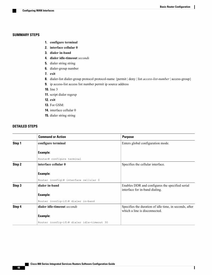
1. configure terminal2. interface cellular 03. dialer in-band4. dialer idle-timeout seconds5. dialer string string6. dialer-group number7. exit8. dialer-list dialer-group protocol protocol-name {permit | deny | list access-list-number | access-group}9. ip access-list access list number permit ip source address10. line 311. script dialer regexp12. exit13. For GSM:14. interface cellular 015. dialer string string
DETAILED STEPS
PurposeCommand or Action
Enters global configuration mode.configure terminal
Example:
Router# configure terminal
Step 1
Specifies the cellular interface.interface cellular 0
Example:
Router (config)# interface cellular 0
Step 2
Enables DDR and configures the specified serialinterface for in-band dialing.
dialer in-band
Example:
Router (config-if)# dialer in-band
Step 3
Specifies the duration of idle time, in seconds, afterwhich a line is disconnected.
dialer idle-timeout seconds
Example:
Router (config-if)# dialer idle-timeout 30
Step 4
Cisco 800 Series Integrated Services Routers Software Configuration Guide48
Basic Router ConfigurationConfiguring WAN Interfaces
PurposeCommand or Action
Specifies the number or string to dial. Use the nameof the chat script here.
dialer string string
Example:
Router (config-if)# dialer string gsm
Step 5
Specifies the number of the dialer access group towhich a specific interface belongs.
dialer-group number
Example:
Router (config-if)# dialer-group 1
Step 6
Enters the global configuration mode.exit
Example:
Router (config-if)# exit
Step 7
Creates a dialer list for traffic of interest and permitsaccess to an entire protocol.
Specifies the cellular interface.interface cellular 0
Example:
Router (config)# interface cellular 0
Step 14
Specifies the dialer script (defined using the chat scriptcommand).
dialer string string
Example:
Router (config)# dialer string gsm
Step 15
Configuring Data Dedicated Transmission Mode (DDTM)
On CDMA modems, data transmission is disrupted by incoming voice calls if data dedicated transmissionmode (DDTM) is disabled. You can enable DDTM mode so the modem ignores incoming voice calls.
To enable DDTM on a CDMA modem, use the cdma ddtm command in configuration mode.
This command is enabled by default. You can disable this feature by using the no cdma ddtm command.
When DDTM is enabled, only voice calls are blocked for the MC5728v modems. On the AC597E andMC5725 and MC 5727, incoming SMS messages are also blocked.
Note
Examples for Configuring Cellular Wireless Interfaces
This section provides the following configuration examples:
Basic Cellular Interface ConfigurationThe following example shows how to configure a gsm cellular interface to be used as a primary WANconnection. It is configured as the default route.
Cisco 800 Series Integrated Services Routers Software Configuration Guide50
Basic Router ConfigurationConfiguring WAN Interfaces
!interface Cellular0ip address negotiatedencapsulation pppdialer in-banddialer string gsmdialer-group 1async mode interactiveppp chap hostname [email protected] chap password 0 ciscoppp ipcp dns request!ip route 0.0.0.0 0.0.0.0 Cellular0!!access-list 1 permit anydialer-list 1 protocol ip list 1!line 3exec-timeout 0 0script dialer gsmloginmodem InOutThe following example shows how to configure a cdma cellular interface to be used as a primary. It is configuredas the default route.
Tunnel over Cellular Interface ConfigurationThe following example shows how to configure the static IP address when a tunnel interface is configuredwith the ip address unnumbered <cellular interface > command:
Cisco 800 Series Integrated Services Routers Software Configuration Guide 51
Basic Router ConfigurationConfiguring WAN Interfaces
no ppp lcp fast-startppp chap hostname <hostname> *** gsm only ***ppp chap password 0 <password>ppp ipcp dns request! traffic of interest through the tunnel/cellular interfaceip route 10.10.0.0 255.255.0.0 Tunnel2
Configuring Dual SIM for Cellular Networks on Cisco 819 Series ISRThe Dual SIM feature implements auto-switch and failover between two cellular networks on a Cisco 819ISR. This feature is enabled by default with SIM slot 0 being the primary slot and slot 1 being the secondary(failover) slot.
For instructions on how to configure the Dual SIM feature for 4G LTE cellular networks, see the Cisco4G LTE Software Installation Guide .
Note
You can configure the Dual SIM feature using the following commands:
DescriptionSyntaxCommand
Sets the failover timer in minutes.gsm failovertimer <1-7>gsm failovertimer
Verifies the SIM CHV1 code.gsm sim authenticate <0,7><pin> slot <0-1>
gsm sim authenticate
Specifies the maximum number offailover retries. The default valueis 10.
gsm sim max-retry <0-65535>gsm sim max-retry
Modifies the primary slotassignment.
gsm sim primary slot <0-1>gsm sim primary slot
Configures the SIM profile.gsm sim profile <1-16> slot<0-1>
gsm sim profile
Note the following:
• For auto-switch and failover to work, configure the SIM profile for slots 0 and 1 using the gsm simprofile command.
• For auto-switch and failover to work, configure the chat script without a specific profile number.
• If no SIM profile is configured, profile #1 is used by default.
• If no GSM failover timer is configured, the default failover timeout is 2 minutes.
• If no GSM SIM primary slot is configured, the default primary SIM is slot 0.
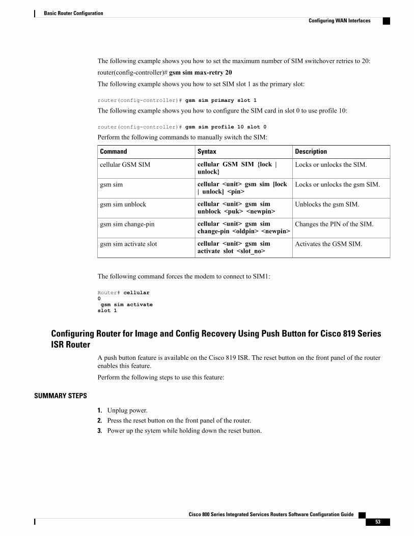
The following example shows you how to set the SIM switchover timeout period to 3 minutes:
router(config-controller)# gsm failovertimer 3
The following example shows you how to authenticate using an unencrypted pin:
Perform the following commands to manually switch the SIM:
DescriptionSyntaxCommand
Locks or unlocks the SIM.cellular GSM SIM {lock |unlock}
cellular GSM SIM
Locks or unlocks the gsm SIM.cellular <unit> gsm sim [lock| unlock] <pin>
gsm sim
Unblocks the gsm SIM.cellular <unit> gsm simunblock <puk> <newpin>
gsm sim unblock
Changes the PIN of the SIM.cellular <unit> gsm simchange-pin <oldpin> <newpin>
gsm sim change-pin
Activates the GSM SIM.cellular <unit> gsm simactivate slot <slot_no>
gsm sim activate slot
The following command forces the modem to connect to SIM1:
Router# cellular0gsm sim activateslot 1
Configuring Router for Image and Config Recovery Using Push Button for Cisco 819 SeriesISR Router
A push button feature is available on the Cisco 819 ISR. The reset button on the front panel of the routerenables this feature.
Perform the following steps to use this feature:
SUMMARY STEPS
1. Unplug power.2. Press the reset button on the front panel of the router.3. Power up the sytem while holding down the reset button.
Cisco 800 Series Integrated Services Routers Software Configuration Guide 53
Basic Router ConfigurationConfiguring WAN Interfaces
DETAILED STEPS
Step 1 Unplug power.Step 2 Press the reset button on the front panel of the router.Step 3 Power up the sytem while holding down the reset button.
The system LED blinks four times indicating that the router has accepted the button push.
What to Do Next
Using this button takes effect only during ROMMON initialization. During a warm reboot, pressing this buttonhas no impact on performance. Table 7: Push Button Functionality during ROMMON Initialization, on page54 shows the high level functionality when the button is pushed during ROMMON initialization.
Table 7: Push Button Functionality during ROMMON Initialization
IOS BehaviorROMMON Behavior
If the configuration named *.cfg is available in nvramstorage or flash storage, IOS will perform a backupof the original configuration and will boot up usingthis configuration.
You can only have one configuration filewith *.cfg option. Having more than one filewill result in uncertain operational behavior.
Note
• Boots using default baud rate.
• Performs auto-boot.
• Loads the *.default image if available oncompact flash
If no *.default image is available, theROMMONwill boot up with the first CiscoIOS image on flash.
Note
Examples of names for default images:
c800-universalk9-mz.SPA.default,
c-800-universalk9_npe-mz.151T.default,
image.default
You can only have one configuration filewith *.cfg option. Having more than one filewill result in uncertain operational behavior.
Note
Use the show platform command to display the current bootup mode for the router. The following sectionsshow sample outputs when the button is not pushed and when the button is pushed.
Output When Button Is Not Pushed: Example
router# show platform boot-recordPlatform Config Boot Record :============================Configuration Register at boot time : 0x0Reset Button Status at Boot Time : Not PressedStartup-config Backup Status at Boot: No StatusStartup-config(backup file)location : No Backup
Cisco 800 Series Integrated Services Routers Software Configuration Guide54
Basic Router ConfigurationConfiguring WAN Interfaces
Golden config file at location : No Recovery DetectedConfig Recovery Status : No Status
Output When Button Is Pushed: Example
router# show platform boot-record
Platform Config Boot Record :============================Configuration Register at boot time : 0x0Reset Button Status at Boot Time : PressedStartup-config Backup Status at Boot: OkStartup-config(backup file)location : flash:/startup.backup.19000716-225840-UTCGolden config file at location : flash:/golden.cfgConfig Recovery Status : Ok
Push Button in WLAN AP
When the push button on the front panel is pressed, WLAN AP will perform both image and configurationrecovery.
To perform image recovery, WLANwill go into the boot loader so that the user can download the image fromthe bootloader prompt.
To perform configuration recovery, WLAN AP will overwrite the contents of flash:/config.txtwith the contents of flash:/cpconfig-ap802.cfg file if available in flash drive. Otherwise,flash:/config.txt will be deleted.
Configuring WAN Mode on Cisco 860VAE ISRsThe Cisco 866VAE, Cisco 867VAE, Cisco 866VAE-K9, and Cisco 867VAE-K9 routers can be configuredto use either a GE interface or a DSL interface as a WAN link. DSL is the default WAN interface when theCisco 866VAE, Cisco 867VAE, Cisco 866VAE-K9, and Cisco 867VAE-K9 routers boot.
After the router boots up, the desired WAN interface can be selected using the wan mode command. WhenWAN mode is configured as Ethernet, both ATM0 and Ethernet0 interfaces will be forced into shutdownstate. Entering the no shutdown command on either of the DSL interfaces will be rejected with a messageWAN interface is Ethernet . Similarly, when the WAN mode is DSL, the GE WAN interface will be put inshutdown state and the no shutdown command will be rejected with the messageWAN interface is DSL .
The routers do not support enabling both GE and DSL interfaces simultaneously.Note
Use the wan mode dsl | ethernet command to switch from DSL to Ethernet interfaces or vice versa.
This section contains the following information:
Enabling WAN Mode
Perform the following steps to select and enable WAN mode.
Cisco 800 Series Integrated Services Routers Software Configuration Guide 55
Basic Router ConfigurationConfiguring WAN Interfaces
SUMMARY STEPS
1. enable2. show running-configuration3. wan mode {dsl | ethernet}4. exit
DETAILED STEPS
PurposeCommand or Action
Enables privileged EXEC mode.enableStep 1
Example:
Router> enable
• Enter your password if prompted.
Displays the default entries on boot up.show running-configurationStep 2
Example:
Router# show running-configuration
Selects the desired WAN mode.wan mode {dsl | ethernet}Step 3
Example:
Router(config)# wan mode dsl
Exits configuration mode and returns to it would take therouter back to privileged EXEC mode.
exit
Example:
Router(config)# exit
Step 4
Example:
Router#
Displaying WAN Mode Configuration
Use the show running-config command to view the initial configuration, as shown in the following examplefor a Cisco 866VAE router.
Your Cisco router displays the WAN mode during the boot sequence after the initial configuration iscomplete.
Cisco 800 Series Integrated Services Routers Software Configuration Guide56
Basic Router ConfigurationConfiguring WAN Interfaces
!! Last configuration change at 13:27:25 UTC Wed Feb 24 2010version 15.2no service padservice timestamps debug datetime msec localtime show-timezoneservice timestamps log datetime msec localtime show-timezoneno service password-encryption!hostname Router!boot-start-markerboot-end-marker!!enable password lab!no aaa new-modelwan mode ethernetno ipv6 cef!!!!!ip cef!crypto pki token default removal timeout 0!!!!!!controller VDSL 0shutdown!!!!!interface ATM0no ip addressshutdownno atm ilmi-keepalive!interface ATM0.1 point-to-pointip address 202.0.0.1 255.255.255.0pvc 0/202!!interface Ethernet0no ip addressshutdown!interface FastEthernet0no ip address!interface FastEthernet1no ip address!interface FastEthernet2no ip address!interface FastEthernet3no ip address!interface GigabitEthernet0ip address 1.0.0.1 255.255.255.0duplex autospeed auto!interface Vlan1no ip address
Cisco 800 Series Integrated Services Routers Software Configuration Guide 57
Basic Router ConfigurationConfiguring WAN Interfaces
!ip forward-protocol ndno ip http serverno ip http secure-server!!!!control-plane!!line con 0exec-timeout 0 0no modem enableline aux 0line vty 0 4logintransport input all!scheduler allocate 60000 1000!endRouter#
Configuring the Fast Ethernet LAN InterfacesThe Fast Ethernet LAN interfaces on your router are automatically configured as part of the default VLANand are not configured with individual addresses. Access is provided through the VLAN. You can also assignthe interfaces to other VLANs. For more information about creating VLANs, see Configuring EthernetSwitches
Configuring the Wireless LAN InterfaceThe Cisco 860, Cisco 880, and Cisco 890 series wireless routers have an integrated 802.11n module forwireless LAN connectivity. The router can then act as an access point in the local infrastructure. For moreinformation about configuring a wireless connection, see Chapter 11, “Basic Wireless Device Configuration.”
Configuring a Loopback InterfaceThe loopback interface acts as a placeholder for the static IP address and provides default routing information.
Perform these steps to configure a loopback interface, beginning in global configuration mode:
SUMMARY STEPS
1. interface loopback number2. ip address ip-address mask3. exit
DETAILED STEPS
PurposeCommand or Action
Enters configuration mode for the loopback interface.interface loopback numberStep 1
Cisco 800 Series Integrated Services Routers Software Configuration Guide58
Basic Router ConfigurationConfiguring the Fast Ethernet LAN Interfaces
Sets the IP address and subnet mask for the loopbackinterface.
ip address ip-address mask
Example:
Router(config-if)# ip address 10.108.1.1255.255.255.0
Step 2
Exits configuration mode for the loopback interface andreturns to global configuration mode.
exit
Example:
Router(config-if)# exit
Step 3
Example:
Router(config)#
Configuration Example: Configuring a Loopback InterfaceThe loopback interface in this sample configuration is used to support Network Address Translation (NAT)on the virtual-template interface. This configuration example shows the loopback interface configured on theFast Ethernet interface with an IP address of 200.200.100.1/24, which acts as a static IP address. The loopbackinterface points back to virtual-template1, which has a negotiated IP address.
!interface loopback 0ip address 200.200.100.1 255.255.255.0 (static IP address)ip nat outside!interface Virtual-Template1ip unnumbered loopback0no ip directed-broadcastip nat outside!
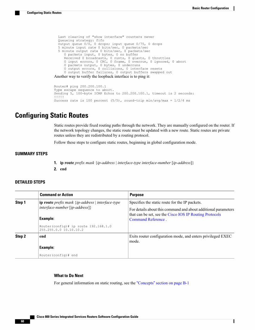
Verifying ConfigurationTo verify that you have properly configured the loopback interface, enter the show interface loopback command.You should see verification output similar to the following example.
Router# show interface loopback 0Loopback 0 is up, line protocol is upHardware is LoopbackInternet address is 200.200.100.1/24MTU 1514 bytes, BW 8000000 Kbit, DLY 5000 usec,
reliability 255/255, txload 1/255, rxload 1/255Encapsulation LOOPBACK, loopback not setLast input never, output never, output hang never
Cisco 800 Series Integrated Services Routers Software Configuration Guide 59
Basic Router ConfigurationConfiguring a Loopback Interface
Another way to verify the loopback interface is to ping it:
Router# ping 200.200.100.1Type escape sequence to abort.Sending 5, 100-byte ICMP Echos to 200.200.100.1, timeout is 2 seconds:!!!!!Success rate is 100 percent (5/5), round-trip min/avg/max = 1/2/4 ms
Configuring Static RoutesStatic routes provide fixed routing paths through the network. They are manually configured on the router. Ifthe network topology changes, the static route must be updated with a new route. Static routes are privateroutes unless they are redistributed by a routing protocol.
Follow these steps to configure static routes, beginning in global configuration mode.
SUMMARY STEPS
1. ip route prefix mask {ip-address | interface-type interface-number [ip-address]}2. end
DETAILED STEPS
PurposeCommand or Action
Specifies the static route for the IP packets.ip route prefix mask {ip-address | interface-typeinterface-number [ip-address]}
Step 1
For details about this command and about additional parametersthat can be set, see the Cisco IOS IP Routing ProtocolsCommand Reference .Example:
Router(config)# ip route 192.168.1.0255.255.0.0 10.10.10.2
Exits router configuration mode, and enters privileged EXECmode.
end
Example:
Router(config)# end
Step 2
What to Do Next
For general information on static routing, see the “Concepts” section on page B-1
Cisco 800 Series Integrated Services Routers Software Configuration Guide60
ExampleIn the following configuration example, the static route sends out all IP packets with a destination IP addressof 192.168.1.0 and a subnet mask of 255.255.255.0 on the Fast Ethernet interface to another device with anIP address of 10.10.10.2. Specifically, the packets are sent to the configured PVC.
You do not need to enter the command marked “(default).” This command appears automatically in theconfiguration file generated when you use the show running-config command.
Verifying Static Routing ConfigurationTo verify that you have properly configured static routing, enter the show ip route command and look forstatic routes signified by the “S.”You should see verification output similar to the following:
Router# show ip routeCodes: C - connected, S - static, R - RIP, M - mobile, B - BGP
D - EIGRP, EX - EIGRP external, O - OSPF, IA - OSPF inter areaN1 - OSPF NSSA external type 1, N2 - OSPF NSSA external type 2E1 - OSPF external type 1, E2 - OSPF external type 2i - IS-IS, su - IS-IS summary, L1 - IS-IS level-1, L2 - IS-IS level-2ia - IS-IS inter area, * - candidate default, U - per-user static routeo - ODR, P - periodic downloaded static route
Gateway of last resort is not set10.0.0.0/24 is subnetted, 1 subnets
C 10.108.1.0 is directly connected, Loopback0S* 0.0.0.0/0 is directly connected, FastEthernet0
Configuring Dynamic RoutesIn dynamic routing, the network protocol adjusts the path automatically, based on network traffic or topology.Changes in dynamic routes are shared with other routers in the network.
The Cisco routers can use IP routing protocols, such as Routing Information Protocol (RIP) or EnhancedInterior Gateway Routing Protocol (EIGRP), to learn routes dynamically. You can configure either of theserouting protocols on your router.
Configuring Routing Information ProtocolTo configure the RIP routing protocol on the router, perform these steps, beginning in global configurationmode:
Cisco 800 Series Integrated Services Routers Software Configuration Guide 61
Example Configuration: Configuring Dynamic Routing Protocol
The following configuration example shows RIP version 2 enabled in IP network 10.0.0.0 and 192.168.1.0.
To see this configuration, use the show running-config command from privileged EXEC mode.
!Router# show running-configrouter ripversion 2network 10.0.0.0network 192.168.1.0no auto-summary!
Verifying RIP Configuration
To verify that you have properly configured RIP, enter the show ip route command and look for RIP routessignified by “R.” You should see a verification output like the following example.
Router# show ip routeCodes: C - connected, S - static, R - RIP, M - mobile, B - BGP
D - EIGRP, EX - EIGRP external, O - OSPF, IA - OSPF inter areaN1 - OSPF NSSA external type 1, N2 - OSPF NSSA external type 2E1 - OSPF external type 1, E2 - OSPF external type 2i - IS-IS, su - IS-IS summary, L1 - IS-IS level-1, L2 - IS-IS level-2ia - IS-IS inter area, * - candidate default, U - per-user static routeo - ODR, P - periodic downloaded static route
Gateway of last resort is not set10.0.0.0/24 is subnetted, 1 subnets
C 10.108.1.0 is directly connected, Loopback0R 3.0.0.0/8 [120/1] via 2.2.2.1, 00:00:02, Ethernet0/0
Configuring Enhanced Interior Gateway Routing ProtocolTo configure Enhanced Interior Gateway Routing Protocol (EIGRP), perform these steps, beginning in globalconfiguration mode:
SUMMARY STEPS
1. router eigrp as-number2. network ip-address3. end
DETAILED STEPS
PurposeCommand or Action
Enters router configuration mode and enables EIGRP on therouter. The autonomous-system number identifies the route toother EIGRP routers and is used to tag the EIGRP information.
router eigrp as-number
Example:
Step 1
Cisco 800 Series Integrated Services Routers Software Configuration Guide 63
Specifies a list of networks on which EIGRP is to be applied,using the IP address of the network of directly connectednetworks.
network ip-address
Example:
Step 2
Example:
Router(config)# network 192.145.1.0
Example:
Router(config)# network 10.10.12.115
Exits router configuration mode and enters privileged EXECmode.
end
Example:
Step 3
Example:
Router(config-router)# end
Example:
Router#
What to Do Next
For general information on EIGRP concepts, see the “Enhanced IGRP” section on page B-3
Example Configuration: EIGRP
The following configuration example shows the EIGRP routing protocol enabled in IP networks 192.145.1.0and 10.10.12.115. The EIGRP autonomous system number is 109.
To see this configuration, use the show running-config command, beginning in privileged EXEC mode.
To verify that you have properly configured IP EIGRP, enter the show ip route command and look for EIGRProutes indicated by “D.” You should see verification output similar to the following:
Router# show ip routeCodes: C - connected, S - static, R - RIP, M - mobile, B - BGP
D - EIGRP, EX - EIGRP external, O - OSPF, IA - OSPF inter areaN1 - OSPF NSSA external type 1, N2 - OSPF NSSA external type 2E1 - OSPF external type 1, E2 - OSPF external type 2i - IS-IS, su - IS-IS summary, L1 - IS-IS level-1, L2 - IS-IS level-2ia - IS-IS inter area, * - candidate default, U - per-user static routeo - ODR, P - periodic downloaded static route
Gateway of last resort is not set10.0.0.0/24 is subnetted, 1 subnets
C 10.108.1.0 is directly connected, Loopback0D 3.0.0.0/8 [90/409600] via 2.2.2.1, 00:00:02, Ethernet0/0
Cisco 800 Series Integrated Services Routers Software Configuration Guide 65