1 CLICK CLICK CLICK Classification Standard type Low current load type Actuators Pin plunger Short plunger Panel mount plunger Panel mount roller plunger/ cross roller plunger Fine plunger Lever Roller lever Short roller lever One-way roller lever Reverse action lever Reverse action roller lever Reverse action short roller lever SELECTION GUIDE Basic Switches BZSeries These switches have been used extensively and have earned the high respect of our customers. Standard basic switches BZ Series are representative of Yamatake basic switches for their range of models and high performance.
Transcript
1
CLICKCLICKCLICK
ClassificationStandard type Low current load type
Actuators
Pin plunger
Short plunger
Panel mount plunger
Panel mount roller plunger/cross roller plunger
Fine plunger
Lever
Roller lever
Short roller lever
One-way roller lever
Reverse action lever
Reverse action roller lever
Reverse action short roller lever
SELECTION GUIDE
Basic Switches
BZSeries
These switches have been used extensively and have earned the high respect of our customers. Standard basic switches BZ Series are representative of Yamatake basic switches for their range of models and high performance.
High-quality switches with UL/CSA certification.*UL approval number: E37559. CSA: LR61643
Wide range of types
Standard type
Reverse action lever type (effective when there is impact operation)
A wide range of actuators is available. Select the actuator according to your
specific requirements and conditions of use.
Mechanical life: 20 million cycles (pin plunger type)
EN 60947-5-1 (IEC 947-5-1) and CCC compliant types are available.
APPLICATIONSMachine tools and various industrial machineryControl of pressure, temperature, fluid level, weight, speed and timeHousehold equipment, automobiles and control equipment
Standard type
4
External Dimensions
Circuit configuration Terminal dimensions
Screw terminal
BZ-2R-T4-J BZ-2RD-T4-J
Model Switch mountingscrew
BZ-2R
Single-pole double-throw(SPDT)
Note: On reverse action types, the N.O. and N.C. terminal positions are reversed.
—
—
—
—
Reverse actionlever
Reverse action shortroller lever
One-wayroller lever
Reverse actionroller lever
Max. 1.57
Max. 1.67
Min. 1.67
Min. 0.56
Min. 0.27
Min. 0.42
Max. 2.35
Max. 5.30
43.3±0.4 41.3±0.4
19.1±0.8
30.2±0.8
30.2±0.531.5±0.5
25±1.2
35±1
Min. 2
Min. 4
Min. 5.6
Min. 2.4
0.08
to
0.51
0.1
to
0.9
0.05
to
0.7
0.03
to
0.3
UL/CSA
UL/CSA
U/CSA
UL/CSA
M4 screw
M4 screw
M4 screw
M4 screw
BZ-2RW826-T4-J
BZ-2RM-T4-J
BZ-2RM2-T4-J
BZ-2RM22-T4-J
M4 screw
General tolerance: 0.4mm
unit: mm
Actuators
Property
Standardscertification
Catalog listingTerminalO.F.(N)
Operating force
F.P.(mm)
Free position
P.T.(mm)
Pretravel
O.P.(mm)
Operating position
O.T.(mm)
Overtravel
M.D.(mm)
Movement differential
R.F.(N)
Release force
Circuit configuration and terminal diagrams
5
BZ-2RQ1-T4-J BZ-2RQ18-T4-J
BZ-2RQ181-T4-J BZ-2RS-T4-J
BZ-2RW80-T4-J BZ-2RW82-T4-J
BZ-2RW826-T4-JBZ-2RW822-T4-J
General tolerance: 0.4mm
unit: mm
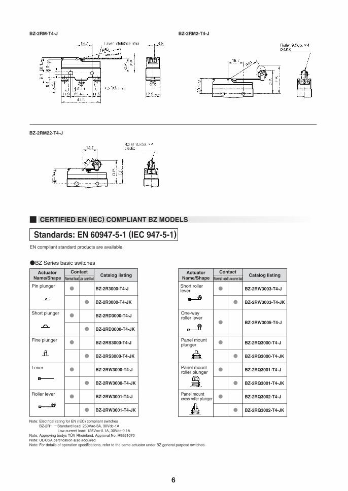
6
BZ-2RM2-T4-JBZ-2RM-T4-J
BZ-2RM22-T4-J
CERTIFIED EN (IEC) COMPLIANT BZ MODELS
Standards: EN 60947-5-1 (IEC 947-5-1)
Short rollerlever
One-wayroller lever
Panel mountplunger
Panel mountroller plunger
Panel mountcross roller plunger
BZ-2RW3003-T4-J
BZ-2RW3003-T4-JK
BZ-2RW3005-T4-J
BZ-2RQ3000-T4-J
BZ-2RQ3000-T4-JK
BZ-2RQ3001-T4-J
BZ-2RQ3001-T4-JK
BZ-2RQ3002-T4-J
BZ-2RQ3002-T4-JK
EN compliant standard products are available.
Catalog listingNormal load Low current load
Pin plunger
Short plunger
Fine plunger
Lever
Roller lever
BZ-2R3000-T4-J
BZ-2R3000-T4-JK
BZ-2RD3000-T4-J
BZ-2RD3000-T4-JK
BZ-2RS3000-T4-J
BZ-2RS3000-T4-JK
BZ-2RW3000-T4-J
BZ-2RW3000-T4-JK
BZ-2RW3001-T4-J
BZ-2RW3001-T4-JK
ActuatorName/Shape
ContactCatalog listing
Normal load Low current loadActuator
Name/ShapeContact
BZ Series basic switches
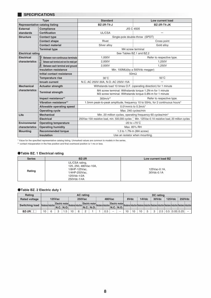
Note: Electrical rating for EN (IEC) compliant switches BZ-2R······Standard load: 250Vac-3A, 30Vdc-1A Low current load: 125Vac-0.1A, 30Vdc-0.1A
Note: Approving bodys TÜV Rheinland, Approval No. R9551070Note: UL/CSA certification also acquiredNote: For details of operation specifications, refer to the same actuator under BZ general purpose switches.
7
Note: CCC compliant model also available
250Vac or 30Vdc
125Vac or 30Vdc
AC-15 3A-250Vac, DC-12 1A-30Vdc
AC-12 0.1A-125Vac, DC-12 0.1A-30Vdc
45 to 65Hz or “d.c.”
250Vac
4,000V
15A
1A
Instant blowing fuse 15A, ABC 15(15A) made by Bussmann or equivalent
1000A
-,L,M,N,W,S,Q: Category III D,B: Class II
N.A.
Standard loadLow current loadStandard loadLow current load