126


WHAT IS MACHINE LANGUAGE?
At the heart of every microcomputer, is a central microprocessor. It'sa very special microchip which is the "brain" of the computer. TheCommodore 64 is no exception. Every microprocessor understands itsown language of instructions. These instructions are called machine lan-guage instructions. To put it more precisely, machine language is theONLY programming language that your Commodore 64 understands. Itis the NATIVElanguage of the machine.
If machine language is the only language that the Commodore 64understands, then how does it understand the CBM BASIC programminglanguage? CBM BASIC is NOT the machine language of the Commodore64. What, then, makes the Commodore 64 understand CBM BASIC in-structions like PRINT and GOTO?
To answer this question, you must first see what happens inside yourCommodore 64. Apart from the microprocessor which is the brain of theCommodore 64, there is a machine language program which is stored ina special type of memory so that it can't be changed. And, more impor-tantly, it does not disappear when the Commodore 64 is turned off,
unlike a program that you may have written. This machine languageprogram is called the OPERATING SYSTEMof the Commodore 64. YourCommodore 64 knows what to do when it's turned on because itsOPERATING SYSTEM(program) is automatically "RUN."
210 BASIC TO MACHINE LANGUAGE

The OPERATING SYSTEM is in charge of "organizing" all the memory
in your machine for various tasks. It also looks at what characters youtype on the keyboard and puts them onto the screen, plus a whole
number of other functions. The OPERATING SYSTEM can be thought of
as the "intelligence and personality" of the Commodore 64 (or any com-puter for that matter). So when you turn on your Commodore 64, the
OPERATING SYSTEM takes control of your machine, and after it hasdone its housework, it then says:
READY..
The OPERATING SYSTEM of the Commodore 64 then allows you to
type on the keyboard, and use the built-in SCREEN EDITOR on the Com-modore 64. The SCREEN EDITOR allows you to move the cursor, DELete,INSert, etc., and is, in fact, only one part of the operating system that is
built in for your convenience.All of the commands that are available in CBM BASIC are simply
recognized by another huge machine language program built into your
Commodore 64. This huge program "RUNs" the appropriate piece ofmachine language depending on which CBM BASIC command is being
executed. This program is called the BASIC INTERPRETER, because it
interprets each command, one by one, unless it encounters a commandit does not understand, and then the familiar message appears:
?SYNTAX ERROR
READY..WHAT DOES MACHINE CODE LOOK LIKE?
You should be familiar with the PEEKand POKE commands in the CBM
BASIC language for changing memory locations. You've probably used
them for graphics on the screen, and for sound effects. Each memorylocation has its own number which identifies it. This number is known as
the "address" of a memory location. If you imagine the memory in theCommodore 64 as a street of buildings, then the number on each door
is, of course, the address. Now let's look at which parts of the street areused for what purposes.
BASIC TO MACHINE LANGUAGE 211
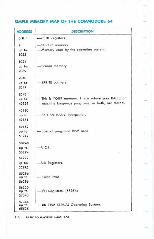
SIMPLE MEMORY MAP OF THE COMMODORE64
212 BASIC TO MACHINE LANGUAGE
ADDRESS DESCRIPTION
0& 1 -6510 Registers.
2 -Start of memory.up to: -Memory used by the operating system.1023
1024
up to: -Screen memory.2039
2040
up to: -SPRITE pointers.2047
2048
up to: - This is YOUR memory. This is where your BASIC or40959 machine language programs, or both, are stored.
40960
up to: -8K CBM BASIC Interpreter.49151
49152
up to: -Special programs RAM area.53247
53248
up to: -VIC-II.53294
54272
up to: -SID Registers.55295
55296up to: -Color RAM.56296
56320up to: -110 Registers. (6526's)57343
57344up to: -8K CBM KERNALOperating System.65535

If you don't understand what the description of each part of memorymeans right now, this will become clear from other parts of this manual.
Machine language programs consist of instructions which mayor maynot have operands (parameters) associated with them. Each instructiontakes up one memory location, and any operand is contained in one or.two locations following the .instruction.
In your BASIC programs, words like PRINTand GOTO do, in fact, onlytake up one memory location, rather than one for each character of theword. The contents of the location that represents a particular BASICkeyword is called a token. In machine language, there are differenttokens for different instructions, which also take up just one byte (mem-ory location =byte).
Machine language instructions are very simple. Therefore, each indi-vidual instruction cannot achieve a great deal. Machine language in-structions either change the contents of a memory location, or changeone of the internal registers (special storage locations) inside .the micro-processor. The internal registers form the very basis of machine lan-guage.
THE REGISTERS INSIDE THE6510 MICROPROCESSOR
THE ACCUMULATOR
This is THE most important register in the microprocessor. Various ma-
chine language instructions allow you to copy the c;:ontents of a memorylocation into.the accumulator, copy the contents of the accumulator intoa memory location, modify the contents of the accumulator or someother register directly, without affecting any memory. And the ac-cumulator is the only register that has instructions for performing math.
THE X INDEX REGISTER
This is a very important register. There are instructions for nearly all ofthe transformations you can make to the accumulator. But there areother instructions for things that only the X register can do. Various ma-chine language instructions allow you to copy the contents of a memorylocation into the X register,copy the contents of the X register into amemory location, and modify the contents of the X, or some other regis-ter directly.
BASIC TO MACHINE LANGUAGE 213

THE Y INDEX REGISTER
This is a very important register. There are instructions for nearly all of
the transformations you can make to the accumulator, and the X regis-
ter. But there are other instructions for things that only the Y register cando. Various machine language instructions allow you to copy the con-
tents of a memory location into the Y register, copy the contents of the Yregister into a memory location, and modify the contents of the Y, or
some other register directly.
THE STATUS REGISTER
This register consists of eight "flags" (a flag = something that indi-cates whether something has, or has not occurred).
THE PROGRAM COUNTER
This contains the address of the current machine language instruction
being executed. Since the operating system is always "RUN"ning in the
Commodore 64 (or, for that matter, any computer), the program counteris always changing. It could only be stopped by halting the microproces-sor in some way.
THE STACK POINTER
This register contains the location of the first empty place on the stack.
The stack is used for temporary storage by machine language pro-grams, and by the computer.
THE INPUT/OUTPUTPORT
This register appears at memory locations 0 (for the DATADIRECTION
REGISTER)and 1 (for the actual PORT). It is an 8-bit input/output port.On the Commodore 64 this register is used for memory management, to
allow the chip to control more than 64K of RAM and ROM memory.
The details of these registers are not given here. They are explained
as the principles needed to explain them are' explained.
HOW DO YOU WRITE MACHINE LAN-GUAGE PROGRAMS?
Since machine language programs reside in memory, and there is nofacility in your Commodore 64 for writing and editing machine language
214 BASIC TO MACHINE. LANGUAGE

programs, you must use either a program to do this, or write for yourselfa BASIC program that "allows" you to write mClchine language.
The most common methods used to write machine language pro-grams are assembler progams. These packages allow you to write ma-chine language instructions in a standardized mnemonic format, whichmakes the machine language program a lot more readable than astream of numbers! Let's review: A program that allows you to writemachine language programs in mnemonic format is called an assem-bler. Incidentally, a program that displays a machine language pro-gram in mnemonic format is called a disassembler. Available for yourCommodore 64 is a machine language monitor cartridge (with assem-bler/ disassembler, etc.) made by Commodore:
64MON
The 64MON cartridge available from your local dealer, is a programthat allows you to escape from the world of CBM BASIC, into the land ofmachine language. It can display the contents of the internal registers inthe 6510 microprocessor, and it allows you to display portions of mem-ory, and change them on the screen, using the screen editor. It also hasa built-in assembler and disassembler, as well as many other featuresthat allow you to write and edit machine language programs easily. Youdon't HAVEto use an assembler to write machine language, but the taskis considerably easier with it. If you wish to write machine languageprograms, it is strongly suggested that you purchase an assembler ofsome sort. Without an assembler you will probably have to "POKE" themachine language program into memory, which is totally unadvisable.This manual will give its examples in the format that 64MON uses, fromnow on. Nearly all assembler formats ar~ the same, therefore the ma-chine language examples shown will almost certainly be compatible.with any assembler. But before explaining any of the other features of64MON, the hexadecimal numbering system must be explained.
HEXADECIMAL NOTATION
Hexadecimal notation is used by most machine language program-
mers when they talk about a number or address in a machine languageprogram.
Some assemblers let you refer to addresses and numbers in decimal(base 10), binary (base 2), or even octal (base 8) as well as hexadeci-
BASICTO MACHINELANGUAGE 215

. I
mal (base 16) (or just "hex" as most people say). These assemblers dothe conversions for you.
Hexadecimal probably seems a little hard to grasp at first, but likemost things, it won't take long to master with practice.
By looking at decimal (base 10) numbers, you can see that each digitfalls somewhere in the range between zero and a number equal to thebase less one (e.g., 9). THIS IS TRUEOF ALL NUMBER BASES.Binary(base 2) numbers have digits ranging from zero to one (which is one lessthan the base). Similarly, hexadecimal numbers should have digits rang-ing from zero to fifteen, but we do not have any single digit figures forthe numbers ten to fifteen, so the first six letters of the alphabet areused instead:
216 BASIC TO MACHINE LANGUAGE
DECIMAL HEXADECIMAL BINARY
0 0 000000001 1 000000012 2 000000103 3 000000114 4 000001005 5 000001016 6 000001107 7 000001118 8 000010009 9 00001001
10 A 0000101011 B 0000101112 C 0000110013 D 0000110114 E 0000111015 F 0000111116 10 00010000

let's look at it another way; here's an example of how a base 10(decimal number) is constructed:
Base raised byincreasing powers:
Equals: .1000 100 10
Consider 4569 (base 10) 4 5 6 9=(4x 1000)+(5X 100)+(6X 10)+9
Now look at an example of how a base 16 (hexadecimal number) isconstructed:
Base raised byincreasing powers:
Equals: .4096 256 16
Consider 11D9 (base 16) lID 9=1 X4096+1 X256+13X 16+9
Therefore, 4569 (base 10) = 11 D9 (base 16)
The range for addressable memory locations is 0-65535 (as wasstated earlier). This range is therefore o-FFFF in hexadecimal notation.
Usually hexadecimal numbers are prefixed with a dollar sign ($). Thisis to distinguish them from decimal numbers. let's look at some "hex"numbers, using 64MON, by displaying the contents of some memory bytyping:
SYS 8*4096 (or SYS 12*4096)B*
PC SR AC XRYR SP
.; 0401 32 04 5E 00 F6 (these may be different)
Then if you type in:
.M 0000 0020 (and press 8:1:1111:11.).
you will see rows of 9 hex numbers. The first 4-digit number is the ad-dress of the first byte of memory being shown in that row, and the other
eight numbers are the actual contents of the memory locations begin-ning at that start address.
You should really try to learn to "think" in hexadecimal. It's not toodifficult, because you don't have to think about converting it back into
BASIC TO MACHINE LANGUAGE 217

decimal. For example, if you said that a particular value is stored at$14ED instead of 5357, it shouldn't make any difference.
YOUR FIRST MACHINE LANGUAGE INSTRUCTION
LDA- LOADTHEACCUMULATOR
In 6510 assembly language, mnemonics are always three characters.LDA represents "load accumulator with . . . ," and what the ac-
cumulator should be loaded with is decided by the parameter(s) asso-ciated with that instruction. The assembler knows which token is repre-sented by each mnemonic, and when it "assembles" an instruction, itsimply puts into memory (at whatever address has been specified), thetoken, and what parameters, are given. Some assemblers give errormessages, or warnings when you try to assemble something that eitherthe assembler, or the 6510 microprocessor, cannot do.
If you put a "#" symbol in front of the parameter associated with theinstruction, this means that you want the register specified in the instruc-tion to be loaded with the "value" after the "#." For example:
LDA #$05 ~This instruction will put $05 (decimal 5) into the accumulator register.The assembler will put into the specified address for this instruction, $A9(which is the token for this particular instruction, in this mode), and it willput $05 into the next location after the location containing the instruction($A9).
If the parameter to be used by an instruction has "#" before it; i.e.,the parameter is a "value," rather than the contents of a memory loca-tion, or another register, the instruction is said to be in the "immediate"mode. To put this into perspective, let's compare this with anothermode:
If you want to put the contents of memory location $102E into theaccumulator, you're using the "absolute" mode of instruction:
LDA $102E
The assembler can distinguish between the two different modes becausethe latter does not have a "#" before the parameter. The 6510 micro-processor can distinguish between the immediate mode, and the abso-lute mode of the LDA instruction, because they have slightly differenttokens. LDA (immediate) has $A9 as its token, and LDA(absolute), has$AD as its token.
218 BASICTO MACHINELANGUAGE
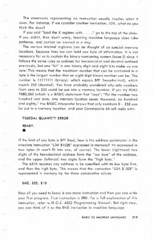
The mnemonic representing an instruction usually implies what itdoes. For instance, if we consider another instruction, LDX, what do youthink this does?
If you said "load the X register with. . . ," go to the top of the class.If you didn't, then don't worry, learning machine language does takepatience, and cannot be learned in a day.
The various internal registers can be thought of as special memorylocations, because they too can hold one byte of information. It is notnecessary for us to explain the binary numbering system (base 2) since itfollows the same rules as outlined for hexadecimal and decimal outlined
previously, but one "bit" is one binary digit and eight bits make up onebyte! This means that the maximum number that can be contained in a
byte is the largest number that an eight digit binary number can be. Thisnumber is 11111111 (binary), which equals $FF (hexadecimal), whichequals 255 (decimal). You have probably wondered why only numbersfrom zero to 255 could be put into a memory location. If you try POKE7680,260 (which is a BASIC statement that "says": "Put the number twohundred and sixty, into memory location seven thousand, six hundred
and eighty," the BASIC interpreter knows that only numbers 0 - 255 canbe put in a memory location, and your Commodore 64 will reply with:
?ILLEGAL QUANTITY ERROR
READY..
If the limit of one byte is $FF (hex), how is the address parameter in theabsolute instruction "LDA $102E" expressed in memory? It's expressed intwo bytes (it won't fit into one, of course). The lower (rightmost) twodigits of the hexadecimal address form the "low byte" of the address,and the upper (leftmost) two digits form the "high byte."
The 6510 requires any address to be specified with its low byte first,and then the high byte. This means that the instruction "lDA $102E" isrepresented in memory by the three consecutive values:
$AD, $2E, $10
Now all you need to know is one more instruction and then you can writeyour first program. That instruction is BRK. For a full explanation of thisinstruction, refer to M.O.S. 6502 Programming Monuol. But right now,you can think of it as the END instruction in machine language.
BASIC TO MACHINE LANGUAGE 219

If we write a program with 64MON and put the BRKinstruction at theend, then when the program is executed, it will return to 64MON when it
is finished. This might not happen if there is a mistake in your program,or the BRK instruction is never reached (just like an END statement inBASIC may never get executed). This means that if the Commodore 64
didn't have a STOP key, you wouldn't be able to abort your BASIC pro-grams!
WRITING YOUR FIRST PROGRAM
If you've used the POKEstatement in BASIC to put characters onto thescreen, you're aware that the character codes for POKEing are differentfrom CBM ASCII character values. For example, if you enter:
PRINT ASq"A") (and press .:~llIm~/. )
the Commodore 64 will respond with:
65
READY..
However, to put an "A" onto the screen by POKEing, the code is I,enter:
POKE 1024,1 :POKE 55296,14 (and .WII":~/. ) (1024 is the start
of screen memory)
The "P" in the POKE statement should now be an "A."
Now let's try this in machine language. Type the following in 64MON:(Your cursor should be flashing alongside a "." right now.)
.A 1400 LDA#$01 (and press .WIII':U.
220 BASIC TO MACHINE LANGUAGE
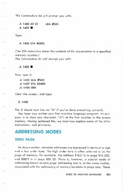
The Commodore 64 will prompt you with:
.A 1400 A9 01
.A 1402. LDA #$01
Type:
.A 1402 STA $0400
(The STA instruction stores the contents of the accumulator in a specified'memory location.)The Commodore 64 will prompt you with:
.A 1405 ..
Now type in:
.A 1405 LDA #$OE
.A 1407 STA $D800
.A 140A BRK
Clear the screen', and type:
G 1400
The G should turn into an "A" if you've done everything correctly.You have now written your first machine language program. Its pur-
pose is to store one character ("A") at the first location in the screenmemory. Having achieved this, we must now explore some of the otherinstructions, and principles.
ADDRESSING MODES
ZERO PAGE
As shown earlier, absolute addresses are expressed in terms of a highand a low order byte. The high order byte is often referred to as the
page of memory. For example, the address $1637 is in page $16 (22),and $0277 is in page $02 (2). There is, however, a special mode ofaddressing known as zero page addressing and is, as the name implies,associated with the addressing of memory locations in page zero. These
BASIC TO MACHINE LANGUAGE 221
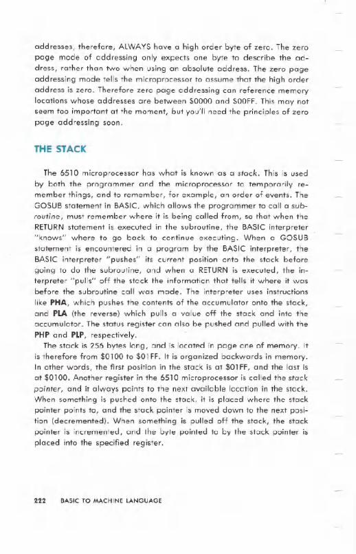
addresses, therefore, ALWAYShave a high order byte of zero. The zeropage mode of addressing only expects one byte to describe the ad-dress, rather than two when using an absolute address. The zero pageaddressing mode tells the microprocessor to assume that the high orderaddress is zero. Therefore zero page addressing can reference memorylocations whose addresses are between $0000 and $OOFF.This may notseem too important at the moment, but you'll need the principles of zeropage addressing soon.
THE STACK
The 6510 microprocessor has what is known as a stack. This is usedby both the programmer and the microprocessor to temporarily re-member things, and to remember, for example, an order of events. TheGOSUB statement in BASIC, which allows the programmer to call a sub-routine, must remember where it is being called from, so that when theRETURNstatement is executed in the subroutine, the BASIC interpreter"knows" where to go back to continue executing. When a GOSUBstatement is encountered in a program by the BASIC interpreter, theBASIC interpreter "pushes" its current position onto the stack beforegoing to do the subroutine, and when a RETURNis executed, the in-terpreter "pulls" off the stack the information that tells it where it wasbefore the subroutine call was made. The interpreter uses instructionslike PHA, which pushes the contents of the accumulator onto the stack,and PLA (the reverse) which pulls a value off the stack and into theaccumulator. The status register can also be pushed and pulled with thePHP and PLP, respectively.
The stack is 256 bytes long, and is located in page one of memory. Itis therefore from $0100 to $01 FF. It is organized backwards in memory.In other words, the first position in the stack is at $01 FF, and the last isat $0100. Another register in the 6510 microprocessor is called the stack
pointer, and it always points to the next available location in the stack.When something is pushed onto the stack, it is placed where the stackpointer points to, and the stack pointer is moved down to the next posi~tion (decremented). When something is pulled off the stack, the stackpointer is incremented, and the byte pointed to by the stack pointer is
placed into the specified register.
222 BASIC TO MACHINE LANGUAGE
Up to this point, we have covered immediate, zero page, and abso-lute mode instructions. We have also covered, but have not really talkedabout, the "implied" mode. The implied mode means that information is
implied by an instruction itself. In other words, what registers, flags,and memory the instruction is referring to. The examples we have seenare PHA, PLA, PHP, and PLP, which refer to stack processing and. theaccumulator and status registers, respectively.
NOTE: The X register will be referred to as X from now on, and similarly A (ac-cumulator), Y (Y index registe~), 5 (stack pointer), and P (processor status).
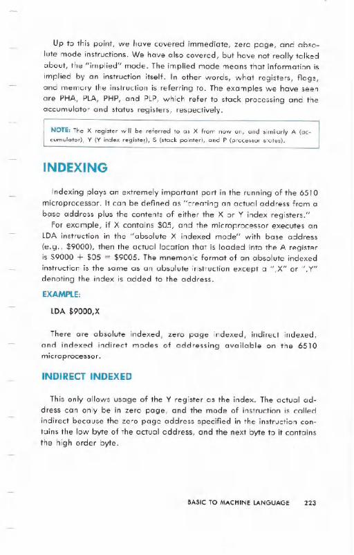
INDEXING
Indexing plays an extremely important part in the running of the 6510microprocessor. It can be defined as "creating an actual address from abase address plus the contents of either the X or Y index registers."
For example, if X contains $05, and the microprocessor executes anLDA instruction in the "absolute X indexed mode" with base address
(e.g., $9000), then the actual location that is loaded into the A registeris $9000 + $05 = $9005. The mnemonic format of an absolute indexedinstruction is the same as an absolute instruction except a ",X" or ", Y"denoting the index is added to the address.
EXAMPLE:
LDA $9000,X
There are absolute indexed, zero page indexed, indirect indexed,and indexed indirect modes of addressing available on the 6510microprocessor.
INDIRECT INDEXED
This only allows usage of the Y register as the index. The actual ad-dress can only be in zero page, and the mode of instruction is calledindirect because the zero page address specified in the instruction con-tains the low byte of the actual address, and the next byte to it containsthe high order byte.
BASICTO MACHINELANGUAGE 223

EXAMPLE:
Let us suppose that location $02 contains $45, and location $03 con-tains $1 E. If the instruction to load the accumulator in the indirect inde-
xed mode is executed and the specified zero page address is $02, thenthe actual address will be:
Low order = contents of $02
High order = contents of $03Y register =$00
Thus the actual address = $1E45 + Y = $1E45.
The title of this mode does in fact imply an indirect principle, althoughthis maybe difficult to grasp at first sight. Let's look at it another way:
"I am going to deliver this letter to the post office at address$02,MEMORY ST., and the address on the letter is $05 houses past$1600, MEMORY street." This is equivalent to the code:
LDA #$00STA $02LDA #$16STA $03LDY#$05LDA ($02), Y
- load low order actual .base address
- set the low byte .of the indirect address- load high order indirect address- set the high byte of the indirect address- set the indirect index (Y)
- load indirectly indexed by Y
INDEXED INDIRECT
Indexed indirect only allows usage of the X register as the index. Thisis the same as indirect indexed, except it is the zero page address of thepointer that is indexed, rather than the actual base address. Therefore,the actual base address IS the actual address because the index has
already been used for the indirect. Index indirect would also be used if
224 BASIC TO MACHINE LANGUAGE

a table of indirect pointers were located in zero page memory, and theX register could then specify which indirect pointer to use.
EXAMPLE:
Let us suppose that location $02 contains $45, and location $03 con-tains $10. If the instruction to load the accumulator in the indexed indi-
rect mode is executed and the specified zero page address is $02, thenthe actual address will be:
Low order = contents of ($02 + X)High order = contents of ($03+X)X register = $00
Thus the actual pointer is in = $02 + X = $02.
Therefore, the actual address is the indirect address contained in $02which is again $1045.
The title of this mode does in fact imply the principle, although it maybe difficult to grasp at first sight. Look at it this way:
"I am going to deliver this letter to the fourth post office at address$01 ,MEMORY ST., and the address on the letter will then be delivered to$1600, MEMORY street." This is equivalent to the code:
LDA #$00STA $06LDA #$16STA $07LDX#$05
LDA ($02,X)
- load low order actual base address
- set the low byte of the indirect address- load high order indirect address- set the high byte of the indirect address- set the indirect index (X)-load indirectly indexed by X
NOTE: Of the two indirect methods of addressing, the first (indirect indexed) is far
more widely used.
BASIC TO MACHINE LANGUAGE 225

BRANCHES AND TESTING
Another very important principle in machine language is the ability totest, and detect certain conditions, in a smiliar fashion to the "IF. . .THEN, IF . . . GOTO" structure in CBM BASIC.
The various flags in the status register are affected by different in-structions in different ways. For example, there is a flag that is set whenan instruction has caused a zero result, and is reset when a result is notzero. The instruction:
LDA #$00
will cause the zero result flag to be set, because the instruction has
resulted in the .accumulator containing a zero.There are a set of instructions that will, given a particular condition,
branch to another part of the program. An example of a branch instruc-tion is BEQ, which means Branch if result EQual to zero. The branchinstructions branch if the condition is true, and if not, the program con-tinues onto the next instruction, as if nothing had occurred. The branchinstructions branch not by the result of the previous instruction(s), but byinternally examining the status register. As was just mentioned, there isa zero result flag in the status register. The BEQ instruction branches ifthe zero result flag (known as Z) is set. Every branch instruction has anopposite branch instruction. The BEQ instruction has an opposite instruc-tion BNE, which means Branch on result Not Equal to zero (i.e., Z notset).
The index registers have a number of associated instructions whichmodify their contents. For example, the INX instruction INcrements the Xindex register. If the X.register contained $FF before it was incremented(the maximum number the X register can contain), it will "wrap around"back to zero. If you wanted a program to continue to do something untilyou had performed the increment of the X index that pushed it aroundto zero, you could use the BNE instruction to continue "looping" around,until X became zero.
The reverse of INX, is DEX,which is DEcrement the X index register. Ifthe X index register is zero, DEX wraps around to $FF. Similarly, thereare INY and DEYfor the Y index register.
226 BASIC TO MACHINE LANGUAGE
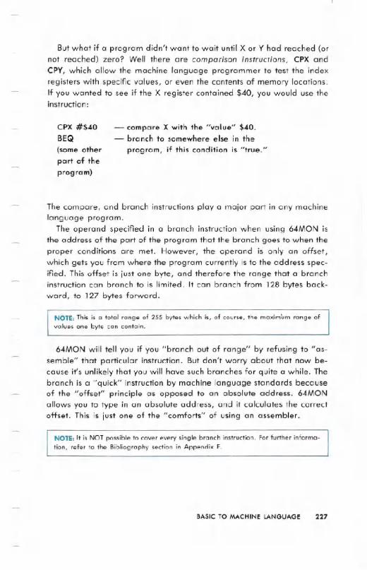
But what if a program didn't want to wait until X or Y had reached (ornot reached) zero? Well there are comparison instructions, CPX andCPY, which allow the machine language programmer to test the indexregisters with specific values, or even the contents of memory locations.If you wanted to see if the X register contained $40, you would use theinstruction:
CPX #$40BEQ
(some otherpart of theprogram)
- compare X with the "value" $40.- branch to somewhere else in the
program, if this condition is "true."
The compare, and branch instructions playa major part in any machinelanguage program.
The operand specified in a branch instruction when using 64MON isthe address of the part of the program that the branch goes to when theproper conditions are met. However, the operand is only an offset,which gets you from where the program currently is to the address spec-ified. This offset is just one byte, and therefore the range that a branchinstruction can branch to is limited. It can branch from 128 bytes back-ward, to 127 bytes forward.
NOTE: This is a total range of 255 bytes which is, of course, the maximum range ofvalues one byte can contain.
64MON will tell you if you "branch out of range" by refusing to "as_semble" that particular instruction. But don't worry about that now be-cause it's unlikely that you will have such branches for quite a while. Thebranch is a "quick" instruction by machine language standards becauseof the "offset" principle as opposed to an absolute address. 64MONallows you to type in an absolute address, and it calculates the correctoffset. This is just one of the "comforts" of using an assembler.
NOTE: It is NOT possible to cover every single branch instruction. For further informa-
tion, refer to the Bibliography section in Appendix F.
BASIC TO MACHINE LANGUAGE 227

SUBROUTINES
In machine language (in the same way as using BASIC), you can callsubroutines. The instruction to call a subroutine is JSR (Jump to Sub-Routine), followed by the specified absolute address.
Incorporated in the operating system, there is a machine languagesubroutine that will PRINT a character to the screen. The CBM ASCII
code of the character should be in the accumulator before calling thesubroutine. The address of this subroutine is $FFD2.
Therefore, to print "HI" to the screen, the following program shouldbe entered:
.A 1400 lDA #$48
.A 1402 JSR $FFD2
.A 1405 lDA #$49
.A 1407 JSR $FFD2
.A 140A lDA #$OD
.A 140C JSR $FFD2
.A 140F BRK
.G 1400
- load the C8M ASCII code of "H"
- print it- load the C8M ASCII code of "1"
- print that too- print a carriage return as well
- return to 64MON
- will print "HI" and return to 64MON
The "PRINT a character" routine we have just used is part of theKERNAl jump table. The instruction similar to GOTO in BASIC is JMP,which means JuMP to the specified absolute address. The KERNAl is along list of "standardized" subroutines that control All input and outputof the Commodore 64. Each entry in the KERNAlJMPs to a subroutine inthe operating system. This "jump table" is found between memory loca-tions $FF84 to $FFF5 in the operating system. A full explanation of theKERNAl is available in the "KERNAl Reference Section" of this manual.
However, certain routines are used here to show how easy and effectivethe KERNAl is.
let's now use the new principles you've just learned in another pro-gram. It will help you to put the instructions into context:
228 BASIC TO MACHINE LANGUAGE

This program will display the alphabet using a KERNALroutine. Theonly new instruction introduced here is TXATransfer the contents of the Xindex register, into the Accumulator.
.A 1400 LDX#$41
.A 1402 TXA
.A 1403 JSR $FFD2
.A 1406 INX
.A 1407 CPX #$5B
.A 1409 BNE $1402
.A 140B BRK
- X = CBM ASCII of "A"
-A=X- print character- bump count- have we gone past "Z" ?- no, go back and do more- yes, return to 64MON
To see the Commodore 64 print the alphabet, type the familiar com-mand:
.G 1400
The comments that are beside the program, explain the program flowand logic. If you are writing a program, write it on paper first, and thentest it in small parts if possible.
USEFUL TIPS FOR THE BEGINNER
One of the best ways to learn machine language is to look at otherpeoples' machine language programs. These are published all the timein magazines and newsletters. Look at them even if the article is for adifferent computer, which also uses the 6510 (or 6502) microprocessor.You should make sure that you thoroughly understand the code that youlook at. This will require perseverence, especially when you see a newtechnique that you have never come across before. This can be infuriat-ing, but if patience prevails, you will be the victor.
Having looked at other machine language programs, you MUSTwriteyour own. These may be utilities for your BASIC programs, or they maybe an all machine language program.
BASIC TO MACHINE LANGUAGE 229
You should also use the utilities that are available, either IN yourcomputer, or in a program, that aid you in writing, editing, or trackingdown errors in a machine language program. An example would be theKERNAL,which allows you to check the keyboard, print text, controlperipheral devices like disk drives, printers, modems, etc., managememory and the screen. It ;s extremely powerful and it is advisedstrongly that it is used (refer to KERNALsection, Page 268).
Advantages -of writing programs in machine languag-e:
1. Speed -Mac-hine language isthousands of times faster thanBASIC.
2. Tightness -A machine language program can be made totally"watertight," Le., the user can be made to do ONLYwhat theprogram allows, and no more. With a high level language, youare relying on the user not "crashing" the BASIC interpreter byentering, for example, a zero which later causes a:
hundreds, and in some cases
a high level language such as
?DIVISION BY ZERO ERROR IN LINE-830
READY..In essence, the computer can only be maximized by the machine lan-guage programmer.
APPROACHING A LARGE TASK
When approaching a large task in machine language, a certainamount of subconscious thought has usually taken place. You thinkabout how certain processes are carried out in machine language.When the task is started, it is usually a good idea to write it out onpaper. Use block diagrams of memory usage, functional modules ofcode required, and a program flow. Let's say that you wanted to write aroulette game in machine language. You could outline it something likethis:
230 BASICTO MACHINELANGUAGE

. Display title
. Ask if player requires instructions
. YES-display them-Go to START
. NO'-Go to START
. STARTInitialize everything
. MAINdisplay roulette table. Take in bets
. Spin wheel
. Slow wheel to stop. Check bets with result
. Informplayer
. Player any money left?
. YES-Go to MAIN
. NO-Inform user!, and go to START
This is the main outline. As each module is approached, you canbreak it down further. If you look' at a large indigestable problem assomething that con be broken down into small enough pieces to beeaten, then you'll be able to approach something that seems impossible,and have it all faU into place.
This process only improves with practice, so KEEPTRYING.
BASIC TO MACHINE LANGUAGE 231
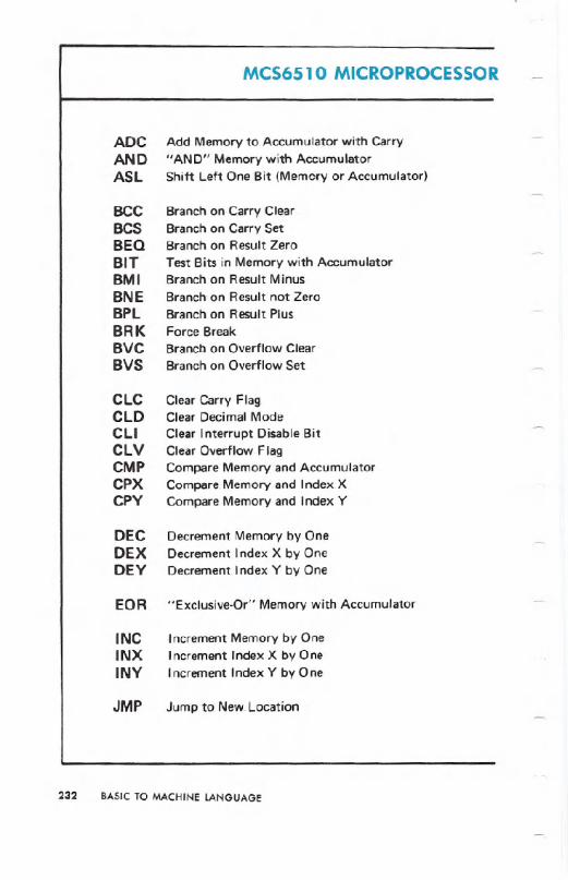
MCS6510 MICROPROCESSOR
ADCANDASl
BeCBCSBEQBITBMIBNEBPlBRKBVCBVS
ClCClDCliClVCMPCPXCPY
DECDEXDEY
EOR
INCINXINY
JMP
Add Memory to Accumulator with Carry"AND" Memory with AccumulatorShift Left One Bit (Memory or Accumulator)
Branch on Carry ClearBranch on Carry SetBranch on Result ZeroTest Bits in Memory with AccumulatorBranch on Result MinusBranch on Result not ZeroBranch on Result PlusForce BreakBrancb on Overflow ClearBranch on OverflowSet
Clear Carry FlagClear Decimal ModeClear Interrupt Disable BitClear Overflow FlagCompare Memory and AccumulatorCompare Memory and Index XCompare Memory and Index Y
Decrement Memory by OneDecrement Index X by OneDecrement Index Y by One
"Exclusive-Or" Memory with Accumulator
Increment Memoryby OneIncrement Index X by OneIncrement Index Y by One
Jump to New. Location
232 BASIC TO MACHINE LANGUAGE
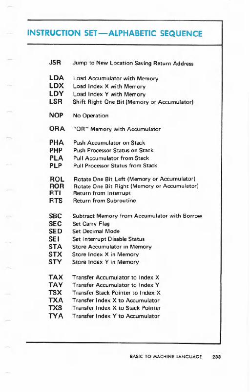
INSTRUCTION SET-ALPHABETIC SEQUENCE
JSR
LDALDXLDYLSR
NOP
ORA
PHAPHPPLAPLP
ROLRORRTIRTS
SBCSEeSEDSEISTASTXSTY
TAXTAYTSXTXATXSTYA
Jump to New location Saving Return Address
Load Accumulator with Memoryload Index X with MemoryLoad Index Y with MemoryShift Right One Bit (Memory or Accumulator)
No Operation
"OR" Memory with Accumulator
Push Accumulator on StackPush Processor Status on StackPull Accumulator from StackPull Processor Status from Stack
Rotate One Bit Left (Memory or Accumulator)Rotate One Bit Right (Memory or Accumulator)Return from InterruptReturn from Subroutine
Subtract Memory from Accumulator with BorrowSet Carry FlagSet Decimal Mode
Set Interrupt Disable StatusStore Accumulator in MemoryStore Index X in MemoryStore Index Y in Memory
Transfer Accumulator to Index XTransfer Accumulator to Index YTransfer Stack Pointer to Index XTransfer Index X to AccumulatorTransfer Index X to Stack PointerTransfer Index Y to Accumulator
BASICTO MACHINELANGUAGE 233

The following notation applies to this summary:
Note: At the top of each table is located in parentheses a
reference number (Ref: XX) which directs the user to
that Section in the MCS6500 Microcomputer Family
Programming Manual in which the instruction is defined
and discussed.
234 BASIC TO MACHINE LANGUAGE
A Accumulator
X, y Index Registers
M Memory
P ProcessorStatusRegisterS Stack Pointer
I Change
No Change
+ Add
/\ Logical AND
Subtract
:If Logical Exclusive Or
t Transfer from Stack
... Transfer to Stack
Transfer to
<- Transferfrom
V Logical OR
PC Program Counter
PCH Program Counter High
PCL Program Counter Low
OPER OPERAND
/I IMMEDIATE ADDRESSING MODE
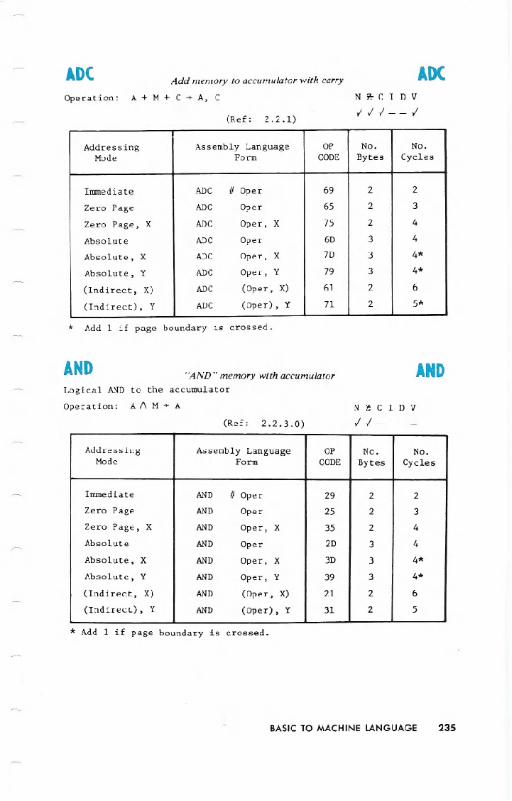
ADCAdd memo,y to accumulato, with carry
A + M + C ~ A, C
ADC
(Ref: 2.2.1)
Ni!-CIDV
111--1Operation:
* Add 1 if page boundary 19 crossed.
AND"AND" memo,y with accumulato, AND
Logical AND to the accumulator
Operation: A A M ~ A
(Ref: 2.2.3.0)
N ! C I D V
11----
* Add 1 if page boundary is crossed.
BASIC TO MACHINE LANGUAGE 235
Addressing Assembly Language OP No. No.Mode Form CODE Bytes Cycles
Immediate ADC IIOper 69 2 2
Zero Page ADC Oper 65 2 3
Zero Page, X ADC Oper, X 75 2 4
Absolute ADC Oper 6D 3 4
Absolute, X ADC Oper, X 7D 3 4*
Absolute, Y ADC Oper,Y 79 3 4*
(lndirec t, X) ADC (Oper, X) 61 2 6
(Indirect), Y ADC (Oper), Y 71 2 5*
Addressing Assembly Language OP No. No.Mode Form CODE Bytes Cycles
Immediate AND 1/Oper 29 2 2
Zero Page AND Oper 25 2 3
Zero Page, X AND Oper, X 35 2 4
Absolute AND Oper 2D 3 4
Absolute, X AND Oper, X 3D 3 4*
Absolute, Y AND Oper,Y 39 3 4*
(Indirect, X) AND (Oper, X) 21 2 6
(Indirect), Y AND (Oper), Y 31 2 5
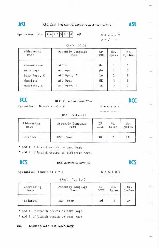
ASL ASL Shift Left One Bit (Memory or Accumulator) ASL
Operation: C <- ~ ...0N -c C I D V
/11---
(Ref: 10.2)
Bee BCC Branch on Carr.v Clear
Branch on C = 0
BeeOperation: N i!-C I D V
------(Ref: 4.1.1.3)
* Add 1 if branch occurs to same page.
* Add 2 if branch occurs to different page.
BeS BCS Branchon carryset Bes
Operation: Branch on C = 1 N i\ C I D V
------(Ref: 4.1.1.4)
* Add 1 if branch occurs to same page.
* Add 2 if branch occurs to next page.
236 BASIC TO MACHINE LANGUAGE
Addressing Assembly Language OP No. No.Mode Form CODE Bytes Cycles
Accumulator ASLA 0A 1 2
Zero Page ASL Oper 06 2 5
Zero Page, X ASL Oper, X 16 2 6
Absolute ASL Oper 0E 3 6
Absolute, X ASL Oper, X IE 3 7
Addressing Assembly Language OP No. No.Mode Form CODE Bytes Cycles
Relative BCC Oper 90 2 2*
Addressing Assembly Language OP 110. No.Mode Form CODE Bytes Cycles
Relative BCS Oper B 2 2*
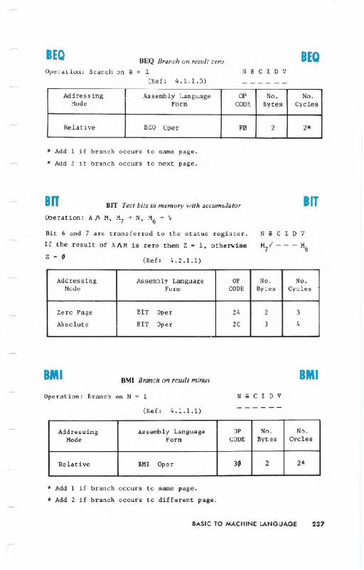
BEOBEQ Branch on result zero1
(Ref: 4.1.1. 5)
BEO
Operation: Branch on g N g C I D V
------
* Add 1 if branch occurs to same page.
* Add 2 if branch occurs to next page.
BIT BIT Test:bits in memory with accumulator BIT
Operation: A A M, M] ~ N, M6 ~ V
Bit 6 and ] are transferred to the status register.
If the result of A 1\M is zero then Z - 1, otherwise
Z - 0(Ref: 4.2.1.1)
BMI BMI Branch on result minus BMI
Operation: Branch on N = 1 N ~ C I D V
(Ref: 4.1.1.1)------
Addressing AssemblyLanguage OP No. No.Mode Form CODE Bytes Cycles
Relative BEQ Oper F0 2 2*
Addressing Assembly Language OP No. No.Mode Form CODE Bytes Cycles
Zero Page BIT Oper 24 2 3
Absolute BIT Oper 2C 3 4
Addressing Assembly Language OP No. No.Mode Form CODE Bytes Cycles
Relative BMI Oper 30 2 2*
* Add 1 if branch occurs to same page.
* Add 2 if branch occurs to different page.
BASIC TO MACHINE LANGUAGE 237
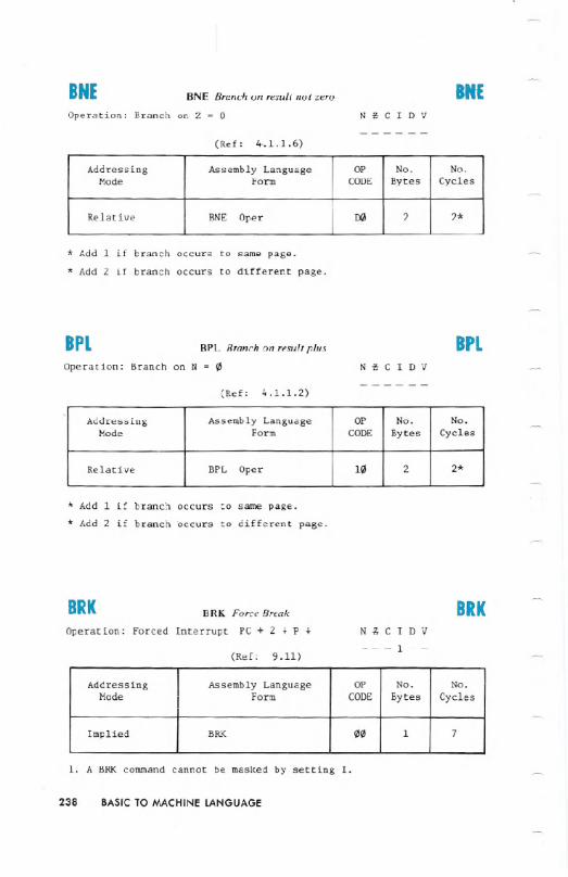
BNE BNE Branch on result not zero BNEOperation: Branch on Z - 0 NtCIDV
------(Ref: 4..1.1.6)
* Add 1 if branch occurs to same page.
* Add 2 if branch occurs to different page.
BPL BPL Branch on result plus BPL
Operation: Branch on N = 0 N~CIDV------
(Ref: 4.1.1.2)
* Add 1 if branch occurs to same page.
* Add 2 if branch occurs to different page.
BRK BRK Force Break IRK
Operation: Forced Interrupt PC + 2 ~ P ~
(Ref: 9.11)
N ~ C I D V
---1--
1. A BRK command cannot be masked by setting I.
238 BASIC TO MACHINE LANGUAGE
Addressing Assembly Language OP No. No.Mode Form CODE Bytes Cycles
Relative BNE Oper IX! 2 2*
Addressing Assembly Language OP No. No.Mode Form CODE Bytes Cycles
Relative BPL Oper 10 2 2*
Addressing Assembly Language OP No. No.Mode Form CODE Bytes Cycles
Implied BRK 00 1 7

Bye BVC Branchonoverflow clear
Operation: Branch on V = 0
ByeN~CIDV
(Ref: 4.1.1.8)------
* Add 1 if branch occurs to same page.
* Add 2 if branch occurs to different page.
ays BVS Branch on overflow set BYSOperation: Branch on V = 1 N !! C I D V
------(Ref: 4.1.1.7)
* Add 1 if branch occurs to same page.
* Add 2 if branch occurs to different page.
CLC CLC Clear carry flag eLeOperation: 0 ~ C N !! C I D V
(Ref: 3.0.2)--0---
BASIC TO MACHINE LANGUAGE 239
Addressing Assembly Language OP No. No.Mode Form CODE Bytes Cycles
Relative BVC Oper 50 2 2*
Addressing Assembly Language OP No. No.Mode Form CODE Bytes Cycles
Relative BVS Oper 70 2 2*
Addressing AssemblyLanguage OP No. No.Mode Form CODE BytE!s Cycles
Implied CLC 18 1 2
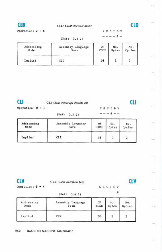
CLD CLD Clear decimal mode CLDOperation: IJ + D NtCIDV
(Ref: 3.3;2)(/1-
CLI CLI Clear interrupt disable bit CLI
Operation: IJ + I
(Ref: 3.2.2)
N ~ C I D V
---(,!--
CLV CLV Clear overflow flag CLVOperation: IJ + V
(Ref: 3.6.1)
NtCOIDV
(,!
240 BASICTO MACHINE LANGUAGE
Addressing Assembly Language OP No. No.}fode Form CODE Bytes Cycles
Implied CLD D8 1 2
Addressing Assembly Language OP No. No.Mode Form CODE Bytes Cycles.
Implied CLI 58 1 2
Addressing Assembly Language OP No. No.Mode Form CODE Bytes Cycles
Implied CLV B8 1 2

(MP CMPCompare memory and accumulator
Operation:A - M N ~ C I D V
CMP
(Ref: 4.2.1)111---
* Add 1 if page boundary is crossed.
(PX CPX Compare Memory and Index X (PX
Operation: X - M NcCIDV
111---(Ref: 7.8)
(py Cpy Compare memory and index Y CpyOpera~ion: Y - M N i!iC I D V
111---(Ref: 7.9)
BASICTO MACHINE LANGUAGE 241
Addressing Issembly Language OP No. No.Mode Form CODE Bytes Cycles
Immediate CMP #Oper C9 2 2
Zero Page CMP Oper C5 2 3
Zero Page, X CMP Ope r, X D5 2 4
Absolute CMP Oper CD 3 4
Absolute, X CMP Oper, X DD 3 4*
Absolute, Y CMP Oper,Y D9 3 4*
(Indirect, X) CMP (Oper, X) Cl 2 6
(Indirect), Y CMP (Oper), Y Dl 2 5*
Addressing Assembly Language OP No. No.Mode Form CODE Bytes Cycles
Immediate CPX #Oper E0 2 2
Zero Page CPX Oper E4 2 3
Absolute CPX Oper EC 3 4
Addressing Assembly Language OP No. No.Mode Form CODE Bytes Cycles
Immediate CPY # Oper C0 2 2
Zero Page CPY Oper C4 2 3
Absolute CPY Oper CC 3 4

DEC DEC Decrement memory by one DECOperation: M - 1 + M N~CIDV
//----(Ref: 10.7)
DEX DEX Decrement index X bv one DEXOperation:X - 1 + X
(Ref: 7.6)
N ~ C I D V
//----
DEY DEY Decrement index Y by one DEYOperation: Y - 1 + Y
(Ref: 7.7)
N ~ C I D V
//----
242 BASIC TO MACHINE LANGUAGE
Addressing Assembly Language OP No. No.Mode Form CODE Bytes Cycles
Zero Page DEC Oper C6 2 5
Zero Page, X DEC Oper, X D6 2 6
Absolute DEC Oper CE 3 6
Absolute, X DEC Oper, X DE 3 7
Addressing Assembly Language OP No. No.Mode Form CODE Bytes Cycles
Implied DEX CA 1 2
Addressing AssemblyLanguage OP No. No.Mode Form CODE Bytes Cycles
Implied DEY 88 1 2

EOR EOR "Exclusive-Or" memory with accumulator EOROperation: A ¥ M ~ A
(Ref: 2.2.3.2)
N e C I D V
11----
* Add 1 if page boundary is crossed.
INC INC Increment memory by one INC
Operation:M + 1 ~ M N e C I D V11----
(Ref: 10.6)
INX INX Increment Index X by one
Operation: X + 1 ~ X
INXN i5 C I D V
11----(Ref: 7.4)
BASICTO MACHINE LANGUAGE 243
Addressing Assembly Language OP No. No.Mode Form CODE Bytes Cycles
Immediate EOR # Oper 49 2 2
Zero Page EOR Oper 45 2 3
Zero Page, X EOR Oper, X 55 2 4
Absolute EOR Oper 4D 3 4
Absolute, X EOR Oper, X 5D 3 4*
Absolute, Y EOR Oper, Y 59 3 4*
(Indirect, X) EOR (Oper, X) 41 2 6
(Indirect) ,Y EOR (Oper) , Y 51 2 5*
Addressing Assembly Language OP No. No.Mode Form CODE Bytes Cycles
Zero Page INC Oper E6 2 5
Zero Page, X INC Oper, X F6 2 6
Absolute INC Oper EE 3 6
Absolute, X INC Oper, X FE 3 7
Addressing Assembly Language OP No. No.Mode Form CODE Bytes Cycles
Implied INX E8 1 2
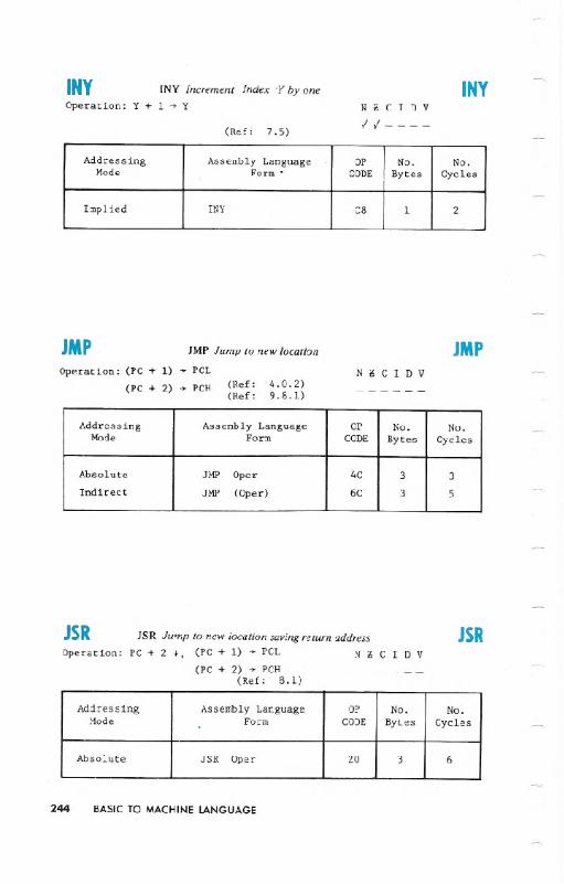
INY INY Increment Index .yby one INYOperation: Y + 1 ~ Y
(Ref: 7.5)
N g C I D V
11----
JMP JMP Jump to new location
PCL
JMPOp..ration: (PC + 1)
(PC + 2) PCH (Ref:(Ref:
4.0.2)9.8.1)
------
JSR JSR Jump tonew locationsavingreturnaddress JSROperation:PC + 2 +, (PC+ 1) ~ PCL N g C I D V
(PC+ 2)~ PCH _ _ _ _ _ _(Ref: 8.1)
244 BASIC TO MACHINE LANGUAGE
Addressing Assembly Language OP No. No.Mode Form' CODE Bytes Cycles
Impl ied INY C8 1 2
Addressing Assembly Language OP No. No.Mode Form CODE Bytes Cycles
Absolute JMP Oper 4C 3 3
Indirect JMP (Oper) 6C 3 5I
Addressing AssemblyLanguage OP No. No.Mode Form CODE Bytes Cycles
Absolute JSR Oper 20 3 6

LDA LOA Loadaccumulator with memory LDA'Operation: M ... A
(Ref: 2.1.1)
N;;CIDV
11----
* Add 1 'if page boundary is crossed.
LDX LDXLoadindex X with memoryOperation: M'" X
LDX
(Ref: 7.0)
N i! C I D V
11----
* Add 1 when page boundary is crossed.
BASIC TO MACHINE LANGUAGE 245
Addressing Assembly Language OP No. No.Mode Form CODE Bytes Cycles
Immediate LDA # Oper A9 2 2
Zero Page LDA Oper AS 2 3
Zero Page, X LDA OpeT, X BS 2 4
Absolute LDA Oper AD 3 4
Absolute, X LDA .Oper, X BD 3 4*
Absolute, Y LDA Oper, Y B9 3 4*
(Indirect, X) LDA (Oper, X) Al 2 6
(Indirect), Y LDA (Oper), Y Bl 2 5*
Addressing Assembly Language OP No. No.Mode Fo.rm CODE Bytes Cycles
.Immediate LDX /IOper A2 2 2
.ZeroPage LDX Oper A6 2 3
.Zero Page, Y LDX Oper,Y B6 2 4
Absolute LDX Oper AE 3 4
. Absolute, Y LDX Oper,Y BE 3 4*

LDY LDY Load index Y with memory LDY
Operation: M + Y N!!CIDV
II -- ---(Ref: 7.1)
* Add 1 when page boundary is crossed.
LSR LSR Shift. right one bit (memory or accumulator) .LSR
Operation: 0 -.+ ~ - C N!!CIDV
011---.(Ref: 10.1)
NOP No operation
Operation: No Operation (2 cycles)
NOP NOPN!!CIDV
------
246 BASIC TO MACHINE LANGUAGE
Addressing Assembly Language OP No. No.Mode Form CODE Bytes Cycles
Immediate LDY # Oper A0 2. 2
Zero Page LDY Oper A4 2 3
Zero Page, X LDY Oper, X B4 2 4
Absolute LDY Oper AC 3 4
Absolute, X LDY Oper, X BC 3 4*
Addressing Assembly Language OP No. No.Mode Form CODE Bytes Cycles
Ac=umulator LSR A 4A 1 2
Zero Page LSR Oper 46 2 5
Zero Page, X LSR Oper, X 56 2 6
Absolute LSR Oper 4E 3 6
Absolute, X LSR Oper, X 5E 3 7
Addressing AssemblyLanguage OP No. No.Mode Form CODE Bytes Cycles
Implied NOP EA 1 2

ORA ORA "OR" memory with accumulator ORAoperation: A V M ~ A
(Ref: 2.2.3.1)
N;;CIDV
11----
* Add 1 on page crossing
PHA 'PHA Push-accumulator un stack PHAOperation: A { N ;; C I D V
(Ref: 8.5)------
PHP PHP Push processor status on stack PHPoperation: P{ Ni!CIDV
(Ref: 8.11)------
BASIC TO MACHINE' LANGUAGE 247
Addressing Assembly Language OP No. No.Mode Form CODE Bytes Cycles
Iuunediate ORA #oper 09 2 2
Zero Page ORA Oper 05 2 3
Zero Page, X ORA Oper, X 15 2 4
Absolute ORA Oper 0D 3 4
Absolute, X ORA ope'r,X lD 3 4*
Absolute, Y ORA Oper,Y 19 3 4*
(Indirect, X) ORA (Oper, X) 01 2 6
(Indirect), Y ORA (Oper), Y 11 2 5
Addressing Assembly Language OP No. No.Mode Form CODE Bytes Cycles
Implied PHA 48 1 3
Addressing AssemblyLanguage OP No. No.Mode Form CODE Bytes Cycles
Implied PHP 08 1 3

PLA PLA Pull accumulator from stack PLAOperation: A t
(Ref: 8.6)
N iI C I D V
11----
'LP PLP Pull processor status from stack PLPOperation: P t NilCIDV
(Ref: 8.12)From Stack
ROL ROL Rotate one hit left (memory or accumulator) ROL
Operation: N j1; C I D V
111---(Ref: 10.3)
.248 BASIC TO MACHINE LANGUAGE
Addressing Assembly Languag.! OP No. No.Mode Form CODE Bytes Cycles
Implied PLA 68 1 4
Addressing Assembly Language OP No. No.Mode Form CODE Bytes Cycles
Implied PLP 28 1 4
Addressing Assembly Language OP No. No.Mode Form CODE Bytes Cycles
Accumulator ROL A 2A 1 2
Zero Pge ROL Oper 26 2 5
Zero Page, X ROL Oper, X 36 2 6
Absolute ROL .Ope.r 2E 3 6
Absolute, X ROL 'Oper, X 3E 3 7

ROR ROR Rotate one bit right (memory or accumulator) ROR
Operation: NiSCIDV
-/-/-/---
Note: ROR instruction is available on MCS650X micro-
processors after June, 1976.
RTI RTf Return from interrupt RTI
Operation: pt PCt N is C I D V
(Ref: 9.6)From Stack
RTS RTS Return from subroutine RTS
Operation: PCt, PC + l~ PC N is C I D V
(Ref: 8.2)------
BASIC TO MACHINE LANGUAGE 249
Addressing Assembly Language OP No. No.
Mode Form CODE Bytes Cycles
Accumulator RORA 6A 1 2
Zero Page ROR Oper 66 2 5
Zero Page,X ROR Oper,X 76 2 6
Absolute ROR Oper 6E 3 6
Absolute,X ROR Oper,X 7E 3 7
Addressing Assembly Language OP No. No.Morle Form CODE Bytes Cycles
Implied RTI 40 1 6
Addressing AssemblyLanguage OP No. No.
Mode Form CODE Bytes Cycles
Implied RTS 60 1 6

S8C SBCSBC Subtract memory {rom accumulator with borrow
Operation: A - M - C ~ A N ~ C I D V
Note: C= Borrow (Ref: 2.2.2) .' .' .'--.'
* Add 1 when page boundary is crossed.
SEC SEC Set carry flag SECOperation: 1 ~ C
(Ref: 3.0.1)
N i5 C 1 D V
--1---
SED SED Set decimal mode SEDOperation: 1 ~ D
(Ref: 3.3.1)
N i!C I D V
1-
250 BASIC TO MACHINE LANGUAGE
Addressing Assembly Language OP No. No.Mode Form CODE Bytes Cycles
ImmediateSBC #Oper E9 2 2
Zero Page SBC Oper E5 2 3
Zero Page, X SBC Oper,X F5 2 4
Absolute SBC Oper ED 3 4
Absolute, X SBC Oper,X FD 3 4*
Absolute, Y SBC Oper,Y F9 3 4*
(Indirect, X) SBC (Oper, X) El 2 6
(Indirect), Y SBC (Oper), Y Fl 2 5*
Addressing Assembly Language OP No. No.Mode Form CODE Bytes Cycles
Implied SEC 38 1 2
Address ing Assembly Language OP No. No.Mode Form CODE Bytes Cycles
Implied SED F8 1 2

SEI SEISetinterrupt disablestatus
Operation: 1 ~ 1
SEI
N i!iC 1 D V
---1--(Ref: 3.2.1)
SfA STA Store accumulator in memory SfAOperation: A ~ M N i!iC I D V
------(Ref: 2.l.2)
STX STX Store index X in memory STXOperation: X ~ M N i!iC I D V
------(Ref: 7.2)
BASIC TO MACHINE LANGUAGE 2S 1
Addressing Assembly Language OP No. No_.Mode FOTm CODE Bytes Cycles
Implied SEI 78 1 2
Addressing Assembly Language OP No. No.Mode Form CODE Bytes Cycles
Zero Page STA Oper 85 2 3
Zero Page, X STA Oper, X 95 2 4
Absolute STA Oper 8D 3 4
Absolute, X STA Oper, X 9D 3 5
Absolute, Y STA Oper,Y 99 3 5
(Indirect, X) STA (Oper, X) 81 2 6
(Indirect), Y STA (Oper), Y 91 2 6
Addressing Assembly Language OP No. No.Mode Form CODE Bytes Cycles
Zero Page STX Oper 86 2 3
Zero Page, Y STX Oper,Y 96 2 4
Absolute STX Oper 8E 3 4

STY STY StoreindexY inmemory
Operation: Y ~ M
STYNaCIDV
------(Ref: 7.3)
TAX TAX TransferaccumulatortoindexXOperation: A ~ X N a C I D v
11----
TAX
(Ref: 7.11)
TAYT A Y Transfe." accumulator to index Y
TAYOperation: A ~ Y N a C I D v
11----(Ref: 7.13)
252 BASIC TO MACHINE LANGUAGE
Addressing Assembly Language OP No. No.Mode Form CODE Bytes Cycles
Zero Page STY Oper 84 2 3
Zero Page, X STY Oper, X 94 2 4
Absolute STY Oper 8C 3 4
Addressing Assembly LanEuage OP No. No.Mode Form CODE Bytes Cycles
Implied TAX AA 1 2
Addressing Assembly Language OP No. No.Mode Form CODE Bytes Cycles
Implied TAY A8 1 2

TSX TSX TransferstackpointertoindexX TSX
Operation: S ~ X N ~ C I D V
(Ref: 8.9)11----
TXA TXA TransferindexX toaccumulator
Operation: X ~ A
TXA
(Ref: 7.l2)
N~CIDV
11----
TXS TXS TransferindexX tostackpointer TXS
Operation: X ~ S N i!C I D V
(Ref: 8.8)-------
TYA TYA TransferindexY toaccumulator TVAOperation: Y ~ ANi! C I D V
(Ref: 7.14)11----
BASIC TO MACHINE LANGUAGE 253
Addressing Assembly Language OP No. No.Mode Form CODE Bytes Cycles
Implied TSX BA 1 2
Addressing Assembly Language OP No. No.Mode Form CODE Bytes Cycles
Implied TXA 8A 1 2
Addressing Assembly Language OP No. No.Mode Form CODE Bytes Cycles
Implied TXS 9A 1 2
Addressing Assembly Language OP No. No.Mode Form CODE Bytes Cycles
Implied TYA 98 1 2

INSTRUCTION ADDRESSING MODES AND
ADCANDASlBCCBCSBEOBITBMIBNEBPLBRKBVCBVSClCClDCliClVCMPCPXCPVDECDEXDEVEORINCINXINYJMP
x > x >
...
f_ >
:sX c
254 BASICTO MACHINE LANGUAGE
234234
2 5 '6
3
2342 32 3
5 6
2345 6
4 4*4* 6 5*4 4* 4 * 6 5*6 7
2**.2** .2** .
42** .2**.2**.
2*'\.2** .
2222
4 4* 4 *. . 6 5*446 7
22
4 4* 4* . 6 5-6 7
22
3 . . . . . . 5
· Add one cycle if indexing across page boundary.. Add one cycle if branch is taken, Add one additional

RELATED EXECUTIONTIMES (in clock cycles)-
..a»a.
x> x> -!"a» .... x>-..,.. a»a»& .... ..- .., = == ._ .., .., .., .. .. .. " GI ..E i A. A. A. ' . f f .:= E 0 0 0 0 00= - - 0"'''''''-'i1'''e E ._ N N N - = =
JSR 6LDA 2 3 4 4 4* 4* . 6 5* .LDX 2 3 4 4 4* .LDY 2 3 4 4 4* .LSR 2 5 6 6 7NOP 2ORA 2 3 4 4 4* 4* . 6 5* .PHA 3PHP 3PLA 4PLP 4ROL 2 5 6 6 7ROR 2 5 6 6 7RTI 6RTS 6sse 2 3 4 4 4* 4* . 6 S* .sEe 2SED 2SEI 2STA 3 4 4 5 5 6 6STX 3 4 4STY 3 4 4TAX 2TAY 2TSX 2TXA 2TXS 2TYA 2
if branching operation crosses page boundary
BASIC TO MACHINE LANGUAGE 255

00 - BRK 20 - JSR
01 - ORA- (Indirect,X) .21 -AND - (Indirect,X)
02 - Future Expansion 22 - Future Expansion
03 - Future Expansion 23 - Future Expansion
04 - Future Expansion 24 - BIT - Zero Page
05 - ORA- Zero Page 25 - AND - Zero Page
06 - ASL - Zero .Page 26 - ROL - Zero Page
07 - Future Expansion 27 - Future Expansion
08 - PHP 28 - PLP
09 - ORA-Immediate .29 - AND - Immediate
.0A - ASL - Accumulator 2A - ROL - Accumulator
0B - Future Expansion 2B - Future Expansion
0c - Future Expansion 2C - BIT - Absolute
0D - ORA- Absolute 2D - AND - Absolute
0E - ASL - Absolute 2E - ROL - Absolute
0F - Future Expansion 2F - Future Expansion
10 - .BPL 30 - 'BMl
11 - ORA- (Indirect),Y 31 - AND - (Indirect),Y
.12 - Future 'Expansion 32 - FutureExpansion
13 - Future Expansion 33 - Future Expansion
.14 - Future Expansion 34 - Future Expansion
15 - ORA - Zero Page,X 35 - AND - Zero Page,X
16 - ASL - Zero Page;X 36 - ROL - Zero Page,X
17 - Future Expansion 37 - Future Expansion
18 - CLC :38 - SEC
19 - ORA- -Absolute, Y 39 - AND - Abso1ute,Y
1A - Future Expansion 3A - FutureExpansion
1B - Future Expansion 3B - Future Expansion
1C - Future Expansion 3C - Future Expansion
1D -ORA - Abso1ute,X 3D - AND - Abso1ute,X
1E - ASL - Abso1ute,X 3E - ROL - Absa1ute,X
IF- Future Expansion 3F - .Future Expansion
256 BASICTO MACHINELANGUAGE
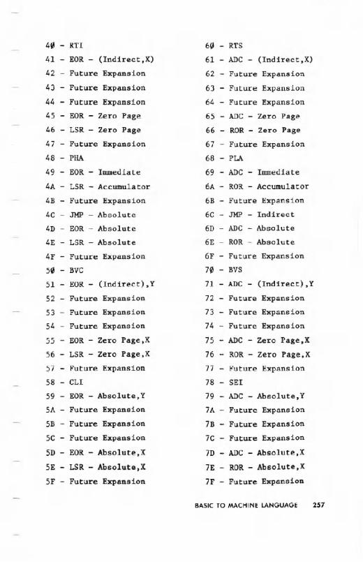
40 - RTI 60 - RTS
41 - EOR - (Indirect,X) 61 - ADC - (Indirect,X)
42 - Future Expansion 62 - Future Expansion
43 - Future Expansion 63 - Future Expansion
44 - Future Expansion 64 - Future Expansion
45 - EOR - Zero Page 65 - ADC - Zero Page
46 - LSR - Zero Page 66 - ROR - Zero Page
47 - Future Expansion 67 - Future Expansion
48 - PHA 68 - PLA
49 - EOR - Immediate 69 - ADC - Immediate
4A - LSR - Accumulator 6A - ROR - Accumulator
4B - FutureExpansion 6B - Future Expansion
4C - JHP - Absolute 6C - JHP - Indirect
4D - EOR - Absolute 6D - ADC - Absolute
4E - LSR - Absolute 6E - ROR - Absolute
4F - Future Expansion 6F - Future Expansion
50 - BVC 70 - BVS
51 - EOR - (Indirect),Y 71 - ADC - (Indirect),Y
52 - Future Expansion 72 - Future Expansion
53 - Future Expansion 73 - Future Expansion
54 - Future Expansion 74 - Future Expansion
55 - EOR - Zero Page,X 75 - ADC - Zero Page,X
56 - LSR - Zero Page,X 76 - ROR - Zero Page. X
57 - Future Expansion 77 - Future Expansion
58 - CLl 78 - SEI
59 - EOR - Absolute.Y 79 - ADC - Abso1ute.Y
SA - Future Expansion 7A - Future Expansion
5B - Future Expansion 7B - Future Expansion
5C - Future Expansion 7C - Future Expansion
5D - EOR - Absolute,X 7D - ADC - Absolute,X
5E - LSR - Absolute,X 7E - ROR - Absolute,X
SF - Future Expansion 7F - Future Expansion
BASIC TO MACHINE LANGUAGE 257

80 - Futur.e Expansion A0 - LDY - Immediate
81 - STA - (Indirect, X) A1 - LDA - (Indirect,X)
82 - Future Expansion A2 - LDX - Immediate
83 - Future Expansion A3 - Future Expansion
84 - STY - Zero Page A4 - LDY - Zero Page
85 - STA - Zero Page AS - LDA - Zero Page
86 - STX - Zero Page A6 - LDX - Zero Page
87 - Future Expansion A7 - Future Expansion
88 - DEY A8 - TAY
89 - Future Expansion A9 - LDA - Immediate
8A - TXA AA - TAX
8B - Future Expansion AB - Future Expansion
8C - STY - Absolute AC - LDY - Absolute
8D - STA - Absolute AD - LDA - Absolute
8E - STX - Absolute AE - LDX - Absolute
8F - Future Expansion AF - Future Expansion
90 - BCC B0 - BCS
91 - STA - (Indirect),Y B1 - LDA - (Indirect),Y
92 - Future Expansion B2 - Future Expansion
93 - Fuure Expansion B3 - Future Expansion
94 - STY - Zero Page,X B4 - LDY - Zero Page,X
95 - STA - Zero Page,X B5 - LDA - Zero Page,X
96 - STX - Zero Pge,Y B6 - LDX - Zero Page,Y
97 - Future Expansion B7 - Future Expansion
98 - TYA B8 - CLV
99 - STA - Absolute,Y B9 - LDA - Abso1ute,Y
9A - TXS BA - TSX
9B - Future Expansion BB - Future Expansion
9C - Future Expansion BC - LDY - Abso1ute,X
9D - STA - Absolute,X BD - LDA - Absolute,X
9E - Future Expansion BE - LDX - Abso1ute,Y
9F - Future Expansion BF - Future Expansion
258 BASICTO MACHINELANGUAGE
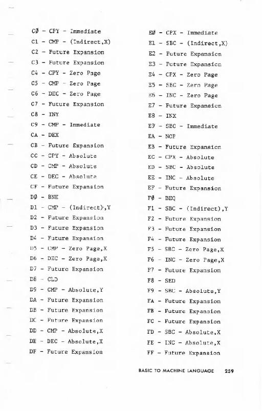
c0 - Cpy - Iwmediate E - CPX - Immediate
Cl - CMP - (Indirect, X) El - SBe - (Indirect,X)
C2 - Future Expansion E2 - Future Expansion
C3 - Future Expansion E3 - Future Expansion
C4 - CPY - Zero Page E4 - CPX - Zero Page
C5 - CMF - Zero Page E5 - SBC - Zero Page
C6 - DEC - Zero Page E6 - INC - Zero Page
e7 - Future Expansion E7 - Future Expansion
C8 - INY E8 - INX
C9 - CMP - Immediate Eg - SBC - Immediate
CA - DEX EA - NOP
CB - Future Expansion EB - Future Expansion
ec - CPY - Absolute EC - CPX - Absolute
CD - CMP - Absolute ED - SBC - Absolute
CE - DEC - Absolute EE - INC - Absolute
CF - Future Expansion EF - Future Expansion
D0 - BNE F0 - BEQ
Dl - CMP - (Indirect},Y Fl - SBC - (Indirect),Y
D2 - Future Expansion F2 - Future Expansion
D3 - Future Expansion F3 - Future Expansion
D4 - Future Expansion F4 - Future Expansion
D5 - eMP - Zero Page,X F5 - SBC - Zero Page,X
D6 - DEC - Zero Page,X F6 - INC - Zero Page,X
D7 - Future Expansion F7 - Future Expansion
D8 - CLD F8 - SED
D9 - eMP - Absolute,Y F9 - SBC - Absolute,Y
DA - Future Expansion FA - Future Expansion
DB - Future Expansion FE - Future Expansion
DC - Future Expansion FC - Future Expansion
DD - CMF - Absolute,X FD - SBC - Absolute,X
DE - DEC - Absolute,X FE - INC - Absolute,X
DF - Future Expansion FF - Future Expansion
BASICTO MACHINELANGUAGE 259
MEMORY MANAGEMENT ON THECOMMODORE 64
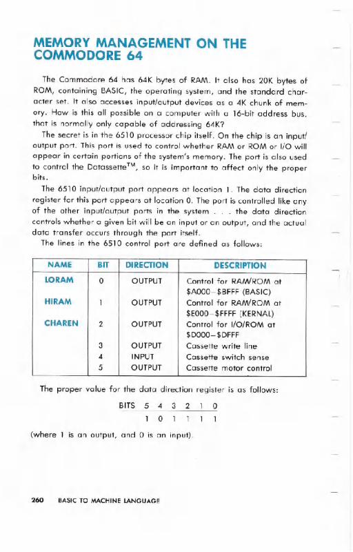
The Commodore 64 has 64K bytes of RAM. It also has 20K bytes ofROM, containing BASIC, the operating system, and the standard char-acter set. It also accesses input/output devices as a 4K chunk of mem-ory. How is this all possible on a computer with a 16-bit address bus,that is normally only capable of addressing 64K?
The secret is in the 6510 processor chip itself. On the chip is an input/output port. This port is used to control whether RAM or ROM or I/O willappear in certain portions of the system's memory. The port is also usedto control the Datassette TM,so it is important to affect only the properbits.
The 6510 input/output port appears at location 1. The data direction
register for this port appears at location O. The port is controlled like anyof the other input/output ports in the system . . . the data directioncontrols whether a given bit will be an input or an output, and the actualdata transfer occurs through the port itself.
The lines in the 6510 control port are defined as follows:
The proper value for the data direction register is as follows:
BITS 5 4 3 2 1 0
1 0 1 1 1 1
(where 1 is an output, and 0 is an input).
260 BASIC TO MACHINE LANGUAGE
NAME BIT DIRECTION DESCRIPTION
LORAM 0 OUTPUT Control for RAM/ROM at$AOOO-$BFFF (BASIC)
HIRAM 1 OUTPUT Control for RAM/ROM at
$EOOO-$FFFF(KERNAl)CHAREN 2 OUTPUT Control for I/O/ROM at
$DOOO-$DFFF3 OUTPUT Cassette write line4 INPUT Cassette switch sense5 OUTPUT Cassette motor control

This gives a value of 47 decimal. The Commodore 64 automaticallysets the data direction_ register to this value.
The control lines, in general, perform the function given in their de-scriptions. However, a combination of control lines are occasionally usedto get a particular memory configuration.
LORAM (bit 0) can generally be thought of as a control line whichbanks the 8K byte BASIC ROM in and out of-the microprocessor addressspace. Normally, this line is HIGH for BASIC operation. If this line isprogrammed LOW; the BASIC ROM will disappear from the memorymap and b~ replaced by 8K bytes of RAM from $AOOO-$BfFF.
HIRAM (bit 1) can generally be thought of as a control line whichbanks the 8K byte KERNALROM in and out of the microprocessor ad-dress space. Normally, this line is HIGH for BASIC operation. If this lineis programmed LOW, the KERNALROM will disappear from the memorymap and be replaced- by 8K bytes of RAM from $EOOO-$FFFF.
CHAREN (bit 2) is used only to bank the 4K byte character generatorROM in or out of the microprocessor address space. From the processorpoint of view, the character ROM occupies the same address space asthe I/O devices ($DOOO-$DFFF). When the CHAREN line is set to 1 (as isnormal), the I/O devices appear in the microprocessor address space,and the character ROM is not accessable. When the CHAREN bit is
cleared to 0, the character ROM appears in the processor addressspace, and the I/O devices are not accessable. (The microprocessor onlyneeds to access the character ROM when downloading the character setfrom ROM to RAM. Special care is needed for this . . . see the sectionon PROGRAMMABLECHARACTERSin the GRAPHICS chapter). CHARENcan be overridden by other control lines in certain memoryconfigurations. CHAR EN will have no effect on any memoryconfiguration without I/O devices. RAM will appear from $DOOO-$DFFFinstead.
NOTE: In any memory. map containing-ROM, a WRITE (a POKE) to a ROM location willstare data in the RAM "under" the ROM. Writing to a ROM location stores data in the
"hidden" RAM. For example. this allows a hi-resolution screen to be kept underneatha ROM, and be changed without- having to bank the screen back into the processor
address space. Of course a READ of a ROM location will return the contents of theROM, not the "hidden" RAM.
BASIC TO MACHINE LANGUAGE 261
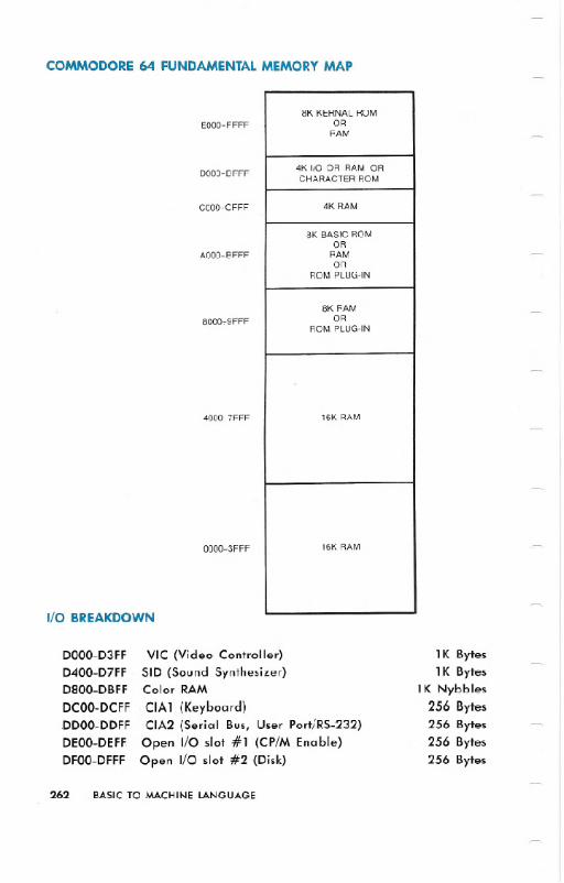
COMMODORE 64 FUNDAMENTALMEMORY MAP
I/O BREAKDOWN
DOOO-D3FF
D400-D7FF
D800-DBFF
DCOO-DCFF
DDOO-DDFF
DEOO-DEFF
DFOO-DFFF
EOOO-FFFF
DOOO-DFFF
COOO-CFFF
AOOO-BFFF
8000~9FFF
4000-7FFF
0000-3FFF
VIC (Video Controller)
SID (Sound Synthesizer)Color RAM
CIA1 (Keyboard)CIA2 (Serial Bus, User Port/RS--232)
Open I/O slot #1 (CP/M Enable)Open I/O slot #2 (Disk)
262 BASIC TO MACHINE LANGUAGE
1K Bytes1K Bytes
1K Nybbles256 Bytes256 Bytes256 Bytes256 Bytes
8K KERNAL ROMOR
RAM
4K I/O OR RAM ORCHARACTER ROM
4K RAM
8K BASIC ROMOR
RAMOR
ROM PLUG.IN
8K RAMOR
ROM PLUG.IN
16K RAM
16K RAM

The two open I/O slots are for general purpose user I/O, special pur-
pose I/O cartridges (such as IEEE), and have been tentatively.designatedfor -enabling the Z-80 cartridge (CP/M option) and for interfacing to alow-cost high~speed disk. system.
.The system provides for "auto-start" of the program in a Commodore
64 Expansion Cartridge. The cartridge program is started if the first ninebytes of the cartridge ROM starting at location 32768 ($8000) containspecific data. The first two bytes must hold the Cold Start vector to be
used by the cartridge program. The next two bytes at 32770 ($8002)
must be the Warm Start vector used by the cartridge program. The nextthree bytes must be the letters, CBM; with bit 7 set in each letter. Thelast two bytes must be the digits "80" in PET ASCII.
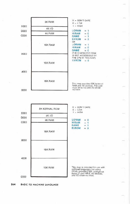
COMMODORE 64 MEMORY MAPS
The following tables list the various memory :configurations availableon the COMMODORE 64, the states of the control lines which select each
memory map, and .the intended use of each map.
EOOO
DOOO
COOO
AOOO
8000.
4000
0000
x =DON'TCAREo = LOW1 =HIGH
LORAM = 1HIRAM = 1GAME = 1EXROM = 1
This is Ihe default BASIC memorymap whiCh provides BASIC 2.0 and38K contiguous bytes of user RAM.
BASIC TO MACHINE LANGUAGE. 263
8KKERNAL ROM
4KI/O
4K RAM (BUFFER)
8K BASIC ROM
8K RAM
16K RAM
16K RAM
EOOO
0000
COOO
8000
4000
0000
EOOO
0000
COOO
8000
4000
264 BASIC TO MACHINE LANGUAGE
0000
x = DON'T CAREo = LOW1 = HIGH
LORAM = 1HIRAM = 0GAME = 1EXROM = XORLORAM' = 1HIRAM = 0GAME = 0(THE CHARACTER ROMIS NOT ACCESSIBLE BYTHE CPU IN THIS MAP)EX ROM. = 0
This map provides 60K bytes ofRAM and I/O devices. The usermust write his own I/O driverroutines.
x = DON'T CAREo = LOW1 = HIGH
LORAMHIRAMGAMEEXROM
o11X
This map is intended for use withsoft load. languages (includingCP/M), providing 52K contiguousbytes of user RAM, I/O devices,and I/O driver routines.
8K RAM
4KI/O
4K RAM
16K RAM
16K RAM
16K RAM
8K KERNAL ROM
4KI/O
4K RAM
16K RAM
16K RAM
16K RAM

EOOO
0000
COoo
AOOO
8000
4000
0000
x = DON'T CAREO=lOW1 = HIGH
LORAM = 1HIRAM = 1GAME = 1EXROM = 0
This is the standard configurationfor a BASIC system with a BASICexpansion ROM. This map provides32K contiguous bytes of user RAMand up to 8K bytes of BASIC"enhancement. ..
BASIC TO MACHINE LANGUAGE 265
x = DON'TCAREO=lOW
I
16K RAM
I
1 = HIGH
LORAM = 0COOO HIRAM = 0
GAME = 1EXROM = X
16KRAM I ORLORAM = 0HIRAM = 0
8000
I I
GAME =XEXROM = 0
16KRAM
4000
16KRAM I This mapgivesaccessto all 64Kbytes of RAM.The1/0devicesmust be bankedbackinto theprocessor'saddressspacefor any
0000 . . I/O operation.
8K KERNAL ROM
4KI/O
4K RAM (BUFFER)
8K BASIC ROM
8K ROM CARTRIDGE(BASIC EXP)
16K RAM
16K RAM

EOOO
0000
COOO
AOOO
8000
4000
0000
EOOO
0000
COOO
8000
4000
0000
266 BASIC TO MACHINE LANGUAGE
x = DON'T CAREo = LOW1 = HIGH
LORAM = 0HIRAM = 1GAME = 0EXROM = 0
This map provides 40K contiguousbytes of user RAMand up to 8Kbytes of plug.in ROM for specialROM.based applications which don'trequire BASIC.
x = DON'TCAREo = LOW1 = HIGH
LORAM = 1HIRAM = 1GAME = 0EXROM = 0
This map provides 32K contiguousbytes of user RAM and up to 16Kbytes of plug.in ROM for specialROM.based applications which don'trequire BASIC (word processors,other languages, etc.).
8K KERNAL ROM
4KII0
4K RAM (BUFFER)
8K ROM (CARTRIDGE)
8K RAM
16K RAM
16K RAM
8K KERNAL ROM
4KIJO
4K RAM (BUFFER)
16K ROM (CARTRIDGE)
16K RAM
16K RAM
EOOO
DOOO
COOO
AOOO
8000
4000
1000
0000
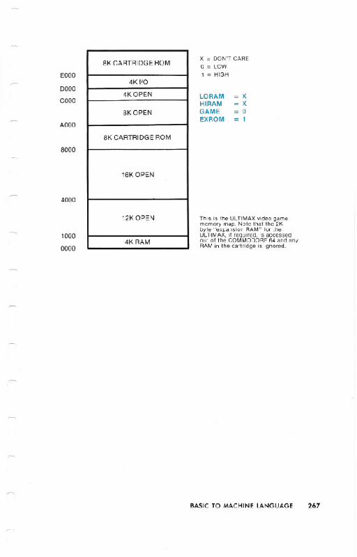
x = DON'TCAREo = LOW1 = HIGH
LORAM = XHIRAM = XGAME = 0EXROM = 1
This is the ULTIMAX video gamememory map. Note that the 2Kbyte "expansion RAM" for theULTIMAX, if required, is accessedout of the COMMODORE 64 and anyRAM in the cartridge is ignored.
BASIC TO MACHINE LANGUAGE 267
8K CARTRIDGE ROM
4KI/O
4K OPEN
8K OPEN
8K CARTRIDGE ROM
16K OPEN
12K OPEN
4K RAM

THE KERNAL
One of the problems facing programmers in the microcomputer fieldis the question of what to do when changes are made to the operatingsystem of the computer by the company. Machine language programswhich took much time to develop might no longer work, forcing majorrevisions in the program. To alleviate this problem, Commodore hasdeveloped a method of protecting software writers called the KERNAL.
Essentially, the KERNALis a standardized JUMP TABLEto the input,output, and memory management routines in the operating system. Thelocations of each routine in ROM may change as the system is up-graded. But the KERNALjump table will always be changed to match. Ifyour machine language routines only use the system ROM routinesthrough the KERNAL,it will take much less work to modify them, shouldthat need ever arise.
The KERNALis the operating system of the Commodore 64 computer.All input, output, and memory management is controlled by theKERNAL.
To simplify the machine language programs you write, and to makesure that future versions of the Commodore 64 operating system don'tmake your machine language programs obsolete, the KERNALcontainsa jump table for you to use. By taking advantage of the 39 input/outputroutines and other utilities available to you from the table, not only doyou save time, you also make it easier to translate your programs fromone Commodore computer to another.
The jump table is located on the last page of memory, in read-onlymemory (ROM).
To use the KERNAl jump table, first you set up the parameters that theKERNAl routine needs to work. Then JSR (Jump to SubRoutine) to theproper place in the KERNALjump table. After performing its function,the KERNAl transfers control back to your machine language program.Depending on which KERNALroutine you are using, certain registersmay pass parameters back to your program. The particular registers foreach KERNAl routine may be found in the individual descriptions of theKERNALsubroutines.
268 BASIC TO MACHINE LANGUAGE

A good question at this point is why use the jump table at all? Whynot just JSR directly to the KERNAl subroutine involved? The jump tableis used so that if the KERNAl or BASIC is changed, your machine lan-guage programs will still work. In future operating systems the routinesmay have their memory locations moved around to a different positionin the memory map . . . but the jump table will still work correctly!
KERNAL POWER-UP ACTIVITIES
1) On power-up, the KERNAl first resets the stack pointer, and clearsdecimal mode.
2) The KERNAl then checks for the presence of an autostart ROM car-tridge at location $8000 HEX (32768 decimal). If this is present, nor-mal initialization is suspended, and control is transferred to the car-tridge code. If an autostart ROM is not present, normal system ini-tialization continues.
3) Next, the KERNALinitializes all INPUT/OUTPUTdevices. The serial busis initialized. Both 6526 -ciA chips are set to the proper values forkeyboard scanning, _and the 60-Hz timer is activated. The -SIDchip iscleared. The BASIC memory map is selected and the cassette motoris switched off.
4) Next, the KERNAl performs -a RAMtest , setting the top and bottom ofmemory pointers. Also, page zero is initialized, and the tape bufferis -set up.
The RAM TEST routine is a -nondestructive test starting at location$0300 and working upward. Once the test has found the first non-RAM location, the top of RAM has its pointer set. The bottom ofmemory is always set to $0800, and the screen setup is always set at$0400.
5) Finally, theKERNAL performs these other activities. I/O vectors areset to default values. The indirect jump table in low memory is estab-lished. The screen is then cleared, and all screen editor variablesreset. Then the indirect at $AOOOis used to start BASIC.
BASIC TO MACHINE LANGUAGE 269

HOW TO USETHE KERNAL
When writing machine language programs it is often convenient touse the routines which are already part of the operating system forinput/output, access to the system clock, memory management, andother similar operations. It is an unnecessary duplication of effort towrite these routines over and over again, so easy access to the operat-ing system helps speed machine language programming.
As mentioned before, the KERNALis a jump table. This is just a col-lection of JMP instructions to many operating system routines.
To use a KERNALroutine you musHirst make all ofthe preparations thatthe routine demands. If one routine says that you must call anotherKERNALroutine first, then that routine must be called. If the routineexpects you to put a number in the accumulator, then that number mustbe there. Otherwise your routines have little chance of working the wayyou expect them to work.
After all preparations are made, you must call the routine by meansof the JSR instruction. All KERNALroutines you can access are structuredas SUBROUTINES, and must end with an RTS instruction. When theKERNALroutine has finished its task, control is returned to your programat the instruction after the JSR.
Many of the KERNALroutines return error codes in the status word orthe accumulator if you have problems in the routine. Good programmingpractice and the success of your machine language programs demandthat you handle this properly. If you ignore an error return, the rest ofyour program might "bomb."
That's all there is to do when you're using the KERNAL.Just thesethree simple steps:
1) Set up2) Call the routine
3) Error handling
270 BASIC TO MACHINE LANGUAGE
The following conventions are used in describing the KERNAlroutines:
-FUNCTION NAME: Name of the KERNAl routine.
-CALL ADDRESS:This is the call address of the KERNAl routine, givenin hexadecimal.
-COMMUNICATIONREG1STERS: Registers listed under this headingare used to pass parameters to and from the KERNAl routines.
-PREPARATORY ROUTINES:Certain KERNAl routines require that databe set up -before they can operate. The routines needed are listedhere.
-ERROR RETURNS:A return from a KERNAlroutine with the CARRYset
indicates that an error was encountered in proce.ssing. The ac-cumulator will contain the number of the error.
-STACK REQUIREMENTS:This is the actual number of stack bytes usedby the KERNAl routine.
-REGISTERS -AFFECTED:All registers used by the KERNAl routine arelisted here.
-.-;DESCRIPTION:A short tutorial on the function ofthe KERNAl routine
is given here.
The list of the KERNAl routines follows.
BASIC TO MACHINE lANGUAGE 271
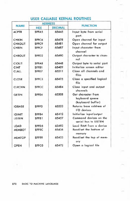
USER CALLABLE KERNAL ROUTINES
272 BASIC TO MACHINE LANGUAGE
ADDRESSNAME
HEX DECIMALFUNCTION
ACPTR $F.FA5 65445 Input. byte from serialport.
CHKIN $FFC6. 65478 Open channel for inputCHKOUT $FFC9 65481 Open channel for outputCHRIN $FFCF 65487 Input character from
channel
CHROUT $FFD2 65490 Output character to chan-nel
ClOUT $FFA8 65448 Output byte to serial portCINT $FF81 65409 Initialize screen' editorCLALL $FFE7 65511 Close all channels. and
files
CLOSE $FFC3 65475 Close a specified log ic'aIfile
CLRCHN $FFCC 65484- Close input and. output.channels
GETIN $FFE4 65508 Get character from
keyboard queue(keyboard buffer)
10BASE $FFF3 65523 Returns base address ofI/O devices
10lNIT $FF84 6541 2. Initialize input/outputLISTEN $FFB1 65457 Command devices on the
serial bus to LISTEN
LOAD $FFD5 65493 Load RAMfrom a deviceMEMBOT $FF9C 65436 Read/set the bottom of
memoryMEMTOP $FF99 65433 Read/set the top of mem-
oryOPEN $FFCO 65472 Open a logical file
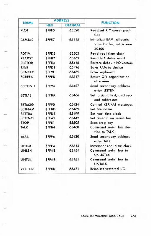
BASIC TO MACHINE LANGUAGE 273
NAMEADDRESS
FUNCTIONHEX DECIMAL
PLOT $FFFO 65520 Read/set X,Y cursor posi-tion
RAMTAS $FF87 65415 Initialize RAM, allocatetape buffer, set screen$0400
RDTIM $FFDE 65502 Read real time clockREADST $FFB7 65463 Read I/O status wordRESTOR $FF8A 65418 Restore default I/O vectorsSAVE $FFD8 65496 Save RAMto deviceSCNKEY $FF9F 65439 Scan keyboardSCREEN $FFED 65517 Return X,Y organization
of screenSECOND $FF93 65427 Send secondary address
after LISTENSETLFS $FFBA 65466 Set logical, first, and sec-
ond addressesSETMSG $FF90 65424 Control KERNALmessagesSETNAM $FFBD 65469 Set file nameSETTIM $FFDB 65499 Set real time clockSETTMO $FFA2 65442 Set timeout on serial busSTOP $FFE1 65505 Scan stop keyTALK $FFB4 65460 Command serial bus de-
vice to TALK
TKSA $FF96 65430 Send secondary addressafter TALK
UDTIM $FFEA 65514 Increment real time clockUNLSN $FFAE 65454 Command serial bus to
UNLISTENUNTLK $FFAB 65451 Command serial bus to
UNTALK
VECTOR $FF8D 65421 Read/set vectored I/O

B-1. Function Name: ACPTR
Purpose: Get data from the serial busCall address: $FFA5 (hex) 65445 (decimal)Communication registers: .APreparatory routines: TALK,TKSAError returns: See READSTStack requirements: 13Registers affected: .A, .X
Description: This is the routine to use when you want to get informa-tion from a device on the serial bus, like a disk. This routine gets a byteof data off the serial bus using full handshaking. The data is returned inthe accumulator. To prepare for this routine the TALKroutine must becalled first to command the device on the serial bus to send data
through the bus. If the input device needs a secondary command, itmust be sent by using the TKSA KERNAL routine before calling thisroutine. Errors are returned in the status word. The READSTroutine isused to read the status word.
How to Use:
0) Command a device on the serial bus to prepare to send data tothe Commodore 64. (Use the TALKand TKSA KERNALroutines.)
1) Call this routine (using JSR).2) Store or otherwise use the data.
EXAMPLE:
;GET A BYTE FROM THE BUSJSR ACPTR
STA DATA
274 BASIC TO MACHINE LANGUAGE
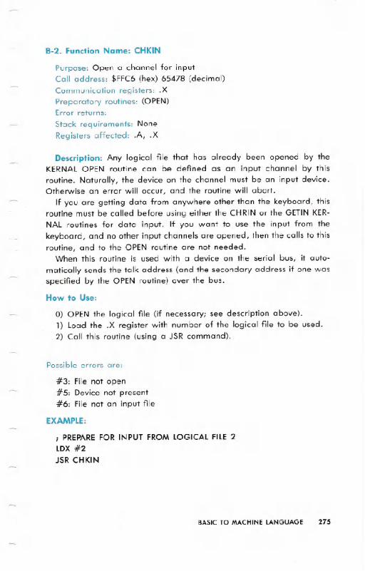
B-2. Function Name: CHKIN
Purpose: Open a channel for inputCall address: $FFC6 (hex) 65478 (decimal)Communication registers: .X
Preparatory routines: (OPEN)Error returns:
Stack requirements: None
Registers affected: .A, .X
Description: Any logical file that has already been opened by theKERNAL OPEN routine can be defined as an input channel by thisroutine. Naturally, the device on the channel must be an input device.Otherwise an error will occur, and the routine will abort.
If you are getting data from anywhere other than the keyboard, thisroutine must be called before using either the CHRIN or the GETIN KER-NAL routines for data input. If you want to use the input from thekeyboard, and no other input channels are opened, then the calls to thisroutine, and to the OPEN routine are not needed.
When this routine is used with a device on the serial bus, it auto-
matically sends the talk address (and the secondary address if one wasspecified by the OPEN routine) over the bus.
How to Use:
0) OPEN the logical file (if necessary; see description above).1) Load the .X register with number of the logical file to be used.2) Call this routine (using a JSR command).
Possible errors are:
#3: File not open#5: Device not present#6: File not an input file
EXAMPLE:
; PREPARE FOR INPUT FROM LOGICAL FILE 2LDX #2
JSR CHKIN
BASIC TO MACHINE LANGUAGE 275

B-3. Function Name: CHKOUT
Purpose: Open a channel for outputCall address: $FFC9 (hex) 65481 (decimal)Communication registers: .XPreparatory routines: (OPEN)Error returns: 0,3,5,7 (See READST)Stack requirements: 4+Registers affected: .A, .X
Description: Any logical file number that has been created by theKERNALroutine OPEN can be defined as an output channel. Of course,the device you intend opening a channel to must be an output device.Otherwise an error will occur, and the routine will be aborted.
This routine must be called before any data is sent to any outputdevice unless you want to use the Commodore 64 screen as your outputdevice. If screen output is desired, and there are no other output chan-nels already defined, then calls to this routine, and to the OPEN routineare not needed.
When used to open a channel to a device on the serial bus, thisroutine will automatically send the LISTENaddress specified by the OPENroutine (and a secondary address if there was one).
How to Use:
REMEMBER:this routine is NOT NEEDEDto send data to the screen.
0) Use the KERNALOPEN routine to specify a logical file number, aLISTENaddress, and a secondary address (if needed).
1) Load the .X register with the logical file number used in the openstatement.
2) Call this routine (by using the JSR instruction).
EXAMPLE:
LDX#3JSRCHKOUT
;DEFINE LOGICAL FILE 3 AS AN OUTPUT CHANNEL
Possible errors are:
#3: File not open#5: Device not present#7: Not an output file
276 BASIC TO MACHINE lANGUAGE
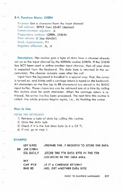
B-4. Function Name: CHRIN
Purpose: Get a character from the input channelCeill address: $FFCF (hex) 65487 (decimal)Communication registers: .APreparatory routines: (OPEN, CHKIN)Error returns: 0 (See READST)Stack requirements: 7+Registers affected: .A, .X
Description: This routine gets a byte of data from a channel alreadyset up as the input channel by the KERNALroutine <;:HKIN.If the CHKINhas NOT been used to defJneanother input channel, then all your ci"atais expected ,from the keyboard. The data byte is returned in'the ac-,cumulator. The channel remains open after the call.
Input from the keyboard is handled in a special way. First, the cursoris turned on, and blinks until a carriage return is typed on the keyboard.All characters on .the line (up to 88 characters) are stored in the BASICinput buffer. These characters can be retrieved one at a time by callingthis routine onc'e .for each character. When the carriage return is re-trieved, the entire ,line has been processed. The next time this routine iscalled, the whole process begins again, Le., by flashing the cursor.
How to Use:
FROM THE KEYBOARD
1) Retrieve a byte of data by calling this routine.2) Store the data byte.3) Check if it 'is the last data byte (is it a CR ?).4) If not, go to step 1.
EXAMPLE:
LDY$#00RD JSR CHRIN
STA DATA, Y
;PREPARE THE .Y REGISTER TO STORE THE DATA
;STORE THE YTH DATA BYTE IN THE YTH
;LOCATION IN THE DATA,AREA.INYCMP #CRBNE RD
;IS IT A CARRIAGE 'RETURN?
;NO, GET ANOTHER DATA BYTE
BASIC TO MACHINE LANGUAGE 277

EXAMPLE: -
JSR CHRIN
STA DATA
FROMOTHERDEVICES
0) Use the KERNAl OPEN and CHKIN routines.
1) Call this routine (using a JSR instruction).2) Store the data.
EXAMPLE:
JSR- CHRIN
STA DATA
B-5. Fundion Name: CHROUT
Purpose: Output a characterCall address: $FFD2 (hex) 65490 (decimal)Communication registers: .APreparatory routines: (CHKOUT,OPEN)Error returns: 0 (See READST)Stack requirements: 8+Registers affected: .A
Description: This routine outputs a character to an already openedchannel. Use the KERNAl OPEN and CHKOUT routines to set up theoutput channel before calling this routine. If this call is omitted, data issent to the default output device (number 3, the screen). The data byteto be output is loaded into the accumulator, and this routine is called.The data is then sent to the specified output device. The channel is leftopen after the call.
NOTE: Care must be taken when using this routine to send data to a specific serial
device since data will be sent to all open output channels -on the bus. Unless this isdesired, all open output channels on the serial bus other than the intended destinationchannel must be closed by a call- to the KERNALCLRCHN routine.
278 BASIC TO MACHINE LANGUAGE

How to Use:
0) Use the CHKOUT KERNAl routine if needed (see descriptionabove).
1) load the data to be output into the accumulator.2) Call:this routine.
EXAMPLE:
;DUPLICATETHEBASIC INSTRUCTION CMD 4,IA";lDX #4 ;lOGICAl FilE #4.JSR CHKOUT ;OPEN CHANNEL OUTLDA #'A.
JSR CHROUT _;SEND CHARACTER'
8-6. Function Name: ClOUT
Purpose: Transmit a byte over the serial bus
Call address:$FFA8 (hex) 65448 (decimal)
Communication registers: .A
Preparatory routines: LISTEN, [SECOND]Error returns: See READST
Stack requirements: 5
Registers affected: None
Description: This routine is used- to send information to devices on the
serial bus. A call to this routine will put a data byte onto the serial. bususing full serial handshaking. Before this routine is called, the LISTENKERNAl routine must be used to command a device on the serial bus to
get ready to receive data. (If a device needs a secondary address, itmust also be sent by using the SECOND KERNAl routine.) The ac-cumulator is loaded with a byte to handshake as data on the serial bus.
A device must be listening or the status word will return a timeout. This
routine always buffers one character. (The routine holds the previouscharacter to be sent back.) So when a call to the KERNAl UNLSN routineis made to end the data transmission, the buffered character is sent
with an End Or Identify (EOI) set. Then the UNlSN: command is sent tothe device.
BASIC TO MACHINE LANGUAGE 279
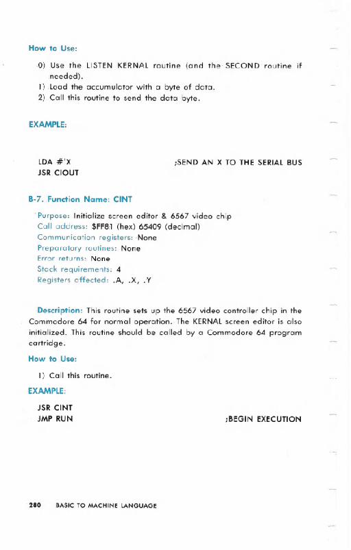
How to Use:
.0) Use the LISTEN KERNAL routine (and the' SECOND routine ifneeded).
1) Load the accumulator with a byte of data.2) Call this routine to send the data byte.
EXAMPLE:
lDA #'XJSR. ClOUT
;SEND AN X TO THE SERIALBUS
B-7. Function Name: CINT
. Purpose: Initialize screen editor & 6567 video chipCall address: $FFS:l (hex) 65409 (decimal)Communication registers: 'None
Preparatory routines: NoneError returns: None
Stack requirements: 4
Registers affected: .A, .X, .Y
Description: This routine sets up the 6567 video controller chip in theCommodore 64 for normal operation. The KERNALscreen editor is alsoinitialized. This routine should be called by a Commodore 64 programcartridge.
How to Use:
1) Call this routine.
EXAMPLE:
JSR CINTJMP RUN ;BEGIN EXECUTION
280 BASIC TO MACHINE LANGUAGE

B-8. Function Name: CLALL
Purpose: Close all fliesCall address: $FFE7 (hex) 65511 (decimal)Communication registers: NonePreparatory routines: NoneError returns: None
Stack requirements: 11Registers affected: .A, .X
Description: This routine closes all open flies. When this routine iscalled, the pointers into the open flle table are reset, closing all flies.Also, the CLRCHN routine is automatically called to reset the I/O chan-nels.
How to Use:
1} Call this routine.
EXAMPLE:
JSR CLALL iCLOSE ALL FILES AND SELECT DEFAULT I/O CHANNELS
JMP RUN iBEGIN EXECUTION
8-9. Function Name: CLOSE
Purpose: Close a-logical flleCall address: $FFC3 (hex) 65475 (decimal)Communication registers: .APreparatory routines: NoneError returns: 0,240 (See READST)Stack requirements: 2+Registers affected: .A, .X, .Y
Description: This routine is used to close a logical flle after all I/Ooperations have been completed on that flle. This routine is called afterthe accumulator is loaded with the logical file number to be closed (thesame number used when the flle was opened using the OPEN routine).
BASIC TO MACHINE LANGUAGE 281

How to Use:
1) Load the accumulator with the number of the logical file to bedosed.
2) Call this routine.
EXAMPLE:
;CLOSE 15LDA #15JSR CLOSE
B-10. Function Name: CLRCHN
Purpose: Clear I/O channels
Call address: $FFCC (hex) 65484 (decimal)
Communication registers: None
Preparatory routines: NoneError returns:
Stack requirements: 9
Registers affected: .A, .X
Description: This routine is called to clear all open channels and re-store the I/O channels to their original default values. It is usually calledafter opening other I/O channels (like a tape or disk drive) and usingthem for input/output operations. The default input device is 0(keyboard). The default output device is 3 (the Commodore 64 screen).
If one of the channels to be closed is to the serial port, an UNTALKsignal is sent first to clear the input channel or an UNLISTENis sent toclear the output channel. By not calling this routine (and leaving lis-tener(s) active on the serial bus) several devices can receive the samedata from the Commodore 64 at the same time. One way to take ad-vantage of this would be to command the printer to TALKand the disk toLISTEN.This would allow direct printing of a disk file.
This routine is automatically called when the KERNALCLALLroutine isexecuted.
How to Use:
1) Call this routine using the JSR instruction.
EXAMPLE:
JSR CLRCHN
282 BASIC TO MACHINE LANGUAGE
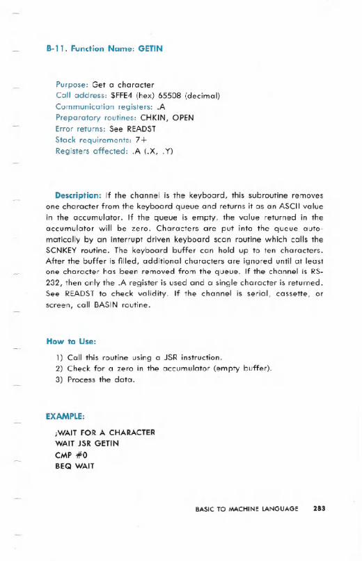
B-II. Function Name: GETIN
Purpose: Get a characterCall address: $FFE4(hex) 65508 (decimal)Communication registers: .APreparatory routines: CHKIN, OPENError returns: See READST
Stack requirements: 7+Registers affected: .A (.X, .Y)
Description: If the channel is the keyboard, this subroutine removesone character from the keyboard queue and returns it as an ASCII valuein the accumulator. If the queue is empty, the value returned in theaccumulator will be zero. Characters are put into the queue auto-matically by an interrupt driven keyboard scan routine which calls theSCNKEY routine. The keyboard buffer can hold up to ten characters.After the buffer is filled, additional characters are ignored until at leastone character has been removed from the queue. If the channel is RS-232, then only the .A register is used and a single character is returned.See READST to check validity. If the channel is serial, cassette; orscreen, call BASIN routine.
How to Use:
1) Call this routine using a JSR instruction.2) Check for a zero in the accumulator (empty buffer).3) Process the data.
EXAMPLE:
;WAIT FOR A CHARACTERWAIT JSR GETIN
CMP #0
BEQ WAIT
BASIC TO MACHINE LANGUAGE 283
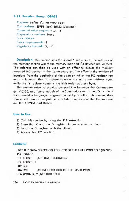
B-12. Function Name: IOBASE
Purpose: Deflne I/O memory pageCall address: $FFF3 (hex) 65523 (decimal)Communication registers: .X, .YPreparatory routines: NoneError returns:
Stack requirements: 2Registers affected: .X, .Y
Description: This routine sets the X and Y registers to the address ofthe memory section where the memory mapped I/O devices are located.This address can then be used with an offset to access the memorymapped I/O devices in the Commodore 64. The offset is the number oflocations from the beginning of the page on which the I/O register youwant is located. The .X register contains the low order address byte,while the .Y register contains the high order address byte.
This routine exists to provide compatibility between the Commodore64, VIC-20, and future models of the Commodore 64. If the I/O locationsfor a machine language program are set by a call to this routine, theyshould still remain compatible with future versions of the Commodore64, the KERNALand BASIC.
How to Use:
1) Call this routine by using the JSR instruction.2) Store the .X and the .Y registers in consecutive locations.3) Load the .Y register with the offset.4) Access that I/O location.
EXAMPLE:
; SETTHEDATADIRECTIONREGISTEROF THEUSERPORTTO 0 (INPUT)JSR 10BASESTXPOINT ;SET BASE REGISTERSSTYPOINT+lLDY#2LDA #0 ;OFFSETFOR DDROF THE USERPORTSTA (POINT), Y ;SETDDRTO 0
284 8ASIC TO MACHINE LANGUAGE

8-13. Function Name: lOlNIT
Purpose: Initialize r/o devicesCall Address: $FF84 (hex) 65412 (decimal)Communication registers: NonePreparatory routines: NoneError returns:Stack requirements: NoneRegisters affected: .A, ..X, .Y
Description: This routine initializes all input/output devices androutines. It is normally called as part of the initialization procedure of aCommodore- 64 program cartridge.
EXAMPLE:
JSR 10lNIT
B-14. Function Name: LISTEN
Purpose: Command a device on the serial bus to listenCall Address: $FFB-1 (hex) 65457 (decimai)
Communication registers: .A.
Preparatory routines: NoneError returns: See READST
Stack requirements: None
Registers affected: .A
Description: This routine will command a device on the serial bus toreceive data. The accumulator must be loaded with a device number
between 0 and 31 before calling the routine. LISTENwill OR the numberbit by bit to convert to a listen address, then transmits this data as acommand on the serial bus. The specified device will then go' into listenmode, and be ready to accept information.
How to Use:
1) Load the accumulator with the number of the device to commandto LISTEN.
2) Call this routine using the JSR instruction.
EXAMPLE:
;COMMAND DEVICE #8 TO LISTENLDA #8
JSR LISTEN
BASIC TO MACHINE LANGUAGE 285
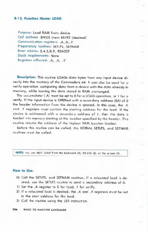
8-15. Fundion Name: LOAD
Purpose: load RAM from device
Call address: $FFD5 (hex) 65493 (decimal)Communication registers: .A, .X,. YPreparatory routines: SETlFS, SETNAMError returns: 0,4,5,8,9, READSTStack requirements: NoneRegisters affected: .A, .X, .Y
Description: This routine lOADs data bytes from any input device di-rectly into the memory of the Commodore 64. It can also be used for a
verify operation, comparing data from a device with the data already inmemory, while leaving the data stored in RAM unchanged.
The accumulator (.A) must beset to 0 for a LOADoperation, or 1 for averify. If the input device is OPENed with a secondary address (SA) of 0the header information from the device is ignored. In this case, the .Xand .Y.registers must contain the starting address for the load. If thedevice is addressed with .a secondary address of 1, then the data isloaded into memory starting at the location.specified by the header. Thisroutine returns the address of the highest RAM location loaded.
Before this routine can be called, the KERNAl SETlFS, and SETNAMroutines must be called.
:NOTE: You can NOT LOAD from the keyboard (0), RS-232 (2), or the screen (3).
How to Use:
.0) Call the SETlFS, and SETNAM routines. If a relocated load is de-
sired, use the SETlFS routine to send a secondary address of O.1) Set the .A register to 0 for load, 1 for verify.2) If a relocated load is desired, the .X and. Y registers must be set
to the start address for the load.
3) Call the routine using the JSR instruction.
286 BASIC TO MACHINE LANGUAGE

EXAMPLE:
iLOAD A FILE FROM TAPE
LDA #DEVICEl iSET DEVICE NUMBER
LDX #FILENO iSET LOGICAL FILE,NUMBER,
LDY CMDl' iSET SECONDARY ADDRESSJSR SETLFS
LDA #NAME1-NAME iLOAD .A WITH NUMBER OF
iCHARACTERS IN FILE NAME
iLOAD..X AND .Y WITH
iADDRESS OFiFILE NAME
NAMENAME 1
LDYJSRLDALDXLDYJSRSTXSTYJMP.BYT
LDX #<NAME
#>NAMESETNAM#0#$FF#$FFLOADVARTABVA RTA B + 1
START'FILE NAME'
B-16. Function Name: MEMBOT
iSET FLAG FOR A. LOADiAlTERNATE START
iEND OF LOAD'
Purpose: Set bottom of memoryCall address: $FF9C (hex) 65436 (decimal)
Communication registers: .X,.YPreparatory routines: NoneError returns: None
Stack requirements: NoneRegisters affected: .X, .Y
Description: This routine is used to set the bottom of the memory. Ifthe accumulator carry bit is set when this routine is called, a pointer tothe lowest byte of RAM is returned in the .X and .Y registers. On theunexpanded Commodore 64 the initial value of this pointer is $0800
(2048 in decimal). If the accumulator carry bit is clear (=0) when this
routine is called, the values of the .X and-. Y registers are transferred- to
the low and high bytes, respectively, of the pointer to the beginning ofRAM.
BASIC TO MACHINE LANGUAGE 287

How to Use:
TO READ THE BOTTOM OF RAM
1) Set the carry.-2) Call this routine.
TO SET THE BOTTOM OF MEMORY
1) Clear the carry.2) Call this routine.
EXAMPLE:
i MOVE BOTTOM OF MEMORY UP 1 PAGE
SECiREAD MEMORY BOTTOMJSR 'MEMBOTINY
CLC iSETMEMORY BOTTOM TO NEW VALUEJSR ,MEMBOT
8-17. Function Name: MEMTOP
Purpose: Set the top of RAMCall address: $FF99 (hex) 65433 (decimal)
Communication registers: .X, .YPreparatory routines: NoneError returns: None
Stack requirements: 2
Registers affected: .X, .Y
Description: This routine is used to set the top of RAM. When thisroutine is called with the carry bit of the accumulator set, the pointer tothe top of RAM.will be loaded into the .X and .Y registers. When thisroutine is called with the accumulator carry bit clear, the contents of the.X 'and .Y registers are loaded in the top .of :memory pointer, changingthe top of memory.
EXAMPLE:
iDEALLOCATE THE RS-232 BUFFERSEC
JSR 'MEMTOP ;READ TOP OF MEMORYDEX
CLC
JSR MEMTOP iSET NEW TOP OF'MEMORY
2BB BASIC TO MACHINE LANGUAGE

B-18.Function Name: OPEN
Purpose: Open a logical fileCall address: $FFCO (hex) 65472 (decimal)Communication registers: NonePreparatory routines: SETLFS,SETNAMError returns: 1,2,4,5,6,240, READSTStack requirements: NoneRegisters affected: .A, .X, .Y
Description: This routine is used to OPEN a logical file. Once the logi-cal file is set up, it can be used for input/output operations. Most of theI/O KERNALroutines call on this routine to create the logical files tooperate on. No arguments need to be set up to use this routine, but boththe SETLFSand SETNAM KERNALroutines must be called before usingthis routine.
How to Use:
0) Use the SETLFSroutine.1) Use the SETNAM routine.2) Call this routine.
EXAMPLE:
This is an implementation of the BASICstatement: OPEN 15,8,15,"1/0"
LDA #NAME2-NAMELDY#>NAMELDX#<NAMEJSR SETNAMLDA # 15LDX#8LDY#15JSR SETLFSJSR OPEN.BYT'I/O'
;LENGTH OF FILE NAME FOR SETLFS
;ADDRESS OF FILE NAME
NAMENAME2
BASICTO MACHINELANGUAGE 2B9

8-19. Fundion Name: PLOT
Purpose: Set cursor locationCall address: $FFFO (hex) 65520 (decimal)
Communication registers: .A, .X, .YPreparatory routines: NoneError returns: None
Stack requirements: 2Registers affected: .A, .X, .Y
Description: A call to this routine with the accumulator carry flag setloads the current position of the cursor on the screen (in X,Y coordinates)into the .Y and.X registers. Y is the column number of the cursor location(6-39), and X is the row number of the location of the cursor (0-24). Acall with the carry bit clear moves the cursor to X,Y as determined bythe .Y and .X registers.
How to Use:
READING CURSOR LOCATION
1) Set the carry flag.2) Call this routine.
3) Get the X and Y position from the .Y and .X registers, respectively.
SETTINGCURSOR LOCATION
1) Clear carry flag.2) Set the .Y and .X registers to the desired cursor location.3) Call this routine.
EXAMPLE:
; MOVE THE CURSOR TO ROW 10, COLUMN 5 (5,10)LDX#10LDY#5CLCJSR PLOT
290 BASIC TO MACHINE LANGUAGE

8-20. Function Name: RAMTAS
Purpose: Perform RAM testCall address: $FF87 (hex) 65415 (decimal)Communication registers: .A, .X, .YPreparatory routines: NoneError returns: None
Stack requirements: 2Registers affected: .A, .X, .Y
Description: This routine is used to test RAM and set the top andbottom of memory pointers accordingly. It also clears locations $0000 to$0101 and $0200 to $03FF. It also allocates the cassette buffer, and setsthe screen base to $0400. Normally, this routine is called as part of theinitialization process of a Commodore 64 program cartridge.
EXAMPLE:
JSR RAMTAS
B-21. Function Name: RDTIM
Purpose: Read system clockCall address: $FFDE(hex) 65502 (decimal)Communication registers: .A, .X, .YPreparatory routines: NoneError returns: None
Stack requirements: 2Registers affected: .A, .X, .Y
Description: This routine is used to read the system clock. The clock'sresolution is a 60th of a second. Three bytes are returned by the routine.The accumulator contains the most significant byte, the X index registercontains the next most significant byte, and the Y index register containsthe least significant byte.
EXAMPLE:
JSR RDTIMSTYTIME
STX TIME+ 1STA TIME+ 2
TIME *=*+3
BASIC TO MACHINE LANGUAGE 291

B-22. Function Name: READST
Purpose: Read status wordCall address: $FFB7 (hex) 65463 (decimal)
Communication registers: .APreparatory routines: NoneError returns: None
Stack requirements: 2Registers affected: .A
Description: This routine returns the current status of the I/O devices inthe accumulator. The routine is usually called after new communicationto an I/O device. The routine gives you information about device status,or errors that have occurred during the I/O operation.
The bits returned in the accumulator contain the following information:(see table below)
292 BASICTO MACHINE LANGUAGE
ST ST TAPEBIT NUMERIC CASSETTE SERIAURW VERIFY
POSITION VALUE READ + LOAD0 1 Time out
write1 2 Time out
read2 4 Short block Short block3 8 long block long block4 16 Unrecoverable Any
read error mismatch5 32 Checksum Checksum
error error6 64 End of file Earline7 -128 End of tape Device not End of
present tape

How to Use:
1) Call this routine.
2) Decode the information in the .A register as it refer-s to your pro-gram.
EXAMPLE:
;CHECK. FOR END OF FILE DURING READJSR READST
AND #6,4BNE EOF
;CHECK EOF BIT (EOF=END OF FILE)
;BRANCH ON EOF
8-23. Function Name: RESTOR
Purpose: Restore default system and interrupt vectorsCall address: $FF8A (hex) 65418 (decimal)Preparatory routines: NoneError returns: NoneStack requirements: 2
Registers affected: .A, .X, .Y
Description: This routine restores the default values of all system vec-
tors used in KERNAL and BASIC routines and interrupts. (See the Memory
Map for the default vector contents). The KERNAL VECTOR routine isused to read and alter individual- system vectors.
How to Use:
1) Call this routine.
EXAMPLE:
JSR RESTOR
8-24. Function Name: SAVE
Purpose: Save memory to a device
Call address: $FFD8 (hex) 65496 (decimal)
Communication registers: .A,.X,.Y
Preparatory routines: SETLFS, SETNAM
Error returns: 5,8,9, READSTStack requirements: None
Registers affected: .A, .X, .Y
BASICTO MACHINELANGUAGE 293

Description: This routine saves a section of memory. Memory is savedfrom an indirect address on page 0 specified by the accumulator to theaddress stored in the .X and .Y registers. It is then sent to a logical fileon an input/output device. The SETLFSand SETNAM routines must beused before calling this routine. However, a file name is not required toSAVEto device 1 (the Datassette™ recorder). Any attempt to save toother devices without using a file name results in an error.
"NOTE: Device 0 (the keyboard), device 2 (RS-232), and device 3 (the screen) cannotbe SAVEd to. If the attempt is made, an error occurs, and the SAVE is stopped.
How to Use:
0) Use the SETLFSroutine and the SETNAMroutine (unless a SAVEwithno file name is desired on "a save to the tape recorder").
1) Load two consecutive locations on page 0 with a pointer to thestart of your save (in standard 6502 low byte first, high byte nextformat).
2) Load the accumulator with the single byte page zero offset to thepointer.
3) Load the .X and .Y registers with the low byte and high byte re-spectively of the location of the end of the save.
4) Call this routine.
EXAMPLE:
LDA # 1JSR SETLFSLDA #0JSR SETNAMLDA PROGSTA TXTTAB
LDA PROG + 1
STA TXTTAB + 1
LDX VARTAB
LDY VARTAB+l
LDA #<TXTTAB
JSR SAVE
;DEVICE = 1:CASSETTE
;NO FILE NAME
;LOAD START ADDRESS OF SAVE
; (LOW BYTE)
; (HIGH BYTE)
;LOAD .X WITH LOW BYTE OF END OF SAVE
;LOAD .Y WITH HIGH BYTE
;LOAD ACCUMULATOR WITH PAGE 0 OFFSET
294 BASICTO MACHINELANGUAGE

B-25. Function Name: SCNKEY
Purpose: Scan the keyboardCall address:$FF9F (hex) 65439 (decimal)Communication registers: NonePreparatory routines: IOINITError returns: NoneStack requirements: 5Registers affected: .A, .X, .Y
Description: This routine scans the Commodore 64 keyboard andchecks for pressed keys. It is the same routine called by the interrupthandler. If a key is down, its ASCII value is placed in the keyboardqueue. This routine is called only if the normal IRQ interrupt is bypassed.
How to Use:
1) Call this routine.
EXAMPLE:
GET JSR SCNKEYJSR GETINCMP #0BEQ GETJSR CHROUT
iSCANKEYBOARD
iGET CHARACTER
ilS IT NULL?
iYES . . . SCAN AGAINiPRINT IT
8-26. Function Name: SCREEN
Purpose: Return screen formatCall address: $FFED(hex) 65517 (decimal)Communication registers: .X,. YPreparatory routines: NoneStack requirements: 2Registers affected: .X, .Y
Description: This routine returns the format of the screen, e.g., 40columns in .X and 25 lines in .Y. The routine can be used to determine
what machine a program is running on. This function has been im-.plemented on the Commodore 64 to help upward compatibility of yourprograms.
BASICTO MACHINELANGUAGE 295

How to Use:
1) Call this routine.
EXAMPLE:
JSR SCREEN
STX MAXCOL
STY MAXROW
8-27. Function Name: SECOND
Purpose: Send secondary address for LISTENCall address: $FF93 (hex) 65427 (decimal)Communication registers: .APreparatory routines: LISTENError returns: See READST
Stack requirements: 8Registers affected: .A
Description: This routine is used to send a secondary address to anI/O device after a call to the LISTEN routine is made, and the device is
commanded to LISTEN. The routine canNOT be used to send a second-
ary address after a call to the TALK routine.A secondary address is usually used to give setup information to a
device before I/O operations begin.
When a secondary address is to be sent to a device on the serial bus,the address must first be ORed with $60.
How to Use:
1) Load. the accumulator with the secondary address to be sent.2) Call this routine.
EXAMPLE:
;ADDRESS DEVICE #8 WITH COMMAND (SECONDARY ADDRESS) #15LDA #8
JSR LISTEN
LDA #15
JSR SECOND
296. BASIC TO MACHINE LANGUAGE
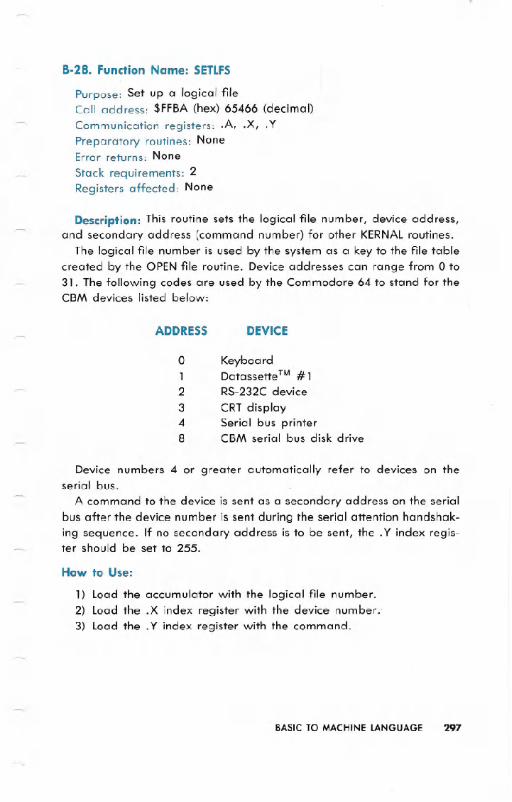
8-28. Function Name: SETLFS
Purpose: Set up a logical fileCall address: $FFBA (hex) 65466 (decimal)
Communication registers: .A, .X, .YPreparatory routines: NoneError returns: None
Stack requirements: 2Registers affected: None
Description: This routine sets the logical file number, device address,and secondary address (command number) for other KERNALroutines.
The logical file number is used by the system as a key to the file tablecreated by the OPEN file routine. Device addresses can range from 0 to31. The following codes are used by the Commodore 64 to stand for theCBM devices listed below:
ADDRESS DEVICE
o Keyboard1 Datassette™ #12 RS-232Cdevice3 CRTdisplay4 Serial bus printer8 CBM serial bus disk drive
Device numbers 4 or greater automatically refer to devices on theserial bus.
A command to the device is sent as a secondary address on the serialbus after the device number is sent during the serial attention handshak-ing sequence. If no secondary address is to be sent, the. Y index regis-ter should be set to 255.
How to Use:
1) Load the accumulator with the logical file number.2) Load the .X index register with the device number.'3) Load the .Y index register with the command.
BASIC TO MACHINE LANGUAGE 297

EXAMPLE:
FOR LOGICAL FILE32, DEVICE#4, AND NO COMMAND:LDA #32LDX #4LDY#255JSRSETLFS
8-29. Function Name: SETMSG
Purpose: Control system message outputCall address: $FF90 (hex) 65424 (decimal)Communication registers: .APreparatory routines: NoneError returns: NoneStack requirements: 2Registers affected: .A
Description: This routine controls the printing of error and control mes-sages by the KERNAL.Either print error messages or print control mes-sages can be selected by setting the accumulator when the routine iscalled. FILENOT FOUND is an example of an error message. PRESSPLAYON CASSETTEis an example of a control message.
Bits 6 and 7 of this value determine where the message will comefrom. If bit 7 is 1, one of the error messages from the KERNALis printed.If bit 6 is set, control messages are printed.
How to Use:
1) Set accumulator to desired value.
2) Call this routine.
EXAMPLE:
LDA #$40JSRSETMSG
LDA #$80JSRSETMSGLDA #0JSRSETMSG
jTURN ON CONTROL MESSAGES
jTURN ON ERROR MESSAGES
;TURN OFF ALL KERNAL MESSAGES
298 BASIC TO MACHINE LANGUAGE
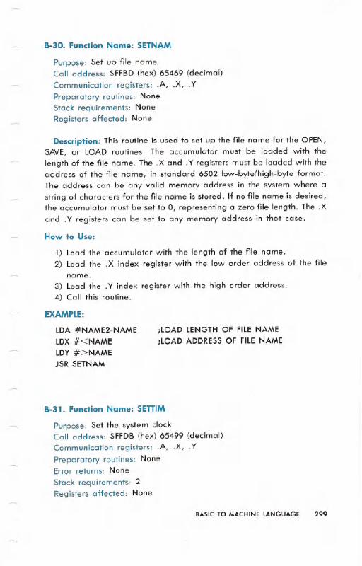
B-30. Function Name: SETNAM
Purpose: Set up file nameCall address: $FFBD (hex) 65469 (decimal)
Communication registers: .A, .X, .YPreparatory routines: NoneStack requirements: NoneRegisters affected: None
Description: This routine is used to set up the file name for tbe OPEN,SAVE, or LOAD routines. The accumulator must be loaded with thelength of the file name. The .X and .Y registers must be loaded with theaddress of the file name, in standard 6502 low-byte/high-byte format.The address can be any valid memory address in the system where astring of characters for the file name is stored. If no file name is desired,the accumulator must be set to 0, representing a zero file length. The .Xand .Y registers can be set to any memory address in that case.
How to Use:
1) Load the accumulator with the length of the file name.2) Load the .X index register with the low order address of the file
name.
3) Load the .Y index register with the high order address.4) Call this routine.
EXAMPLE:
LDA #NAME2-NAME
LDX #<NAME
LDY#>NAMEJSR SETNAM
;LOAD LENGTH OF FILE NAME
;LOAD ADDRESS OF FILE NAME
B-31. Function Name: SETTIM
Purpose: Set the system clockCall address: $FFDB (hex) 65499 (decimal)Communication registers: .A, .X, .Y
Preparatory routines: NoneError returns: None
Stack requirements: 2Registers affected: None
BASIC TO MACHINE LANGUAGE 299
Description: A system clock is maintained by an interrupt routine thatupdates the clock every 1/6Oth of a second (one "jiffy"). The clock isthree bytes long, which gives it the capability to count up to 5,184,000jiffies (24 hours). At that point the clock resets to zero. Before calling thisroutine to set the clock, the accumulator must contain the most
significant byte, the .X index register the next most significant byte, andthe .Y index register the least significant byte of the initial time setting(in jiffies).How to Use:
1) load the accumulator with the MSB of the 3-byte number to set theclock.
2) load the .X register with the next byte.3) load the .Y register with the lSB.4) Call this routine.
EXAMPLE:
;SET THE CLOCK TO 10 MINUTES = 3600 JIFFIES
lDA #0 ; MOST SIGNIFICANTLDX #>3600
LDY #<3600 ; LEAST SIGNIFICANTJSR SETTIM
8-32. Function Name: SETTMO
Purpose: Set IEEEbus card timeout flagCall address: $FFA2 (hex) 65442 (decimal)Communication registers: .APreparatory routines: NoneError returns: None
Stack requirements: 2Registers affected: None
NOTE: This routine is used ONLY with an IEEEadd-on card!
Description: This routine sets the timeout flag for the IEEEbus. Whenthe timeout flag is set, the Commodore 64 will wait for a device on theIEEE port for 64 milliseconds. If the device does not respond to theCommodore 64's Data Address Valid (DAV)signal within that time the
Commodore 64 will recognize an error condition and leave the hand-shake sequence. When this routine is called when the accumulator con-tains a 0 in bit 7, timeouts are enabled. A 1 in bit 7 will disable thetimeouts.
300 BASIC TO MACHINE LANGUAGE

NOTE: The Commodore 64 uses-the timeout feature to communicate that a disk:fileis
not found- on an -attempt to OPEN a ,file only with an IEEEcard.
How to Use:
TO SET THE TIMEOUTFLAGI) Set :bit 7 of the accumulator to ,0.2) Call this routine.
TO RESETTHE TIMEOUTFLAG
I) Set bit 7 of the accumulator tol.2) Call this routine.
EXAMPLE:
;DLSABLETIMEOUTLDA #0JSRSETTMO
'8-33. Function Name: STOP
Purpose: Check if III key is pressedCall address: $FFEI (hex) 65505 (decimal)
Communication registers: .APreparatory routines: NoneError returns: None
Stack requirements: NoneRegisters affected: .A, .X
Description: If .the 11I1I key on the keyboard was pressed duringa UDTIM call, this call returns the Z flag set. In addition; the channelswill be reset to default values. All other flags remain unchanged. If
the'. key is .not pressed then the accumulator will'contain a byterepresenting the.last row of the keyboard scan. The user can also checkfor certain other keys this way.
How to Use:
0) UDTIM should be called before this routine.I) Call this routine.2) Test for the z.ero flag.
BASICTO MACHINELANGUAGE 301
EXAMPLE:
JSR UDTIM ;SCAN FORSTOPJSRSTOPBNE *+5 ;KEYNOT DOWN
JMP READY ; = . . . STOP
B-34. Function Name: TALK
Purpose: Command a device on the serial bus to TALKCall address: $FFB4 (hex) 65460 (decimal)
Communication registers: .APreparatory routines: NoneError returns: See READST
Stack requirements: 8Registers affected: .A
Description: To use this routine the accumulator must first be loadedwith a device number between 0 and 31. When called, this routine thenORs bit by bit to convert this device number to a talk address. Then thisdata is transmitted as a command on the serial bus.
How to Use:
1) Load the accumulator with the. device number.2) Call this routine.
EXAMPLE:
;COMMAND DEVICE#4 TO TALK'LDA #4JSRTALK
8-35. Function Name: TKSA
Purpose: Send a secondary address to a device commanded to TALKCall addr.ess: $FF96 (hex) 65430 (decimal)
Communication registers: .APreparatory routines: TALKError returns: See READST
Stack requirements: 8Registers affected: .A
302 BASIC TO MACHINE LANGUAGE

Description: This routine transmits a secondary address on the serialbus for a TALKdevice. This routine must be called with a number be-tween 0 and 31 in the accumulator. The routine sends this number as a
secondary address command over the serial bus. This routine can onlybe called after a call to the TALKroutine. It will not work after a LISTEN.
How to Use:
0) Use the TALK routine.
1) Load the accumulator with the secondary address.2) Call this routine.
'EXAMPLE:
;TELLDEVICE#4 TO TALKWITH COMMAND #7LDA #4JSR TALKLDA #7JSR TALKSA
8-36. Function Name: UDTlM
Purpose: Update the system clockCall address: $FFEA (hex) 65514 (decimal)Communication registers: NonePreparatory routines: NoneError returns: None
Stack requirements: 2Registers affected: .A, .X
Description: This routine updates the system clock. Normally thisroutine is called by the normal KERNALinterrupt routine every 1/60th ofa second. If the user program processes its own interrupts this routinemust be called to update the time. In addition, the 11:I key routinemust be called, if the 11:I key is to remain functional.
How to Use:
1) Call this routine.
EXAMPLE:
JSR UDTIM
BASIC TO MACHINE LANGUAGE 303

8-37. Function Name: UNLSN
Purpose: Send an UNLISTENcommandCall address: $FFAE (hex) 65454 (decimal)Communication registers: NonePreparatory routines: None'Error returns: See READST
Stack requirements: 8Registers affected: .A
Description: This routine commands all devices on the' serial bus tostop receiving data from ,the Commodore 64 (Le., UNLISTEN).Callingthis routine results in an, UNLISTENcommand being transmitted on theserial bus. Only devices previously commanded to listen are affected.This routine is ,normally used after the Commodore 64 is finished sending,data to external devices. Sending the UNLISTENcommands the listening,devices to get off the, serial bus so it can be used for other purposes.
How to Use:
1) Call this routine.
EXAMPLE:
JSR UNLSN
8-38. Function Name: UNTLK
Purpose: Send an UNTALKcommand'Call address: $FFAB (hex) 65451 (decimal)Communication registers: NonePreparatory routines: NoneError returns: See READST
Stack requirements: 8Registers affected: .A
DesCI'iption: This routine transmits an UNTALKcommand on the serialbus. All devices previously set to TALKwill stop sending data when thiscommand .is received.
How to' Use:
1) Call this routine.
EXAMPLE:
JSR UNTALK
304' BASIC TO. MACHINE LANGUAGE,

8-39. Function Name: VECTOR
Purpose: Manage RAM vectorsCall address: $FF8D (hex) 65421 (decimal)Communication registers: .X,.YPreparatory routines: NoneError returns: None
Stack requirements: 2Registers affected: .A, .X, .Y
Description: This routine manages all system vector jump addressesstored in RAM. Calling this routine with the the accumulator carry bit setstores the current contents of the RAM vectors in a list pointed to by the.X and .Y registers. When this routine is called with the carry clar, theuser list pointed to by the .X and. Y registers is transferred to the systemRAM vectors. The RAM vectors are listed in the memory map.
NOTE: This routine requires caution in its use. The best way to use it is to first read the
entire vector contents into the user area, alter the desired vectors, and then copy thecontents bock to the system vectors.
How to Use:
READ THE SYSTEM RAM VECTORS
1) Set the carry.2) Set the .X and .y registers to the address to put the vectors.3) Call this routine.
LOAD THE SYSTEMRAM VECTORS
1) Clear the carry bit.2) Set the .X and .Y registers to the address of the vector list in RAM
that must be loaded.3) Call this routine.
BASIC TO MACHINE LANGUAGE 305

EXAMPLE:
;CHANGE THE INPUT ROUTINES TO NEW SYSTEMLDX#<USERLDY#>USERSEC
JSR VECTOR ;READ OLD VECTORSLDA #<MYINP ;CHANGE INPUTSTA USER+l0LDA #>MYINPSTA USER+ 11LDX#<USERLDY#>USERCLC
JSR VECTOR ;ALTERSYSTEM
USER * =* +26
ERROR CODES
The following is a list of error messages which can occur when usingthe KERNALroutines. If an error occurs during a KERNALroutine, thecarry bit of the accumulator is set, and the number of the error messageis returned in the accumulator.
NOTE: Some KERNAll/O routines do not use these codes for error messages. Instead,
errors are identified using the KERNAl READST routine.
306 BASIC TO MACHINE LANGUAGE
NUMBER MEANING
0 Routine terminated by the" key1 Too many open files2 File already open3 File not open4 File not found5 Device not present6 File is not an input file7 File is not an output file8 File name is missing9 Illegal device number
240 Top-of-memory change RS-232 buffer allocation/deallocation
USING MACHINE LANGUAGE FROM BASIC
There are several methods of using BASIC and machine language on
the Commodore 64, including special statements as part of CBM BASICas well as key locations in the machine. There are five main ways to use
machine language routines from BASIC on the Commodore 64. Theyare:
1) The BASIC SYS statement
2) The BASIC USR function
3) Changing one of the RAM I/O vectors
4) Changing one of the RAM interrupt vectors
5) Changing the CHRGET routine
1) The BASIC statement SYS X causes a JUMP to a machine languagesubroutine located at address X. The routine must end with an RTS
(ReTurn from Subroutine) instruction. This will transfer control backto BASIC.
Parameters are generally passed between the machine lan-
guage routine and,the BASIC program using the BASIC PEEK and
POKE statements, and their machine language equivalents.The SYS command is the most useful method of combining
BASIC with machine language. PEEKs and POKEs make multipleparameter passing easy. There can be many SYS statements in aprogram, each to a different (or even the same) machine lan-
guage routine.
2) The BASIC function USR(X) transfers control to the machine lan-
guage subroutine located at the address stored in locations 785
and 786. (The address is stored in standard low-byte/high-bytefprmat.) The value X is evaluated and passed to the machine lan-
guage subroutine through floating point accumulator #1, located
beginning at address $61 (see memory map for more details). Avalue may be returned back to the BASIC program by placing it inthe floating point accumulator. The machine language routine mustend with an RTS instruction to return to BASIC.
Thisstatement is different from the SYS,because you have TOsetup an indirect vector. Also different is the format through which
the variable is passed (floating point format). The indirect vectormust be changed if more than one machine language routine isused.
BASIC TO MACHINE LANGUAGE 307
3) Any of the input/output or BASIC internal routines accessed throughthe vector table located on page 3 (see ADDRESSING MODES,ZERO PAGE) can be replaced, or amended by user code. Each2-byte vector consists of a low byte and a high byte address whichis used by the operating system.
The KERNALVECTOR routine is the most reliable way to changeany of the vectors, but a single vector can be changed by POKEs.A new vector will point to a user prepared routine which is meantto replace or augment the standard system routine. When the ap-propriate BASIC command is executed, the user routine will beexecuted. If after executing the user routine, it is necessary to exe-cute the normal system routine, the user program must JMP (JuMP)to the address formerly contained in the vector. If not, the routinemust end with a RTS to transfer control back to BASIC.
4) The HARDWAREINTERRUPT(IRQ) VECTORcan be changed. Every1/60th of a second, the operating system transfers control to theroutine specified by this vector. The KERNALnormally uses this fortiming, keyboard scanning, etc. If this technique is used, youshould always transfer control to the normal IRQ handling routine,unless the replacement routine is prepared to handle the CIA chip.(REMEMBERto end the routine with an RTI(ReTurnfrom Interrupt)if the CIA is handled by the routine).
This method is useful for tasks which must happen concurrentlywith a BASIC program, but has the drawback of being moredifficult.
NOTE: ALWAYS DISABLE INTERRUPTS BEFORE CHANGING THIS VECTORI
5) The CHRGETroutine is used by BASICto get each character/token.This makes it simple to add new BASIC commands. Naturally,each new command must be executed by a user written machinelanguage subroutine. A common way to use this method is tospecify a character (@ for example) which will occur before any ofthe new commands. The new CHRGETroutine will search for thespecial character. If none is present, control is passed to the nor-mal BASIC CHRGETroutine. If the special character is present, thenew command is interpreted and executed by your machine lan-guage program. This minimizes the extra execution time added bythe need to search for additional commands. This technique isoften called a wedge.
308 BASIC TO MACHINE LANGUAGE

WHERE TO -PUT MACHINE LANGUAGE ROUTINES
The best place for machine langua.ge routines on the Commodore 64is from $COOO-$CFFF, assuming the routines are smaller than 4K byteslong. This section of memory is not disturbed by BASIC.
If for some reason _it's not possible or desirable to put the machinelanguage routine at $COOO,for instance if the routine is larger than 4Kbytes, it then becomes _necessary to reserve an area at the top of mem-ory from BASIC for the routine. The top of memory is normally$9FFF.The top of memory can be changed through the KERNAL routineMEMTOP, or by the following BASIC statements:
10 POKE51,L:POKE52,H:POKE55,L:POKE56,H:CLR
Where Hand L are the high and low portions, respectively, of the newtop of memory. For -example, to reserve the area from $9000 to $9FFFfor machine language, use the following:
10 POKE51,0:POKE52, 144:POKE55,0:POKE56, 144:CLR
HOW TO ENTER MACHINE LANGUAGE
There are 3 common methods to add the machine language pro-
grams to a BASIC program. They are:
1) DATA STATEMENTS:
By READing DATAstatements, and POKEing the values into memory atthe start of the program, machine language routines can be added. Thisis the easiest method. No special methods are needed to save the twoparts of the _program, and it is fairly easy to debug. The drawbacksinclude taking up more memory space, and the wait while the programis POKEd in. Therefore, this method is better-for smaller routines.
EXAMPLE:
10 RESTORE: FORX=1 T09:READA: POKE12* 4096 + X,A: NEXT
BASIC PROGRAM
1000 DATA 161, 1,204,204,204,204,204,204,96
- BASIC TO MACHINE LANGUAGE 309

2) MACHINE LANGUAGE MONITOR (64MON):
This program allows you to enter a program in either HEX or SYM-BOLICcodes, and save the portion of memory the program is in. Advan-tages of this method include easier entry of the machine languageroutines, debugging aids, and a much faster means of saving and load-ing. The drawback to this method is that it generally requires the BASICprogram to load the machine language. routine from tape or disk whenit is started. (For more details on 64MON see the machine' languagesection.)
EXAMPLE:
The following is an example of a BASIC program using a machinelanguage routine. prepared by 64MON. The routine is stored on tape:
10lF FLAG=l THEN 2015 FLAG=l:LOAD "MACHINE LANGUAGE ROUTINE NAME",l,l20
REST OF BASIC PROGRAM
3) EDITOR/ASSEMBLER PACKAGE:
Advantages are similar to using a machine language monitor, butprograms are even easier to enter. Disadvantages are also similar to theuse of a machine language monitor.
COMMODORE 64 MEMORY MAP
310 BASIC TO MACHINE LANGUAGE
LABELHEX DECIMAL
DESCRIPTIONADDRESS LOCATION
D6510 0000 0 6510 On-Chip Data-Direction Register
R6510 0001 1 6510 On-Chip 8-BitInput/Output Register
0002 2 Unused
ADRAYl 0003-0004 3-4 Jump Vector: ConvertFloating-Integer
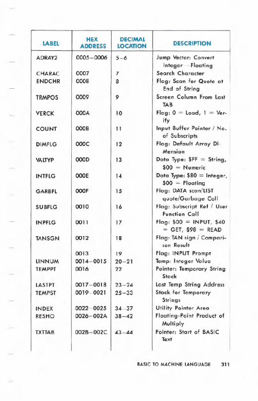
BASICTO MACHINELANGUAGE 311
LABELHEX DECIMAL
DESCRIPTIONADDRESS LOCATION
ADRAY2 0005-0006 5-6 Jump Vector: ConvertInteger-Floating
CHARAC 0007 7 Search CharacterENDCHR 0008 8 Flag: Scan for Quote at
End of StringTRMPOS 0009 9 Screen Column From Last
TAB
VERCK OOOA 10 Flag: 0 = Load, 1 = Ver-
ifyCOUNT OOOB 11 Input Buffer Pointer / No.
of SubscriptsDIMFlG OOOC 12 Flag: Default Array DI-
Mension
VALTYP OOOD 13 Data Type: $FF = String,$00 = Numeric
INTFlG OOOE 14 Data Type: $80 = Integer,$00 = Floating
GARBFL OOOF 15 Flag: DATAscan/liSTquote/Garbage Coli
SUBFlG 0010 16 Flag: Subscript Ref / UserFunction Call
INPFlG 0011 17 Flag: $00 = INPUT,$40= GET, $98 = READ
TANSGN 0012 18 Flag: TAN sign / Compari-son Result
0013 19 Flag: INPUT PromptlINNUM 0014-0015 20- 21 Temp: Integer ValueTEMPPT 0016 22 Pointer: Temporary String
Stack
LASTPT 0017 -0018 23-24 Last Temp String AddressTEMPST 0019-0021 25-33 Stack for Temporary
StringsINDEX 0022-0025 34-37 Utility Pointer AreaRESHO 0026-002A 38-42 Floating-Point Product of
MultiplyTXTTAB 002B-002C 43-44 Pointer: Start of BASIC
Text

312 BASIC TO MACHINE LANGUAGE
LABELHEX DECIMAL
DESCRIPTIONADDRESS LOCATION
VARTAB 002D-002E 45-46 Pointer: Start of BASICVariables
ARYTAB 002F-0030 47 -48 Pointer: Start of BASIC
ArraysSTREND 0031...,.0032 49-50 Pointer: End of BASIC Ar-
rays (+ 1)FRETOP 0033-0034 5.1-52 Pointer: Bottom of String
.StorageFRESPC 0035-0036 53-54 Utility String PointerMEMSIZ 0037 -0038 55-56 Pointer: Highest Address
Used by BASICCURLIN 0039-003A 57-58 Current BASIC Line
NumberOLDLIN 003B-003C 59-60 Previous BASIC Line
NumberOLDTXT 003D-003E 61-62 Pointer: BASIC Statement
for CO NTDATLIN 003F-0040 63-64 Current DATALine
NumberDATPTR 0041-0042 65-66 Pointer: Current DATA
Item AddressINPPTR 0043 -0044 67-68 Vector: INPUT RoutineVARNAM 0045-0046 69-70 Current BASIC Variable
NameVARPNT 0047 -0048 71-72 Pointer: Current BASIC
Variable Data
FORPNT 0049-004A 73-74 Pointer: Index Variablefor FOR/NEXT
004B-0060 75-96 Temp Pointer / Data AreaFACEXP 0061 97 Floating-Point Accumu-
lator # 1: ExponentFACHO 0062-0065 98-101 Floating Accum. #.1:
MantissaFACSGN 0066 102 Floating Accum. #1: SignSGNFLG 0067 103 Pointer.: Series Evaluation
Constant

BASICTO MACHINELANGUAGE 313
LABELHEX DECIMAL
DESCRIPTIONADDRESS LOCATION
BITS 0068 104 Floating Accum. # 1:Overflow Digit
ARGEXP 0069 105 Floating-Point Accumu-lator #2: Exponent
ARGHO 006A-006D 106-109 Floating Accum. #2:Mantissa
ARGSGN 006E 110 Floating Accum. #2: SignARISGN 006F 111 Sign Comparison Result:
Accum. #1 vs #2FACOV 0070 112 Floating Accum. #1.
low-Order (Rounding)FBUFPT 0071-0072 113-114 Pointer: Cassette BufferCHRGET 0073-008A 115-138 Subroutine: Get Next Byte
of BASIC Text
CHRGOT 0079 121 Entry to Get Same Byte ofText Again
TXTPTR 007A-007B 122-123 Pointer: Current Byte ofBASIC Text
RNDX 008B-008F 139-143 Floating RND FunctionSeed Value
STATUS 0090 144 Kernal I/O StatusWord: ST
STKEY 0091 145 Flag: STOP key / RVS keySVXT 0092 146 Timing Constant for TapeVERCK 0093 147 Flag: 0 = load, 1 = Ver-
ifyC3PO 0094 148 Flag: Serial Bus-Output
Char. Buffered
BSOUR 0095 149 Buffered Character forSerial Bus
SYNO 0096 150 Cassette Sync No.0097 151 Temp Data Area
LDTND 0098 152 No. of Open Files / Indexto File Table
DFlTN 0099 153 Default Input Device (0)DFlTO 009A 154 Default Output (CMD)
Device (3)
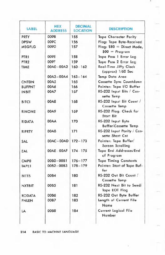
314 BASIC TO MACHINE LANGUAGE
LABELHEX DECIMAL
DESCRIPTIONADDRESS LOCATION
PRTY 009B 155 Tape Character ParityDPSW 009C 156 Flag: Tape Byte-ReceivedMSGFLG 009D 157 Flag: $80 = Direct Mode,
$00 = ProgramPTRl 009E 158 Tape Pass 1 Error LogPTR2 009F 159 Tape Pass 2 Error LogTIME 00AO-00A2 160-162 Real-Time Jiffy Clock
(approx) 1/60 Sec00A3-00A4 163-164 Temp Data Area
CNTDN 00A5 165 Cassette Sync CountdownBUFPNT 00A6 166 Pointer: Tape I/O BufferINBIT 00A7 167 RS-232 Input Bits / Cas-
sette TempBITCI 00A8 168 RS-232 Input Bit Count /
Cassette TempRINONE 00A9 169 RS-232 Flag: Check for
Start Bit
RIDATA OOAA 170 RS-232 Input ByteBuffer/Cassette Temp
RIPRTY OOAB 171 RS-232 Input Parity / Cas-sette Short Cnt
SAL OOAC-OOAD 172-173 Pointer: Tape Buffer/Screen Scrolling
EAL OOAE-OOAF 174-175 Tape End Addresses/Endof Program
CMPO OOBO-OOB 1 176-177 Tape Timing ConstantsTAPEl 00B2-00B3 178-179 Pointer: Start of Tape Buf-
fer
BITTS 00B4 180 RS-232 Out Bit Count /
Cassette TempNXTBIT 00B5 181 RS-232 Next Bit to Send/
Tape EOT FlagRODATA 00B6 182 RS-232 Out Byte BufferFNLEN 00B7 183 Length of Current File
. NameLA 00B8 184 Current Logical File
Number

BASIC TO MACHINE LANGUAGE 315
LABELHEX DECIMAL
DESCRIPTIONADDRESS LOCATION
SA 00B9 185 Current Secondary Ad-dress
FA OOBA 186 Current Device NumberFNADR OOBB-OOBC 187 - 188 Pointer: Current File
NameROPRTY OOBD 189 RS-232 Out Parity / Cas-
sette TempFSBLK OOBE 190 Cassette Read/Write Block
CountMYCH OOBF 191 Serial Word BufferCASl OOCO 192 Tape Motor 'InterlockSTAL 00CI-00C2 193-194 I/O Start AddressMEMUSS 00C3-00C4 195-196 Tape Load TempsLSTX 00C5 197 Current Key Pressed:
CHR${n) 0 = No KeyNDX 00C6 198 No. of Chars. in
Keyboard Buffer(Queue)
RVS 00C7 199 Flag: Print ReverseChars.-l =Yes, O=NoUsed
INDX 00C8 200 Pointer: End of LogicalLine for INPUT
LXSP 00C9-00CA 201-202 Cursor X-VPos. at Start ofINPUT
SFDX OOCB 203 Flag: Print Shifted Chars.BLNSW OOCC 204 - Cursor Blink enable: 0 =
Flash CursorBLNCT OOCD 205 Timer: Countdown to
Toggle CursorGDBLN OOCE 206 Character Under CursorBLNON OOCF 207 Flag: Last Cursor Blink
On/OffCRSW OODO 208 Flag: INPUT or GET from
KeyboardPNT 00DI-00D2 209-210 Pointer: Current Screen
Line Address

316 BASIC TO MACHINE LANGUAGE
LABELHEX DECIMAL
DESCRIPTIONADDRESS LOCATION
PNTR 00D3 211 Cursor Column on CurrentLine
QTSW 00D4 212 Flag: Editor in QuoteMode, $00 = NO
LNMX 00D5 213 Physical Screen Linelength
TBLX 00D6 214 Current Cursor PhysicalLine Number
00D7 215 Temp Data AreaINSRT 00D8 216 Flag: Insert Mode, >0 =
# INSTslDTBl 00D9-00F2 217-242 Screen Line Link Table /
Editor TempsUSER 00F3-00F4 243-244 Pointer: Current Screen
Color RAM loc.KEYTAB 00F5-00F6 245-246 Vector: Keyboard Decode
TableRIBUF 00F7-00F8 247-248 RS-232 Input Buffer
PointerROBUF 00F9-00FA 249-250 RS-232 Output Buffer
PointerFREKZP OOFB-OOFE 251-254 Free O-Page Space for
User ProgramsBASZPT OOFF 255 BASIC Temp Data Area
0100-0lFF 256-511 Micro-Processor SystemStack Area
0100-010A 256-266 Floating to String WorkArea
BAD 0100-013E 256-318 Tape Input Error logBUF 0200-0258 512-600 System INPUT BufferLAT 0259-0262 601-610 KERNAl Table: Active log-
ical File No's.FAT 0263-026C 611-620 KERNAl Table: Device No.
- for Each File
SAT 026D-0276 621-630 KERNAl Table: SecondAddress Each File
KEYD 0277 -0280 631-640 Keyboard Buffer Queue(FIFO)

BASICTO MACHINELANGUAGE 317
LABELHEX DECIMAL
DESCRIPTIONADDRESS LOCATION.
MEMSTR 0281-0282 . 641-642 Pointer: Bottom of Memoryfor' O.S.
MEMSIZ 0283-0284 643-644 Pointer: Top of Memory forO.S.
TIMOUT 0285 645 Flag: Kernal Variable forIEEE Timeout
COLOR 0286 646 Current Character ColorCode
GDCOl 0287 647 Background Color UnderCursor
HIBASE 0288 648 Top of Screen Memory(Page)
XMAX 0289 649 Size of Keyboard BufferRPTFLG 028A 650 Flag: REPEATKey. Used,
$80 = RepeatKOUNT 028B' 651 Repeat Speed CO.unterDELAY 028C 652 Repeat. Delay CounterSHFLAG 028D 653 Flag: Keyb'rd SHIFT Key/
CTRLKey/C= KeyLSTSHF 028E 654 Last Keyboard Shift Pat-
ternKEYLOG 028F-0290 655-656 Vector: Keyboard Table
SetupMODE 0291 657 Flag: $OO=Disable SHIFT
Keys, $80 = EnableSHIFT Keys
AUTODN 0292 658 Flag: Auto Scroll Down, 0= ON.
M51CTR 0293 659 RS-232: 6551' Control
Register ImageM51CDR 0294 660 RS-232: 6551. Command
Register ImageM51AJB 0295-0296 661-662 RS-232 Non-Standard BPS
(Time/2-100) USARSSTAT 0297 663 RS-232: 6551 Status Regis-
ter ImageBITNUM 0298 664 RS-232 Number of Bits
Left to Send

318 8ASIC TO MACHINE LANGUAGE
LABELHEX 'DECIMAL
DESCRIPTIONADDRESS LOCATJON
BAUDOF 0299-029A 665-666 RS-232 Baud Rate: Full Bit
Time (s)RIDBE 029B 667 RS-232 Index to End of
Input BufferRIDBS 029C 668 RS-232 Start of Input Buf-
fer (Page)RODBS 029D 669 RS-232 Start of Output
Buffer (Page)RODBE 029E 670 RS-232 Index to End of
Output BufferIRQTMP 029F-02AO 671-672 Holds IRQ Vector During
Tape I/OENABL 02A1 673 RS-232 Enables
02A2 674 TOD Sense During Cas-sette I/O
02A3 675 Temp Storage For CassetteRead
02A4 .676 Temp D11RQ Indicator ForCassette Read
02A5 677 Temp For Line Index02A6 678 PALINTSCFlag, 0=
NTSC, 1= PAL02A7-02FF 679-767 Unused
IERROR 0300-0301 768-769 Vector: Print BASIC Error
MessageIMAIN 0302-0303 770-771 Vector: BASIC Warm Start
ICRNCH 0304-0305 772-773 Vector: Tokenize BASICText
IQPLOP 0306-0307 774-775 Vector: BASIC Text LIST
IGONE 0308-0309 776-777 Vector: BASIC Char. Dis-
patchIEVAL 030A-030B 778-779 Vector: BASIC Token
Evaluation
SAREG 030C 780 Storage for 6502 .A Reg-ister
SXREG 030D 781 Storage for 6502 .X Regis-ter
I

BASIC TO MACHINE LANGUAGE 319
LABELHEX . DECIMAL
DESCRIPTIONADDRESS LOCATION
SYREG 030E 782 Storage for 6502 .Y Regis-ter
SPREG 030F 783 Storage for 6502 .SPRegister
USRPOK 0310 784 USR Function Jump Instr(4C)
USRADD 0311-0312 785-786 USR Address Low Byte/High Byte
0313 787 UnusedCINV 0314-0315 788-789 Vector: Hardware IRQ
InterruptCBINV 0316-0317 790-791 Vector: BRKInstr. InterruptNMINV 0318-0319 792 -793 Vector: Non-Maskable
InterruptIOPEN 031A-031 B 794-795 KERNALOPEN Routine
VectorIClOSE 031 C-031 D 796-797 KERNAl CLOSE Routine
VectorICHKIN 031 E-031 F 798-799 KERNAl CHKIN Routine
VectorICKOUT 0320-0321 800-801 KERNAl CHKOUT Routine
VectorIClRCH 0322-0323 802 - 803 KERNAl ClRCHN Routine
VectorIBASIN 0324-0325 804-805 KERNAl CHRIN Routine
VectorIBSOUT 0326-0327 806-807 KERNAl CHROUT Routine
VectorISTOP 0328-0329 808-809 KERNAl STOP Routine
VectorIGETIN 032A-032B 810-811 KERNAl GETIN Routine
VectorICLAll 032C-032D 812-813 KERNAl CLAll Routine
VectorUSRCMD 032E-032F 814-815 User-Defined VectorIlOAD 0330-0331 816-817 KERNAl lOAD Routine
Vector
,
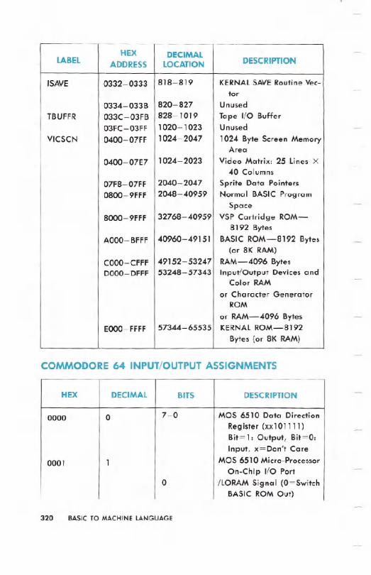
COMMODORE 64 INPUT/OUTPUT ASSIGNMENTS
320 BASIC TO MACHINE LANGUAGE
HEX DECIMALLABEL ADDRESS LOCATION DESCRIPTION
ISAVE 0332-0333 818-819 KERNALSAVERoutine Vec-tor
0334-033B 820-827 UnusedTBUFFR 033C-03FB 828-1019 Tape I/O Buffer
03FC-03FF 1020- 1023 Unused
VICSCN 0400-07FF 1024- 2047 1024 Byte Screen MemoryArea
0400-07E7 1024-2023 Video Matrix: 25 Lines X40 Columns
07F8-07FF 2040-2047 Sprite Data Pointers0800-9FFF 2048-40959 .Normal BASIC Program
Space8000-9FFF 32768:....40959 VSP Cartridge ROM-
8192 BytesAOOO- BFFF 40960-49151 BASIC ROM-8192 Bytes
(or 8K RAM)COOO-CFFF 49152-53247 RAM-4096 BytesDOOO-DFFF 53248-57343 Input/Output Devices and
Color RAMor Character Generator
ROM
or RAM-4096 Bytes. EOOO-FFFF 57344-65535 KERNALROM-8192
Bytes (or 8K RAM)
HEX DECIMAL BITS DESCRIPTION
0000 0 7-0 MOS 6510 Data Direction
Register (xx101111)Bit= 1: Output, Bit=O:Input, x=Don't Care
0001 1 MOS 6510 Micro-Processor
On-Chip I/O Port0 /LORAM Signal (O=Switch
BASIC ROM Out)

BASIC TO MACHINE LANGUAGE 321
HEX DECIMAL BITS DESCRIPTION
1 /HIRAM Signal (O=SwitchKernal ROM Out)
2 /CHAREN Signal(O=Switch Char. ROMIn)
3 Cassette Data Output Line4 Cassette Switch Sense
1 = Switch Closed
5 Cassette Motor Control0= ON, 1 = OFF
6-7 UndefinedDOOO-D02E 53248-54271 MOS 6566 VIDEO INTER-
FACE CONTROLLER(VIC)
DOOO 53248 Sprite 0 X PosDOOI 53249 Sprite 0 Y PosD002 53250 Sprite 1 X PosDOO3 53251 Sprite 1 Y PosD004 53252 Sprite 2 X PosD005 53253 Sprite 2 Y PosD006 53254 Sprite 3 X PosD007 53255 Sprite 3 Y PosD008 53256 Sprite 4 X PosD009 53257 Sprite 4 Y PosDOOA 53258 Sprite 5 X PosDOOB 53259 Sprite 5 Y PosDOOC 53260 Sprite 6 X PosDOOD 53261 Sprite 6 Y PosDOOE 53262 Sprite 7 X PosDOOF 53263 Sprite 7 Y PosDOlO 53264 Sprites 0-7 X Pos (msb of
X coord.)DOn 53265 VIC Control Register
7 Raster Compare: (Bit 8)See 53266
6-
Extended Color TextMode: 1 = Enable
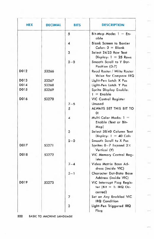
322 BASICTOMACHINELANGUAGE
HEX DECIMAL BITS DESCRIPTION
5 Bit-Map Mode: 1 = En-able
4 Blank Screen to BorderColor: 0 = Blank
3 Select 24/25 Row Text
Display: 1 = 25 Rows2-0 Smooth Scroll to Y Dot-
Position (0-7)D012 53266 Read Raster / Write Raster
Value for Compare IRQD013 53267 Light-Pen latch X PosD014 53268 Light-Pen latch Y PosD015 53269 Sprite Display Enable:
1 = EnableD016 53270 VIC Control Register
7-6 Unused
5 ALWAYSSET THIS BIT TO01
4 Multi-Color Mode: 1 =Enable (Text or Bit-Map)
3 Select 38/40 Column Text
Display: 1 = 40 CoIs2-0 Smooth Scroll to X Pos
D017 53271 Sprites 0-7 Expand 2XVertical (Y)
D018 53272 VIC Memory Control Reg-ister
7-4 Video Matrix Base Ad-dress (inside VIe)
3-1 Character Dot-Data BaseAddress (inside VIe)
D019 53273 VIC Interrupt Flag Regis-ter (Bit = 1: IRQ Oc-
curred)7 Set on Any Enabled VIC
IRQ Condition3 Light-Pen Triggered IRQ
Flag

BASIC TO MACHINE LANGUAGE 323
HEX DECIMAL BITS DESCRIPTION
2 Sprite to Sprite CollisionIRQ Flag
1 Sprite to BackgroundCollision IRQ Flag
. 0 Raster Compare IRQ FlagD01A 53274 IRQ Mask Register: 1 =
Interrupt EnabledD01B 53275 Sprite to Background
Display Priority: 1 =Sprite
D01C 53276 Sprites 0-7 Multi-ColorMode Select: 1 =M.C.M.
D01D 53277 Sprites 0-7 Expand 2XHorizontal (X)
DOlE 53278 Sprite to Sprite CollisionDetect
D01F 53279 Sprite to BackgroundCollision Detect
D020 53280 Border ColorD021 53281 Background Color 0D022 53282 Background Cplor 1D023 53283 Background Color 2D024 53284 Background Color 3D025 53285 Sprite Multi-Color Regis-
ter 0D026 53286 Sprite Multi-Color Regis-
ter 1D027 53287 Sprite 0 ColorD028 53288 Sprite 1 ColorD029 53289 Sprite 2 ColorD02A 53290 Sprite 3 ColorD02B 53291 Sprite 4 ColorD02C 53292 Sprite 5 ColorD02D 53293 Sprite 6 ColorD02E 53294 Sprite 7 ColorD400-D7FF 54272-55295 MOS 6581 SOUND
INTERFACEDEVICE
(SID)
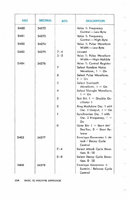
324 BASIC TO MACHINE LANGUAGE
HEX DECIMAL BITS DESCRIPTION
D400 54272 Voice 1: FrequencyControl - Low-Byte
D401 54273 Voice 1: FrequencyControl-High-Byte
D402 54274 Voice 1: Pulse Waveform
Width -low-ByteD403 54275 7-4 Unused
3-0 Voice 1: Pulse Waveform
Width-High-NybbleD404 54276 Voice 1: Control Register
7 Select Random NoiseWaveform, 1 = On
6 Select Pulse Waveform,1 = On
5 Select SawtoothWaveform, 1 = On
4 Select Triangle Waveform,1 = On
3 Test Bit: 1 = Disable Os-cilIator 1
2 Ring Modulate Osc. 1 withOsc. 3 Output, 1 = On
1 Synchronize Osc. 1 withOsc. 3 Frequency, 1 =On
0 Gate Bit: 1 = Start Aftl
DeclSus, 0 = Start Re-lease
D405 54277 Envelope Generator 1: At-tack I Decay CycleControl
7-4 Select Attack Cycle Dura-tion: 0-15
3-0 Select Decay Cycle Dura-tion: 0- 15
D406 54278 Envelope Generator 1:Sustain I Release CycleControl

BASICTO MACHINELANGUAGE 325
HEX DECIMAL BITS DESCRIPTION
7-4 Select Sustain Cycle Du-ration: 0-15
3-0 Select Release Cycle Du-ration: 0- 15
D407 54279 Voice 2: FrequencyControl- Low-Byte
D408 54280 Voice 2: FrequencyControl-High-Byte
D409 54281 Voice 2: Pulse Waveform
Width-low-ByteD40A 54282 7-4 Unused
3-0 Voice 2: Pulse Waveform
Width-High-NybbleD40B 54283 Voice 2: Control Register
7 Select Random NoiseWaveform, 1 = On
6 Select Pulse Waveform,1 = On
5 Select SawtoothWaveform, 1 = On
4 Select TriangleWaveform, '1 = On
3 Test Bit: 1 = Disable Os-cillator 2
2 Ring Modulate Osc. 2 withOsc. 1 Output, 1 = On
1 Synchronize Osc. 2 withOsc. 1 Frequency, 1 =On
0 Gate Bit: 1 = Start AttlDec/Sus, 0 = Start Re-lease
D40C 54284 Envelope Generator 2: At-tack I Decay CycleControl
7-4 Select Attack Cycle Dura-tion: 0- 15
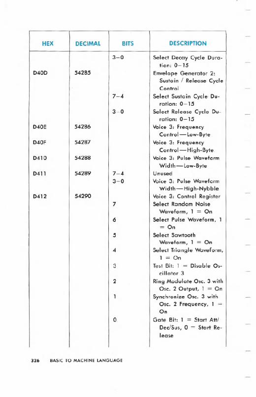
326 BASIC TO MACHINE LANGUAGE
HEX DECIMAL BITS DESCRIPTION
3-0 Select Decay Cycle Dura-tion: 0-15
D40D 54285 Envelope Generator 2:Sustain / Release CycleControl
7-4 Select Sustain Cycle Du-ration: 0- 15
3-0 Select Release Cycle Du-ration: 0- 15
D40E 54286 Voice 3: FrequencyControl-low-Byte
D40F 54287. Voice 3: FrequencyControl-High-Byte.
D410 54288. Voice 3: Pulse Waveform
Width - low-ByteD411 54289 7-4 Unused
3-0 Voice 3: Pulse WaveformWidth - High-Nybble
D412 54290 Voice 3: Control Register7 Select Random Noise
Waveform, 1 = On6 Select Pulse Waveform, 1
= On5 Select Sawtooth
Waveform, 1 = On4 Select Triangle Waveform,
1 = On3 Test Bit: 1 = Disable Os-
cillator 32 Ring ModulateOsc. 3 with
Osc. 2 Output, 1 = On1 Synchronize Ose. 3 with
Osc. 2 Frequency, 1 =On
0 Gate Bit: 1 = Start Att/DeclSus, 0 = Start Re-lease

BASIC TO MACHINE LANGUAGE 327 .
HEX DECIMAL BITS DESCRIPTION
D413 54291 Envelope Generator 3: At-tack / Decay CycleControl
7-4 Select Attack Cycle Dura-tion: 0- 15
3-0 Select Decay Cycle Dura-tion: 0-15
D414 54292 Envelope Generator 3:Sustain / Release CycleControl
7-4 Select Sustain Cycle Du-ration: 0-15
3-0 Select Release Cycle Du-ration: 0-15
D415 54293 Filter Cutoff Frequency:Low-Nybble (Bits 2-0)
D416 54294 Filter Cutoff Frequency:High-Byte
D417 54295 Filter Resonance Control /
Voice Input Control7-4 Select Filter Resonance:
0-153 Filter External Input: 1 =
Yes, 0 = No2 Filter Voice 3 Output: 1 =
Yes, 0 = No1 Filter Voice 2 Output: 1 =
Yes, 0 = No0 Filter Voice 1 Output: 1 =
Yes, 0 = NoD418 54296 Select Filter Mode and
Volume7 Cut-Off Voice3 Output: 1
= Off, 0 = On
6 Select Filter High-PassMode: 1 = On
5 Select Filter Band-PassMode: 1 = On

328 BASIC TO MACHINE LANGUAGE
HEX DECIMAL BITS DESCRIPTION
4 Select Filter low-PassMode: 1 = On
3-0 Select Output Volume:0-15
D419 54297 Analog/Digital Converter:Game Paddle 1 (0-255)
D41A 54298 Analog/Digital Converter:Game Paddle 2 (0-255)
D41B 54299 Oscillator 3 RandomNumber Generator
D41C 54230 Envelope Generator 3Output
D500-D7FF 54528-55295 SID IMAGESD800-DBFF 55296-56319 Color RAM(Nybbles)DCOO-DCFF 56320.-56575 MOS 6526 Complex
Interface Adapter (CIA)#1
DCOO 56320 Data Port A (Keyboard,Joystick, Paddles,light-Pen)
7-0 Write Keyboard ColumnValues for KeyboardScan
7-6 Read Paddles on Port A /B (01 = Port A, 10 =Port B)
4 Joystick A fire Button: 1 =Fire
3-2 Paddle Fire Buttons3-0 Joystick A Direction
(0- 15)DCOl 56321 Data Port B (Keyboard,
Joystick, Paddles):Game Port 1

BASIC TO MACHINE LANGUAGE 329
HEX DECIMAL BITS DESCRIPTION
7-0 Read Keyboard Row
Values for Keyboard
Scan7 Timer B: Toggle/Pulse
Output6 Timer A: Toggle/Pulse
Output4 Joystick 1 Fire Button: 1 =
Fire
3-2 Paddle Fire Buttons
3-0 Joystick 1 Direction
DC02 56322 Data Direction
Register-Port A
(56320)DC03 56323 Data Direction
Register-Port B
(56321)DC04 56324 Timer A: Low-ByteDC05 56325 Timer A: High-ByteDC06 56326 Timer B: Low-ByteDC07 56327
Timer B: High-ByteDC08 56328 Time-of-Day Clock: 1/10
SecondsDC09 56329 Time-of-Day Clock: Sec-
ondsDCOA 56330 Time-of-Day Clock: Min-
utesDCOB 56331 Time-of-Day Clock: Hours
+ AM/PM Flag (Bit7)DCOC 56332 Synchronous Serial I/O
Data BufferDCOD 56333
CIA Interrupt Control
Register (Read IRQs/
Write Mask)
7 IRQ Flag (1 = IRQ Oc-
curred) / Set-Clear Flag
4 FLAG1 IRQ (Cassette Read
/ Serial Bus SRQ Input)
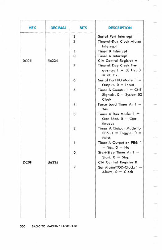
330 BASIC TO MACHINE LANGUAGE
HEX DECIMAL BITS DESCRIPTION
3 Serial Port Interrupt2 Time-of-Day Clock Alarm
Interrupt1 Timer B Interrupt0 Timer A Interrupt
DCOE 56334 CIA Control Register A7 Time-of-Day Clock Fre-
quency: 1 = 50 Hz, 0= 60 Hz
6 Serial Port I/O Mode: 1 =Output, 0 = Input
5 Timer A Counts: 1 = CNT
Signals, 0 = System 02Clock
4 Force Load Timer A: 1 =Yes
3 Timer A Run Mode: 1 =One-Shot, 0 = Con-tinuous
2 Timer A Output Mode toPB6: 1 = Toggle, 0 =Pulse
1 Timer A Output on PB6: 1= Yes, 0 = No
0 Start/Stop Timer A: 1 =Start, 0 = Stop
DCOF 56335 CIA Control Register B7 Set Alarm/TOD-Clock: 1 =
Alarm, 0 = Clock
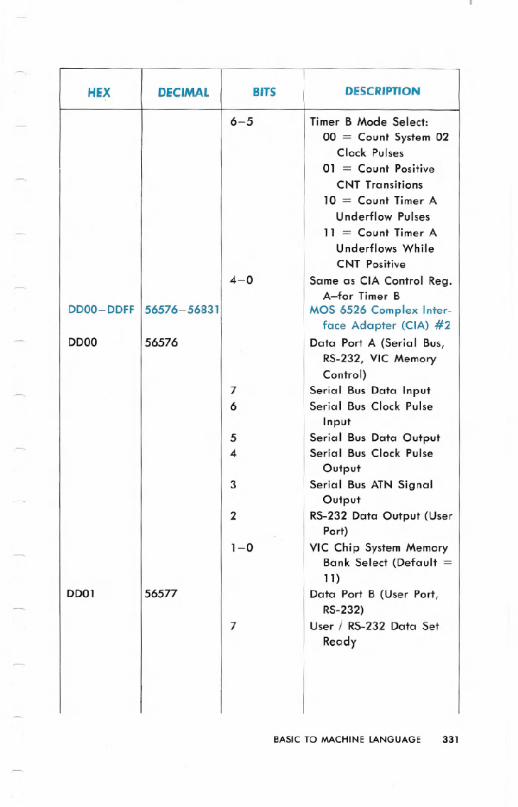
BASIC TO MACHINE LANGUAGE 331
HEX DECIMAL BITS DESCRIPTION
6-5 Timer B Mode Select:
00 = Count System 02Clock Pulses
01 = Count Positive
CNT Transitions
10 = Count Timer AUnderflow Pulses
11 = Count Timer AUnderflows WhileCNT Positive
4-0 Same as CIA Control Reg.A-for Timer B
DDOO-DDFF 56576-56831 MOS 6526 Complex Inter-face Adapter (CIA) #2
DDOO 56576 Data Port A (Serial Bus,
RS-232, VIC MemoryControl)
7 Serial Bus Data Input6 Serial Bus Clock Pulse
Input5 Serial Bus Data Output4 Serial Bus Clock Pulse
Output3 Serial Bus ATN Signal
Output2 RS-232 Data Output (User
Port)1-0 VIC Chip System Memory
Bank Select (Default =11)
DD01 56577 Data Port B (User Port,
RS-232)7 User / RS-232 Data Set
Ready
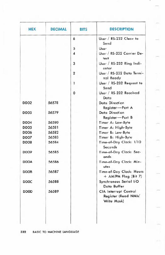
332 BASIC TO MACHINE LANGUAGE
HEX DECIMAL BITS DESCRIPTION
6 User / RS-232 Clear toSend
5 User4 User / RS-232 Carrier De-
tect3 User / RS-232 Ring Indi-
cator2 User / RS-232 Data Termi-
nal Ready1 User / RS-232 Request to
Send0 User / RS-232 Received
DataDD02 56578 Data Direction
Register-Port ADD03 56579 Data Direction
Register-Port BDD04 56580 Timer A: Low-ByteDD05 56581 Timer A: High-Byte0006 56582 Timer B: Low-ByteDD07 56583 Timer B: High-ByteD008 56584 Time-of-Day Clock: 1/10
SecondsDD09 56585 Time-of-Day Clock: Sec-
onds
DDOA 56586 Time-of-Day Clock: Min-utes
DOOB 56587 Time-of-Day Clock: Hours+ AM!PM Flag (Bit 7)
DDOC 56588 Synchronous Serial I/OData Buffer
DDOD 56589 CIA Interrupt ControlRegister (Read NMls/Write Mask)

BASIC TO MACHINE LANGUAGE 333
HEX DECIMAL BITS DESCRIPTION
7 NMI Flag (1 = NMI Oc-curred) / Set-Clear Flag
4 FLAG1 NMI (UserlRS-232Received Data Input)
3 Serial Port Interrupt1 Timer B Interrupt0 Timer A Interrupt
DDOE 56590 CIA Control Register A7 Time-of-Day Clock Fre-
.quency: 1 = 50 Hz, 0= 60 Hz
6 Serial Port I/O Mode: 1 =Output, 0 = Input
5 Timer A .Counts: 1 = CNTSignals, 0 = System 02Clock
4 Force Load Timer A: 1 =Yes
3 Timer A Run Mode: 1 =One-Shot, 0 = Con-tinuous
2 Timer A Output .Mode toPB6: 1 = Toggle, 0 =Pulse
1 -TimerA Output on PB6: 1= Yes, 0 = No
0 Start/Stop Timer A: 1 =Start, 0 = Stop
DDOF 56591 CIA Control Register B7 Set Alarm/TOD-Clock: 1 =
Alarm, 0 = Clock
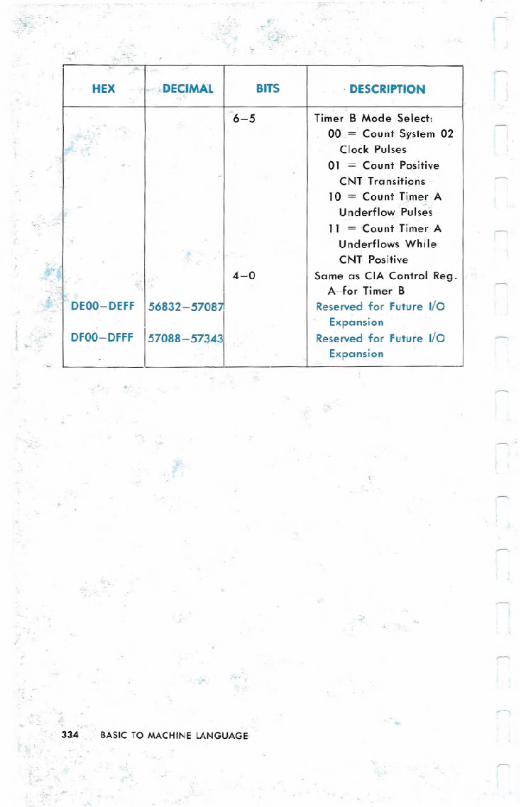
-....
334 BASIC TO MACHINE LANGUAGE
..
HEX - DECIMAL BITS . DESCRIPTION
6-5 Tiiner B Mode Select:00 = Count System02
Clock Pulses01 = Count Positive
CNT Transitions10 = Count Ti.merA
Underflow Pulses11 = Count Timer A. Underflows While
CNT Positive
4-0 Same as CIA Control Reg.A-for Timer B
. DEOO-DEFF 56832-57081 Reserved for Future I/O
ExpansionDFOO-DFFF 57088-57343 Reserved for Future I/O
Expansion


