CC1N7547en 20.04.2016 Building Technologies Division 7 547 LMV26.300... AGM60.1... Basic unit with integrated fuel-air ratio control for forced draft burners LMV26.300... Dual fuel switch unit AGM60.1... The LMV26... burner management system is a microprocessor-based burner control with matching system components for the control and supervision of forced draft burners of medium to high capacity. For using of dual fuel with 2 fuel actuators, AGM60... dual fuel switch unit is required. The LMV26… / AGM60... and this Data Sheet are intended for use by OEMs which integrate the actuators in their products!
Transcript
CC1N7547en 20.04.2016
Building Technologies Division
7547
LMV26.300... AGM60.1...
Basic unit with integrated fuel-air ratio control for forced draft burners
LMV26.300...
Dual fuel switch unit AGM60.1...
The LMV26... burner management system is a microprocessor-based burner control with matching system components for the control and supervision of forced draft burners of medium to high capacity. For using of dual fuel with 2 fuel actuators, AGM60... dual fuel switch unit is required. The LMV26… / AGM60... and this Data Sheet are intended for use by OEMs which integrate the actuators in their products!
2/25
Building Technologies Division CC1N7547en 20.04.2016
Use
Microprocessor-controlled basic unit for single-fuel burners of any capacity for intermittent operation, electronic air-fuel ratio control, maximum 2 actuators, integrated gas valve proving and VSD control. The system components (display and operating unit, actuators) are connected to operating on a single fuel directly to the LMV26... basic unit. All safety-related digital inputs and outputs of the system are monitored by contact feedback network. - Gas burner controls to EN 298 - For forced draft gas burners to EN 676 - For oil burners with fan to EN 267 The AGM60… dual fuel switch unit connected to the LMV26... serves for changeover of valve control or for feedback signals and the actuators from the 2 types of fuel. For intermittent operation in connection with the LMV26... / AGM60..., the ionization probe or the QRA..., QRB... or QRC… optical flame detector can be used. Continuous operation is possible only when using an ionization probe and without AGM60...
Features
The following components are integrated in the basic unit of the LMV26…: Burner management system complete with valve proving system Electronic fuel / air ratio control system for a maximum of 2 actuators SQM3... or
SQN1... Control of VSD for air fan Modbus interface BCI for connection a display or PC Unit parameter adjustable either via display or PC software ACS410
Notes
Warning! All safety, warning and technical notes given in the Basic Documentation of the LMV26… (P7547) also apply to this document!
For Europe
3/25
Building Technologies Division CC1N7547en 20.04.2016
Standards and certificates
Applied directives: Low-voltage directive 2014/35/EC Directive for gas-fired appliances 2009/142/EC Directive for pressure devices 97/23/EC and
*) The compliance with EMC emission requirements must be checked after the burner management
system is installed in equipment
Compliance with the regulations of the applied directives is verified by the adherence to the following standards / regulations: Automatic burner control systems for burners and appliances
burning gaseous or liquid fuels DIN EN 298
Safety and control devices for gas burners and gas burning appliances - Valve proving systems for automatic shut-off valves
DIN EN 1643
Gas/air ratio controls for gas burners and gas burning appliances - Part 2: Electronic types
DIN EN 12067-2
Safety and control devices for gas burners and gas burning appliances
DIN EN 13611
Safety and control devices for gas burners and gas-burning appliances - Particular requirements Part 1: Automatic and semi-automatic valves
ISO 23552-1
Automatic electrical controls for household and similar use Part 2-5: Particular requirements for automatic electrical burner control systems
DIN EN 60730-2-5
The relevant valid edition of the standards can be found in the declaration of conformity!
Note on DIN EN 60335-2-102 Household and similar electrical appliances - Safety - Part 2-102: Particular requirements for gas, oil and solid-fuel burning appliances having electrical connections. The electrical connections of the LMV2 comply with the requirements of EN 60335-2-102.
EAC Conformity mark (Eurasian Conformity mark)
ISO 9001:2008 ISO 14001:2004 OHSAS 18001:2007
4/25
Building Technologies Division CC1N7547en 20.04.2016
Life cycle
The burner management system LMV26... has a designed lifetime* of 250,000 burner startup cycles which, under normal operating conditions in heating mode, correspond to approx. 10 years of usage (starting from the production date given on the type field). The AGM60... dual fuel switch unit has a designed lifetime* of 5,000 burner startup cycles which, under normal operating conditions in heating mode, correspond to approx. 10 years of usage (starting from the production date given on the type field). This lifetime is based on the endurance tests specified in standard EN 298. A summary of the conditions has been published by the European Control Manufacturers Association (Afecor) (www.afecor.org). The designed lifetime is based on use of the LMV26... / AGM60... according to the manufacturer’s Data Sheet and Basic Documentation. When reaching the designed lifetime in terms of the number of burner startup cycles or time of usage, the LMV26... / AGM60... must be replaced by authorized personnel. * The designed lifetime is not the warranty time specified in the Terms of Delivery
The diagram shows the full scope of functions of the LMV26… system. The actual functions are to be determined based on the respective execution / configuration!
LMV26...
AGM60...
General
5/25
Building Technologies Division CC1N7547en 20.04.2016
Ordering
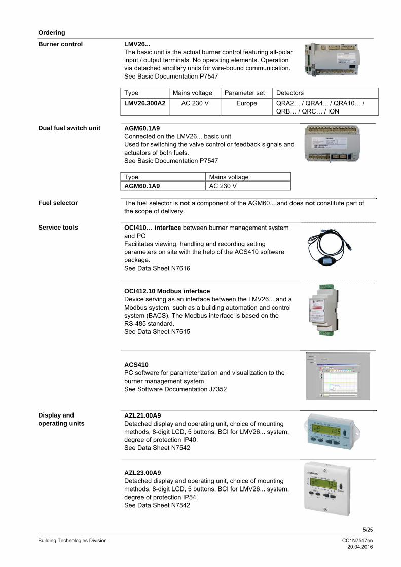
LMV26... The basic unit is the actual burner control featuring all-polar input / output terminals. No operating elements. Operation via detached ancillary units for wire-bound communication. See Basic Documentation P7547 Type Mains voltage Parameter set Detectors
LMV26.300A2 AC 230 V Europe QRA2… / QRA4... / QRA10… / QRB… / QRC… / ION
AGM60.1A9 Connected on the LMV26... basic unit. Used for switching the valve control or feedback signals and actuators of both fuels. See Basic Documentation P7547 Type Mains voltage
AGM60.1A9 AC 230 V The fuel selector is not a component of the AGM60... and does not constitute part of the scope of delivery. OCI410… interface between burner management system and PC Facilitates viewing, handling and recording setting parameters on site with the help of the ACS410 software package. See Data Sheet N7616
OCI412.10 Modbus interface Device serving as an interface between the LMV26... and a Modbus system, such as a building automation and control system (BACS). The Modbus interface is based on the RS-485 standard. See Data Sheet N7615
ACS410 PC software for parameterization and visualization to the burner management system. See Software Documentation J7352
AZL21.00A9 Detached display and operating unit, choice of mounting methods, 8-digit LCD, 5 buttons, BCI for LMV26... system, degree of protection IP40. See Data Sheet N7542
AZL23.00A9 Detached display and operating unit, choice of mounting methods, 8-digit LCD, 5 buttons, BCI for LMV26... system, degree of protection IP54. See Data Sheet N7542
Burner control
Dual fuel switch unit
Fuel selector
Service tools
Display and operating units
6/25
Building Technologies Division CC1N7547en 20.04.2016
Ordering (cont´d)
QRA2… Flame detector for use with Siemens burner controls, for the supervision of gas flames and yellow- / blue-burning oil flames as well as ignition spark checking. Plastic housing, metalized to prevent static charging caused by the air flow from the fan. For direct mounting on the burner. The detectors can be supplied with or without securing flange and clamp. See Data Sheet N7712
QRA4... Flame detector for use with Siemens burner controls, for the supervision of gas flames and yellow- or blue-burning oil flames as well as for ignition spark proving. See Data Sheet N7711
QRA10… Flame detector for use with Siemens burner controls, for the supervision of gas flames and yellow- / blue-burning oil flames as well as ignition spark checking. Die-cast aluminium housing with a 1 in. mounting coupling and connection facility for cooling air. The housing of this detector has a bayonet fitting which allows it to be secured either directly to the 1 in. mounting coupling or to the AGG06. The 1 in. mounting coupling can be screwed to a viewing tube or to the AGG07. The Pg cable gland can be removed and replaced, if some other detector cable shall be used. See Data Sheet N7712
QRB… Photo resistive flame detector for use with Siemens burner controls, for the supervision of oil flames in the visible light spectrum. Especially suited for use with burner controls for small capacity burners in intermittent operation. See Data Sheet N7714
QRC… Blue-flame detector for use with Siemens burner controls, for the supervision of blue- or yellow-burning oil or gas flames. Especially suited for use with burner controls for small capacity burners in intermittent operation. See Data Sheet N7716
Frontal illumination:
Lateral illumination:
Flame detectors
7/25
Building Technologies Division CC1N7547en 20.04.2016
Ordering (cont´d)
SQM33.4… Rated torque 1.2 Nm (0.8 Nm holding torque when dead), running time 5 s, stepper motor, front mounting, D-type drive shaft. See Data Sheet N7813
SQM33.5… Rated torque 3 Nm (2.6 Nm holding torque when dead), running time 5 s, stepper motor, front mounting, D-type drive shaft. See Data Sheet N7813 SQM33.7… Rated torque 10 Nm (6 Nm holding torque when dead), running time 17 s, stepper motor, front mounting, D-type drive shaft. See Data Sheet N7813
SQN1… Rated torque 1 Nm (0.2 Nm holding torque when dead), running time 5 s, stepper motor, front mounting, D-type drive shaft. See Data Sheet N7803
Actuators
8/25
Building Technologies Division CC1N7547en 20.04.2016
Ordering (cont´d)
AGG3.131 Complete connector set RAST2.5 / RAST3.5 / RAST5 for gas / oil applications, single pack. See Object List C7541 (74 319 0637 0)
Example: X5-02
AGG3.132 Complete connector set RAST2.5 / RAST3.5 / RAST5 for gas- / oil applications, pack of 10. See Object List C7541 (74 319 0637 0) AGG9… Single connectors Packing unit 200 in total
Example X5-03
Type Type of connector Terminal AGG9.203 RAST5 X3-02 AGG9.204 RAST5 X3-03 AGG9.206 RAST5 X8-04 AGG9.209 RAST5 X10-06 AGG9.217 RAST5 X75 AGG9.303 RAST5 X3-05 AGG9.304 RAST5 X4-02 AGG9.306 RAST5 X5-01 AGG9.307 RAST5 X5-02 AGG9.309 RAST5 X6-03 AGG9.310 RAST5 X7-01 AGG9.311 RAST5 X7-02 AGG9.313 RAST5 X9-04 AGG9.403 RAST5 X5-03 AGG9.406 RAST5 X8-02 AGG9.501 RAST5 X3-04 AGG9.504 RAST5 X10-05 AGG9.853 RAST3,5 X64 and X74 AGG5.310 Accessories set speed control, for burner management systems, composed of sensor disk 50, sensor and mounting set. See Mounting instructions M7550.1 (74 319 9322 0)
Connector sets
Accessories
9/25
Building Technologies Division CC1N7547en 20.04.2016
Ordering (cont´d)
AGV50.100 Signal cable for AZL2..., with RJ11 connector, length 1 m, pack of 10
AGV50.300 Signal cable for AZL2..., with RJ11 connector, length 3 m, pack of 10
AGV61.100 Connecting cable between LMV26... and AGM60..., cable length 0.5 m See Basic Documentation P7547
Cables
10/25
Building Technologies Division CC1N7547en 20.04.2016
Ordering (cont´d)
VKP Proportional controlling element for mounting between threaded flanges in gas trains. Refer to Data Sheet N7646
ASK33.1 Larger mounting plate required to replace existing mounting plate. Required for mounting the actuators SQM4 or SQM33. Refer to Data Sheet N7646
ASK33.2 Additional mounting plate is required for mounting the actuator SQN13. Refer to Data Sheet N7646
VKF41…C Butterfly valves designed in intermediate flange design, for integration into gas trains. Refer to Data Sheet N7632
ASK33.4 Mounting kit for mounting the actuators SQM33.5 on the butterfly valve VKF41…C. Refer to Data Sheet N7632
A5Q20002669 Transformer to increase ionization voltage for AC 120 V devices. See User Documentation A7541.2
Proportional controlling element with mounting plate
Gas damper for mounting kit
Transformer
11/25
Building Technologies Division CC1N7547en 20.04.2016
Connection and internal diagram LMV26...
X8-02.1Fuel valve V1 X32-01.2
X8-02.1
X24-04.4
X7-01.3Fuel valve V2 X32-01.3
X8-03.1
X24-04.3
X7-02.3Fuel valve V3 / pilot valve PV X32-01.4
X7-02.3
X24-05.3
X6-03.3Extra valve SV / magnetic clutch X32-01.5
X6-02.3
X24-06.3
X5-02.2Gas or oil pressure switch-max (Pmax)or POC
Building Technologies Division CC1N7547en 20.04.2016
Connection and internal diagram LMV26... (cont´d)
For shielding the cables on the VSD, refer to: Siemens SED2 VSD Commissioning Manual (G5192), chapters 4 and 7, or Danfoss Operation Manual VLT 6000 (MG60A703), chapter Installation
Technical Data
Mains voltage AC 230 V -15% / +10% Mains frequency 50 / 60 Hz ±6% Power consumption <30 W (typically) Safety class I with parts according to II and III to
DIN EN 60730-1 Degree of protection IP00
Note The burner or boiler manufacturer must ensure degree of protection IP40 for LMV26... as per DIN EN 60529 through adequate installation.
Perm. mains primary fuse (externally) Max. 16 AT Unit fuse F1 (internal) 6,3 AT (DIN EN 60127 2 / 5) Mains supply: Input current depending on the operating state of the unit Undervoltage Safety shutdown from operating
position at mains voltage Approx. AC 190 V
Restart on rise in mains voltage Approx. AC 195 V Status inputs: Status inputs (with the exception of the safety loop) of the contact feedback network (CFN) are used for system supervision and require mains-related input voltage Input safety loop Refer to Terminal loading outputs Input currents and input voltages
- UeMax - UeMin - IeMax - IeMin
UN +10% UN -15% 1,5 mA peak 0,7 mA peak
Contact material recommendation for external signal sources (LP, Pmin, Pmax, etc.)
Gold-plated silver contacts
Transition / settling behavior / bounce - Perm. bounce time of contacts when switching on / off
Max. 50 ms (after the bounce time, contact must stay closed or open)
UN AC 230 V Voltage detection
- On - Off
AC 180…253 V <AC 80 V
Shielding:
Basic unit LMV26...
General
Terminal loading Inputs
13/25
Building Technologies Division CC1N7547en 20.04.2016
Technical Data (cont´d)
Total contact loading: Rated voltage AC 230 V, 50 / 60 Hz Unit input current (safety loop) from:
- Fan motor contactor - Ignition transformer - Valves - Oil pump / magnetic clutch (optional via AGM60...)
Max. 5 A
Individual contact loading: Fan motor contactor Rated voltage AC 230 V, 50 / 60 Hz Rated current 2 A Power factor Cos >0.4 Alarm output Rated voltage AC 230 V, 50 / 60 Hz Rated current 1 A Power factor Cos >0.4 Ignition transformer Rated voltage AC 230 V, 50 / 60 Hz Rated current 2 A Power factor Cos >0.2 Fuel valves Rated voltage AC 230 V, 50 / 60 Hz Rated current 2 A Power factor Cos >0.4 Operation display Rated voltage AC 230 V, 50 / 60 Hz Rated current 0,5 A Power factor Cos >0.4 Safety valve (SV) (magnetic clutch / oil pump) Rated voltage AC 230 V, 50 / 60 Hz Rated current 2 A Power factor Cos >0,4 Connections for pressure switch Rated voltage AC 230 V, 50 / 60 Hz Rated current 1.5 mA Power factor ---
Accuracy of output voltage ±1 %
Terminal loading Outputs
Analog output / load output X74 pin 3
14/25
Building Technologies Division CC1N7547en 20.04.2016
Technical Data (cont´d)
Mains line AC 230 V Max. 100 m (100 pF/m) Display, BCI For installation under the burner hood or
in the control panel Max. 3 m (100 pF/m)
Load controller (LR) X5-03 Max. 20 m (100 pF/m) Load controller analog X64 (24 mA) Max. 20 m (100 pF/m) Safety loop / burner flange (total) Max. 20 m (100 pF/m) External lockout reset button Max. 20 m (100 pF/m) Safety valve (SV) Max. 20 m (100 pF/m) Load output ¹) Max. 10 m (100 pF/m) VSD control ¹)²) Max. 3 m (100 pF/m) Speed input Max. 3 m (100 pF/m) Fuel valve (V1 / V2 / V3) Max. 3 m (100 pF/m) Pilot valve (PV) Max. 3 m (100 pF/m) Ignition transformer (Z) Max. 3 m (100 pF/m) Other lines Max. 3 m (100 pF/m)
¹) Do not run the cable together with other cables. If not observed, hum voltage might cause electromagnetic interference ²) Shorter cable length due to closed control loop Specification as per EN 60730-1 Type of shutdown or interruption of each circuit Shutdown with microswitch 1-pole Mode of operation Type 2 B
The cross-sectional areas of the mains power lines (L, N, and PE) and, if required, the safety loop (safety limit thermostat, water shortage, etc.) must be sized for rated currents according to the selected external primary fuse. The cross-sectional areas of the other cables must be sized in accordance with the internal unit fuse (max. 6.3 AT).
Min. cross-sectional area 0.75 mm²(single- or multi-core as per VDE 0100)
Cable insulation must meet the relevant temperature requirements and environmental conditions.
Fuses used inside the LMV26... basic unit - F1 6.3 AT DIN EN 60127 2 / 5 The ready connected actuator cables must not be extended.
Cable lengths
Cross-sectional areas
Electrical connections of actuators
15/25
Building Technologies Division CC1N7547en 20.04.2016
Technical Data (cont´d)
Signal cable Color white Unshielded Conductor 4 x 0.141 mm² With RJ11-plug
Location Under the burner hood (extra measures required for SKII EN 60730-1)
Storage DIN EN 60721-3-1 Climatic conditions Class 1K3 Mechanical conditions Class 1M2 Temperature range -20...+60 °C Humidity <95 % r.h. Transport DIN EN 60721-3-2 Climatic conditions Class 2K2 Mechanical conditions Class 2M2 Temperature range -30...+60 °C Humidity <95 % r.h. Operation DIN EN 60721-3-3 Climatic conditions Class 3K3 Mechanical conditions Class 3M3 Temperature range -20...+60 °C Humidity <95 % r.h.
Caution! Condensation, formation of ice and ingress of water are not permitted!
AGV50... signal cable AZL2... BCI
Environmental conditions
16/25
Building Technologies Division CC1N7547en 20.04.2016
Technical Data (cont´d)
No-load voltage at ION terminal (X10–05 pin 2)
Approx. UMains
Caution! The ionization probe must be protected against electric shock hazard (electric shock hazard)!
Short-circuit current Max. AC 1 mA Required detector current Min. DC 4 µA, flame display approx. 30 % Possible detector current Max. DC 16…40 µA, flame display
Warning! Simultaneous operation of QRA... and ionization probe is not permitted!
Note The higher the detector cable’s capacitance (cable length), the more voltage at the ionization probe, and thus the detector current, drops. Long cable lengths plus very highly resistive flames might necessitate low-capacitance detector cables (e.g. ignition cable). In spite of technical measures taken in the circuitry aimed at compensating potential adverse effects of the ignition spark on the ionization current, it must be made certain that the minimum detector current required will already be reached during the ignition phase. If this is not the case, the connections on the primary side of the ignition transformer must be changed and / or the electrodes relocated.
Threshold values when flame is supervised by an ionization probe: - Start prevention (extraneous light) Flame intensity (parameter 954) ≥18 % - Operation Flame intensity (parameter 954) >24 %
ION input
Fla
me
inte
nsity
in %
100
90
80
70
60
50
40
30
20
10
0
Ionization current in uA
Flame supervision with ionization probe
17/25
Building Technologies Division CC1N7547en 20.04.2016
Technical Data (cont´d)
Ionization probe
LMV...M
CION
X10-05/2
X10-05/1
Legend
C Electrolytic capacitor 100...470 µF; DC 10...25 V
ION Ionization probe
M Microammeter Ri max. 5000
Measuring circuit for detector current measurement
18/25
Building Technologies Division CC1N7547en 20.04.2016
Technical Data (cont´d)
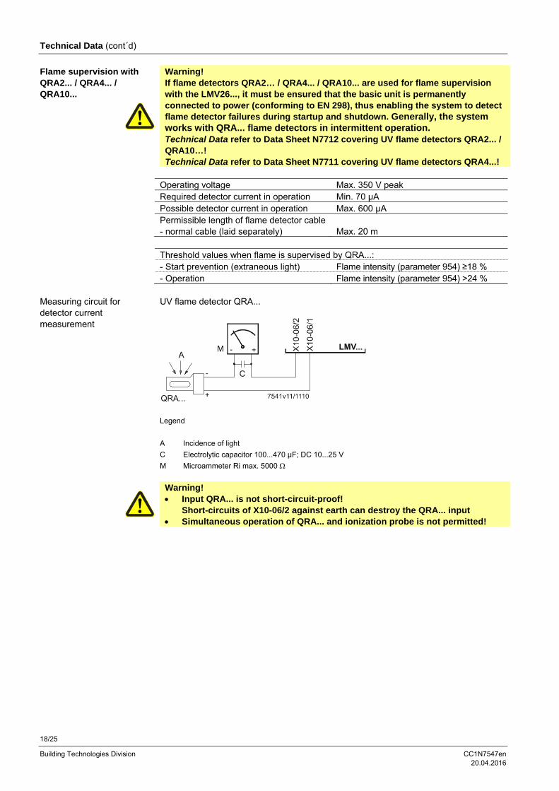
Warning! If flame detectors QRA2… / QRA4... / QRA10... are used for flame supervision with the LMV26..., it must be ensured that the basic unit is permanently connected to power (conforming to EN 298), thus enabling the system to detect flame detector failures during startup and shutdown. Generally, the system works with QRA... flame detectors in intermittent operation. Technical Data refer to Data Sheet N7712 covering UV flame detectors QRA2... / QRA10…! Technical Data refer to Data Sheet N7711 covering UV flame detectors QRA4...!
Operating voltage Max. 350 V peak Required detector current in operation Min. 70 µA Possible detector current in operation Max. 600 µA Permissible length of flame detector cable - normal cable (laid separately)
C Electrolytic capacitor 100...470 µF; DC 10...25 V
M Microammeter Ri max. 5000
Warning! Input QRA... is not short-circuit-proof!
Short-circuits of X10-06/2 against earth can destroy the QRA... input Simultaneous operation of QRA... and ionization probe is not permitted!
Flame supervision with QRA2... / QRA4... / QRA10...
Measuring circuit for detector current measurement
19/25
Building Technologies Division CC1N7547en 20.04.2016
Technical Data (cont´d)
No-load voltage at QRB... terminal (X10–05 pin 3)
Approx. DC 5 V
Max. perm. length of QRB... detector cable (laid separately)
3 m (wire – wire 100 pF/m)
Note A detector resistance of RF <500 is identified as a short-circuit and leads to safety shutdown in operation as if the flame had been lost.
For this reason, before considering the use of a highly sensitive photoresistive detector (QRB1B... or QRB3S), it should be checked whether this type of flame detector is indeed required! Increased line capacitance between QRB... connection and mains live wire L has an adverse effect on the sensitivity and increases the risk of damaged flame detectors due to overvoltage. Always run detector cables separately! Threshold values when flame is supervised by QRB...: Start prevention (extraneous light) with RQRB
Approx. 400 k Flame intensity ≥10 %
Operation with RQRB Approx. 230 k Flame intensity >16 %
Short-circuit detection with RQRB <0,5 k
0,1 1 10 100 1000
Bild
26
8e
/10
10
A flame detector resistance of RF <500 Ω is identified as a short-circuit and leads to safety shutdown in operation, like in the case of loss of flame.
Flame supervision with QRB…
20/25
Building Technologies Division CC1N7547en 20.04.2016
Technical Data (cont'd)
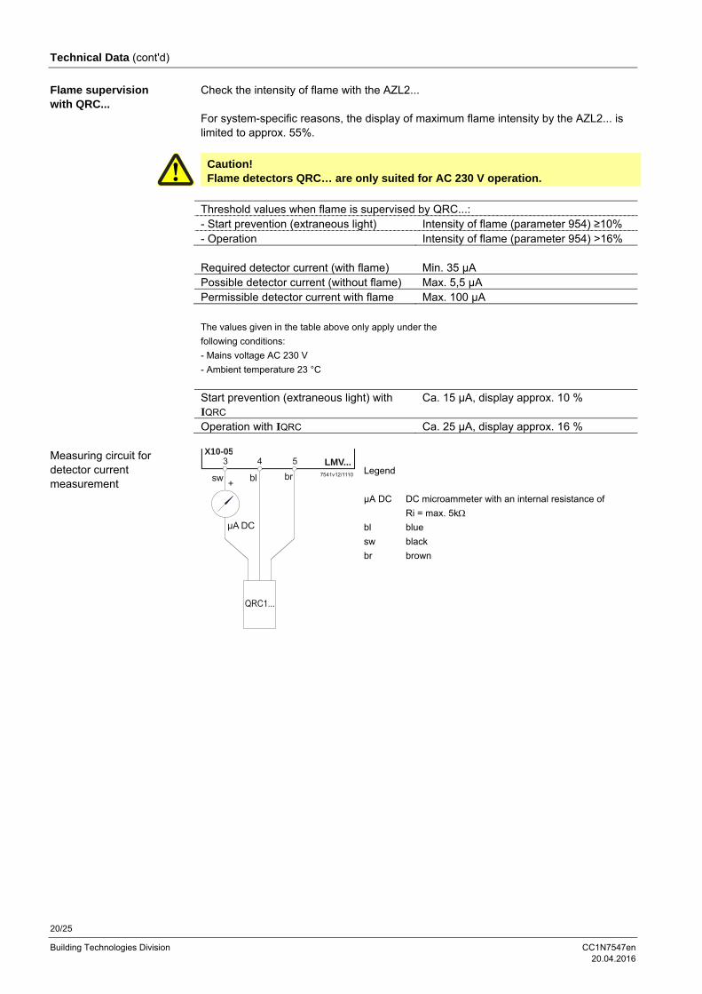
Check the intensity of flame with the AZL2... For system-specific reasons, the display of maximum flame intensity by the AZL2... is limited to approx. 55%.
Caution! Flame detectors QRC… are only suited for AC 230 V operation.
Threshold values when flame is supervised by QRC...: - Start prevention (extraneous light) Intensity of flame (parameter 954) ≥10% - Operation Intensity of flame (parameter 954) >16% Required detector current (with flame) Min. 35 µA Possible detector current (without flame) Max. 5,5 µA Permissible detector current with flame Max. 100 µA
The values given in the table above only apply under the
following conditions:
- Mains voltage AC 230 V
- Ambient temperature 23 °C
Start prevention (extraneous light) with IQRC
Ca. 15 µA, display approx. 10 %
Operation with IQRC Ca. 25 µA, display approx. 16 %
LMV...
sw bl br
µA DC
+7541v12/1110
3 54X10-05
Legend
µA DC DC microammeter with an internal resistance of
Ri = max. 5k
bl blue
sw black
br brown
Flame supervision with QRC...
Measuring circuit for detector current measurement
21/25
Building Technologies Division CC1N7547en 20.04.2016
Technical Data (cont´d)
Mains voltage AC 230 V -15% / +10% Mains frequency 50/60 Hz ±6% Power consumption <5 W (typically) (without actuator supply) Safety class I with parts according to II and III to
DIN EN 60730-1 Galvanic separation between mains voltage terminals and actuator signal lines and actuator supply lines
No
Degree of protection IP00 Note: The burner or boiler manufacturer (OEM) must ensure degree of protection IP40 to DIN EN 60529 for burner controls by adequate installation of the AGM60... The AGM60... together with the LMV26... is suited for installation under the burner hood or inside a control cabinet or control panel
Detection time fuel changeover <400 ms Switching frequency fuel changeover Min. 3 s Switching cycles fuel changeover Max. 5´000 Perm. mains primary fuse (externally) Max. 6.3 AT
Power must always be supplied via the basic unit (refer to chapter Inputs / Outputs)
Mains supply: Input current depending on the operating state of the unit
Mains voltage is monitored by the burner control Dimensions (W x H x D) 180.7 x 120.7 x 51.7 mm Mounting Top hat rail to DIN EN 60715,
35 mm or screwed Status input: Fuel selection, pressure switch Input currents and input voltages
- UeMax - UeMin - IeMax - IeMin
UN +10% UN -15% 1.5 mA peak 0.7 mA peak
Contact material recommendation for external switching contact, transducer (Pmax, POC)
Gold-plated silver contacts
Transition / settling behavior / bounce- Perm. bounce time of contacts when switching on/off
Max. 50 ms (after the bounce time, the contact must stay closed or open)
UN AC 230 V Voltage detection
- On - Off
AC 90...132 V <AC 40 V
Dual fuel switch unit AGM60...
Terminal output Inputs
22/25
Building Technologies Division CC1N7547en 20.04.2016
Technical Data (cont´d)
Total contact output: Rated voltage AC 230 V, 50/60 Hz Refer also Total contact output in chapter Terminal output Outputs
Individual contact loads: Fuel valve Rated voltage AC 230 V, 50/60 Hz Rated current 2 A Power factor Cos >0.4 Safety valve (SV) (magnetic clutch / oil pump) Rated voltage AC 230 V, 50/60 Hz Rated current 2 A Power factor Cos >0.4 Connections for pressure switch Rated voltage AC 230 V , 50/60 Hz Rated current 1.5 mA Power factor --- Power supply for pressure switch-max (Pmax) / POC (X5-02.3 or X22-02.3) IaMax <10 mA Fuel feedback to LMV26... (X31-02.1 or X31-02.2) IaMax <10 mA
Mains line LMV26... AGM60... Max. 3 m (100 pF/m) Fuel valves Max. 3 m (100 pF/m) Other lines Max. 3 m (100 pF/m) Fuel selector Max. 20 m (100 pF/m) Load controller (LR) Max. 20 m (100 pF/m)
Specification as per EN 60730-1 Type of shutdown or interruption of each circuit Shutdown with microswitch Single-pole Mode of operation Type 2 B
The cross-sectional areas of the power supply lines (L, N and PE) must be capable of carrying the rated currents according to the built-in unit fuse of the respective basic unit (max. 6.3 AT).
Min. cross-sectional area 0.75 mm²(single- or multi-core to VDE 0100)
Cable insulations must satisfy the relevant temperature requirements and environmental conditions. The fixed connected actuator cables must not be extended.
Terminal output Outputs
Cable lengths
Cross-sectional areas
Electrical connections of actuators
23/25
Building Technologies Division CC1N7547en 20.04.2016
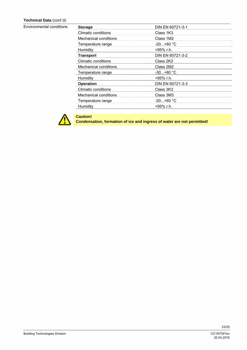
Technical Data (cont´d)
Storage DIN EN 60721-3-1
Climatic conditions Class 1K3
Mechanical conditions Class 1M2
Temperature range -20...+60 °C
Humidity <95% r.h.
Transport DIN EN 60721-3-2
Climatic conditions Class 2K2
Mechanical conditions Class 2M2
Temperature range -30...+60 °C
Humidity <95% r.h.
Operation DIN EN 60721-3-3
Climatic conditions Class 3K3
Mechanical conditions Class 3M3
Temperature range -20...+60 °C
Humidity <95% r.h.
Caution! Condensation, formation of ice and ingress of water are not permitted!
Environmental conditions
24/25
Building Technologies Division CC1N7547en 20.04.2016
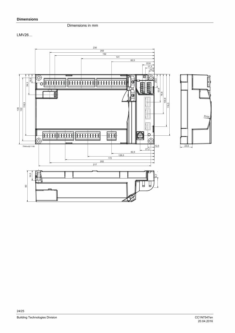
Dimensions
Dimensions in mm
230
202
192141
82,522,8
17,310,2
16,
5
39,
311
8,5
122
135
217
202
172128,5
82,527,2
12,5
19,7
60
25,
553
,6
76,6
100
,8
118
,5
23,5
R100
19,5
LMV26…
25/25
Building Technologies Division CC1N7547en 20.04.2016
Dimensions (cont´d)
Dimensions in mm
5,4
110
43,4
34
170
105
5,4
37,9
120
,7
180,7
51,
7
AGM60...
2016 Siemens AG Building Technologies Division, Berliner Ring 23, D-76437 Rastatt Subject to change!