Unleash The Power Of The Basic Atom Pro Unleash The Power Of The Basic Atom Pro Unleash The Power Of The Basic Atom Pro Unleash The Power Of The Basic Atom Pro Unleash The Power Of The Basic Atom Pro Revision 7.2.0.0 Revision 7.2.0.0 Revision 7.2.0.0 Revision 7.2.0.0 Revision 7.2.0.0 BasicATOMPro Syntax Manual BasicATOMPro Syntax Manual
Transcript
Unleash The Power Of The Basic Atom ProUnleash The Power Of The Basic Atom ProUnleash The Power Of The Basic Atom ProUnleash The Power Of The Basic Atom ProUnleash The Power Of The Basic Atom Pro
R e v i s i o n 7 . 2 . 0 . 0R e v i s i o n 7 . 2 . 0 . 0R e v i s i o n 7 . 2 . 0 . 0R e v i s i o n 7 . 2 . 0 . 0R e v i s i o n 7 . 2 . 0 . 0
Basic Micro warranties its products against defects in material andworkmanship for a period of 90 days. If a defect is discovered, BasicMicro will at our discretion repair, replace, or refund the purchase priceof the product in question. Contact us at [email protected] returns will be accepted without the proper authorization.
Basic Micro cannot be held responsible for any incidental, orconsequential damages resulting from use of products manufacturedor sold by Basic Micro or its distributors. No products from Basic Microshould be used in any medical devices and/or medical situations. Noproduct should be used in a life support situation.
Contacts
Web: http://www.basicmicro.com
Discussion List
A web based discussion board is maintained athttp://www.basicmicro.com
Updates
In our continuing effort to provide the best and most innovativeproducts, software updates are made available in the downloadsection of the Basic Micro website at http://www.basicmicro.com
5
Table of Contents
Ta
ble
of C
on
ten
tsT
ab
le o
f Co
nte
nts
Ta
ble
of C
on
ten
tsT
ab
le o
f Co
nte
nts
Ta
ble
of C
on
ten
ts
6
Contents
Introduction .................................................12What is the BasicATOM-Pro ? .......................................................... 12This Manual .................................................................................... 12On-line Discussion Forums .............................................................. 12Updates ......................................................................................... 12Technical Support ............................................................................ 12
The BasicATOM-Pro......................................15General Theory of Operation ............................................................ 16The ATOM-Pro Language ................................................................. 16How the ATOM-Pro Works ............................................................... 16Hardware ....................................................................................... 17
The Basic’s ...................................................19Line Labels ..................................................................................... 20RAM and Program Memory .............................................................. 20Variables ........................................................................................ 21Arrays ............................................................................................ 22Tables ............................................................................................ 23Aliases ........................................................................................... 24Variable Modifiers ........................................................................... 25Pin Variables ................................................................................... 28Constants ....................................................................................... 30Pin constants .................................................................................. 31
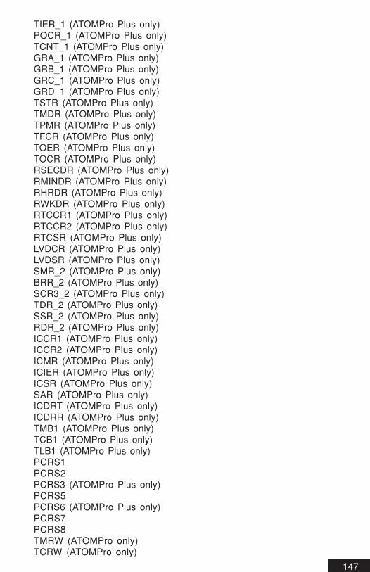
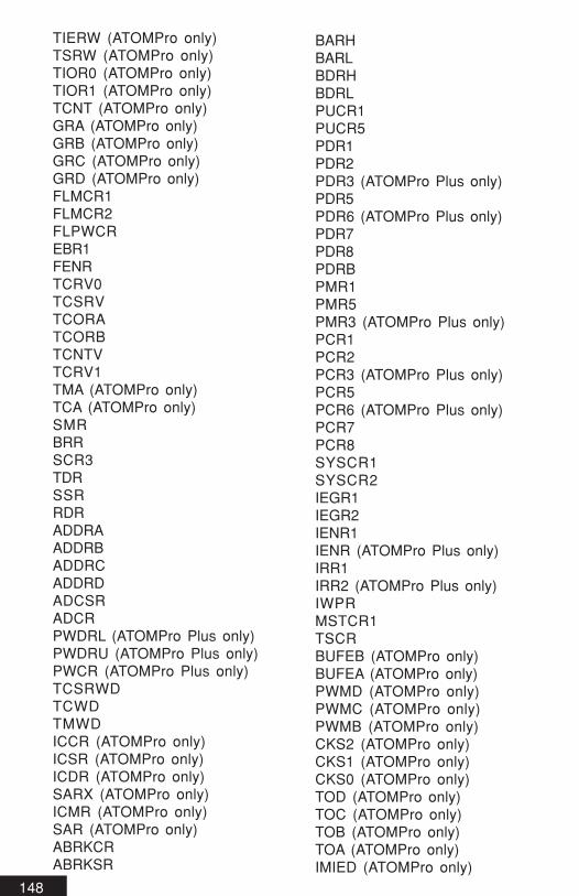
Reserved Words .........................................140Index ..........................................................158
9
10
11
Intr
od
uc
tio
nIn
tr
od
uc
tio
nIn
tr
od
uc
tio
nIn
tr
od
uc
tio
nIn
tr
od
uc
tio
n
Introduction
12
IntroductionWhat is the BasicATOM-Pro ?
The BasicATOM-Pro is the next generation of the BasicATOM productline. It is a self contained microcontroller which is programmed using anadvanced programming language modeled after BASIC, creating a costeffective and flexible way to program the BasicATOM-Pro hardware.The BasicATOM-Pro maintains the simplicity of Basic, but offers morepower.
This Manual
This manual in general applies to the BasicATOM-Pro programming syn-tax. Certain information may only pertain to a given version of the prod-uct.
This manual documents the BasicATOM-Pro’s programming language indepth . The main purpose of this manual is to teach the general syntax.
For more information about a particular device refer to its Data Sheet. AllData Sheets are available from the download section of the Basic Microwebsite. Http://www.basicmicro.com
We will continue to update and improve this manual. All updates willbe made available for download from our web site athttp://www.basicmicro.com.
On-line Discussion Forums
We maintain discussion forums at http://www.basicmicro.com in orderto help you to connect with a wide range of related information andusers. The discussion forums are free and will allow you to find infor-mation and help fast.
Updates
The BasicATOM-Pro software updates are available to new and currentcustomers from the Basic Micro website download section.
Technical Support
Technical support is provided via the Basic Micro online Support sys-tem and the discussion forums at www.basicmicro.com. When techni-cal support is required please fill out a Support Form in the Supportsection of our website. In order to assure a proper response pleaseinclude a copy of the program you are having problems with, the hard-
ware you are using, BasicATOM-Pro software version number,prototyping board and so on. By including this information with your e-mail, you can help us answer your questions much faster. Additionaltechnical support is often provided by our forum moderators in the discus-sion boards at our website(http://www.basicmicro.com).
13
14
15
The BasicATOM-Pro
Th
e B
asic
Ato
mT
he
Ba
sic
Ato
mT
he
Ba
sic
Ato
mT
he
Ba
sic
Ato
mT
he
Ba
sic
Ato
m
16
General Theory of Operation
The BasicATOM-Pro(here after refered to as the ATOM-Pro) is a tinycomputer, or better known as a microcontroller. The ATOM-Pro wasdesigned for use in a wide array of applications. The ATOM-Pro isbuilt around the Hitachi H8/TINY family, which contains internalmemory (2048 Bytes of RAM and 32K of FLASH program memory).Each ATOM has a built-in 5-volt regulator, a number of general-purpose I/O pins (TTL-level, 0-5 volts), commands for math and I/Opin operations and a serial port for in circuit programming.
The ATOM-Pro Language
The ATOM-Pro language is a simple, easy to learn platform based onBasicMicro’s MBasic as well as some specialized instructions for theATOM hardware.
How the ATOM-Pro Works
The ATOM-Pro’s software brains are not permanently stored in theCPU. This has many advantages. By not storing the software brainson the ATOM-Pro, new commands and functionality can easily beadded without the need for new hardware. Once a program is writtenthe ATOM-Pro’s software will compile what is needed to run correctly.
Since the software brain is not pre loaded, any program even thesmallest will have a minimum size of about 500 bytes out of32,000bytes regardless of the commands used. This method allowsminimum command / function duplication. If you were to use theSERIN or SEROUT commands more than once in your program onlyminimal code would be added. The ATOM-Pro can use the sameinternal code to perform the task of sending or receiving serial datathroughout the program. The same would apply to any other com-mands used in the program.
Small programs will increase in size rapidly until they reach about3KB in size. The rate at which a programs size grows will slow as itgrows simply because internal code will be used over again.
Hardware
There are several models of the ATOM-Pro available. For specificinformation refer to the data sheets regarding the version you areusing. All data sheets can be downloaded from the downloadssection of the Basic Micro website at http://www.basicmicro.com
The ATOM-pro is programmed at 115Kbps. This means that theATOM-Pro interface software will not work on a computer that doesnot have serial ports capable of 115Kbps. Most computers that havebeen shipped since 1996 have serial ports capable of 115Kbps.
If you are using a laptop or new computer that does not have thetraditional DB-9 serial connector the ATOM-Pro will program from aUSB to serial adapter.
The ATOM-Pro Integrated Development Environment(IDE) softwareonly works in a Windows environment. There is no DOS support andno plans for future DOS support.
17
18
19
The Basic’s
Th
e B
asic
’s
20
Line Labels
In order to access different sections of code you must use line labels.Unlike the original Basic language, MBasic does not use line numbers.
example:Loop: goto Loop ;This line repeats infinitely
The above goto statement jumps to a line label LOOP, which is infront of the GOTO statement. The above line will repeat infinitely. Linelabels can not be duplicated or used as variable names once defined asa label.
RAM and Program Memory
RAM, or random access memory, is where variable values, andsystem values are stored. RAM is also used to store the returnlocation of GOSUB statements. The ATOM-Pro has about 2000 bytesof user RAM available.
Program Memory is the memory where your program will reside. Thesize of available program memory will limit the size of your program.The more complicated the program , the more memory you will use.Most ATOM-Pro modules have 32kbytes of program memory(Somehave 56kbytes of memory).
Variables
Variables are used to store temporary information in the program. Theyare created using the VAR keyword. Variables can be BITs, NIBBLEs,BYTEs, WORDs and LONGs. Before you can use a variable it must bedefined.
example:Variable name: Variable: Size:Temp Var Byte
The above states Temp is allocated a byte (8 bits) of ram
Variable names must start with a letter. They can contain letters,numbers and special characters. However they can not be the samename as ATOM-Pro reserved words or labels used in a program. Thesame variable name can not be defined twice. The ATOM-Pro doesnot distinguish between upper and lower case, so the name “TEMP”is equivalent to “temp”. The maximum character length can be up to1024 characters.
Throughout this manual and when dealing bits, bytes, words ,longsand floats will be referred to often. The following is a quick breakdown of the values these different variable types can hold:
Type Bit Size RangeBit 1 1 or 0Nib 4 0 to 15Byte 8 0 to 255SByte 8 -127 to +128Word 16 0 to 65535SWord 16 -32767 to +32768Long 32 0 to 4,294,967,295SLong 32 -2147483647 to +2147483648Float 32 +-2^-126 to 2^127
Some examples of defined variables:
DOG Var Bit ;0 or 1POST Var Nib ;0 to 15LOG Var Byte ;0 to 255STICK Var Word ;0 to 65535TREE Var Long ;0 to 4,294,967,295
21
22
Arrays
As your programs begin to perform more complex tasks, there will betimes when you want a variable to hold many values. An Array is astructure that can store multiple values of the same type.
example:Temp var Word(5)
The number 5 in parenthesis shows the variable temp has 5 cells.Once the array has been defined, each cell can be accessed by itsnumber:
The above will assign the value of 10 to the first cell in the 5 cellarray, 25 to the second cell and so on. Using arrays can simplify yourprogram as shown below:
Temp Var Byte(5) ;variable temp now has 5 cellsCntr Var Byte
For Cntr = 0 to 4 ;Set each cell to Cntr + 2Temp(Cntr) = Cntr + 2
Next
The above code example will load each array, 0 to 4 (5 cells) with thearray number + 2. To do this manually:
note:The ending NULL(0) is usefull when using tables with STR
modifiers.
23
24
Aliases
Aliases are alternate names for defined variables. As an example:
DOG Var Byte ;DOG is assigned as an 8 bit variable (Byte)CAT Var DOG ;CAT now points to the variable DOG
In the above example if DOG were equal to 10, any time the variableCAT was accessed it would equal 10 since it points to the sameRAM location. Aliases are a good idea when you want to use atemporary variable with a name that suits its function.
Variable Modifiers
Variable modifiers are used to access only parts of a variable.
In example 1 we show how to alias a variable(point a new variable atthe data of a previously defined variable) using a variable modifier. Inexample 1 the “highbyte” modifier is used. This points the aliasedvariable, “Cat”, at the high byte(bits 8-15) of “Dog”.
example 1:Dog Var WordCat Var Dog.HighByte
In example 2 we show how to access parts of variables on the fly. Inthis example “Cat” is being loaded with a value from “Dog”. Here weare geting the second byte of the two byte(word) variable, “Dog”, andstoring it in “Cat” by using the “Byte1” modifier.
example 2:Dog Var WordCat Var Byte
Cat = Dog.Byte1
25
26
The table below shows all the different variable modifiers that canbe used:
Modifier Create alias to
LOWBIT bit 0 of variable
BIT0 bit 0 of variable
BIT1 bit 1 of variable
BIT2 bit 2 of variable
BIT3 bit 3 of variable
BIT4 bit 4 of variable
BIT5 bit 5 of variable
BIT6 bit 6 of variable
BIT7 bit 7 of variable
BIT8 bit 8 of variable
BIT9 bit 9 of variable
BIT10 bit 10 of variable
BIT11 bit 11 of variable
BIT12 bit 12 of variable
BIT13 bit 13 of variable
BIT14 bit 14 of variable
BIT15 bit 15 of variable
BIT16 bit 16 of variable
BIT17 bit 17 of variable
BIT18 bit 18 of variable
BIT19 bit 19 of variable
BIT20 bit 20 of variable
BIT21 bit 21 of variable
BIT22 bit 22 of variable
BIT23 bit 23 of variable
BIT24 bit 24 of variable
BIT25 bit 25 of variable
BIT26 bit 26 of variable
BIT27 bit 27 of variable
BIT28 bit 28 of variable
BIT29 bit 29 of variable
BIT30 bit 30 of variable
BIT31 bit 31 of variable
HIGHBIT highest bit of variable
Modifier Create alias to
LOWNIB nibble 0 of variable
NIB0 nibble 0 of variable
NIB1 nibble 1 of variable
NIB2 nibble 2 of variable
NIB3 nibble 3 of variable
NIB4 nibble 4 of variable
NIB5 nibble 5 of variable
NIB6 nibble 6 of variable
NIB7 nibble 7 of variable
HIGHNIB highest nibble of variable
LOWBYTE byte 0 of variable
BYTE0 byte 0 of variable
BYTE1 byte 1 of variable
BYTE2 byte 2 of variable
BYTE3 byte 3 of variable
HIGHBYTE highest byte of variable
LOWWORD word 0 of variable
WORD0 word 0 of variable
WORD1 word 1 of variable
HIGHWORD word 1 of variable
Note: Variable modifiers can also be used in code statements
example:
if myvar.bit0 = 1 then dosomething
27
28
Pin Variables
Pin variables are just like any other variables except that the states ofthe individule bits in the variables are the states/directions of thecorresponding pin.
DIRE a 32bit variable accessing the directions of P0-P31.DIRS a 16bit variable accessing the directions of P0-P15.DIRES a 16bit variable accessing the directions of P16-P31.DIRL an 8bit variable accessing the directions of P0-P7.DIRH an 8bit variable accessing the directions of P8-P15.DIREL an 8bit variable accessing the directions of P16-P23.DIREH an 8bit variable accessing the directions of P24-P31.DIRA a 4bit variable accessing the directions of P0-P3.DIRB a 4bit variable accessing the directions of P4-P7.DIRC a 4bit variable accessing the directions of P8-P11.DIRD a 4bit variable accessing the directions of P12-P15.DIREA a 4bit variable accessing the directions of P16-P19.DIREB a 4bit variable accessing the directions of P20-P23.DIREC a 4bit variable accessing the directions of P24-P27.DIRED a 4bit variable accessing the directions of P28-P31.DIR# (# is any number from 0 to 31) is a variable that accessesthe direction of P0 - P31 individually.
INE a 32bit variable accessing the states of P0-P31.INS a 16bit variable accessing the states of P0-P15.INES a 16bit variable accessing the states of P16-P31.INL an 8bit variable accessing the states of P0-P7.INH an 8bit variable accessing the states of P8-P15.INEL an 8bit variable accessing the states of P16-P23.INEH an 8bit variable accessing the states of P24-P31.INA a 4bit variable accessing the states of P0-P3.INB a 4bit variable accessing the states of P4-P7.INC a 4bit variable accessing the states of P8-P11.IND a 4bit variable accessing the states of P12-P15.INEA a 4bit variable accessing the states of P16-P19.INEB a 4bit variable accessing the states of P20-P23.INEC a 4bit variable accessing the states of P24-P27.INED a 4bit variable accessing the states of P28-P31.IN# (# is any number from 0 to 31) is a variable that accesses thestate of P0 - P31 individually.
OUTE a 32bit variable accessing the states of P0-P31.OUTS a 16bit variable accessing the states of P0-P15.OUTES a 16bit variable accessing the states of P16-P31.OUTL an 8bit variable accessing the states of P0-P7.
OUTH an 8bit variable accessing the states of P8-P15.OUTEL an 8bit variable accessing the states of P16-P23.OUTEH an 8bit variable accessing the states of P24-P31.OUTA a 4bit variable accessing the states of P0-P3.OUTB a 4bit variable accessing the states of P4-P7.OUTC a 4bit variable accessing the states of P8-P11.OUTD a 4bit variable accessing the states of P12-P15.OUTEA a 4bit variable accessing the states of P16-P19.OUTEB a 4bit variable accessing the states of P20-P23.OUTEC a 4bit variable accessing the states of P24-P27.OUTED a 4bit variable accessing the states of P28-P31.OUT# (# is any number from 0 to 31) is a variable that accessesthe state of P0 - P31 individually.
IN and OUT pin variables are interchangable. Either one can be usedto read or write a pin state. The two different names are provided tomake code more easy understood.
29
30
Constants
Constants are similar to variables except their values are set at com-pile time and can not be changed. When creating a program it can bebeneficial to use constants for certain values that don’t change.
example:Meter CON 1 ;Meter = 1Centimeter CON Meter * 100 ;Centimeter = 100Millimeter CON Centimeter * 10 ;Millimeter = 1000
In the above example “centimeter” and “millimeter” values were de-rived from the constant “meter”. There are a 100 centimeters in a meterand a 1000 millimeters in a meter.
Pin names are also constants so they can be used in the followingway:
RedLed Con P0GreenLed Con P1
MainHigh RedLedHigh GreenLed
Goto Main
RedLed and GreenLed are now constants that point to pin 0 and pin 1.When writing complex programs it may be beneficial to use constantsas shown above.
Pin constants
Pin constants are simple predefined constants for the different pinnumbers on the ATOM-Pro. All ATOM-Pro modules/boards have 16common I/O pin names. See specific ATOM-Pro module datasheetsfor each modules extended list of pin names.
Also each ATOM-Pro module has two specialized pins(S_IN andS_OUT) for programming and for use as serial input/output.
31
32
33
Preprocessor
Pr
ep
ro
ce
sso
rP
re
pr
oc
esso
rP
re
pr
oc
esso
rP
re
pr
oc
esso
rP
re
pr
oc
esso
r
34
Preprocessor
The ATOM-Pro compiler’s preprocessor commands are used to includeexternal files and to conditional compie sections of code.
Including files
By using the #include preprocessor directive the user can modularizetheir program. The #include directive acts like a compile time paste.The text in the file specified in the #include directive will be placedinto the users program at the location of the directive at compile time.
For example, if you have a basic file called “myfuncs.bas” you canadd the code from this file to your compiled program by using the#include directive like this:
maingosub myfunc1 ;myfunc1 is defined in myfuncs.basgoto main
#include “myfuncs.bas”
This assumes that the myfuncs.bas file is in the same directory as themain program. If the included file is not in the same directory youmust include the full or partial path name.
For example, if “myfuncs.bas” is in a sub directory of the directory themain program is in you can:
#include “mysubdir\myfuncs.bas”
Or you can specify the full path:
#include “c:\mybasprogs\mysubdir\myfuncs.bas”
Conditional compiling
Conditional compiling is used when you don’t always want somesections of your code to be compiled into the program. Using theconditional directives you can specify whether certain lines of codeare compiled into your program or not based on whether somethingwas previously defined.
35
#IF constant expression
The #IF directive is used to specify user code that will only becompiled in the program if the constant expression is true(ie nonzero).
Example:#IF mycon = 120
...code...#ENDIF
#IFDEF name
The #IFDEF directive is a special case of the #IF directive. Itsargument must be a name(ie label,variable or constant name). If thename was defined previously in the program the code inside thedirective will be compiled.
Example:mycon con 10#IFDEF mycon
...code...#ENDIF
#IFNDEF name
The #IFNDEF directive is a special case of the #IF directive. Itsargument must be a name(ie label,variable or constant name). If thename was not defined previously in the program the code inside thedirective will be compiled.
Example:#IFNDEF mycon
...code...#ENDIF
#ELSEIF constant expression
The #ELSEIF directive is used to allow multiple conditions easily
Example:#IF mycon = 120
...code...#ELSEIF mycon = 130
..code..#ELSEIF mycon = 140
..code..#ENDIF
36
#ELSEIFDEF name
The #ELSEIFDEF directive is used to allow multiple conditions easily
Example:#IFDEF mycon1
...code...#ELSEIFDEF mycon2
..code..#ELSEIFDEF mycon3
..code..#ENDIF
#ELSEIFNDEF name
The #ELSEIFNDEF directive is used to allow multiple conditionseasily
Example:#IFNDEF mycon1
...code...#ELSEIFNDEF mycon2
..code..#ELSEIFNDEF mycon3
..code..#ENDIF
#ELSE
The #ELSE directive can be used with any #IF directive. When the#IF directive is false the code inside the #ELSE directive will beadded to the compiled program instead.
Example:#IF mycon = 10
...code...#ELSE
..code..#ENDIF
#ENDIF
All conditional compiling directives must end with an #ENDIF.
37
38
39
Math
Ma
th
Ma
th
Ma
th
Ma
th
Ma
th
40
Numerical Types
Numbers can be written in different ways. Binary numbers are writtenusing only 0 and 1. Hexadecimal uses characters ‘0’ to ‘F’. Binary andhexadecimal numbers must have an indicator.
1234 or d’1234’ : Standard Decimal number$1F2A or 0x1F2A : Hexadecimal notation%1001 : Binary notation
The character $(string) or “0x” indicates Hexadecimal and the percent-age sign % indicates binary data. These special characters must beused in order to let the Atom know what numerical types they are.
Operator Precedence
The ATOM-Pro uses standard algebraic syntax. In the ATOM-Pro 2+2*5/10 = 3. This is because in the ATOM-Pro each math operator has aprecedence. The multiply and divide operators have equal precedence.In the above calculation 2*5 will be calculated first (equaling 10), thenthe divide by 10 (equals 1), then the addition of 2 (equaling 3). You canuse parenthesis to force specific orders (i.e.: ((2+2)*2) /2 would calcu-late the value the way the Basic Stamp does(ie left to right with noprecedence).
The following is a list of math functions the ATOM-Pro can perform.
UNARY Commands-(NEG) expression Negate valueABS expression Absolute valueSIN expression sine of value(0-255)COS expression cosine of value(0-255)DCD expression 2 to the nth power(n = value)NCD expression smallest power of 2 that is GREATER
than value.SQR expression square root of value.BIN2BCD expression Integer to Packed BCD formatBCD2BIN expression Packed BCD to integer.RANDOM expression Generate Rangom value with seed
expressionNOT expression Logical inverse
Floating Point UNARY CommandsTOINT expression Converts a Floating Point value to an
Integer value.TOFLOAT expression Converts an Integer value to a Float
ing Point value.FSQRT expression Square RootFSIN expression Sin(range: PI/2 to -PI/2)FCOS expression Cos(range: PI/2 to -PI/2)FTAN expression Tan(range: PI/2 to -PI/2)FASIN expression ArcSin(range: 1 to -1)FACOS expression ArcCos(range: all values)FATAN expression ArcTan(range: 1 to -1)FSINH expression Hyperbolic Sin(range: 1.13 to -1.13)FCOSH expression Hyperbolic Cos(range: 1.13 to -1.13)FTANH expression Hyperbolic Tan(range: 1.13 to -1.13)FATANH expression Hyperbolic ArcTan
(range: 1.13 to -1.13)FLN expression Natural Log(range: 9.58 to 0.1)FEXP expression Exponent(range: 1.13 to -1.13)
41
42
= Equal
<> Not Equal
Compare Op. Description
BINARY Commandsexp1 + exp2 Add exp1 to exp2exp1 - exp2 Sub exp2 from exp1exp1 * exp2 Mulitply exp1 by exp2exp1 ** exp2 Get high 32bits of a multiplyexp1 */ exp2 Fractional Multiplyexp1 / exp2 Divide exp1 by exp2exp1 // exp2 Mod exp1 by exp2exp1 MAX exp2 smaller of the two expressions.exp1 MIN exp2 larger of the two expressions.exp1 DIG exp2 digit of exp1 at exp2 position.exp1 REV exp2 reverses exp2 bits of exp1 starting
with LSB
Bitwise Operators
Bitwise operators are commands that directly effect the bits of avalue.
Bitwise operatorsexp1 & exp2 And exp1 with exp2exp1 | exp2 Or exp1 with exp2exp1 ^ exp2 XOr exp1 with exp2exp1 >> exp2 Shift exp1 right by exp2exp1 << exp2 Shift exp1 left by exp2~(NOT) expression Invert exp1!(NOT) Invert exp1
Comparison Operators
Comparison operators are used when comparing two or more values.Examples are the IF...THEN and LOOKDOWN commands.
< LessThan
> GreaterThan
<= LessThan Equal
>= GreaterThan or Equal
Logical Operators
Logical operators are slightly different in use than comparison opera-tors. When an IF...THEN statement contains more than one compari-son you must combine them using a logical operator. The examplebelow illustrates this:
If (Variable < 100) AND (Variable > 10) Then Label
As you can see from the example if BOTH are true then the programjumps to the label.
Logical Op. Description
AND Logical AND
OR Logical OR
XOR Logical Exclusive OR
NOT Logical NOT
43
44
Floating Point Format
The floating point math the ATOM-Pro uses differs some what fromthe normal IEEE 754 floating point standard.
32.31.30.29.28.27.26.25.24.23.22.21.20...0IEEE S E E E E E E E E M M M M...MATOM E E E E E E E E S M M M M...M
Note: All variables that will contain a floating point number must be aFLOAT type variable.
45
Command Modifiers
Co
mm
an
d M
od
ifier
sC
om
ma
nd
Mo
difie
rs
Co
mm
an
d M
od
ifier
sC
om
ma
nd
Mo
difie
rs
Co
mm
an
d M
od
ifier
s
46
Modifier usage
Command modifiers can be used to modify/enhance data in a com-mand directly. Modifiers can be used with any commands that show{Modifier or Mods} in their syntax.
Signed I/O Modifierssdec Decimal Valueshex Hexadecimal Valuesbin Binary Value
Indicated I/O Modifiersihex Hexadecimal Valueibin Binary Value
Combination I/O Modifiersishex Hexadecimal Valueisbin Binary Value
Output Only Modifiersrep Output character n timesreal Output Floating point numbers
Input Only Modifierswaitstr Waits until values received match arraywait Waits util values received match string of valuesskip Skip n values
HEX - DEC - BINdesc(input):
Convert input ASCII characters to binary. Input must be inHEX,DEC or BIN format
desc(output):Convert a binary value to ASCII characters in HEX,DEC or BIN
format
syntax:modifier{#1} arg{\#2}#1: optional number that sets a maximum number of digits to pass#2: optional value that sets a minimum number of digits to pass
example:command args,[dec2 1234\2] ;output “34”
SDEC - SHEX - SBINdesc(input):
Convert input ASCII characters to binary. Input must be inHEX,DEC or BIN format. “-” is a valid sign character.
desc(output):Convert a binary value to ASCII characters in HEX,DEC or BIN
format with sign(“-”) if negative
syntax:modifier{#1} arg{\#2}#1: optional number that sets a maximum number of digits to pass#2: optional value that sets a minimum number of digits to pass
example:command args,[sdec -1234] ;output “-1234”
47
48
IHEX - IBINdesc(input):
Convert input ASCII characters to binary. Input must be inHEX,DEC or BIN format. Input characters are ignored until a validindicator character is received
desc(output):Convert a binary value to ASCII characters in HEX,DEC or BIN
format. An indicator character is passed first.
indicator chars:HEX: “$”BIN: “%”
syntax:modifier{#1} arg{\#2}#1: optional number that sets a maximum number of digits to pass#2: optional value that sets a minimum number of digits to pass
example:command args,[ihex $ABCD] ;output “$ABCD”
ISHEX - ISBINdesc(input):
Convert input ASCII characters to binary. Input must be inHEX,DEC or BIN format with optional sign character(“-”). Input charac-ters are ignored until a valid indicator character is received
desc(output):Convert a binary value to ASCII characters in HEX,DEC or BIN
format. An indicator character is passed first. If the value is negativea sign character is pased next(“-”).
indicator chars:HEX: “$”BIN: “%”
syntax:modifier{#1} arg{\#2}#1: optional number that sets a maximum number of digits to pass#2: optional value that sets a minimum number of digits to pass
Reads the pin, debounces the button input, performs an auto-repeat ifactivated, and branches to a label if logical state is active. The Buttonmay be activated in either a low state or a high state based on thelogicalstate.
Pin is an expression of the pin number the button/switch isconnected to. The pin will be made an input.
PressedState is an expression(0 or 1) which specifies thevoltage when the button is pressed(Gnd or Vdd).
RepeatDelay is an expression(0–255) which sets the functions ofthe button command. If equal to 0 debounce and auto-repeat aredisabled. If equal to 255, BUTTON executes a debounce(oneloop), but auto-repeat is disabled. All other values(1-254)are the number of program loops the button command mustexecute before autorepeat begins.
RepeatRate is an expression(0–255) of the number of programloops BUTTON executes before each repeat
WorkByte is a work space variable used internally by theBUTTON command to store current loop counts for use whendebouncing, delaying, and auto-repeating. This variable must beunique inside the program loop BUTTON is running in.
Logicalstate is an expression(0 or 1) which determines thelogical state the button must be in for a branch to occure(pressedor not pressed).
Label is the label of the location in the user program to jump/branch to when the targetstate is triggered.
Explanation
The BUTTON command works much like a key on a PC keyboard.When a switch/button is closed or opened(depending on commandarguments), the BUTTON command will jump/branch to the specifiedlabel. The BUTTON command also allows the user to specify thedelay before auto-repeating and how fast to auto-repeat(if at all).
DEBOUNCEWhen a switch or button contact is closed the mechanical connec-tions may bounce. This can cause a period where the state of theswitch or button can not acurately be determined. Debouncing theinput rereads the input state one program loop after the first read ofthe pin the switch/button is connected to inorder to confirm the stateof the input.
57
58
Clear
CLEARClear user RAM.
Explanation
The Clear command will clear (Set to 0’s) all of the user ram. User ramis set aside space for all the variables a user program will use.
59
Count
COUNT pin, period, variable
Count the number of cycles (0-1-0 or 1-0-1) on the specified pin duringperiod number of milliseconds and store that number in variable.
Pin is an expression of the I/O pin number to use.This pin will be placed into input mode.
Period is an expression(1 to 4294967296) of the time in milliseconds during which to count.
Variable is a variable where the count will be stored.
Explanation
COUNT checks the state of PIN in a tight loop and will count the low tohigh transitions. COUNT is ideal for figuring out frequency of certainwaves or timings based on an incoming signal.
60
Debug
DEBUG [{Options} item, {{Options} item}]Sends values of specified variables or constants to the debug watchwindow.
Options are DEC, HEX, BIN or REAL. These modifiers willconvert Item to DEC = Decimal, HEX = Hexadecimal, BIN =Binary digits or REAL = Value.
Item can be a constant or variable. There is no limit to the amountof items used other than program memory.
Explanation
The DEBUG command will send any values stored in a given variableor constant to the debug watch window. The DEBUG command isalso linked with the IDE’s In Circuit Debugger (Refer to the In CircuitDebugger section of the BasicMicro IDE users guide). Variables usedby themselves are automatically truncated to character size.
61
Debugin
DEBUGIN [(Options) item]Receives byte values from the IDE DEBUG window and stores themin a specified variable on the Atom.
Options are DEC, HEX, BIN or REAL. These modifiers willconvert Item to DEC = Decimal, HEX = Hexadecimal, BIN =Binary digits or REAL = Value.
Item can only be a byte variable. It stores the received byte valuein the specified variable.
Explanation
The DEBUGIN command allows you to send data to your program on-the-fly from the IDE DEBUG Watch Window and stores the data in thespecified variable. This can be useful for adjusting a program on thefly.
62
Disable
DISABLE {intname}Disable the specified interrupt. If no interrupt is specified disable allinterrupts.
IntName is the name of the interrupt to disable. See theONINTERRUPT directive for a list of interrupt names.
Explanation
DISABLE turns off the spcified interrupt by clearing its interrupt enablebit. Any other register settings remain the same. If no interrupt isspecified the global interrupt enable bit is cleared.
63
Do...While
Do....user code....While expression
Repeat a group of commands while expression is true
Expression is any combination of variables, constants,mathmatical and/or logic operators
Explanation
Execute a group of commands while some expression is true.DO...WHILE will run at least once. A True value is any value other thanzero(0).
64
DTMFout
DTMFOUT pin,{playtime,pausetime,}[,key...]Generate dual-tone, multifrequency tones for DTMF devices. Thetones a touch tone telephone make are examples of DTMF tones.
Pin is an experssion of the I/O pin number to use. Thispin will be set to an output during tone generation. After tonegeneration is complete, the pin is left as an input.
Playtime is an optional expression(0 to 65535) of the time to playthe tone in milliseconds. If playtime is not used DTMFout defaultsto 200 ms on.
Pausetime is an optionalexpression(0 to 65535) of the length ofsilence after each tone. If pausetime is not used DTMFout defaults to 50 ms. If playtime is used then pausetime is required.
Key is a variable or constant specifying the DTMF key to send.
Key # Telephone Key0 to 9 Digits 0 - 910 Digit *11 Digit #12—15 Fourth column tones A through D
Explanation
DTMF tones are a simple form of analog/digital conversion used tocommunicate digital commands via an analog signal. These signalsare ussually used to dial a telephone. For all intents the DTMFOUTcommand acts as a telephone keypad. DTMF tones are generatedusing pulse width modulation to digitally create the equivilent of twosine wave waveforms at different frequencies. Due to the PWMgeneration of the tones high-frequency noise will be present on theoutput. This noise must be filtered with a lowpass filter circuit.
65
DTMFout2
DTMFOUT2 pin1 \ pin2,{playtime,pausetime,}[,key...]Uses two pins to generate dual-tone, producing a cleaner signal (i.e.,telephone "touch" tones).
Pin1 / Pin2 are expressions for the I/O pins to use. These pinswill be set as outputs during tone generation. After tone generation is complete, the pins are set to inputs.
Playtime is an optional expression(0 to 65535) of the time to playthe tone in milliseconds. If playtime is not used DTMFout defaultsto 200 ms on.
Pausetime is an optionalexpression(0 to 65535) of the length ofsilence after each tone. If pausetime is not used DTMFout defaults to 50 ms. If playtime is used then pausetime is required.
Key is a variable or constant specifying the DTMF key to send.
Tone # Telephone Key0 to 9 Digits 0 - 910 Digit *11 Digit #12—15 Fourth column tones A through D
Explanation
The DTMFOUT2 command follows the same basic format asDTMFOUT (refer to DTMFOUT), except it generates the multifre-quency tones on two pins. These two pins can be tied together usinga 390 ohms resistor. The tones generated by DTMFOUT2 are madeof square wave frequencies. This produces clearer and louder tonesbut some DTMF decoders may have trouble with it
66
Enable
EnABLE {intname}Enable the specified interrupt. If no interrupt is specified enable allinterrupts.
IntName is the name of the interrupt to disable. See theONINTERRUPT directive for a list of interrupt names.
Explanation
ENABLE turns on the spcified interrupt by setting its interrupt enablebit. Any other register settings remain the same. If no interrupt isspecified the global interrupt enable bit is set
67
Enablehserial
ENABLEHSERIALEnable the hardware serial system(SCI3)
Explanation
ENABLEHSERIAL is a compile time directive that tells the compiler toadd support for the hardware serial system(SCI3)
68
Enablehserial2 (ATOM-Pro Plus only)
ENABLEHSERIAL2Enable the hardware serial system(SCI3_2)
Explanation
ENABLEHSERIAL2 is a compile time directive that tells the compilerto add support for the hardware serial system(SCI3_2). This directiveis only supported by the ATOM-Pro Plus processors.
69
Enablehservo
ENABLEHSERVO pinmask,minpulse,maxpulse,resfreshEnable the hardware servo control system
Pinmask is a constant that specifies a mask for which I/O pinswill be taken over by the HSERVO system.
Minpulse is a constant of the minimum pulse width in useconds ofthe servo control pulses
Maxpulse is a constant of the maximum pulse width in usecondsof the servo control pulses
Refresh is a constant of the refresh rate in milliseconds.
Explanation
ENABLEHSERVO is a compile time directive that tells the compilerto add support for the hardware servo control system. The HSERVOsystem uses the TimerW(or TimerZ0 in ATOM-Pro Plus) to produceinterrupt driven signals for up to 32 servos. The pinmask is a 32bitbinary number where each bit specifies whether that particular pin ishandled by the hardware servo system or by user code. A bit set aslogical 1 enables that pin for the hardware servo system.
Example:ENABLEHSERVO %11110000,200,2200,20
In the example pins P4-P7 are handled by the hardware servo sys-tem. The minimum pulse width is 200us and the maximum pulsewidth is 2200us giving a total swing of 2000us on the servo. Therefresh rate of the servos is every 20ms.
70
End
ENDEnds the program.
Explanation
END will stop the program until reset. All I/O lines will remain at theirlast know state.
71
Exception
EXCEPTION label
Clears the return stack and jumps to label.
Label is any root lable. A root label is any label not defined in agosub routine.
Explanation
Exception’s puprose is to jump out of nested subroutines(ieGOSUBs). Using a goto to jump out of a GOSUB will leave a returnvalue on the stack and eventually may cause the stack to overflow.EXCEPTION works just like a GOTO except it clears any returnvalues from the stack.
72
For...Next
FOR variable = startVal to endVal {STEP stepVal} ... NEXT
Create a repeating loop that executes the program lines betweenFOR and NEXT, increment or decrement the variable according tostepVal, until the value of the variable passes the endVal.
Variable is where to store the current count.
StartVal is an expression of the initial value of the variable.
EndVal is an expression of the end value of the variable. Whenthe value of the variable passes endVal execution stops and theprogram goes to the instruction after Next.
StepVal is an optional expressionof the amount variableincreases or decreases with each trip through the FOR/NEXT loop. Negative values for StepVal will decrement andPositive values will increment.
For counter = 20 to 1 step -1 ; this will decrement -1
For counter = 1 to 20 step 1 ; this will increment +1
Explanation
The FOR...NEXT loop will allow your program to execute a series ofinstructions for a specific number of repetitions. By default, thecounter variable is incremented by 1 each time through the loop. Itwill continue to loop until the result of the counter is outside of therange set by StartValue and EndValue.
Note: The variable type must match the Start,End and Step valuetypes. If Floating Point numbers are used for Start,End and Step,variable MUST be a FLOAT type variable.
73
Freqout
FREQOUT pin, duration, freq1{,freq2}Generates one or two tones for a specified duration.
Pin is an expression of the I/O pin number to use. Thispin will be put into output mode during generation of tones andleft in that state after the instruction is completed.
Duration is an expression of the length in milliseconds of thetone(s).
Freq1 is an expression of the frequency(Hz, 0 to 32767) in hertzof the first tone.
Freq2 is an expression of the frequency(0 to 32767 Hz) in hertzof the optional second tone
Explanation
FREQOUT generates one or two sine waves using a pulse-widthmodulation algorithm. The FREQOUT command can be used to playtones through a speaker or audio amplifier. FREQOUT can also beused to play simple songs. A filtering circuit is required with mostspeakers.
74
GetHSERVO
GETHSERVO pin,position{,idle}Get the current position of the specified servo. Optionally getwhether the servo is idle or not.
Pin is an expression of the I/O pin number to check servoposition on.
Position is a variable where GETHSERVO will store the currentposition of the specified servo
Idle is an optional variable where GETHSERVO will store thecurrent state of the servo. A value of $FFFFFFFF(ie Non-Zero)means the servo is idle(at it’s final position)
Explanation
Gethservo is used to determine what position a servo is at andwhether it has finished moving to it’s final position.
75
Gosub...Return
GOSUB LabelStore the address after GOSUB, then go to the point in the programspecified by Label.
Label specifies the section of the program to jump to.
Explanation
GOSUB is a close relative of the GOTO command. The GOSUBcommand tells the program to go execute code at the beginning ofthe specified label. Unlike GOTO, GOSUB stores the location of thenext line of code immediately following itself, when the programencounters a RETURN instruction in the subroutine, it then tells theprogram to return to the stored location.
When GOSUBs are used, a RETURN statement is necessary (at theend of the subroutine) to take the program back to the instructionafter the most recent GOSUB.
Important Notes
Each GOSUB call uses 4 bytes of ram from the STACK to store thereturn address.
76
Goto
GOTO LabelGo to the point in the program specified by Label.
Label specifies the section of the program to jump to.
Explanation
The GOTO command makes a program jump to a specific label andexecute the code that starts at that location. BASIC programs areread from left to right / top to bottom, just like in the English lan-guage. The GOTO command forces the program to jump to anothersection of code.
77
High
HIGH pinMakes the specified pin an output and sets it to high( +5 volts is High)
Pin is an expression of the I/O pin number to use.
Explanation
The HIGH command is used to set the designated pin to an outputand to +5 volts. This allows your program to easily turn on an LED orother such devices.
78
HPWM
HPWM pin,period,dutyOutput a pulse width modulated signal at the specified period andduty cycle
Pin is an expression of the I/O pin number to use.This pin will be placed into output mode during pulse generationthen switched to input mode when the instruction finishes. Onlypins with the FTIOB/C or D option can use the HPWM command.
Period is an expression of the period of the pulse width signal inus.
Duty is an expression of the duty cyle of the pulse width signal inmicroseconds(us).
Explanation
The HPWM command outputs a user specified Pulse signal. Theperiod is the time in us of one pulse cycle. The duty is the time in usthat the pulse signal is high.
79
HSERIN
HSERIN {timeout,tlabel,}[{mods} Var...VarN]Read data from the hardware serial port
Timeout is an expression of the time in millisecons to wait fordata to be recieved.
TLabel a label to jump to when HSERIN times out.
Mods are command modifiers which can be used to modify thevariable directly.
Var...VARN is a variable or list of variables(comma delimited)where data will be stored.
Explanation
The HSERIN command is part of the hardware serial port system. Inorder for it to work properly an ENABLEHSERIAL compiler directivemust be in the program and a SETHSERIAL command must setup thehardware serial port. HSERIN works almost identically to the SERINcommand except it must use the hardware serial input pin(RXD) andthe baudrate is set by the SETHSERIAL command.
80
HSERIN2 (ATOM-Pro Plus only)
HSERIN2 {timeout,tlabel,}[{mods} Var...VarN]Read data from the hardware serial port
Timeout is an expression of the time in millisecons to wait fordata to be recieved.
TLabel a label to jump to when HSERIN times out.
Mods are command modifiers which can be used to modify thevariable directly.
Var...VARN is a variable or list of variables(comma delimited)where data will be stored.
Explanation
The HSERIN2 command is part of the hardware serial port system(BasicATOM-Pro Plus only). In order for it to work properly anENABLEHSERIAL2 compiler directive must be in the program and aSETHSERIAL2 command must setup the hardware serial port.HSERIN2 works almost identically to the SERIN command except itmust use the hardware serial input pin(RXD_2) and the baudrate isset by the SETHSERIAL2 command.
81
HSEROUT
HSEROUT [{mods} Exp...ExpN]Read data from the hardware serial port
Mods are command modifiers which can be used to modify thevariable directly.
Exp...ExpN is an expression or list of expressions(commadelimited) of data that will be sent.
Explanation
The HSEROUT command is part of the hardware serial port system(BasicATOM-Pro Plus only). In order for it to work properly anENABLEHSERIAL directive must be in the program and aSETHSERIAL command must setup the hardware serial port.HSEROUT works almost identically to the SEROUT command exceptit must use the hardware serial output pin(TXD) and the baudrate isset by the SETHSERIAL command.
82
HSEROUT2 (ATOM-Pro Plus only)
HSEROUT2 [{mods} Exp...ExpN]Read data from the hardware serial port
Mods are command modifiers which can be used to modify thevariable directly.
Exp...ExpN is an expression or list of expressions(commadelimited) of data that will be sent.
Explanation
The HSEROUT2 command is part of the hardware serial port system(BasicATOM-Pro Plus only). In order for it to work properly anENABLEHSERIAL2 directive must be in the program and aSETHSERIAL2 command must setup the hardware serial port.HSEROUT2 works almost identically to the SEROUT commandexcept it must use the hardware serial output pin(TXD_2) and thebaudrate is set by the SETHSERIAL2 command.
83
HSERVO
HSERVO [Pin\Pos\Spd....PinN\PosN\SpdN]Read data from the hardware serial port
Pin...PinN are expressions of the pin numbers of the servoswhose position and speed are to be set.
Pos...PosN are expressions of the positions to set the specifiedservos to.
Spd...SpdN are optional expressions of the speed to move eachservo to its new position(defaults to 255 if not used).
Explanation
The HSERVO command is a back ground timer interrupt drivencommand. It allows you to set the position and speed to move tothat new position of upto 32 servos at one time. Each severo set willstart moving to its new position imediately after the HSERVOcomand finishes. HSERVO requires an ENABLEHSERVO directive inyour program.
Note: The hardware servo command can affect timing critical com-mands such as pause and serial commands(not HSERIAL com-mands). See the ENABLEHSERVO directive for details on calculat-ing processor usage.
84
I2Cin
I2CIN DataPin, ClockPin,{ErrLabel,}Control,{Address,}[{mods}Var,...VarN]Receives data from an I2C device (EEPROM, External A/D Con-verter)
DataPin is an expression of the I/O pin number to use fordata(SDA).
ClockPin is an expression of the pin number that theBasicATOM will use to clock the bus signal. (SCL)
ErrLabel is a label that the program will jump to if the I2CIN com-mand fails (i.e.: device is not connected).
Control is an expression of the I2C device’s control byte. Thecontrol byte consist of two parts. The first four bitsare the devicetype (EEPROMs use %1010). The next three bits are the deviceID. If the address lines of the serial EEPROM (i.e. : A0,A1, A2)are grounded then the next three bits of the control byte must bezero.(ie: %1010000X). The last bit is a flag used by theATOM-Pro to determine the addressing format, 1 =16bit addressing, 0 = 8bit addressing for I2C communications.
Address is an optional expression of the starting address forreading from the device.
Mods are command modifiers which can be used to modify thevariable data directly after being recieved.
Var is a variable where data being recieved from the device willbe stored
VarN is a list of variables where the data being recieved from thedevice will be stored
Explanation
The I2CIN command allows your program to receive data from an I2Cdevice.
85
I2Cout
I2COUT DataPin, ClockPin,{ErrLabel,}Control,{Address,} [{mods}Exp,...ExpN]Sends data to an I2C device (EEPROM, External A/D Converter)
DataPin is an expression of the I/O pin number to use fordata(SDA).
ClockPin is an expression of the pin number that theBasicATOM will use to clock the bus signal. (SCL)
ErrLabel is a label that the program will jump to if the I2CIN com-mand fails (i.e.: device is not connected).
Control is an expression of the I2C device’s control byte. Thecontrol byte consist of two parts. The first four bitsare the devicetype (EEPROMs use %1010). The next three bits are the deviceID. If the address lines of the serial EEPROM (i.e. : A0,A1, A2)are grounded then the next three bits of the control byte must bezero.(ie: %1010000X). The last bit is a flag used by theATOM-Pro to determine the addressing format, 1 =16bitaddressing, 0 = 8bit addressing for I2C communications.
Address is an optional expression of the starting address forwriting to the device.
Mods are command modifiers which can be used to modify thevariable data directly before being sent.
Exp is an expression of the data being sent.
ExpN is a list of expressions of the data being sent.
Explanation
The I2COUT command allows your program to write data to an I2Cdevice.
86
If...Then...Elseif...Else...Endif
IF Compare THEN {Gosub} LabelCompare, if true(not 0) jump to label or:
IF Compare THEN
Statements...
ELSEIF Compare
Statements...
Else
Statements...
Endif
The IF...THEN...ELSEIF...ELSE...ENDIF evaluates one or moreconditions and, if true, jumps to a label. If false then skip next function
Condition is a statement, such as "x = 7" that can be evaluatedas true or false.
Gosub is optional. Using GOSUB allows your program to returnto the next line of your program after running a subroutine.
Label is a label that specifies where to go in the event that thecondition is true.
Explanation
The If...Then command is a decision maker of sorts. There are twoways in which If...Then can be used. The first tests a condition and, ifthat condition is true, jumps to a point in the program specified by anaddress label. The condition that IF...THEN tests is written as amixture of comparison and logic operators. The comparison opera-tors are:
= equal < less than<> not equa l >= greater than or equal to> greater than <= less than or equal to
The second use of the If...Then can conditionally execute a group ofstatements following the THEN. The statements must be followed byElseif or Else with an Endif.
87
Input
INPUT pinMakes the specified pin an input
Pin is a variable or constant that specifies the I/O pin to use.
Explanation
There are several ways to make a pin an input. When a programbegins, all of the pins should be inputs. Input instructions PULSIN,SERIN will automatically change the specified pin to input andleave it in that state.
88
Lcdinit
LCDINIT RegSel\CLK\DB7\DB6\DB5\DB4,RdWrPinInitilize the LCD display.
RegSel can be a constant or variable specifying the pin for the“R/S” liine of the LCD.
CLK can be a constant or variable specifying the pin for the “E”line of the LCD.
DB7-DB4 can be constants or variables specifying the data linesof the LCD.
RdWrPin can be a constant or variable specifying the pin for the“R/W” line of the LCD.
89
Lcdread
LCDREAD RSel\CLK\DB7\D6\D5\D4,RdWrPin, Address, [{mods} Var]Reads the RAM on a LCD module using the Hitachi 44780 controlleror equivalent.
RSel is an expression of the pin number to use for the RegSel(R/S line) of the LCD
CLK is an expression of the pin number to use the clock(E) lineof the LCD
D7-D4 are expressions of the 4 pin numbers used for the LCDdata line
RdWrPin is an optional expression of the pin number used toconnect to the RdWr line of the LCD
Address is an expression of the first address location of RAMyou are trying to read. Address from 0 to 127 return the currentcharacter in the display memory. Address 128 and above returnCharacter RAM values.
Mods are command modifiers which can be used to modify thevariable directly.(See Command Modifiers)
Var is the variable where the value returned will be stored.
Note
When using the LCDREAD command you will need to first initializethe LCD screen. See LCDINIT.
90
Lcdwrite
LCDWRITE RSel\CLK\D7\D6\D5\D4,{RdWrPin,} [{mods} Exp]Sends Text to an LCD module using an Hitachi 44780 controller orequivalent.
RSel is an expression of the pin number to be connected to theLCD RegSel(R/S) line.
CLK is an expression of the pin number ot be connected to theclock(E) line of the LCD.
D7-D4 are expressions of the 4 pin numbers to connect to theLCD data lines.
RdWrPin is an option expression of the pin number to connect tothe RdWr pin of the LCD.
Mods are command modifiers which can be used to modify theexpression directly.
Exp can be a constant or variable that is the data to be written.
Note
When using the LCDWRITE command you will need to first initializethe LCD screen. See LCDINIT.
LcdWrite Comand Table
There are several control commands that can be used with LCDWRITEsuch as CLEAR and HOME. Each additional control command usedwith LCDWRITE must be separated with a “,” (comma) inside of thebrackets “[...]”. Below is a chart of all the available control commandsfor use with LCDWRITE.
Command Name Description$101 CLEAR Clear Display$102 HOME Return Home$104 INCCUR Auto Increment Cursor(default)$105 INCSCR Auto Increment Display$106 DECCUR Auto Decrement Cursor$107 DECSCR Auto Decrement Display$108 OFF Display,Cursor, and Blink off$10C SCR Display on,†Cursor and Blink off$10D SCRBLK Display and Blink on, Cursor off$10E SCRCUR Display and Cursor on, Blink off$10F SCRCURBLK Display, Cursor, and Blink on$110 CURLEFT Move Cursor left$114 CURRIGHT Move cursor right$118 SCRLEFT Move Display left$11C SCRRIGHT Move Display right$120 ONELINE Set display for 1 line LCDs$128 TWOLINE Set display for 2 line LCDs$140 CGRAM | address Set CGRAM address for R/W$180 SCRRAM | address Set Display ram address for R/W
91
92
Let
LET Var = {mods} expressionAssign a value to a variable
Var is the variable to store the data in.
Expression is any type of expression.
Explanation
LET is an optional command; as an example Temp=2 is the same asLET Temp=2. The LET command is often used to make programmingcode more human readable.
Enhancements
The LET command also supports loading a list of values into arraysof variables. For example:
Compare a value to a list of values according to the relationship speci-fied by the comparison operator. Store the index number of the firstvalue that makes the comparison true into resultVariable. If no value inthe list makes the comparison true, resultVariable is unaffected.
Value is an expression to be compared to the values in the list.
ComparisonOp is optional and maybe one of the following:
= equal < less than<> not equal >= greater than or equal to> greater than <= less than or equal to
If no comparison operator is specified, Then it defaults toequal (=).
Value0, value1... a list of expressions.
ResultVariable is a variable in which the index number will bestored if a true comparison is found.
Explanation
LOOKDOWN searches values in a list, and stores the item number of thefirst match in a variable. In other words, Lookdown compares the uservalue to values in a list, the first comparison that is true, will return thevalue of the index position the match was found. The index list starts at 0not 1.
Get the value specified by the index and store it in a variable. If theindex exceeds the highest index value of the items in the list, variableis unaffected.
Index an expression of the item number of the value to beretrieved from the list of values.
Value0, value1... a list of expressions.
ResultVariable is a variable in which the retrieved value willbe stored.
Explanation
Lookup could be considered the opposite of Lookdown. Lookup re-turns an item from a list based on the item's position in the list. Posi-tions start at 0.
95
Low
LOW pinMake the specified pin output a low signal.
Pin is an expression of the I/O pin number to use.
Explanation
The LOW command will make the specified pin low (0 Volts), whichwill also make the specified pin an output.
96
Nap
NAP periodEnter sleep mode for the specified period. Power consumption isreduced while sleeping.
Period is an expression of the time in multiples of 2 millisecondperiods of sleep
Explanation
NAP is similar to Sleep, in that it runs the processor’s internal sleepsystem, however unlike the Sleep command, nap has no specialoptions. All sleeping time is 2ms * period.
97
OnInterrupt
ONINTERRUPT intname,labelSet a label to jump to when the specified interrupt occures
IntName is the name of the interrupt(See table below)
Label is the name of the label to jump to when the interruptoccures
TIMERWINT_OVF Overflow interruptTIMERWINT_IMIEA Capture/Compare Match A intTIMERWINT_IMIEB Capture/Compare Match B intTIMERWINT_IMIEC Capture/Compare Match C intTIMERWINT_IMIED Capture/Compare Match D int
ATOM-Pro Plus only(H8/3687)RTCINT Real time clock interrupt(ATOM-Pro Plus only)
TIMERZ0INT_OVF Overflow interruptTIMERZ0INT_IMIEA Capture/Compare Match A intTIMERZ0INT_IMIEB Capture/Compare Match B intTIMERZ0INT_IMIEC Capture/Compare Match C intTIMERZ0INT_IMIED Capture/Compare Match D int
TIMERZ1INT_UDF Underflow interruptTIMERZ1INT_OVF Overflow interruptTIMERZ1INT_IMIEA Capture/Compare Match A intTIMERZ1INT_IMIEB Capture/Compare Match B intTIMERZ1INT_IMIEC Capture/Compare Match C intTIMERZ1INT_IMIED Capture/Compare Match D int
TIMERB1INT Overflow interrupt
SCI3_2INT_TDRE Transmit Data Register Empty interruptSCI3_2INT_RDRF Read Data Register Full interruptSCI3_2INT_TEND Transmit End interruptSCI3_2INT_OER Overflow Error interruptSCI3_2INT_FER Frame Error interruptSCI3_2INT_PER Parity Error interrupt
HSERIAL2INT_TDRE Transmit Data Register Empty interruptHSERIAL2INT_RDRF Read Data Register Full interruptHSERIAL2INT_TEND Transmit End interruptHSERIAL2INT_OER Overflow Error interruptHSERIAL2INT_FER Frame Error interruptHSERIAL2INT_PER Parity Error interrupt
99
Explanation
The OnInterrupt directive is a compile time action. It sets, at compiletime, the label that the specified interrupt will jump to when thatinterrupt occurs. The OnInterrupt command does NOT enable aninterrupt or setup any registers specific to the specified interrupt.
All interrupts except for SCI3(and SCI3_2), IICINT and ADINT cleartheir interrupt flags when they jump to the label specified in theONINTERRUPT directive.
See Enable,Disable
100
Output
OUTPUT pinMakes the specified pin an output
Pin is an expression of the I/O pin number to use.
Explanation
The OUTPUT command allows your program to directly affect thedirection of the specified pin.
101
OWIN
OWIN Pin,Mode,{NCLabel,} [{Mods} Var]Protocol used to communicate to 1-wire devices.
Pin is an expression of the I/O pin number to use for the Onewire command.
Mode is an expression indicating the mode of data transfer.Mode controls placement of reset pulses, detection of presencepulses, byte / bit input and normal / high speed transmission.The proper value for Mode will depend on the 1-wiredevice used. Consult the device data sheet to determine thecorrect Mode. See chart below:
Mode Setting 0 No Reset, Byte mode, Low speed 1 Reset before data, Byte mode, Low speed 2 Reset after data, Byte mode, Low speed 3 Reset before and after data, Byte mode, Low speed 4 No Reset, Bit mode, Low speed 5 Reset before data, Bit mode, Low speed
NCLabel is a label the program can jump to if a connectionfailure occurs with the OWIN command (ie. No chip present).
Mods are command modifiers which can be used to modify thevariable directly.
Var is the variable or variable array where the value(s) returnedwill be stored.
Explanation
The 1-wire protocol was developed by Dallas Semiconductor as anasynchronous serial communication format. It uses one I/O pin as acommon bi-direction serial data bus..
The 1-Wire protocol synchronizes the slave devices to the master.The master initiates and controls all activities on the 1-Wire bus. 1-Wire uses CMOS/TTL logic levels. A resistor connects the data lineof the 1-Wire bus to the 5V supply of the bus master.
102
OWOUT
OWOUT Pin,Mode,{NCLabel,} [{Mods} Exp]Protocol used to communicate to 1-wire devices.
Pin is an expression of the I/O pin number used for the One wirecommand.
Mode is an expression of the mode of data transfer. Modecontrols placement of reset pulses, detection of presencepulses, byte / bit input and normal / high speed. The propervalue for Mode will depend on the 1-wire device used.Consult the device data sheet to determine the correct Mode.See chart below:
Mode Setting 0 No Reset, Byte mode, Low speed 1 Reset before data, Byte mode, Low speed 2 Reset after data, Byte mode, Low speed 3 Reset before and after data, Byte mode, Low speed 4 No Reset, Bit mode, Low speed 5 Reset before data, Bit mode, Low speed
NCLabel is a label the program can jump to if a connectionfailure occurs with the OWOUT command (ie. No chip present).
Mods are command modifiers which can be used to modify thevariable directly.
Exp is an expression of the data to be sent.
Explanation
The 1-wire protocol was developed by Dallas Semiconductor as anasynchronous serial communication format. It uses one I/O pin as acommon bi-direction serial data bus. The OWout and OWin com-mands are tightly integrated. In most cases you will need both to talkto any 1-wire part.
103
Pause
PAUSE millisecondsWait(stop) for the specified number of milliseconds.
Milliseconds is an expression of the length of the pause in ms.Milliseconds may be any length up to a 32 bit number
Explanation
The PAUSE command delays the execution of the program for thespecified number of milliseconds.
104
Pauseclk
PAUSECLK cyclesPause the program (do nothing) for the specified number clockcycles.
Cycles is an expression of number of clock cycles to pause.
Explanation
The PAUSECLK command delays the execution of the program forthe specified number of clock cycles. Since each oscillator has avariances of 0.05% you will need to determine your own timings. Thisis only necessary if precision timing is required.
105
Pauseus
PAUSEUS halfmicrosecondsPause the program (do nothing) for the specified number of microseconds.
Halfmicroseconds is an expression of the number of .5usincrements to pause
Explanation
The PAUSEUS command delays the execution of the program for thespecified number of halfmicroseconds.
106
PEEK...POKE
PEEK address, variablePOKE address, expression
Read/Write specified RAM location
Address is an expression of the address in memory to read/writeto.
Variable is the variable where the results will be stored or wherewhere the value to be written is stored..
Expression is an expression
Explanation
PEEK and POKE are considered advance commands and shouldonly be used by experienced users. The explanation of these com-mands are kept short intentionally. Use of the PEEK command allowsa specific address to be read and store its value in the assignedvariable . The PEEK and POKE commands allow direct access to allof the registers of the ATOMs H8/3664 processor.
Note The address value actually points to the address+ 0xF780.Ram begins in the H8/3664 at 0xF780. The PEEK and POKE com-mands automatically offset this address.
107
Pulsin
PULSIN pin, state, {TimeoutLabel,Timeout,} VarMeasure the width of a pulse.
Pin is an expression of the I/O pin number to use. This pin will beplaced into input mode during pulse measurement and left in thatstate after the instruction finishes.
State is an expression(0 or 1) of the trigger state. 0 specifies a(0-to-1) transition. 1 specifies a 1-to-0 transition (0).
TimeoutLabel is an optional label that specifies where to go if atime out occurs. The default time out value is 65,535microseconds.
Timeout is an expression of the amount of time to wait(in us)before timing out. Timeout must be used with TimeoutLabel
Var is a variable in which the pulse duration will be stored.
Explanation
PULSIN will measure the pulse width on a specified pin. If the stateis zero, the width of a low pulse is measured. If the state is one, thewidth of a high pulse is measured. The measured width is thenplaced in Var. If the pulse edge never happens or the width pulse istoo great to measure Var will default to 0. Pulsin will timeout after65,535 microseconds if the optional timeout label is not used.
PULSIN will return the pulse width in µs.
Pin State Zero,Low pulse is measured
Intial Pin StatePin State One, High pulse ismeasured after first low state
108
Pulsout
PULSOUT pin, timeOutput a pulse.
Pin is an expression of the pin number to use. This pin will beplaced into output mode immediately before the pulse and left inthat state after the instruction finishes.
Time is an expression of the duration of the pulse in .5µsincrements.
Explanation
PULSOUT will generate a pulse on the specified pin for the givenperiod. The pulse is generated by toggling the pin state twice. Theinitial state of the pin will determine the polarity of the pulse. The pinspecified to generate the pulse is automatically made an output.
PULSOUT will generate a pulse with a period in 1 µs increments.The minimum pulse width is 4 µs. You can not go below this value.
Pulsout Starts
Intial Pin StatePin Left High forspecified state
109
Push...Pop
PUSH valuePOP variable
Value is any value upto 32bits long
Variable can be any sized variable.
PUSH and POP are used to store a value on the stack and retrieve avalue from the stack.
Explanation
PUSH and POP are convientient ways of saving and storing tempo-rary values without using extra defined variables. Push and Pop aresafe to use between gosubs.
110
Pwm
PWM pin, period, duty, cyclesConvert a digital value to analog output via pulse-width modulation.
Pin is an expression of the pin to use.This pin will be placed into output mode during pulse generation.
Period is an expression of the period of the pulse width signal inus.
Duty is an expression of the duty of the pulse width signal in us.
Cycles is an expression of the number of pulses to output..
Explanation
The PWM command outputs a user specified Pulse signal. Theperiod is the time in us of one pulse cycle. The duty is the time in usthat the pulse signal is high. The PWM command is software basedso it has the same limitations as any other software command. If youneed to output a PWM signal constantly and still be able to run othercommands see the HPWM command.
111
RCtime
RCTIME pin, state, {TimeoutLabel,TimeoutMultiple,}, resultVariableCount time while pin remains in state—usually to measure the chargeor discharge time of a resistor and capacitor circuit. (RC)
Pin is am expression of the I/O pin number to use.This pin will be placed into input mode and left in that statewhen the instruction finishes.
State is an expression(1 or 0) of the state that will end theRCTIME period.
TimeoutLabel is an optional label that specifies where to go if atime out occurs. The default time out value is 65,535microseconds.
Timeout is an expression of the amount of time to wait beforetiming out.
ResultVariable is a variable in which the time measurementwill be stored.
Explanation
RCTIME can be used to measure the charge / discharge time of aresistor and capacitor circuit (RC). RCTIME can also be used as a faststopwatch for recording events of very short duration. This allows mea-suring resistance or capacitance using R or C sensors (i.e. thermistorsor capacitive humidity sensors); or respond to user input through apotentiometer. (Typically 5k to 50k pot.)
112
Read
READ address,variableRead a value from the builin eeprom(Only available on some AtomPromodules)
Address is an expression of the address in the eeprom to read.
Variable any variable type may be used. However, thee eepromwill always return an 8bit value which may be truncated if you usea smaller variable type.
Explanation
READ can be used to get previously stored 8bit values from theonboard EEPROM of supported ATOM-Pro modules. TheATOM-Pro28 and 40 pin modules have 4kbyte eeproms TheATOM-Pro 24 pin module does not have an onboard eeprom. Anexternal I2C eeprom may be connected to p10(SCL)/p11(SDA) touse the READ/WRITE commands. The ATOM-Pro ARC and Mini-ARC can have an external I2C eeprom added to their 8pin I2Csocket to support the READ/WRITE commands.
113
ReadDM
READDM address,[{Mods}variable]Read a value from the builin eeprom(Only available on some AtomPromodules)
Address is an expression of the addres to start reading at.
Variable any variable type may be used. However, the eepromwill always return an 8bit value which may be truncated if you usea smaller variable type.
Explanation
READDM can be used to get previously stored 8bit values from theonboard EEPROM of supported AtomPro modules. ReadDM sup-ports command modifiers. The ATOM-Pro28 and 40 pin modules have4kbyte eeproms The ATOM-Pro 24 pin module does not have anonboard eeprom. An external I2C eeprom may be connected top10(SCL)/p11(SDA) to use the READ/WRITE commands. TheATOM-Pro ARC and Mini-ARC can have an external I2C eepromadded to their 8pin I2C socket to support the READ/WRITE com-mands.
114
Repeat...Until
REPEAT....code....UNTIL expression
Expression is an expression
Explanation
Repeat a group of commands until some expression is true. Truebeing any value other than 0.
115
Resume
RESUMESpecialized RETURN command for interrupts
no arguments
Explanation
When exiting from an interrupt the resume command must be used.
116
Reverse
REVERSE pinReverse the data direction of the specified pin.
Pin is an expression of the I/O pin number to use. This pin will beplaced into the opposite of its current input/output (I/O) mode.
Explanation
Reverse is a convenient way to switch the I/O direction of a pin. If apin is set as an input, the REVERSE command, will change it to anoutput.
117
Serdetect
Serdetect pin,mode,varDetect incoming baud rate. Used for auto detecting baud rates.
Pin is an expression of the I/O pin number that will be used toreceive the sync character.
Mode is the settings for Bits 13,14 and 15 of the BAUDMODE. Bit13 is a flag that controls the number of data bits and parity (0=8bits and no parity, 1=7 bits and even parity). Bit 14 controlspolarity(0=noninverted, 1=inverted). Bit 15 is not used by SERIN.Constants from the below table can be used for Mode:
IMODE = InvertedNMODE = Non InvertedIEMODE = Inverted, Even ParityNEMODE = Non Inverted, Even ParityIOMODE = Inverted, Open DrainNOMODE = Non Inverted, Open DrainIEOMODE = Inverted, Even Parity, Open DrainNEOMODE = Non Inverted, Even Parity, Open Drain
Var is a word sized variable that will hold the calculatedbaudmode value which can be used by serin and serout.
Explanation
Serdect is used to auto detect an incoming baud rate. This is idealfor applications or products that can be used at multiple baud ratesand be software switched. Serdetect can take the place of hardwired jumpers or switches for changing baud rates.
In order for serdetect to calculate the bitrate a character must bereceived. For inverted mode the binary value of the character to sendfor calculating bitrate must be %XXXXXX01. For non inverted modesthe character must be %XXXXX101.(X = don’t care)
Recieve is an expression of the I/O pin number to recieve datathrough.
Flow is an optional expression of the I/O pin to be used for flowcontrol. This pin will switch to output mode and remain in thatstate after the end of the instruction.
Baudmode is a 16-bit expression of the serial timing andconfiguration. The lower 13 bits are the bit period. Bit 13 ($2000hex) is a flag that controls the number of data bits and parity (0=8bits and no parity, 1=7 bits and even parity). Bit 14 ($4000 hex)controls polarity (0=noninverted, 1=inverted). Bit 15 ($8000 hex)is not used by SERIN.
Plabel is an optional label where the program will jump to in theevent of a parity error.. This argument may only be provided ifbaud mode indicates 7 bits, and even parity, otherwise the labelis ignored.
Timeout is an optional expression that tells SERIN how long, inmilliseconds, to wait for incoming data. If data does not arrive intime, the program will jump to the address specified by Tlabel.
Tlabel is an optional label which must be provided along withTimeout, indicating where the program should go in the eventthat data does not arrive within the period specified by Timeout.
InputData is a list of variables and modifiers that tells SERINwhat to do with incoming data. SERIN can store data in avariable or array; interpret numeric text (decimal, binary, orhex), and store the corresponding value in a variable; wait for afixed or variable sequence of bytes; or ignore a specified numberof bytes. These actions can be combined in any order in theinputData list.
119
Inverted? Parity? Baud Rate ConstantNo No 300 N300Yes No 300 I300No Yes 300 NE300Yes Yes 300 IE300No No 1200 N1200Yes No 1200 I1200No Yes 1200 NE1200Yes Yes 1200 IE1200No No ... *N...Yes No ... *I...No Yes ... *NE...Yes Yes ... *IE...
One of the most used forms of communication between electronicdevices is serial communication. The two types of serialcommunication are asynchronous and synchronous. The SERIN andSEROUT commands use an asynchronous method to receive andsend serial data. The term asynchronous means “no clock.” Data istransmitted and received without the use of a separate “clock” wire.The PC’s serial ports (COM ports, RS-232) use asynchronous serialcommunication.
Improtant Note
1. There are several modifiers for use with the SERIN / SEROUTcommands. Refer to Command Modifier section of this manual.2. There are many predefined serial baudmodes. See reservedwords for whole list.
Transmit is an expression of the I/O pin number to send datathrough.
Baudmode is a 16-bit expression of the serial timing andconfiguration. The lower 13 bits are the bit period. Bit 13 ($2000hex) is a flag that controls the number of data bits and parity (0=8bits and no parity, 1=7 bits and even parity). Bit 14 ($4000 hex)controls polarity (0=noninverted, 1=inverted). Bit 15 ($8000 hex)determines whether the pin is driven to both states (0/1) or toone state and open in the other (0=both driven, 1=open).
Pace is an optional expression of the time in milliseconds itshould pause between transmitting bytes.
OutputData is a list of expressions of the outgoing data.SEROUT can transmit individual or repeating bytes; convertvalues into decimal, hex or binary text representations; or transmit strings of bytes from variable arrays.
Flow is an optional expression of the I/O pin to use for flowcontrol(byte-by-byte handshaking). This pin will switch to inputmode and remain in that state after the instruction is completed.
Timeout is an optional expression of how long in milliseconds towait for permission to send. If permission does not arrive in time,the program will continue at tlabel. Flow control must be usedwith Timeout.
Tlabel is an optional label used with flow control andtimeout. Tlabel indicates where the program should go in theevent that permission to transmit data is not granted within theperiod specified by the Timeout command. Tlabel must be usedwith Timeout and flowcontrol.
Table 2-2 lists the predefined Baudmode constants available in MBasic.As you can see from the table there are several different baudmodesfor each actual baud rate. The following describes each baudmodemodifier:
N Normal (not inverted) signalI Inverted signalE Even Parity(otherwise no parity)O Open drain(otherwise both high and low are driven)
Table 2-3 lists the command modifiers for the Output data
Explanation
One of the most used forms of communication between electronicdevices is serial communication. The two types of serial communicationare asynchronous and synchronous. The SERIN and SEROUT com-mands use an asynchronous method to receive and send serial data.The term asynchronous means “no clock.” Data is transmitted andreceived without the use of a separate “clock” wire. The PC’s serialports (COM ports, RS-232) use asynchronous serial communication.
122
Servo
SERVO pin, rotation{, repeat}
Pin is an expression of the the pin number to control the servo
Rotation is an expression of the position you want the servo torotate to. A value from -2400 to + 2400 is used with 0 beingcenter. The maximum +2400 and minimum -2400 willvary based on the servo being used. Take caution not to exceedthese values.
Repeat (optional)Specifies the number of internal cycles thecommand runs(defaults to 20).
Explanation
The SERVO command automatically handles all servo pulse singalcalculations for you. SERVO is a foreground task.
Pin is an expression of the pin number controlling servo1. Allother servos are controlled by the next pin(ieservo2,pin+1,servo3,pin+2 etc...)
Servo# is an expression of the position you want the servo torotate to. A value from -2400 to +2400 is used with 0 being center.The maximum +2400 and minimum -2400 will vary based on theservo being used. Take caution not to exceed these values.
Repeat (optional)Specifies the number of internal cycles thecommand runs(defaults to 20).
Explanation
The MSERVO command automatically handles all servo pulse singalcalculations for you. MSERVO is a foreground task.
124
SetHserial
SETHSERIAL baudrate, databits, parity, stopbits
Baudrate is any one of the constants below.
Databits can be either of the constants below.
H8DATABITSH7DATABITS
Parity can be any one of the constants below.
HNOPARITYHEVENPARITYHODDPARITY
Stopbits can be either of the constants below.
H1STOPBITSH2STOPBITS
Explanation
The SETHSERIAL command sets the HSERIAL system baudrate andmodes. This command must be used before using a HSERIN/HSEROUT command. The ENABLEHSERIAL directive must be inyour program for this command to function properly.
The SETHSERIAL2 command sets the HSERIAL2 system baudrateand modes. This command must be used before using a HSERIN2/HSEROUT2 command. The ENABLEHSERIAL2 directive must be inyour program for this command to function properly.
SHIFTIN Data,Clock,Mode,[result{\bits}{,result{\bits}...}]Shift data in from a synchronous-serial device.
Data is an expression of the I/O pin connected to thesynchronous-serial device’s output pin. The pin‘s I/Odirection will be changed to an input and will remain in that stateafter the instruction is completed.
Clock is an expression of the I/O pin connected to thesynchronous-serial device’s clock input. The pin‘s I/Odirection will be changed to an output and will remain in that stateafter the instruction is completed.
Mode is a value (0—7) or one of 8 predefined symbols that setsthe order in which data bits are to be arranged and therelationship of clock pulses to valid data and the speed oftransmition. Here are the symbols,values, and their meanings:
MSBPRE 0 Data msb-first; sample bits before clockLSBPRE 1 Data lsb-first; sample bits before clockMSBPOST 2 Data msb-first; sample bits after clockLSBPOST 3 Data lsb-first; sample bits after clockFASTMSBPRE 4 Data msb-first; sample bits before clockFASTLSBPRE 5 Data lsb-first; sample bits before clockFASTMSBPOST 6 Data msb-first; sample bits after clockFASTLSBPOST 7 Data lsb-first; sample bits after clock
(Msb is most-significant bit; the highest or left most bit of a nibble,byte, word or long. Lsb is the least-significant bit; the lowest or rightmost bit of a nibble, byte, word or long.)
(Fast mode runs SHIFTIN at the fastest possible rate. Normal modelimits the speed to 100kbps)
Result is a variable where incoming data will be stored.
Bits is an optional entry setting how many bits (1—32) are tobe read by SHIFTIN. Defaults to 8 bits.
Explanation
Synchronous serial communications, unlike ansyncronous(i.e. SERINand SEROUT), is clocked by a master(The ATOM) and data bits areread for each clock pulse. This form of communications is commonlyused by many peripherals(ADCs, DACs, clocks, memory devices,etc). Trade names for synchronous-serial protocols include SPI andMicrowire.
127
Shiftout
SHIFTOUT Data,Cpin,Mode,[value{\bits}{,value{\bits}...}]Shift data out to a synchronous-serial device.
Data is an expression of the I/O pin connected to thesynchronous-serial device’s input pin. The pin‘s I/Odirection will be changed to an output and will remain in that stateafter the instruction is completed.
Clock is an expression of the I/O pin connected to thesynchronous-serial device’s clock input. The pin‘s I/Odirection will be changed to an output and will remain in that stateafter the instruction is completed.
Mode is a value (0—7) or one of 8 predefined symbols that setsthe order in which data bits are to be arranged and therelationship of clock pulses to valid data and the speed oftransmition. Here are the symbols,values, and their meanings:
MSBPRE 0 Data msb-first; sample bits before clockLSBPRE 1 Data lsb-first; sample bits before clockMSBPOST 2 Data msb-first; sample bits after clockLSBPOST 3 Data lsb-first; sample bits after clockFASTMSBPRE 4 Data msb-first; sample bits before clockFASTLSBPRE 5 Data lsb-first; sample bits before clockFASTMSBPOST 6 Data msb-first; sample bits after clockFASTLSBPOST 7 Data lsb-first; sample bits after clock
Backwards Compatibility:
LSBFIRST 1 Data shifted out lsb-first.MSBFIRST 0 Data shifted out msb-first.
Value is an expression of the data to be sent.
Bits is an optional entry setting how many bits (1—32) are tobe written by SHIFTOUT. Defaults to 8 bits.
Explanation
Synchronous serial communications, unlike ansyncronous(i.e. SERINand SEROUT), is clocked by a master(The ATOM) and data bits areread for each clock pulse. This form of communications is commonlyused by many peripherals(ADCs, DACs, clocks, memory devices,etc). Trade names for synchronous-serial protocols include SPI andMicrowire.
Time is an expression of the time to sleep in approx 2msincrements.
Mode is an optional expression of the mode to enter
Standby mode puts the processor to sleep and shuts off the oscilla-tor. An external interrupt or a reset must be used to wake up theprocessor:
SLEEPSTANDBY Enter standby. Wake on external int
The following modes cause the clock multiplier to be set and puts theprocessor to sleep for the time specified in the Time argument:
SLEEPACTIVE Normal sleepSLEEPACTIVE_8 1/8 system clock sleepSLEEPACTIVE_16 1/16 system clock sleepSLEEPACTIVE_32 1/32 system clock sleepSLEEPACTIVE_64 1/64 system clock sleep
The following modes cause a direct transfer to another clock speeddivisor: The processor is NOT put to sleep and the Time argument isignored:
DIRECTACTIVE Normal system clock.DIRECTACTIVE_8 1/8 system clock.DIRECTACTIVE_16 1/16 system clock.DIRECTACTIVE_32 1/32 system clock.DIRECTACTIVE_64 1/64 system clock.
Same as above modes except these modes reset all system regis-ters, TimerV, SCI3 and the AD hardware:
DIRECTACTIVERES Normal system clockDIRECTACTIVERES_8 1/8 system clockDIRECTACTIVERES_16 1/16 system clockDIRECTACTIVERES_32 1/32 system clockDIRECTACTIVERES_64 1/64 system clock
Explanation
The Sleep command allows you to run the ATOM-Pro at a lowerpower drain and/or place it into a sleeping/standby state.
129
Sound
Sound pin,[duration1\note1,...durationN\noteN]Generate specific note from one pin.
Pin is an expression of the I/O pin to use. This pin will be set toan output during tone generation and left in that state after theinstruction is completed.
Duration is an expression of the length in milliseconds of thetone(s).
Note is an expression of the frequency in hertz (Hz, 0to 32767) of the first tone.
Explanation
The sound command generates a pulse at the specified frequency.The sound command can be used to play tones through a speaker oraudio amplifier. Sound can also be used to play simple songs.
130
Sound2
Sound2pin1\pin2,[duration1\note1\note2_1,...durationN\noteN\note2_N]Generate specific notes one on each of the two defined pins.
Pin1 \ Pin2 are expressions of the I/O pins to use. These pins willbe set to an output during tone generation and left in that stateafter the instruction is completed. The two specified pins can betied together via resistors(390ohm min) to create a single outputsignal.
Duration(N) is an expression of the length in milliseconds of thetone(s).
Note1_(N) is an expression of the frequency in hertz (Hz, 0to 32767) of the first tone.
Note2_(N) is an expression of the frequency in hertz (Hz, 0to 32767) of the second tone.
Explanation
Sound2 generates two pulses at the specified frequency one on eachpin specified. The sound2 command can be used to play tonesthrough a speaker or audio amplifier. Sound2 can also be used toplay more complicated songs. By generating two frequencies onseparate pins, a more defined sound can be produced.
131
Spmotor
SPMOTOR pin, delay, step
Pin is an expression of the first pin of 4 control pins required. IfP0 was used, the control pins would then be P0, P1, P2, P3.
Delay is an expression of the delay time in milliseconds. Delaycontrols the speed at which the stepper motor will rotate. Thedelay will also vary from stepper motor to stepper motor.
Step is an expression of the number of steps and the direction.The direction is determined by the sign of Step. Positive valuesbeing clockwise and negative numbers being counter clockwise.
Explanation
Stepper motors are precision motors which have an absolute amount oftravel per step. This is ideal in situation where precise positioning is nec-essary. Stepper motors are commonly found in XY positioning tables.Steppers motors can be purchased from several sources. Chances areyou may have a few laying around. They are commonly salvaged from olddisk drives and laser printers.
There are two types of stepper motors. Unipolar and Bipolar. Unipolarmeans one pole. This is usually a common ground between 4 coils. Uni-polar stepper motors are easier controlled with minimal circuitry. Bipolarmotors indicate two poles. Bipolar motors require additional circuity inorder to drive them. The SPMOTOR command does not support Bipolarmotors. In most cases you can easily distinguish between the two types.Unipolar stepper motors have 5 wires. Bipolar motors usually have 4.
The use of the SPMOTOR command requires a simple circuit using adarlington array (ULN2803A) to sink the load from the stepper motor.Some small low power stepper motors can be driven from themicrocontroller directly. However this is not recommended. Other circuitscan be used to sink the load from the stepper motor. The ULN2803A is themost commonly used.
132
Stop
STOPStops program execution.
Explanation
STOP prevents the program from executing any further instructionsuntil it is reset. The STOP command is identical to END.
133
Swap
SWAP variable,variable
Variable are the variables to be swapped
Explanation
Swap any two variable’s values with each other.
134
Toggle
TOGGLE pinInvert the state of a pin.
Pin is an expression of the pin number to use.
Explanation
TOGGLE inverts the state of an I/O pin, changing 0 to 1 and 1 to 0.The pin is automatically made an output.
135
While...Wend
While expression...code...
Wend
Expression is an expression
Explanation
While some expression is true run code. True being any value otherthan 0.
136
Write
WRITE address,expressionWrite values to the onboard EEPROM of supported AtomPro mod-ules
Address is an expression of the address to write
Expression can be any variable or constant or combination.
Explanation
WRITE is used to store 8bit values in supported AtomPro modulesEEPROM. The ATOM-Pro28 and 40 pin modules have 4kbyteeeproms The ATOM-Pro 24 pin module does not have an onboardeeprom. An external I2C eeprom may be connected to p10(SCL)/p11(SDA) to use the READ/WRITE commands. The ATOM-Pro ARCand Mini-ARC can have an external I2C eeprom added to their 8pinI2C socket to support the READ/WRITE commands.
137
WriteDM
WRITEDM address,[{Mods}expression]Write values to the onboard EEPROM of supported AtomPro mod-ules
Address is an expression of the address to begin writing at
Expression can be any variable or constant or combination.
Explanation
WRITEDM is used to store 8bit values in supported AtomPro mod-ules EEPROM. The ATOM-Pro28 and 40 pin modules have 4kbyteeeproms The ATOM-Pro 24 pin module does not have an onboardeeprom. An external I2C eeprom may be connected to p10(SCL)/p11(SDA) to use the READ/WRITE commands. The ATOM-Pro ARCand Mini-ARC can have an external I2C eeprom added to their 8pinI2C socket to support the READ/WRITE commands.
138
139
140
Reserved Words
Re
se
rv
ed
Wo
rd
sR
ese
rv
ed
Wo
rd
sR
ese
rv
ed
Wo
rd
sR
ese
rv
ed
Wo
rd
sR
ese
rv
ed
Wo
rd
s
141
Reserved Words
There are many reserved words which can not be used as labels,constants or variables. All command/directive names are reservedwords. All words begining with numbers are reserved. All wordsbegining with “_” are reserved. The table below lists all other re-served types and words.
X_Lights_OnX_OnX_OffX_DimX_BrightX_Lights_OffX_HailX_Status_OnX_Status_OffX_Status_RequestCLEARHOMEINCCURINCSCRDECCURDECSCROFFSCRSCRBLKSCRCURSCRCURBLKCURLEFTCURRIGHTSCRLEFTSCRRIGHTONELINETWOLINECGRAMSCRRAMTRAP0INTTRAP1INTTRAP2INTTRAP3INTBREAKINTDIRECTINTIRQ0INTIRQ1INTIRQ2INTIRQ3INTWKPINT_0WKPINT_1WKPINT_2WKPINT_3WKPINT_4WKPINT_5RTCINT (ATOMPro Plus only)TIMERAINT (ATOMPro only)
145
TIMERWINT_OVF (ATOMPro only)TIMERWINT_IMIEA (ATOMPro only)TIMERWINT_IMIEB (ATOMPro only)TIMERWINT_IMIEC (ATOMPro only)TIMERWINT_IMIED (ATOMPro only)TIMERVINT_OVFTIMERVINT_CMEBTIMERVINT_CMEASCI3INT_TDRESCI3INT_RDRFSCI3INT_TENDSCI3INT_OERSCI3INT_FERSCI3INT_PERIICINTADINTTIMERZ0INT_OVF (ATOMPro Plus only)TIMERZ0INT_IMIEA (ATOMPro Plus only)TIMERZ0INT_IMIEB (ATOMPro Plus only)TIMERZ0INT_IMIEC (ATOMPro Plus only)TIMERZ0INT_IMIED (ATOMPro Plus only)TIMERZ1INT_UDF (ATOMPro Plus only)TIMERZ1INT_OVF (ATOMPro Plus only)TIMERZ1INT_IMIEA (ATOMPro Plus only)TIMERZ1INT_IMIEB (ATOMPro Plus only)TIMERZ1INT_IMIEC (ATOMPro Plus only)TIMERZ1INT_IMIED (ATOMPro Plus only)TIMERB1INT (ATOMPro Plus only)SCI3_2INT_TDRE (ATOMPro Plus only)SCI3_2INT_RDRF (ATOMPro Plus only)SCI3_2INT_TEND (ATOMPro Plus only)SCI3_2INT_OER (ATOMPro Plus only)SCI3_2INT_FER (ATOMPro Plus only)SCI3_2INT_PER (ATOMPro Plus only)HSERIALINT_TDRE (ATOMPro Plus only)HSERIALINT_RDRF (ATOMPro Plus only)HSERIALINT_TEND (ATOMPro Plus only)HSERIALINT_OER (ATOMPro Plus only)HSERIALINT_FER (ATOMPro Plus only)HSERIALINT_PER (ATOMPro Plus only)HSERIAL2INT_TDRE (ATOMPro Plus only)HSERIAL2INT_RDRF (ATOMPro Plus only)HSERIAL2INT_TEND (ATOMPro Plus only)HSERIAL2INT_OER (ATOMPro Plus only)HSERIAL2INT_FER (ATOMPro Plus only)HSERIAL2INT_PER (ATOMPro Plus only)HSERVOINT_IDLEHSERVOINT_IDLE0
146
HSERVOINT_IDLE1HSERVOINT_IDLE2HSERVOINT_IDLE3HSERVOINT_IDLE4HSERVOINT_IDLE5HSERVOINT_IDLE6HSERVOINT_IDLE7HSERVOINT_IDLE8HSERVOINT_IDLE9HSERVOINT_IDLE10HSERVOINT_IDLE11HSERVOINT_IDLE12HSERVOINT_IDLE13HSERVOINT_IDLE14HSERVOINT_IDLE15HSERVOINT_USERHSERVOINTSLEEPACTIVESLEEPACTIVE_8SLEEPACTIVE_16SLEEPACTIVE_32SLEEPACTIVE_64DIRECTACTIVEDIRECTACTIVE_8DIRECTACTIVE_16DIRECTACTIVE_32DIRECTACTIVE_64DIRECTACTIVERESDIRECTACTIVERES_8DIRECTACTIVERES_16DIRECTACTIVERES_32DIRECTACTIVERES_64SLEEPSTANDBYTCR_0 (ATOMPro Plus only)TIORA_0 (ATOMPro Plus only)TIORC_0 (ATOMPro Plus only)TSR_0 (ATOMPro Plus only)TIER_0 (ATOMPro Plus only)POCR_0 (ATOMPro Plus only)TCNT_0 (ATOMPro Plus only)GRA_0 (ATOMPro Plus only)GRB_0 (ATOMPro Plus only)GRC_0 (ATOMPro Plus only)GRD_0 (ATOMPro Plus only)TCR_1 (ATOMPro Plus only)TIORA_1 (ATOMPro Plus only)TIORC_1 (ATOMPro Plus only)TSR_1 (ATOMPro Plus only)
147
TIER_1 (ATOMPro Plus only)POCR_1 (ATOMPro Plus only)TCNT_1 (ATOMPro Plus only)GRA_1 (ATOMPro Plus only)GRB_1 (ATOMPro Plus only)GRC_1 (ATOMPro Plus only)GRD_1 (ATOMPro Plus only)TSTR (ATOMPro Plus only)TMDR (ATOMPro Plus only)TPMR (ATOMPro Plus only)TFCR (ATOMPro Plus only)TOER (ATOMPro Plus only)TOCR (ATOMPro Plus only)RSECDR (ATOMPro Plus only)RMINDR (ATOMPro Plus only)RHRDR (ATOMPro Plus only)RWKDR (ATOMPro Plus only)RTCCR1 (ATOMPro Plus only)RTCCR2 (ATOMPro Plus only)RTCSR (ATOMPro Plus only)LVDCR (ATOMPro Plus only)LVDSR (ATOMPro Plus only)SMR_2 (ATOMPro Plus only)BRR_2 (ATOMPro Plus only)SCR3_2 (ATOMPro Plus only)TDR_2 (ATOMPro Plus only)SSR_2 (ATOMPro Plus only)RDR_2 (ATOMPro Plus only)ICCR1 (ATOMPro Plus only)ICCR2 (ATOMPro Plus only)ICMR (ATOMPro Plus only)ICIER (ATOMPro Plus only)ICSR (ATOMPro Plus only)SAR (ATOMPro Plus only)ICDRT (ATOMPro Plus only)ICDRR (ATOMPro Plus only)TMB1 (ATOMPro Plus only)TCB1 (ATOMPro Plus only)TLB1 (ATOMPro Plus only)PCRS1PCRS2PCRS3 (ATOMPro Plus only)PCRS5PCRS6 (ATOMPro Plus only)PCRS7PCRS8TMRW (ATOMPro only)TCRW (ATOMPro only)
STS0NESELSMSELLSONDTONMA2MA1MA0SA1SA0NMIEGIEG3IEG2IEG1IEG0WPEG5WPEG4WPEG3WPEG2WPEG1WPEG0IENDTIENTAIENWPIEN3IEN2IEN1IEN0IENTB1 (ATOMPro Plus only)IRRDTIRRTAIRRI3IRRI2IRRI1IRRI0IWPF5IWPF4IWPF3IWPF2IWPF1IWPF0MSTIICMSTS3MSTADMSTWDMSTTWMSTTVMSTTA