The compositions of multicopter systems are both simple yet complex. The compositions are thoughtto be simple because a multicopter system is generally composed of several well-modularized com-ponents such as the airframe, propulsion system, command and control system. These componentsfor a multicopter can be described as the organs for a human, where the airframe corresponds to thebody, carrying other hardware; the propulsion system would be the feet and hands powered by theheart and blood vessels, providing power for the multicopter; the command and control system wouldbe the sense organs and brain, controlling the propulsion system to achieve tasks. On the other hand,the compositions are also complex, because each component is not independent, and they connect andconstrain with others in a very complex way. Though there are countless combinations for a multi-copter, only a few of them can really work. If designers are unaware of the principle of componentsand assemble multicopters blindly, then the assembled multicopters may have poor performance, oreven could not work at all. Therefore, it is necessary to know the basic principle of each componentand their relationship. This chapter aims to answer the question as below:
What are the basic compositions of a multicopter system?
This chapter consists of three parts, namely the airframe, propulsion system, and command and controlsystem. The component of each part will be introduced from the corresponding function, workingprinciple and key parameter, etc.
The ancient Chinese had already recognized the interdependency between the entirety and the locality. The “Emperor’s Inner Canon” is an ancient Chinese medical literature that was treated as the fundamental doctrinal source for Chinese traditional medicine for more than two millennia. The work is composed of two volumes, namely “Suwen” and “Lingshu”. According to this text, human body is composed of various organs related to each other organically. It recommends to study the etiology as a whole. Shi Su, a Chinese poet in the Song dynasty, wrote in “Qinshi”—one of his poems—“If the sound of a zither comes from the instrument itself, then why does not it sound when placed inside a case? If the sound of a zither comes from your fingers, then why donot we just listen to those fingers only? ( The Chinese is “ , ?
, ” , translated by Miao Guang, from http://www.hsilai.org/tc/365/0321.php)” This poem illustrates that the fingers, instrument, skills and emotion of the player constitute the music. These elements are interdependent, and none of them is dispensable.
2.1 Introduction 33
2.1 Introduction
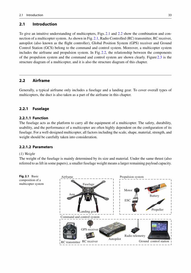
To give an intuitive understanding of multicopters, Figs. 2.1 and 2.2 show the combination and con-nection of a multicopter system. As shown in Fig. 2.1, Radio Controlled (RC) transmitter, RC receiver,autopilot (also known as the flight controller), Global Position System (GPS) receiver and GroundControl Station (GCS) belong to the command and control system. Moreover, a multicopter systemincludes the airframe and propulsion system. In Fig. 2.2, the relationship between the componentsof the propulsion system and the command and control system are shown clearly. Figure 2.3 is thestructure diagram of a multicopter, and it is also the structure diagram of this chapter.
2.2 Airframe
Generally, a typical airframe only includes a fuselage and a landing gear. To cover overall types ofmulticopters, the duct is also taken as a part of the airframe in this chapter.
2.2.1 Fuselage
2.2.1.1 FunctionThe fuselage acts as the platform to carry all the equipment of a multicopter. The safety, durability,usability, and the performance of a multicopter are often highly dependent on the configuration of itsfuselage. For a well-designed multicopter, all factors including the scale, shape, material, strength, andweight should be carefully taken into consideration.
2.2.1.2 Parameters
(1) WeightThe weight of the fuselage is mainly determined by its size and material. Under the same thrust (alsoreferred to as lift in some papers), a smaller fuselage weight means a larger remaining payload capacity.
Fig. 2.1 Basiccomposition of amulticopter system
Airframe
Battery
Propeller
Motor
ESC
Propulsion system
Fuselage
Arm
Landing gear
RC transmitter RC receiverAutopilot
GPS receiver
Radio telemetry
Ground control station
Command and control system
34 2 Basic Composition
Fig. 2.2 Combination andconnection of a multicoptersystem (photo by JethroHazelhurst from http://www.ardupilot.org)
Therefore, in the premise of ensuring the performance of the fuselage, the weight is expected to be assmall as possible.
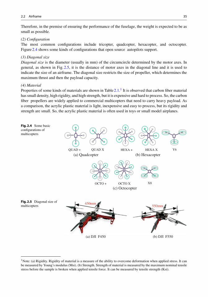
(2) ConfigurationThe most common configurations include tricopter, quadcopter, hexacopter, and octocopter.Figure 2.4 shows some kinds of configurations that open source autopilots support.
(3) Diagonal sizeDiagonal size is the diameter (usually in mm) of the circumcircle determined by the motor axes. Ingeneral, as shown in Fig. 2.5, it is the distance of motor axes in the diagonal line and it is used toindicate the size of an airframe. The diagonal size restricts the size of propeller, which determines themaximum thrust and then the payload capacity.
(4) MaterialProperties of some kinds of materials are shown in Table 2.1.1 It is observed that carbon fiber materialhas small density, high rigidity, and high strength, but it is expensive and hard to process. So, the carbonfiber propellers are widely applied to commercial multicopters that need to carry heavy payload. Asa comparison, the acrylic plastic material is light, inexpensive and easy to process, but its rigidity andstrength are small. So, the acrylic plastic material is often used in toys or small model airplanes.
Fig. 2.4 Some basicconfigurations ofmulticopters
QUAD + QUAD X HEXA + HEXA X Y6
OCTO + OCTO X X8
(a) Quadcopter (b) Hexacopter
(c) Octocopter
Fig. 2.5 Diagonal size ofmulticopters
450mm550mm
(a) DJI F450 (b) DJI F550
1Note: (a) Rigidity. Rigidity of material is a measure of the ability to overcome deformation when applied stress. It canbe measured by Young’s modulus (Msi). (b) Strength. Strength of material is measured by the maximum nominal tensilestress before the sample is broken when applied tensile force. It can be measured by tensile strength (Ksi).
Density (lb/cuin) 0.05 0.07 0.05 0.04 0.1 0.0027–0.0081
Young’s modulus(Msi)
9.3 2.7 0.75 0.38 10.3 0.16–0.9
Tensile strength(Ksi)
120 15–50 8–16 8–11 15–75 1–4.6
Cost (10:cheapest) 1 6 9 9 7 10
Producibility(10:simplest)
3 7 6 7 7 10
2.2.2 Landing Gear
Figure 2.6 shows a landing gear, functions of which include the follows:
(1) Supporting the whole multicopter when landing on the ground or taking off and keeping the levelbalance of the multicopter.
(2) Keeping propellers off ground at a safe distance.(3) Weakening ground effect (the downwash stream hits the ground and generates some disturbance
effect) when multicopters take off or land.(4) Consuming and absorbing impact energy when multicopters land on the ground.
2.2.3 Duct
2.2.3.1 FunctionIn addition to protecting the blade and ensuring personal safety, the duct can also enhance the efficiencyof thrust and reduce noise. The thrust of a multicopter with ducts is composed of two parts, i.e., thethrust of the propeller and the additional thrust induced by the duct, as shown in Fig. 2.7.
Fig. 2.6 A landing gear
2.2 Airframe 37
Fig. 2.7 Duct Thrust induced by duct
Thrust of propeller
Inlet
Diffuser
(a) Working principle (b) A quadcopter with ducts
2.2.3.2 Working PrincipleFor a rotating propeller in the duct, airflow inside the inlet flows faster than the outside, while thepressure inside is lower than the outside according to Bernoulli’s Principle, therefore an additionalthrust is obtained. Beside, varying the cross section of the duct allows the designer to advantageouslychange the speed and pressure of the airflow. In addition, by adding a duct, the loss due to the tip vortexwhich occurs when a propeller operates in free space can be reduced. Therefore, the efficiency andmaximum thrust can be increased, sometimes may be significantly.
2.2.3.3 ParametersThe diffuser length and propeller diameter are important parameters for the duct, and reader can referto [2] for its detailed optimization design method. Although the duct may improve the efficiency toincrease the hovering time, the duct itself is generally heavy which may significantly increase theweight and reduce the time. So, the final optimal design needs to achieve a trade-off.
2.3 Propulsion System
A propulsion system includes propellers, motors, ESCs, and often a battery. This system is the mostimportant part of the multicopter, which determines the main performances such as the hovering time,the payload ability, and the flying speed and distance. Moreover, components of the propulsion systemhave to be compatible with each other, otherwise they cannot work properly or even fails in someextreme cases. For example, in some conditions, an aggressive maneuver may make the current exceedthe safety threshold of the ESC, then make the motors stop working in the air, which is very dangerous.Performance evaluation of a propulsion system will be introduced in Chap. 4.
2.3.1 Propeller
2.3.1.1 FunctionPropeller is a component that produces the thrust and torque to control a multicopter. The motorefficiency varies with the output torque (depends on the type, size, speed and other factors of a propeller).Therefore, a good match should make sure that the motor works in a high efficiency condition, whichwill guarantee less power consumed for the same thrust and then extend the time of endurance of themulticopter. Therefore, choosing appropriate propellers is a very direct way to improve the performanceand efficiency of a multicopter.
(1) TypeGenerally, the propeller model is described by a four-digit number, such as a 1045 (or 10 × 45)propeller, among which the first two represents the diameter of the propeller (unit: inch), and the lattertwo represents the propeller pitch (also referred to as screw pitch, blade pitch or simplified as pitch,unit: inch). Therefore, the APC1045 propeller implies that the propeller belongs to APC series, andthe diameter and pitch of the propeller is 10 in. and 4.5 in., respectively. The propeller pitch is definedas “the distance a propeller would move in one revolution if it were moving through a soft solid,like a screw through wood.” For example, a 21-inch-pitch propeller would move forward 21 in. perrevolution.
(2) Chord lengthThe definition of chord length of a propeller is shown in Fig. 2.8, which varies along the radius.Generally, the chord located at the 2/3 of the radius of the propeller is chosen as the nominal chordlength.
(3) Moment of inertiaMoment of inertia is a quantity expressing the tendency of a body to resist angular acceleration, whichis the sum of the products of the mass of each particle in the body with the square of its distance fromthe rotation axis. A smaller moment of inertia of the propeller can improve the response speed of themotor, which is important for the control effect and performance.
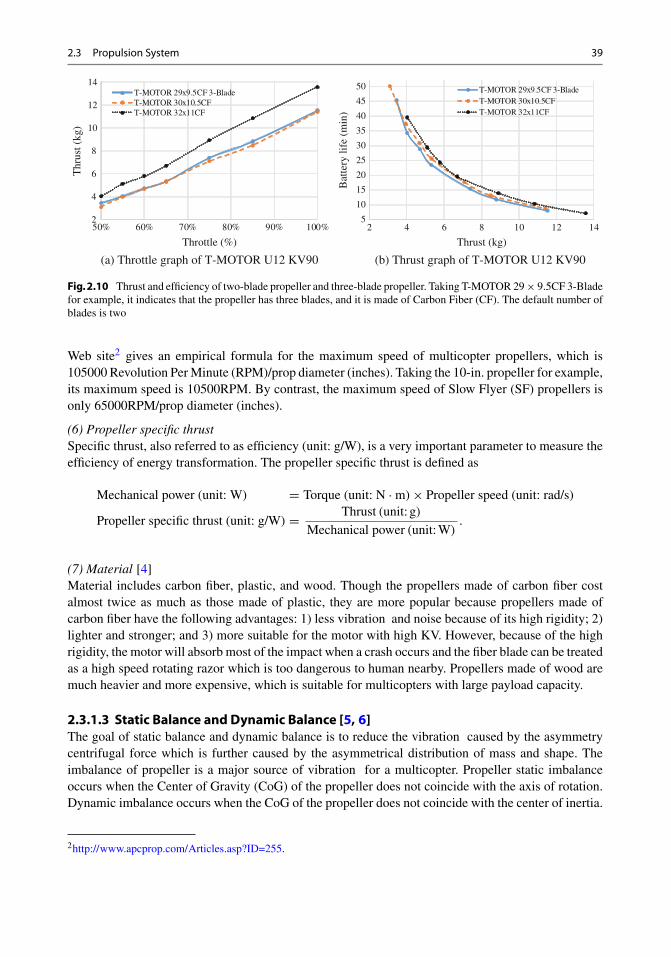
(4) Number of bladesSome typical propellers with different number of blades are shown in Fig. 2.9. Experiments indicatedthat the efficiency of two-blade propeller is better comparing with three-blade propeller [3, p. 65]. Asshown in Fig. 2.10, the maximum thrust of the propeller is increased with the number of the blades(Fig. 2.10a), while the efficiency is decreased with the number of the blades (Fig. 2.10b). It can alsobe found that, to obtain the same thrust, a three-blade propeller has a less diameter compared with thecorresponding two-blade propeller. Although the efficiency is reduced, the time of endurance may beimproved to a certain extent by the reduction of the size and weight of the airframe.
(5) Safe rotation rateGenerally, the materials of propellers used on the multicopters are flexible. So, when rotation rateexceeds a certain value, the propellers may deform, which will reduce its efficiency. Therefore, whencalculating the safety rotation rate limit, all the possible conditions should be considered. The APC
Fig. 2.8 Chord length of apropeller
Chord length
Fig. 2.9 Propellers withdifferent number of blades
Fig.2.10 Thrust and efficiency of two-blade propeller and three-blade propeller. Taking T-MOTOR 29 × 9.5CF 3-Bladefor example, it indicates that the propeller has three blades, and it is made of Carbon Fiber (CF). The default number ofblades is two
Web site2 gives an empirical formula for the maximum speed of multicopter propellers, which is105000 Revolution Per Minute (RPM)/prop diameter (inches). Taking the 10-in. propeller for example,its maximum speed is 10500RPM. By contrast, the maximum speed of Slow Flyer (SF) propellers isonly 65000RPM/prop diameter (inches).
(6) Propeller specific thrustSpecific thrust, also referred to as efficiency (unit: g/W), is a very important parameter to measure theefficiency of energy transformation. The propeller specific thrust is defined as
Mechanical power (unit: W) = Torque (unit: N · m) × Propeller speed (unit: rad/s)
Propeller specific thrust (unit: g/W) = Thrust (unit: g)Mechanical power (unit: W)
.
(7) Material [4]Material includes carbon fiber, plastic, and wood. Though the propellers made of carbon fiber costalmost twice as much as those made of plastic, they are more popular because propellers made ofcarbon fiber have the following advantages: 1) less vibration and noise because of its high rigidity; 2)lighter and stronger; and 3) more suitable for the motor with high KV. However, because of the highrigidity, the motor will absorb most of the impact when a crash occurs and the fiber blade can be treatedas a high speed rotating razor which is too dangerous to human nearby. Propellers made of wood aremuch heavier and more expensive, which is suitable for multicopters with large payload capacity.
2.3.1.3 Static Balance and Dynamic Balance [5, 6]The goal of static balance and dynamic balance is to reduce the vibration caused by the asymmetrycentrifugal force which is further caused by the asymmetrical distribution of mass and shape. Theimbalance of propeller is a major source of vibration for a multicopter. Propeller static imbalanceoccurs when the Center of Gravity (CoG) of the propeller does not coincide with the axis of rotation.Dynamic imbalance occurs when the CoG of the propeller does not coincide with the center of inertia.
The imbalanced force not only affects the sensor measurement, but also makes the motor bearingwear down more quickly and increases the power consumption. These characteristics will shorten thelifetime of multicopters and increase the possibility of failure. Besides, an imbalanced propeller is farnoisier than a balanced one. A balancer as shown in the Fig. 2.11 can be used to test the static balanceof a propeller. The test of dynamic balance is often not an easy work as it needs sensors to recordthe data. An easy way without using sensors is introduced in a video [7]. If imbalance exists, somemeasures can be taken, such as pasting scotch tapes on the lighter blade or grinding the heavier one(not the edge) using sandpapers.
2.3.2 Motor [8,pp.533–592]
2.3.2.1 FunctionMotors of multicopters are mainly brushless DC motors for the various advantages such as highefficiency, potential to downsize, and low manufacturing costs. Brushless DC motors are used toconvert electrical energy (stored in battery) into mechanical energy for propeller. Concretely, basedon the position of rotors, brushless DC motors can be classified into the outer rotor type and innerrotor type as shown in Fig. 2.12. Considering that the motor of a multicopter is supposed to drive largerpropellers to improve efficiency, the outer rotor type outperforms the inner rotor type as it can providelarger torques. Besides, compared with the inner rotor type, speed of the outer rotor type is more stable.Therefore, the outer rotor type is more popular in multicopters and most other aircraft.
2.3.2.2 Working PrincipleAs shown in Fig. 2.13, the control circuit generates a Pulse Width Modulated (PWM) signal to theESC, where the signal is amplified by a driving circuit and sent to the power switch of the inverter.Then, it will control the motor winding to work in a certain sequence and generate a jump-type rotatingmagnetic field in the air gap of the motor. Common types of main circuits of brushless DC motorsinclude the star-type three-phase half-bridge, star-type three-phase bridge, and angle-type three-phasebridge. Among them, the star-type three-phase bridge is used most widely. Three output signals ofthe position detector are controlled by a logic circuit to control the on and off states of the switch.There are two control modes: two-two conduction mode and three-three conduction mode. As shown
2.3 Propulsion System 41
Fig. 2.12 Outer rotor typeand inner rotor type (photocourtesy of www.nidec.com)
(a) Inner rotor type (b) Outer rotor type
Hall IC detects rotor
Rotor
Motor case
BearingPermanent magnet
Winding
Stator
Hall element detects
Rotor
Motor case
Bearing
Permanent magnet
Winding
Stator
Fig. 2.13 Main circuit ofstar-type three-phasebridge
U m
D1 D3 D5
D4 D6 D2
A
B
C
+
-
Fig. 2.14 Counterelectromotive forcewaveform of three-phasewinding and its two-twoconduction mode
0 9 0 2 1 0 3 3 0 4 5 0 5 7 0 6 9 0
u a
u b
u c
D 1 D 1
D 4 D 4
D 3 D 3
D 6 D 6
D 5
D 2 D 2
D 6
D 5
in Fig. 2.14, every 60◦ the rotor rotates, the switches of inverters commutate one time and the field ofthe state of stator changes one time. There are six magnetic states and three phases for motors, eachphase conducts 120◦.
(1) SizeSize of motor is generally represented by its stator size with four-digit number, such as motor 2212 (orwritten as 22 × 12), among which the first two indicates its stator diameter (mm) and the latter twoindicates its stator height (mm). For example, the motor 2212 indicates that the stator diameter of themotor is 22 mm and the stator height is 12 mm. That means, the larger the former two are, the wider themotor is; the larger the latter two are, the higher the motor is. A wide and high motor has high power,which is more suitable for large multicopters.
(2) KV value for motorsThe KV value for brushless DC motors is the number of RPM that the motor will revolve when 1 V(Volt) is applied with no load attached to the motor. For example, 1000 KV just means that when 1 Vis applied, the no-load motor speed will be 1000 RPM. A low KV motor has more windings of thinnerwire, which means it will carry more power, produce a higher torque, and drive a bigger propeller. Bycontrast, a high KV motor can produce a low torque so that it can only drive a small propeller.
(3) No-load current and voltageIn the no-load test, the current passing through the three-phase winding of stator after applying nominalvoltage (generally 10 or 24 V) is defined as the nominal no-load current.
(4) Maximum current/powerIt is the maximum current or power the motor can undertake. For example, maximum continuouscurrent “25A/30s” represents that the motor can work safely with continuous current up to 25A,beyond which for more than 30s the motor may be burnt out. The same definition can be applied forthe maximum continuous power.
(5) ResistanceThere is resistance in all motor armatures. It is very small but cannot be ignored because the currentflowing through the resistance is tremendously large and sometimes reaches tens of Amperes. Theexistence of the resistance generates heat during the running of the motor, which may overheat themotor and reduce the efficiency.
(6) Motor efficiencyMotor efficiency is an important parameter to measure the performance. It is defined as follows:
Electrical power (unit: W) = Input Voltage (unit: V) × Effective current (unit: A)
Motor efficiency = Mechanical power (unit: W)
Electrical power (unit: W).
The motor efficiency is not a constant. In general, it varies with input voltage (throttle) and load(propeller). For the same propeller, the efficiency of the motor may be reduced as the input voltage(current) is increased. That is because the larger the current is, the more the heat (caused by theresistance) and other loss will be, which makes the ratio of the effective mechanical power reduced.
(7) Overall specific thrustThe overall performance of the propulsion system depends largely on a well-matched combination ofmotor and propeller. To evaluate the efficiency of the motor and propeller together, the overall specificthrust is calculated as
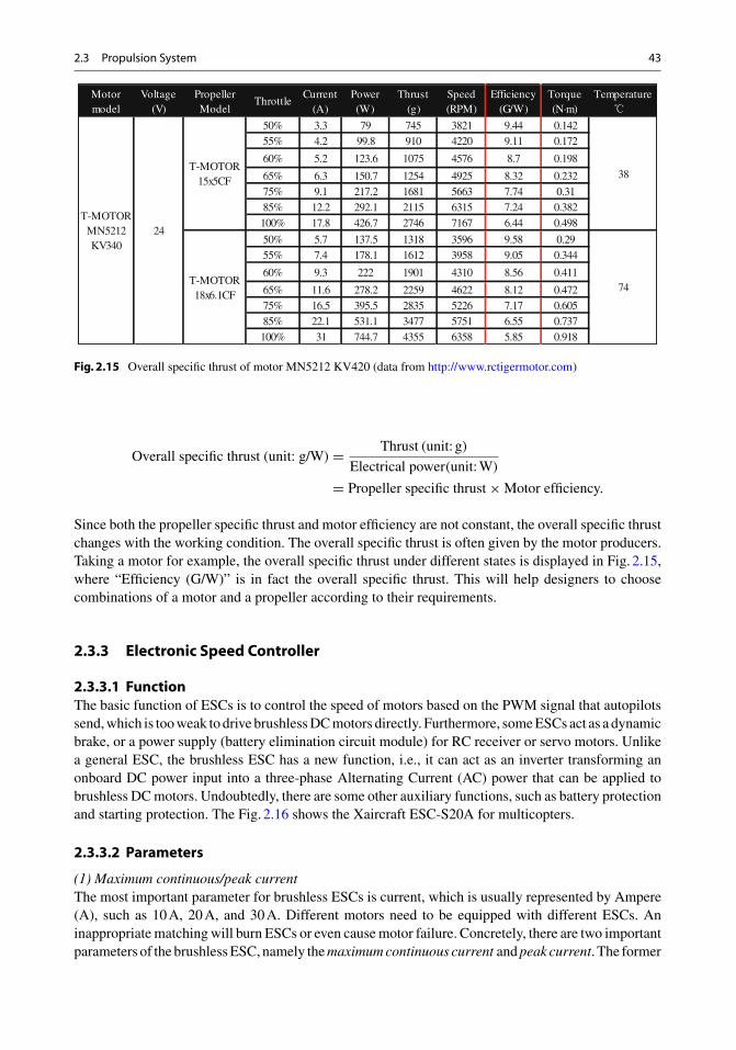
Fig. 2.15 Overall specific thrust of motor MN5212 KV420 (data from http://www.rctigermotor.com)
Overall specific thrust (unit: g/W) = Thrust (unit: g)
Electrical power(unit: W)
= Propeller specific thrust × Motor efficiency.
Since both the propeller specific thrust and motor efficiency are not constant, the overall specific thrustchanges with the working condition. The overall specific thrust is often given by the motor producers.Taking a motor for example, the overall specific thrust under different states is displayed in Fig. 2.15,where “Efficiency (G/W)” is in fact the overall specific thrust. This will help designers to choosecombinations of a motor and a propeller according to their requirements.
2.3.3 Electronic Speed Controller
2.3.3.1 FunctionThe basic function of ESCs is to control the speed of motors based on the PWM signal that autopilotssend, which is too weak to drive brushless DC motors directly. Furthermore, some ESCs act as a dynamicbrake, or a power supply (battery elimination circuit module) for RC receiver or servo motors. Unlikea general ESC, the brushless ESC has a new function, i.e., it can act as an inverter transforming anonboard DC power input into a three-phase Alternating Current (AC) power that can be applied tobrushless DC motors. Undoubtedly, there are some other auxiliary functions, such as battery protectionand starting protection. The Fig. 2.16 shows the Xaircraft ESC-S20A for multicopters.
2.3.3.2 Parameters
(1) Maximum continuous/peak currentThe most important parameter for brushless ESCs is current, which is usually represented by Ampere(A), such as 10 A, 20 A, and 30 A. Different motors need to be equipped with different ESCs. Aninappropriate matching will burn ESCs or even cause motor failure. Concretely, there are two importantparameters of the brushless ESC, namely the maximum continuous current and peak current. The former
is the maximum continuous current in the normal working condition, while the latter is the maximuminstantaneous current that the ESC can withstand. Each ESC will be labeled with a specified value,such as Hobbywing XRotor 15 A which indicates the maximum continuous current allowed. Whenchoosing the type of ESCs, attention should be paid to the maximum continuous current, which needsto be checked whether it leaves a safety margin (20% for example) so as to efficiently avoid burningthe power tube. Taking 50A ESC for example, 10A is often left as a safety margin.
(2) Voltage rangeThe range of voltage allowing the ESC to work properly is also an important parameter. Usually, theindex like “3-4S LiPo” can be found on the ESC specification, which means that the voltage range ofthis ESC is 3-4 cells of LiPo battery, i.e., 11.1–14.8 V.
(3) ResistanceSince all ESCs have resistance, the heating power cannot be ignored because the current flowingthrough them can sometimes reach tens of Amperes. Considering the heat dissipation, the resistanceof ESCs with high current is always designed to be small.
(4) Refresh rateThe motor response has a great relationship with the refresh rate of ESCs. Before the development ofmulticopters, ESCs were designed specifically for model airplanes or cars. The maximum operatingfrequency of servo motors was 50 Hz, therefore the refresh rate of ESCs was 50 Hz. Theoretically, thehigher the refresh rate is, the faster the response will be. Since multicopters differ from other types ofmodel airplanes in that the rapid thrust adjustment is realized by the rapid control of propeller angularspeed, the refresh rate of multicopter ESCs is often faster. In order to ensure smooth outputs, low-passfiltering is often applied to the input or output of ESCs at the cost of reducing their response rate. Thisalso implies the reduced control frequency.
(5) ProgrammabilityThe performance of ESCs can be optimized by tuning internal parameters. There are three ways toset the parameters of ESCs, i.e., programmable cards as shown in Fig. 2.17, computer software via theUSB, and RC transmitters. The parameters that can be set up include: throttle range calibration, lowvoltage protection, power outage value, current limitation, brakes mode, throttle control mode, switchtiming setting, starting mode, and PWM mode setting.
(6) CompatibilityIf the ESC and motor are incompatible, the motor is likely to be jammed, which may result in a falland crash for a multicopter in the air. Sometimes motors may get jammed in extreme cases, such as thecase that the control command for mode transitions changes sharply, generating large instantaneouscurrent, which are not easy to be detected.
2.3.3.3 Square-Wave Driver and Sinusoidal Driver [9]
(1) Square-wave driverSquare-wave driver type ESC outputs square wave. Its control elements work in the switch state, whichmakes it simpler, cheaper, and easier to control.
(2) Sinusoidal driverSinusoidal driver-type ESC outputs sinusoidal wave, which uses Field Oriented Control (FOC). There-fore the sinusoidal driver performs better in the aspects of operation stability, speed range, efficiency,and vibration reduction of noise. Now, the optical encoder, Hall sensor and observer-based method areavailable to measure the angle of the rotor. For a multicopter, its motor rotors are working in a highspeed state, which means the FOC can be applied based on the observation of rotor electrical anglewith information including the motor model, current, and voltage. This is a good way to reduce thecost.
2.3.4 Battery
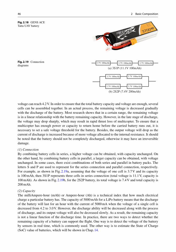
2.3.4.1 FunctionBattery is used to provide energy. A battery for small multicopters is shown in Fig. 2.18. A problem oftenconcerned on present multicopters is the time of endurance , which heavily depends on the capacity ofbatteries. Now, there are many types of batteries, where the Lithium Polymer (LiPo) battery and NickelMetal Hydride (NiMH) battery are the most commonly used ones because of superior performanceand cheap price.
2.3.4.2 ParametersThe basic parameters of the battery include voltage, discharge capacity, internal resistance, and dis-charge rate. The nominal voltage of a single cell of LiPo battery is 3.7 V. When it is fully charged, the
46 2 Basic Composition
Fig. 2.18 GENS ACETattu UAV battery
Fig. 2.19 Connectiondiagrams
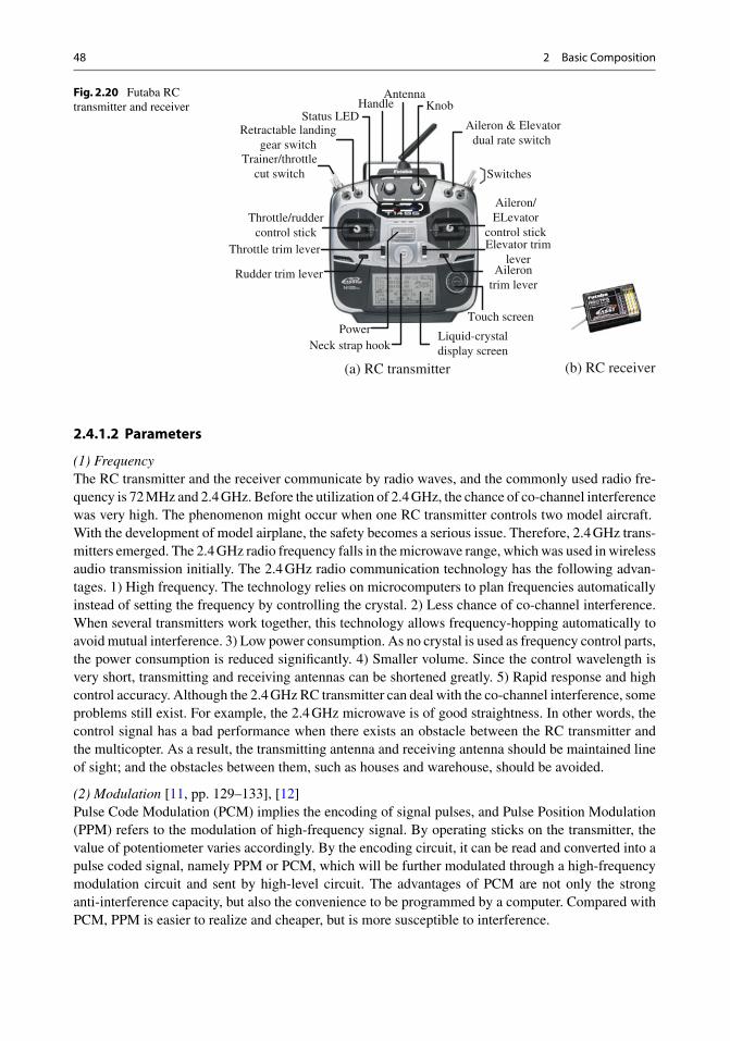
3.7V 100mAh 3.7V 100mAh 3.7V 100mAh
3.7V 100mAh 3.7V 100mAh
3.7V 100mAh 3.7V 100mAh
(a) 3S1P (11.1V 100mAh)
(b) 2S2P (7.4V 200mAh)
voltage can reach 4.2 V. In order to ensure that the total battery capacity and voltage are enough, severalcells can be assembled together. In an actual process, the remaining voltage is decreased graduallywith the discharge of the battery. Most research shows that in a certain range, the remaining voltageis in a linear relationship with the battery remaining capacity. However, in the late stage of discharge,the voltage may drop sharply, which may result in rapid thrust loss of multicopter. To ensure that amulticopter has enough power or capacity to return home before the carried battery runs out, it isnecessary to set a safe voltage threshold for the battery. Besides, the output voltage will drop as thecurrent of discharge is increased because of more voltage allocated to the internal resistance. It shouldbe noted that the battery should not be completely discharged, otherwise it may have an irreversibledamage.
(1) ConnectionBy combining battery cells in series, a higher voltage can be obtained, with capacity unchanged. Onthe other hand, by combining battery cells in parallel, a larger capacity can be obtained, with voltageunchanged. In some cases, there exist combinations of both series and parallel in battery packs. Theletters S and P are used to represent for the series connection and parallel connection, respectively.For example, as shown in Fig. 2.19a, assuming that the voltage of one cell is 3.7 V and its capacityis 100 mAh, then 3S1P represents three cells in series connection (total voltage is 11.1 V, capacity is100 mAh). As shown in Fig. 2.19b, for the 2S2P battery, its total voltage is 7.4 V and total capacity is200 mAh.
(2) CapacityThe milliAmpere-hour (mAh) or Ampere-hour (Ah) is a technical index that how much electricalcharge a particular battery has. The capacity of 5000 mAh for a LiPo battery means that the dischargeof the battery will last for an hour with the current of 5000 mA when the voltage of a single cell isdecreased from 4.2 to 3.0 V. However, the discharge ability will be decreased along with the processof discharge, and its output voltage will also be decreased slowly. As a result, the remaining capacityis not a linear function of the discharge time. In practice, there are two ways to detect whether theremaining capacity of a battery can support the flight. One way is to detect the voltage of the batteryby sensors in real time, which is commonly used. The other way is to estimate the State of Charge(SoC) value of batteries, which will be shown in Chap. 14.
(3) Discharge RateDischarge rate is represented by
Discharge Rate (unit: C) = Current of Discharge (unit: mA)
Capacity (unit: mAh).
For example, the discharge rate of a battery will be 0.2 C when its nominal capacity is 100 mAh andthe discharge current is 20 mA. Obviously, the discharge rate measures the rate of discharge. When themaximum discharge rate of a battery with the nominal capacity of 5000 mAh is 20C, the maximumcurrent of discharge is calculated as 5000 mA × 20C = 100 A. The total current of a multicoptercannot exceed its maximum current limit of the battery; otherwise, the battery may be burnt out. Thebattery having higher discharge rate can generate more current, which can be applied to multicoptersdemanding higher current because of heavier bodies and more motors.
(4) ResistanceResistance of a battery is not a constant value, and it varies with the power status and service life.The resistance of a rechargeable battery is relatively small in the initial state. However, after a longperiod of use, because of the exhaustion of electrolyte and decrease in chemical substance activity ofthe battery, the internal resistance will be increased gradually until to a certain degree where the powerin the battery cannot be released. Then, the battery can be regarded as being run out of.
(5) Energy DensityEnergy density is the amount of energy stored in a given system or region of space per unit volume ormass, and the latter is more accurately termed specific energy. In general, the units for energy densityand specific energy are (Watt × hour)/kg and (Watt × hour)/L, i.e., Wh/kg and Wh/L, respectively.Batteries with higher energy density are more popular due to the contradiction between volume (weight)and endurance for a product. Lithium-ion battery as a kind of clean energy is getting more and moreattentions and is widely used in many applications. The energy density of Lithium-ion batteries variesfrom chemistry to chemistry and the energy density can range from 240 to 300 Wh/L (double of theNiCd, 1.5 times of NiMH).
2.4 Command and Control System
2.4.1 RCTransmitter and Receiver [10]
2.4.1.1 FunctionAn RC transmitter, as shown in Fig. 2.20a,3 is used to transmit commands from remote pilots to thecorresponding receiver. Then, the receiver, as shown in Fig. 2.20b, passes the commands to the autopilotafter decoding them. Finally, the multicopter flies according to the commands. Some flight parameterscan be set on the transmitter, such as the throttle direction, stick sensitivity, neutral position of RC servomotors, function definitions of channels, record and remind setting of flight time, and lever functionsetting. Advanced functions include battery voltage and current flight data of multicopters. At present,there are several open source transmitters. Readers interested in detailed information can refer to theWeb site http://www.open-tx.org or http://www.reseau.org/arduinorc, based on which transmitters canbe customized.
3For a multicopter, the throttle control stick is to control the upward-and-downward movement, and the rudder controlstick is to control the yaw movement, while the aileron stick is to control the roll movement, and the elevator stick is tocontrol the pitch movement.
(1) FrequencyThe RC transmitter and the receiver communicate by radio waves, and the commonly used radio fre-quency is 72 MHz and 2.4 GHz. Before the utilization of 2.4 GHz, the chance of co-channel interferencewas very high. The phenomenon might occur when one RC transmitter controls two model aircraft.With the development of model airplane, the safety becomes a serious issue. Therefore, 2.4 GHz trans-mitters emerged. The 2.4 GHz radio frequency falls in the microwave range, which was used in wirelessaudio transmission initially. The 2.4 GHz radio communication technology has the following advan-tages. 1) High frequency. The technology relies on microcomputers to plan frequencies automaticallyinstead of setting the frequency by controlling the crystal. 2) Less chance of co-channel interference.When several transmitters work together, this technology allows frequency-hopping automatically toavoid mutual interference. 3) Low power consumption. As no crystal is used as frequency control parts,the power consumption is reduced significantly. 4) Smaller volume. Since the control wavelength isvery short, transmitting and receiving antennas can be shortened greatly. 5) Rapid response and highcontrol accuracy. Although the 2.4 GHz RC transmitter can deal with the co-channel interference, someproblems still exist. For example, the 2.4 GHz microwave is of good straightness. In other words, thecontrol signal has a bad performance when there exists an obstacle between the RC transmitter andthe multicopter. As a result, the transmitting antenna and receiving antenna should be maintained lineof sight; and the obstacles between them, such as houses and warehouse, should be avoided.
(2) Modulation [11, pp. 129–133], [12]Pulse Code Modulation (PCM) implies the encoding of signal pulses, and Pulse Position Modulation(PPM) refers to the modulation of high-frequency signal. By operating sticks on the transmitter, thevalue of potentiometer varies accordingly. By the encoding circuit, it can be read and converted into apulse coded signal, namely PPM or PCM, which will be further modulated through a high-frequencymodulation circuit and sent by high-level circuit. The advantages of PCM are not only the stronganti-interference capacity, but also the convenience to be programmed by a computer. Compared withPCM, PPM is easier to realize and cheaper, but is more susceptible to interference.
2.4 Command and Control System 49
(3) ChannelsOne channel corresponds to one separate operation, and generally there are six-channel transmitters,eight-channel transmitters, and ten-channel (or more) transmitters to control multicopters. The opera-tions needed include: throttle control, yaw control, pitch control, and roll control. In this way, an RCtransmitter requires four channels at least. Considering the mode transition and control of cameragimbal, transmitters with at least eight channels are recommended.
(4) Mode [13]RC transmitter modes refer to the way how an RC transmitter is configured to control a multicopter,i.e., the relationship that sticks correspond to movements. For example shown in Fig. 2.21, “Mode 1”:pitch/yaw on the left stick, throttle/roll on the right (also called right-hand mode, popular in Japan,more suitable for fixed-wing aircraft); “Mode 2”: throttle/yaw on the left, pitch/roll on the right (alsocalled left-hand mode, popular in the U.S. and other parts of the world including China, more suitablefor multicopters).
(5) ThrottleIn general, the throttle control stick in an RC transmitter is designed to be unable to recover back toits original position automatically. The direct-type RC transmitter in this book refers to the type thatthe total thrust has a positive correlation with the deflection of the throttle control stick. Furthermore,a connected motor will stop with the throttle control stick at the bottom and work at a full speed withthe throttle control stick at the top. The transmitter can also be set to recover back to the midpointautomatically once it is released, which is called the increment-type RC transmitter in this book. Corre-spondingly, the motor speed will be increased when the stick is higher than the midpoint and decreasedwhen lower than the midpoint. The mode transition can be realized by loosening and tightening thespring washers behind the stick and then using specified algorithms.
(6) Remote control distanceThe control distance of an RC transmitter is restricted by its power. For example, the effective controldistance of the “Md-200” is claimed to be 1000 m. In order to extend the control distance, poweramplifiers and antennas can be used.
Mode 2
Throttle
Yaw
Pitch
Roll
Mode 1
Pitch
Yaw
Throttle
Roll
For multicopters For fixed-wing aircraftThrottle : control the upward-and-downward movement corresponding to the throttle stick Pitch : control the forward-and-backward movement corresponding to the elevatorYaw : control the yaw movement corresponding to the rudderRoll : control the leftward-and-rightward movement corresponding to the aileron
Fig. 2.21 Different control modes of an RC transmitter
50 2 Basic Composition
2.4.2 Autopilot
A multicopter autopilot is a flight control system used to control the attitude, position, and trajectory ofa multicopter. It can be semi-automatically (needs commands from remote pilot) or fully automatically.Autopilots have a control framework which is often based on Proportional-Integral-Derivative (PID)controllers, leaving parameters to be tuned for different multicopters.
2.4.2.1 CompositionA multicopter autopilot can be divided into the software part and hardware part. The software partis the brain of a multicopter and it is used to process and send information, while the hardware partgenerally includes the following components:
(1) GPS receiver. It is used to obtain the location information of multicopters.(2) Inertial Measurement Unit (IMU). It includes: the three-axis accelerometer, three-axis gyroscope,
and electronic compass (or three-axis magnetometer). It is used to obtain attitude information ofa multicopter. In general, a six-axis IMU is the combination of a three-axis accelerometer and athree-axis gyroscope; a nine-axis IMU is the combination of a three-axis accelerometer, a three-axis gyroscope and a three-axis magnetometer; and a ten-axis is the combination of a nine-axisIMU and a barometer.
(3) Height sensor. The barometer and ultrasonic range finder are used to obtain the absolute height(altitude) and relative height (distance to the ground), respectively.
(4) Microcomputers. It acts as a platform to receive information and run algorithms to produce controlcommand.
(5) Interface. It acts as a bridge between the microcomputer and the other devices, such as the sensors,ESC, and RC receiver.
2.4.2.2 Function(1) Perception. It is used to solve the problem of “where the multicopter is.” The GPS receiver, IMU,
and height sensors all have a lot of noises, and their refresh rates are not the same. For example,the refresh rate of a GPS receiver is 5 Hz, while the refresh rate of an accelerometer may be1000 Hz. One task of an autopilot is to fuse these information together to obtain accurate positionand attitude. This mainly corresponds to Chaps. 7–9 in this book.
(2) Control. Control is to solve the problem of “how the multicopter flies to a desired position.” Basedon the position and attitude measured and given, the low-level flight control law is carried out,generating commands for ESCs to control the motors of a multicopter to achieve a desired position.This mainly corresponds to Chaps. 10–12 in this book.
(3) Decision. Decision is to solve the problem of “where the multicopter will go.” The decision-making mainly includes the mission decision-making and failsafe. This mainly corresponds toChaps. 13 and 14 in this book.
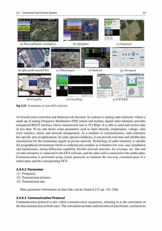
2.4.2.3 Open Source AutopilotCurrently, there are many free open source autopilots of multicopters. The Web sites can be found fromTable 1.3 in Chap. 1. Open source autopilot flight control boards (hardware) are shown in Fig. 2.22.The types and performance of components of some autopilots are shown in Table 2.2.
2.4.3.1 FunctionAn important part of a GCS is the software. Remote pilots can interact with the software using themouse, keyboard, button, and joystick. So, way points can be planned by remote pilots for multicoptersin advance. Furthermore, remote pilots can monitor the flight status in real time and set new missionsto intervene flight. Besides, the software can record and playback flight for analysis.
2.4.3.2 Open Source GCS SoftwareThere are a lot of free open source GCS software available for multicopters now. Figure 2.23 shows somescreenshots of GCS software. Most of the GCS software can be downloaded from the correspondingautopilot Web sites, which are listed on the Table 1.3.
2.4.4 Radio Telemetry
2.4.4.1 FunctionRadio telemetry refers to using Digital Signal Processing (DSP) technology, digital modulation anddemodulation, radio technology to transmit data with high accuracy, and it is equipped with functions
of forward error correction and balanced soft decision. In contrast to analog radio telemetry which ismade up of analog Frequency Modulation (FM) station and modem, digital radio telemetry providestransparent RS232 interface whose transmission rate is 19.2 Kbps. It is able to send and receive datain less than 10 ms and shows some parameters such as field intensity, temperature, voltage, stateerror statistics, alarm, and network management. As a medium of communication, radio telemetryhas specific area of applications. In some special conditions, it can provide real-time and reliable datatransmission for the monitoring signals in private network. Technology of radio telemetry is suitablefor geographical environment which is scattered and complex as it features low cost, easy installationand maintenance, strong diffraction capability, flexible network structure, far coverage, etc. One endof radio telemetry is connected to the GCS software, and the other end is connected to the multicopter.Communication is performed using certain protocols to maintain the two-way communication of amulticopter and the corresponding GCS.
More parameter information on data links can be found in [15, pp. 191–246].
2.4.4.3 Communication ProtocolCommunication protocol is also called communication regulations, referring to as the convention ofthe data transmission on both sides. The convention includes uniform rules of data format, synchronous
54 2 Basic Composition
method, transmission rate, procedure, error checking, and correct on and definition of control characters,which should be recorded by both sides of communication. It is also called link control regulations.The formulation of communication protocol is advantageous to the separation of GCS and autopilot.As long as communication protocols are obeyed, the GCS software can be compatible with differentautopilots.
MAVLink communication protocol is a library organization which only has the header files andit is designed for micro and small aircraft. It is on the basis of the GNU (GNU’s Not Unix) LesserGeneral Public License (LGPL) and MAVLink can efficiently encapsulate C-data structure through aserial port, and send the data packet to the GCS. This communication protocol is widely tested byPX4 , APM, and Parrot AR. Drone. There are other protocols. For example, Openpilot autopilot adoptsUAVTalk protocol to communicate with GCS.
2.5 Summary
As the Chinese idiom says, “small as the sparrow is, it possesses all its internal organs (small, butcomplete!).” This proverb is also applicable to a multicopter. This chapter introduces each componentof a multicopter mainly in the aspects of function and key parameters. The composition of a multicopterintroduced above can support the fully-autonomous flight of a multicopter. For the multicopter underthe Semi-Autonomous Control (SAC) mode, some components can be removed, such as GCS and GPSreceiver. In order to choose better components and improve the performance or find out the causes offailure, it is necessary to have a deep and comprehensive understanding of multicopters. For example,by adjusting the ESC parameters and choosing appropriate propellers, the flight performance can beimproved; by considering the compatibility of ESCs and motors in advance, some crashes can beavoided.
Exercises
2.1 Find a multicopter with the airframe, propeller, ESC, motor, battery, and then explain the meaningof the key parameters of each component in detail.
2.2 Give a method of checking propeller dynamic balance.
2.3 Explain the principle of ESC with sinusoidal driver.
2.4 Choose and compare two autopilots, then clarify their advantages and disadvantages.
2.5 In order to combine the advantage of airplanes and multicopters, there are some kinds of aircraftable to take off and land vertically being available online. Find out a product and analyze its flightprinciple, advantages and disadvantages.
References
1. Frame materials. http://aeroquad.com/showwiki.php?title=Frame-Materials. Accessed 7 Apr 20162. Hrishikeshavan V, Black J, Chopra I (2014) Design and performance of a quad-shrouded rotor micro air vehicle.
3. Harrington AM (2011) Optimal propulsion system design for a micro quad rotor. Dissertation, University of Mary-land
4. RC airplane propellers. http://www.rc-airplanes-simplified.com/rc-airplane-propellers.html. Accessed 29 Jan 20165. MacCamhaoil M (2012) Static and dynamic balancing of rigid rotors. Bruel & Kjaer application notes, BO: 0276–126. Wijerathne C (2015) Propeller balancing. http://okigihan.blogspot.com/p/propellerbalancing-propeller-unbalance.
html. Accessed 29 Jan 20167. Laser balancing props. http://flitetest.com/articles/Laser_Balancing_Props. Accessed 29 Jan 20168. Chapman SJ (2005) Electric machinery fundamentals, 4th edn. McGraw-Hill Higher Education, Boston9. Bertoluzzo M, Buja G, Keshri RK et al (2015) Sinusoidal versus square-wave current supply of PM brushless DC
drives: a convenience analysis. IEEE Trans Ind Electron 62:7339–734910. Büchi R (2014) Radio control with 2.4 GHz. BoD–Books on Demand11. Norris D (2014) Build your own quadcopter. McGraw-Hill Education, New York12. Rother P (2000) PCM or PPM? Possibilities, performance? http://www.aerodesign.de/peter/2000/PCM/PCM_
PPM_eng.html. Accessed 29 Jan 201613. RC transmitter modes for airplanes. http://www.rc-airplane-world.com/rc-transmitter-modes.html. Accessed 29
Jan 201614. Lim H, Park J, Lee D et al (2012) Build your own quadrotor: open-source projects on unmanned aerial vehicles.
IEEE Robot Autom Mag 19:33–4515. Fahlstrom P, Gleason T (2012) Introduction to UAV systems, 4th edn. Wiley, UK


![Laser-Odometrie für autonome Multicopter · MulticopterbietenhiereineschnelleDynamik,sindäußerstkostengünstigundwerdeninnaher ZukunftindiesenBereichenstärkerzumEinsatzkommen[9].](https://static.documents.pub/doc/80x56/5e106a1dd808077bf04199c5/laser-odometrie-fr-autonome-multicopterbietenhiereineschnelledynamiksinduerstkostengnstigundwerdeninnaher.jpg)


![Basic Multicopter Control with Inertial Sensors - IJCEM · Basic Multicopter Control with Inertial Sensors ... Arduino Uno is shown in figure. ... Arduino Playground - MPU-6050 [8]](https://static.documents.pub/doc/80x56/5b43597e7f8b9a26268be146/basic-multicopter-control-with-inertial-sensors-basic-multicopter-control.jpg)


