32
Basics of Paralleling © 2017 Cummins All Rights Reserved Revised: February 1, 2017

Basics of Paralleling
© 2017 Cummins All Rights Reserved
Revised: February 1, 2017

Course Objectives
Participants will be able to:
– Discuss basic paralleling control functions to gain a better understanding of
how paralleling is accomplished
– Explain the advantages of paralleling to enhance the overall system
reliability, performance and flexibility
– Describe how generator set control functions are provided in a distributed
logic architecture to improve paralleling reliability
– Recognize the common building blocks of a backup power system and
their functionalities

CnHm
T, w
EL

Generator Set
Skid
Engine
Alternator
Cooling
Control

Power System
Backup Power
Switchgear Transfer Switches
Utility
Loads

Paralleling
Synchronous operation of two or more generator sets connected together
on a paralleling bus in order to provide power to common loads
Paralleling Switchgear Loads

Paralleling Operation
Generators can be connected to a power plant or another generator source
only when the following conditions are met:
– Waveform
– Phase Sequence
– Speed difference (frequency)
– Phase angle difference
– Voltage amplitude difference
900 180 270 360
Øv
Deg
Source-1
Source-2
t10 t2 t3 t4
v
t
∆V
f1
t10 t2 t3 t4
v
t
f2
A
B CACB
120°120°
A
C BABC
120°120°
Sine
Square
Sawtooth

Synchronization
Synchronization is the mechanism of matching frequency, phase and voltage
of AC power sources
Maintains generator output voltageAutomatic Voltage
Regulator
Maintains engine output speedElectronic
Governor

Electronic Governor (GOV)
Fuel Tank
Pump
T, w
InjectorsSpeed Sensor
Fuel
Electronic
Governor

Automatic Voltage Regulator (AVR)
The output voltage can be
increased or decreased by altering
the strength of the magnetic field
𝜵 × 𝑬 = −𝛿𝑩
𝛿𝑡(𝐹𝑎𝑟𝑎𝑑𝑎𝑦′𝑠 𝐿𝑎𝑤)
Main RotorMain Rotor
AVR
v
t0
DC Current
Output
Magnetic
Flux FieldMain Stator
Exciter Rotor
& Stator
Rectifier

Match Frequency, Phase and Voltage
Synchronizer
CBCBClose signal
Offset
-+Load Side Line Side
Offset
Closed feedback loop:
Hz, Ø & V
Generator Set Control
Synchronizer
Sense line & load
waves:
Frequency Hz
Phase ØVoltage V
AC Network:
480 VAC, 60 Hz, 3Ø
Voltage
Regulator
Electronic
Governor
Hz, Ø
V
Synchronized
Line Side Wave
Load Side Wave

f2
f1
Synchronizing: Phase and Frequency
Adjusting the governor fuel set point
900 270
Ø
v
v
Deg180 360
t10 t2 t3
t4 t
Source-1
Source-2
Speed
Sensor
Prime
Mover
Shaft
-+
Setpoint
1800 RPM ω(t)
Fuel
Actuator
Electronic
Governor
Fuel
+
Offset (t)

Synchronizing: Voltage Amplitude
Adjusting the field excitation
v
t0
Source-1
Source-2
Voltage
Sensor
+-+
Electric
Generator
Setpoint
4.16kV
Excitation
System
Voltage
Regulator
OutputV(t)
Offset (t)

Rotor Position and Output Voltage
ElectricalDegrees = P/2 * MechanicalDegrees P: Number of poles
Main Stator Coils in SlotsAir Gap
SHAFT
S
S
NN900 180 270 360 90 180 270 360
Alternator Shaft Position
(Degrees)
One Wave Cycle
Deg
v

Controlling Speed, Phase and Voltage
Voltage
Sensor
+-+
Speed
Sensor
Prime
MoverElectric
Generator
Generator Set
Shaft
-+
Output
Setpoint
1800 RPMSetpoint
4.16kVω(t)
Excitation
System
Voltage
Regulator
Fuel
Actuator
Electronic
Governor
Fuel
Offset Offset
+

Standby System Simulation: Isolated Bus

Paralleling Sequence of Operation: Isolated Bus
Remote Start
Sync Check
Conditions Met
Engine Cranks & Builds Up
To Rated Speed & Voltage
Gen
Bus Status
Ready to Load
De-energizedFirst Start
Arbitration
EnergizedSynchronize
Close Generator Breaker
& Load Share
First Start
Permission Won

The proportional division of the kW and kVAR total load between multiple
generator sets in a paralleled system
– Load sharing is essential to avoid overloading and stability problems on the generator sets
Load share can be Isochronous or Droop
Load Sharing
2MW Load
2 MW
1 MW
1 MW
0.5 MW
1 MW
0.5 MW

The kW load sharing is achieved by increasing or decreasing fuel to the
engines
The kVAR load sharing is achieved by increasing or decreasing the field
excitation to the alternators
50% kVAR 50% kVAR 50% kVAR
kVAR
Load Share Lines
AVR AVR AVR
50% kW 50% kW50% kW
kW
Load Share Lines
GOV GOV GOV
Load Sharing
Communication
Wires
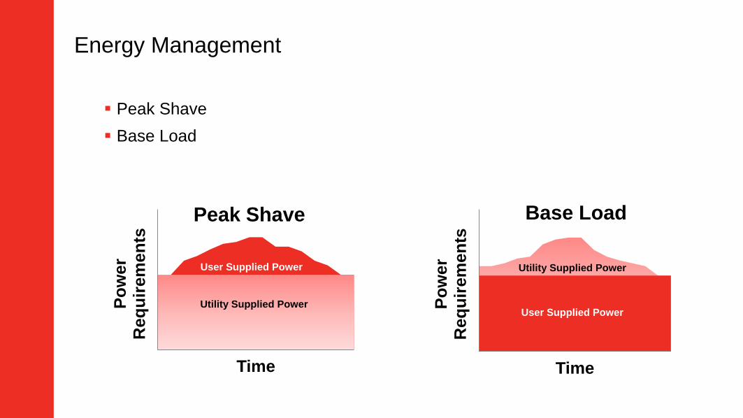
Energy Management
Po
wer
Req
uir
em
en
ts
Time
Peak Shave
Utility Supplied Power
User Supplied Power
Peak Shave
Base Load
Po
wer
Req
uir
em
en
ts
Time
Base Load
Utility Supplied Power
User Supplied Power

Connecting to the Grid
Base load, peak shave, extended paralleling
Cannot change the grid voltage and frequency
Drive generator sets to match the grid
Infinite
Source:
Frequency
Phase
Voltage
Grid
Match
Grid
Synchronizer
kW Load
Govern Lines
GOV GOV
kVAR Load
Govern Lines
AVR AVR

Peak Shave Mode - Extended Paralleling
Grid Connecting Example
Controller
Utility Import Setpoint:
e.g. 0.5 MW
Read Power
2.5 MW Load
0.5 MW
Grid
kW Load
Govern Lines
GOV GOV
kVAR Load
Govern Lines
AVR AVR
2 MW
1 MW
2 MW
1 MW

Typical Generator Protection Elements
15 – Synchronizer
24 – Volts/Hertz
25 – Synch Check
27 – Undervoltage
32 – Directional Power
40 – Loss of Excitation/Reverse kVAR
46 – Phase Balance Current
47 – Phase Sequence Voltage
50 – Instantaneous overcurrent
51 – Time Overcurrent
59 – Overvoltage
81U/O – Under/Over Frequency
Reverse kWReverse kVAR

Paralleling Control
Paralleling
Genset Protection
Voltage Regulation
Load Sharing
Generator Metering
Generator Set Controller
Engine Protection
Governing
Engine metering
Engine Control Module
Data Link
Human Machine Interface
Data Link
User Interface
Configurations/Settings
Alarms
Start/Stop
Manual Paralleling

Generator Set Paralleling Controls Capabilities
Without a Digital Master Control, generator set control can:
– Parallel with each other
– Synchronize with the grid (single genset) - Base Load/Peak Shave
– Single Load Add/Shed Scheme
– Perform Load Demand
LoadLoad
Grid

Master Control
Is required when:
– Synchronizing multiple generator sets with the utility or multiple utility feeds
– Load and capacity management
– System monitoring and control
– Complex sequence of operation
Load 1
Synchronize
Grid
Master Control
Load 3 Load 4Load 2

Digital Master Control

Digital Master Control

Summary
Governor and AVR are the basic functions on every genset and the
synchronizer, load share and load govern simply adjust the reference
point to them
Paralleling enhances the overall system reliability, performance and
flexibility
Distributed logic architecture in a paralleling system improves the overall
reliability by eliminating single points of failure

Thank You!
Please share your feedback by completing the Power Seminar evaluation form.
© 2017 Cummins All Rights Reserved

Load Demand
Match generating capacity to the load to optimize fuel efficiency and prolong
generator set life
CB
1 MW
CB
1 MW
CB
1 MW
CB
1 MW
CB
1 MW
Load:
1 MW
CB
1 MW
CB
1 MW
CB
1 MW
CB
Capacity: 5MW
0.5 MW1.5 MW3.0 MW3.5 MW4.75 MW

Reference Material:Load Demand
The load demand feature is used to match generating capacity to the
load to optimize fuel efficiency and prolong generator set life while
maintaining correct reserve capacity for the customer’s application
Shutdown sequence can either be a fixed sequence or can be based on
running hours
– Fixed sequence: the sequence can be changed while the system is in operation
– Running hours: attempts to equalize generator set hours over time by exchanging
stopped and running generator sets
To protect system integrity, load demand will restart all generator sets
whenever an overload condition is detected
The minimum amount of capacity to maintain online is adjustable


![APPLIED PHYSICS Copyright © 2020 Harnessing the …2 days ago · t = 120 min t = 0 min 75 V 75 V t = 120 min t = 0 mi n = 120 min t = 0 mi [100] [010] 1 µm 1 µm 200 nm [100] [010]](https://static.documents.pub/doc/80x56/604502a791041d434d759b42/applied-physics-copyright-2020-harnessing-the-2-days-ago-t-120-min-t-0.jpg)


