Basin and Petroleum Systems Modelling: Applications for Conventional and Unconventional Petroleum Exploration Risk and Resource Assessments By Dr Bjorn Wygrala Schlumberger 21-22 November 2013 6. Petroleum Generation and Migration Education Days Moscow 2013
Transcript
Basin and Petroleum Systems Modelling: Applications for Conventional and Unconventional
Petroleum Exploration Risk and Resource
Assessments
By Dr Bjorn Wygrala Schlumberger
21-22 November 2013
6. Petroleum Generation
and Migration
Education Days Moscow 2013
2
1. Opening Session: Industry Challenges and Opportunities
Conventional Petroleum Systems
2. Deepwater and Salt
3. Structural Complexity
4. Reservoir in Petroleum Systems Modeling
Theoretical Aspects
5. Temperature and Pressure
6. Petroleum Generation and Migration
Unconventional Petroleum Systems
7. Shale Gas/Oil
8. Gas Hydrates
9. Closing Session: Petroleum Systems Modeling in Context
Processes, Models and Features
Temperature Pressure
Heat Flow Analysis
with Crustal Models Pore Pressure Analysis
with Compaction
Kinetics Petroleum Generation
Multicomponent
Reactions
PVT
Fluid Flow
Petroleum Migration
& Accumulation
Darcy Flow, Invasion
Percolation, Flowpath
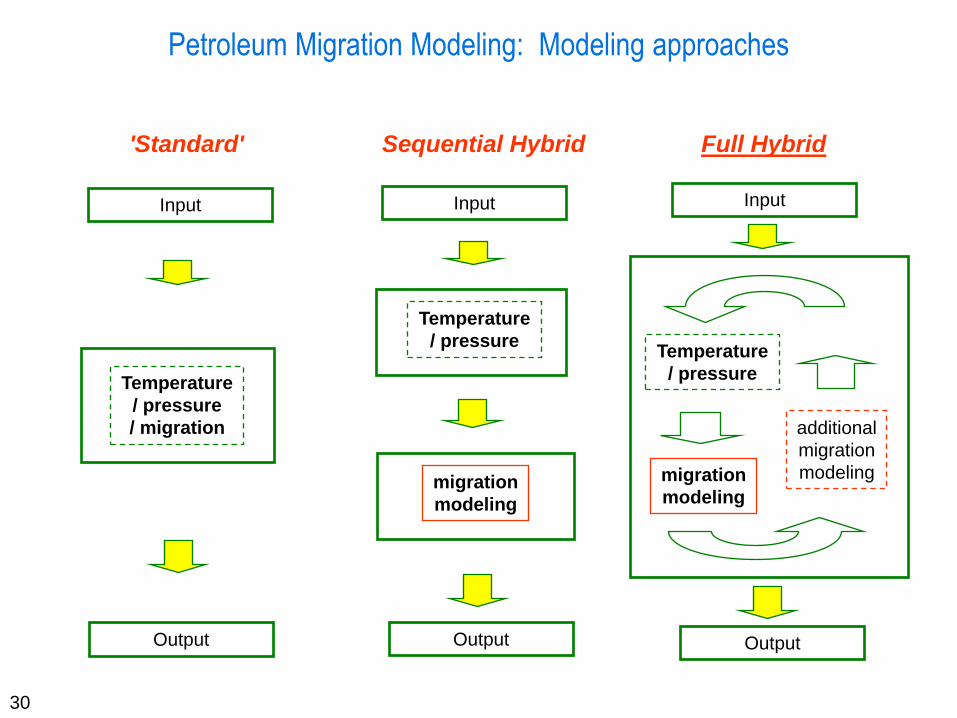
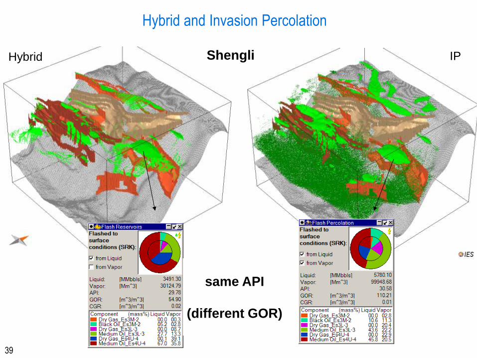
and Hybrid Modeling;
all multi-component
Fluid Properties
Flash Iterations
Geomechanics Rock Stresses
Seal Failure and
Fault Properties
4
From: TISSOT & WELTE (1984)
Petroleum Migration Definitions
5
Key factors of HC migration
Why do hydrocarbons migrate??
Hydrocarbons are lighter than water buoyancy
Hydrocarbons migrate as a separate phase from the
higher potential to a lower potential on the direct
way topography driven
How do hydrocarbons migrate??
6
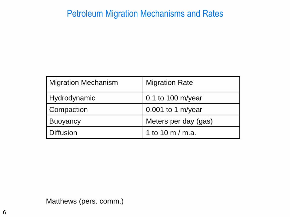
Petroleum Migration Mechanisms and Rates
Migration Mechanism Migration Rate
Hydrodynamic 0.1 to 100 m/year
Compaction 0.001 to 1 m/year
Buoyancy Meters per day (gas)
Diffusion 1 to 10 m / m.a.
Matthews (pers. comm.)
7
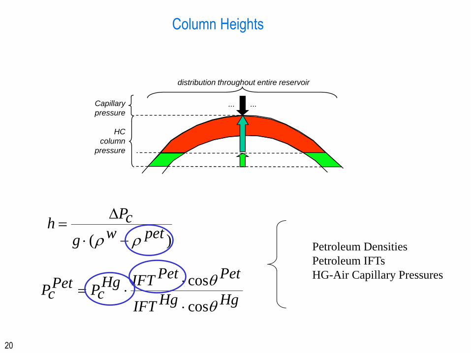
Properties and Processes: Capillary Pressures
The effect of interfacial tension is to create a finite pressure difference
between immiscible fluids called the capillary pressure:
Pc = Pnw - Pw
with Pw = wetting phase and Pnw non-wetting phase
Capillary pressure depends on the properties of the fluids and solid
surfaces, swa and cosqwa, and the tube radius, r.
When adhesion > cohesion, adhesive forces draw the fluid up the tube
until they are balanced by the weight of the fluid column.
When cohesion > adhesion, cohesive forces drag fluid down the tube
until they are balanced by the weight of the head difference forcing fluid
upwards.
8
Properties and Processes: Capillary Pressures
9
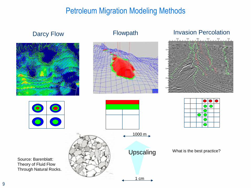
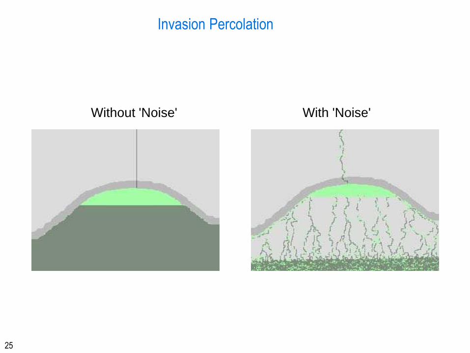
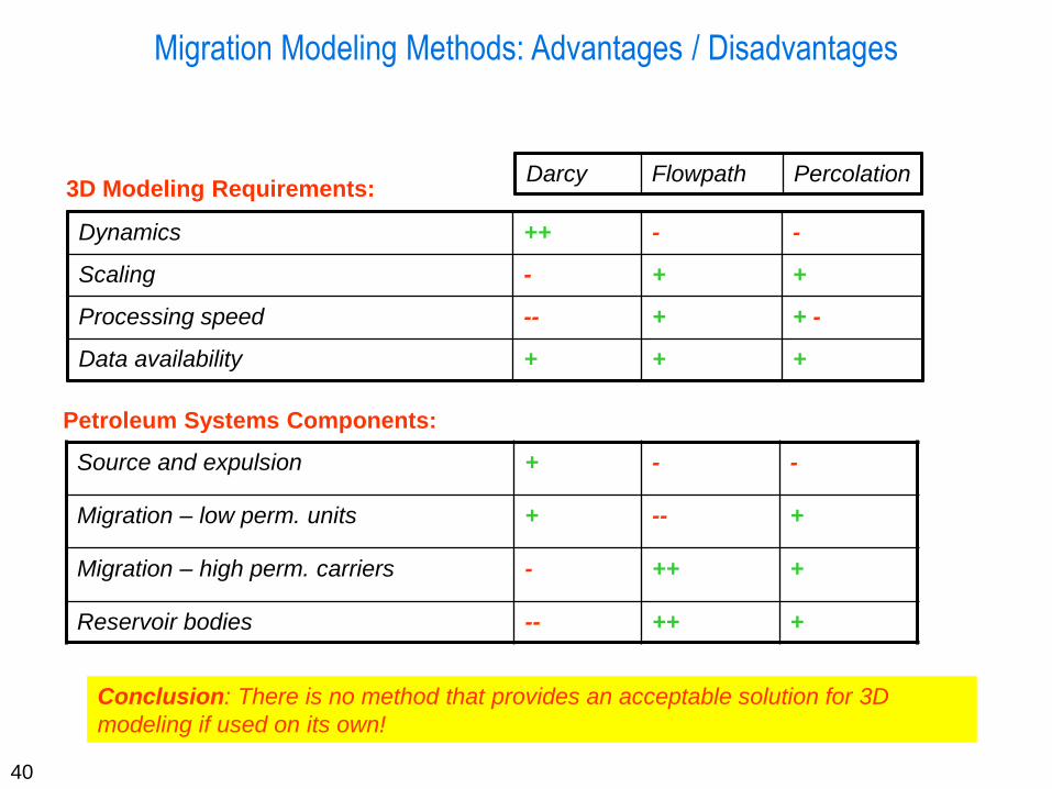
Petroleum Migration Modeling Methods
Darcy Flow Flowpath Invasion Percolation
Source: Barenblatt:
Theory of Fluid Flow
Through Natural Rocks.
1000 m
1 cm
Upscaling What is the best practice?
10
Darcy
Petroleum Migration Modeling Methods
11
Leakage
re-migration
Image courtesy BG International
Three Phase Flow through Porous Media and Multicomponents
Darcy Flow
12
Fluid Flow - Darcy Flow
The flow of vapour or liquids can be quantified using Darcy’s Law.
gradpk
dx
dpk
A
JQ
Q = Darcy velocity [m/s], [m2/m2/s]
J = volumetric flow [m3/s]
A = Area [m]
= dynamic viscosity [Pa*s]
dp/dx= gradient [Pa/m]
The constant of proportionality (k, permeability) obtained by Henri
Darcy depends on the properties of both the fluid (in Darcy’s
experiments, water) and the porous medium (in Darcy’s
experiments, sand and gravel).
13
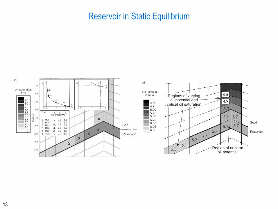
Reservoir in Static Equilibrium
0 S Swc co 1p
in t
Sw
pc
0 S Swc co 1Sw
12
3
45
Cell
1 Res. 1 0.1 6.1
2 Res. 1 0.1 5.7
3 Res. 55 0.5 5.74 Res. 95 0.9 5.7
5 Res. 96 1.3 5.7
6 Seal 1 1.7 5.7
S p uo c o
[%] [Mpa] [MPa]
Seal
Reservoir
2
3
4
5
6
6
pc
pin t
pce
pce
9080706050
40302010 0
Oil Saturationin %
a)
5.7
5.75.7
5.7 5.7
5.7 5.7
5.3
6.16.5
4.5
4.9
Regions of varyingoil potential and
critical oil saturation
Region of uniformoil potential
4.504.755.005.255.50
5.756.006.256.50
Oil Potentialin MPa
b)
Seal
Reservoir
14
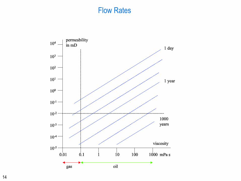
Flow Rates
15
Darcy Flow Modeling: Pros and Cons
Concept: Based on equations of flow through porous media
Advantages:
• Good general definition of carrier and seal system
• Easy inclusion of complex migration and transport processes such as multi-phase migration,
gas diffusion and PVT controls
• Only method that fully integrates pressures into the modeling process
Disadvantages:
• Long processing times, especially with large 3D data models
• For acceptable processing times, models must be simplified with resulting loss of information