32
Privileged and Confidential Information of DEI, Copyright 2012 Bat Deterrent Device PREPARED FOR

Privileged and Confidential Information of DEI, Copyright 2012
Bat Deterrent Device
PREPARED FOR
Privileged and Confidential Information of DEI, Copyright 2012
Objective
• To deter bats from approaching wind turbines using broadcast ultrasound in an effort to reduce bat fatalities at wind farms

Privileged and Confidential Information of DEI, Copyright 2012
Performance Targets
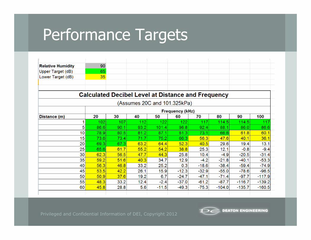
• 122 dB SPL at 1m distance (50 kHz)
• Effective range of 25m at 50% RH
• Effective range of 40m at 10% RH
• Frequency range of 20 kHz – 100 kHz
Privileged and Confidential Information of DEI, Copyright 2012
Performance Targets
Privileged and Confidential Information of DEI, Copyright 2012
Initial Design
• SensComp Series 600 Environmental Grade Electrostatic Transducer § Intended for operation in air at ultrasonic frequencies
§ Resonant frequency of 50 kHz, with a defined typical transmit response over 20 kHz – 100 kHz range
§ Better suited for harsh/outdoor environments
• 16 transducers (4x4 matrix) mounted on each device to achieve desired SPL § 110 dB with 1 transducer (per data sheet)
§ 122 dB with 16 transducers (per calculations)
• Transducers driven with 300V pulses at pseudo-random frequencies across 10 kHz – 100 kHz range

Privileged and Confidential Information of DEI, Copyright 2012
Initial Design
• Devices intended to be weather-resistant, but no environmental testing performed
• LED on each device to show supply power is present
• Timers used to power devices on for 14 hours each night
• 8 devices per wind turbine § 3 on each side of nacelle, pointing down
§ 1 on each end of nacelle, with reflectors to direct ultrasound up
• 300 VDC power supply § 120 VAC input power
§ 4 discrete channels per supply
§ 1 supply powered 4 devices
§ Installed inside nacelle with cables routed to each device

Privileged and Confidential Information of DEI, Copyright 2012
Initial Design
• $7740 (materials) per wind turbine § $340 per power supply (2x)
§ $570 per device (8x)
§ $2500 per mounting, cabling, etc. (1x)

Initial Design
Privileged and Confidential Information of DEI, Copyright 2012

Initial Design
Privileged and Confidential Information of DEI, Copyright 2012

Initial Design
Privileged and Confidential Information of DEI, Copyright 2012
Privileged and Confidential Information of DEI, Copyright 2012
Field Test - 2009
• 80 devices deployed in summer of 2009
• Installed on 10 turbines at Locust Ridge Wind Farm in PA

Privileged and Confidential Information of DEI, Copyright 2012
Field Test Results
• Water caused component damage in nearly all devices within first 6 weeks of installation § Indicated by LEDs that turned off
• All devices and most power supplies required rework/replacement before or during the field test § Transducers, transistors, and control boards replaced as needed
§ Additional sealant added to all seals
§ Vent added to allow operation with improved seal
• Significant downtime for many of the devices, resulting in poor coverage during portions of the field test

Failure Analysis
• Devices were not properly sealed § Water was able to enter the devices around the heat
sink and cause damage to the internal electronics
• Circuits did not have sufficient protection § Water damage resulted in permanent damage to the
electronics
§ Water damage resulted in shut down of the entire device
Privileged and Confidential Information of DEI, Copyright 2012
Design Changes - Sealing
• Designed & installed a custom gasket between the heat sink and the enclosure
• Gasket provided a better seal than the silicone used in the previous design
Privileged and Confidential Information of DEI, Copyright 2012

• Custom gasket inserted between heat sink and enclosure • 4 extra holes drilled in enclosure & heat sink to provide more
uniform compression around gasket • Thread-sealing Loc-Tite or rubber washers used on all screws
Design Changes - Sealing
Privileged and Confidential Information of DEI, Copyright 2012

Design Changes - Sealing
• Pressure leak (pressurized to 0.5 psi, bubble-tested for leaks) § No leaks detected on 3 different gasket installations
• Full submersion (submerged to 17” depth for 12-48 hours) § No water entry detected on any enclosure
• Simulated “rain” (subjected to “rain” per UL standard test method) § No water entry detected on any enclosure (1 hour min.)
Privileged and Confidential Information of DEI, Copyright 2012

Design Changes – Circuit Protection
• Added thermistors to protect each pair of transducers • Added thermistors to protect each output channel of the
power supplies • Components allow for recovery of circuitry once the fault
condition is removed (open when hot, close when cool) • Components in device only shut down 2 transducers at a
time so the entire device is not rendered nonoperational
Privileged and Confidential Information of DEI, Copyright 2012

• No impact in normal operating conditions • Little to no impact when rear of transducers
sprayed with water • Current limited (i.e., transducers off) when 1 or
both transducers submerged in water • Current limited (i.e., transducers off) when rear of
transducer flooded with water
Privileged and Confidential Information of DEI, Copyright 2012
Design Changes – Circuit Protection

• Performance returned to normal after fault was removed (i.e., transducers were dried off)
• No PCB components were damaged • No fuses were blown
§ Only exception was a cold start with all 16 transducers flooded with water
§ Still no damaged components
Privileged and Confidential Information of DEI, Copyright 2012
Design Changes – Circuit Protection
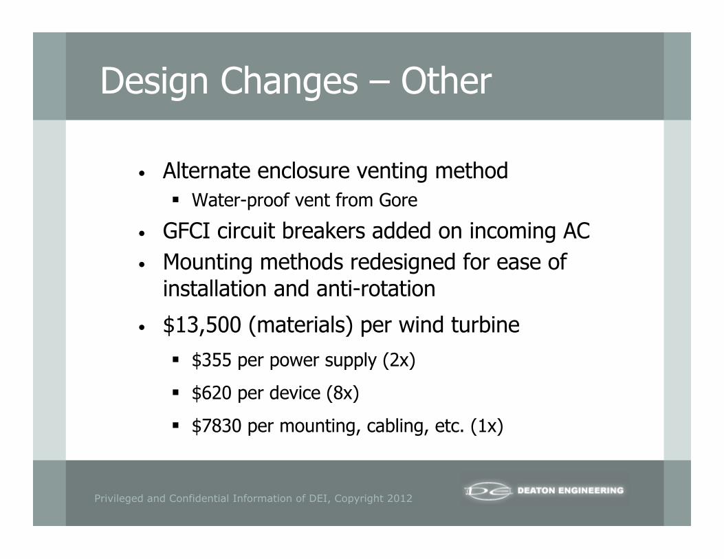
Design Changes – Other
• Alternate enclosure venting method § Water-proof vent from Gore
• GFCI circuit breakers added on incoming AC • Mounting methods redesigned for ease of
installation and anti-rotation
• $13,500 (materials) per wind turbine
§ $355 per power supply (2x)
§ $620 per device (8x)
§ $7830 per mounting, cabling, etc. (1x)
Privileged and Confidential Information of DEI, Copyright 2012
Privileged and Confidential Information of DEI, Copyright 2012
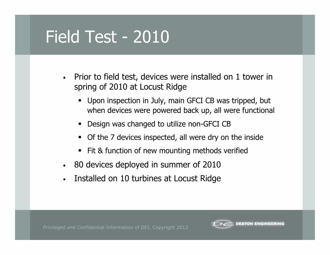
Field Test - 2010
• Prior to field test, devices were installed on 1 tower in spring of 2010 at Locust Ridge
§ Upon inspection in July, main GFCI CB was tripped, but when devices were powered back up, all were functional
§ Design was changed to utilize non-GFCI CB
§ Of the 7 devices inspected, all were dry on the inside
§ Fit & function of new mounting methods verified
• 80 devices deployed in summer of 2010
• Installed on 10 turbines at Locust Ridge

Privileged and Confidential Information of DEI, Copyright 2012
Field Test Results
• Anti-rotation clamps performed well § 1 tower retained the old mounting method; the mounting arms
rotated on this tower, but not on the others
• 5 welded joints on the mounting arms were broken § Some were completely broken prior to removal, others were
damaged and then broke completely during the removal process
§ It was observed that the mounting arms experienced a great deal of bending and twisting, which likely led to the failure
§ These same mounting arms withstood the previous field test in 2009

Privileged and Confidential Information of DEI, Copyright 2012
Field Test Results
• Devices still allowed water to enter, but they were much more resistant than previous efforts § Water was detected in 27 of the 80 devices
§ Water was not detected in any of the devices that were mounted farthest from the turbine blades
§ Water was not detected in any of the devices with the reflector
• Fuses were blown in 27 of the 80 devices, but it is unclear whether the fuses blew before, during, or after the field test
Privileged and Confidential Information of DEI, Copyright 2012
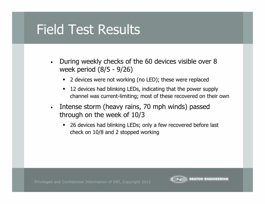
Field Test Results
• During weekly checks of the 60 devices visible over 8 week period (8/5 - 9/26) § 2 devices were not working (no LED); these were replaced
§ 12 devices had blinking LEDs, indicating that the power supply channel was current-limiting; most of these recovered on their own
• Intense storm (heavy rains, 70 mph winds) passed through on the week of 10/3 § 26 devices had blinking LEDs; only a few recovered before last
check on 10/8 and 2 stopped working

Privileged and Confidential Information of DEI, Copyright 2012
Field Test Results
• Most of the power supplies did not have any damage § 62 were still regulating at approx. 300 VDC
§ 16 were supplying unregulated voltage (approx. 370 VDC)
§ 2 were supplying low voltages (approx. 185 VDC)
• Devices with a high voltage supply will continue to operate, but with more downtime as temperatures will be higher inside the device
• Devices with a low voltage supply will continue to operate, but they will be less effective
Privileged and Confidential Information of DEI, Copyright 2012
Field Test Results
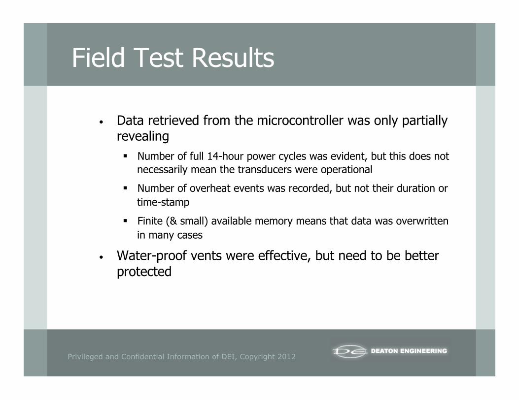
• Data retrieved from the microcontroller was only partially revealing § Number of full 14-hour power cycles was evident, but this does not
necessarily mean the transducers were operational
§ Number of overheat events was recorded, but not their duration or time-stamp
§ Finite (& small) available memory means that data was overwritten in many cases
• Water-proof vents were effective, but need to be better protected

Privileged and Confidential Information of DEI, Copyright 2012
Field Test Results
• Overall, much better performance & coverage than previous field test
• Devices were able to recover from many failure modes
• Design still needs additional ruggedization to reduce downtime & increase coverage

Privileged and Confidential Information of DEI, Copyright 2012
Proposed Design Changes
• Improve the environmental rating of the devices • Protect water-proof vents from physical damage • Improve the strength of the mounting arm welded joints • Redesign mounting arms to withstand the fatigue loading of the
wind
Privileged and Confidential Information of DEI, Copyright 2012
Proposed Design Changes
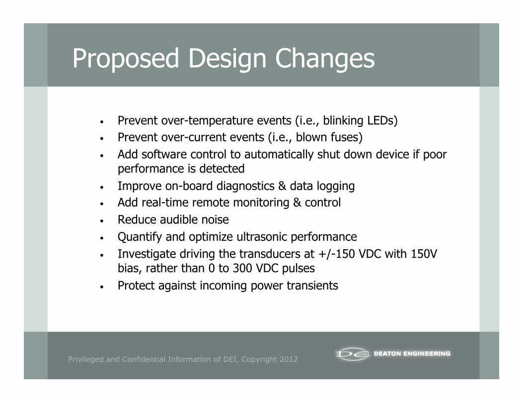
• Prevent over-temperature events (i.e., blinking LEDs) • Prevent over-current events (i.e., blown fuses) • Add software control to automatically shut down device if poor
performance is detected • Improve on-board diagnostics & data logging • Add real-time remote monitoring & control • Reduce audible noise • Quantify and optimize ultrasonic performance • Investigate driving the transducers at +/-150 VDC with 150V
bias, rather than 0 to 300 VDC pulses • Protect against incoming power transients

Privileged and Confidential Information of DEI, Copyright 2012
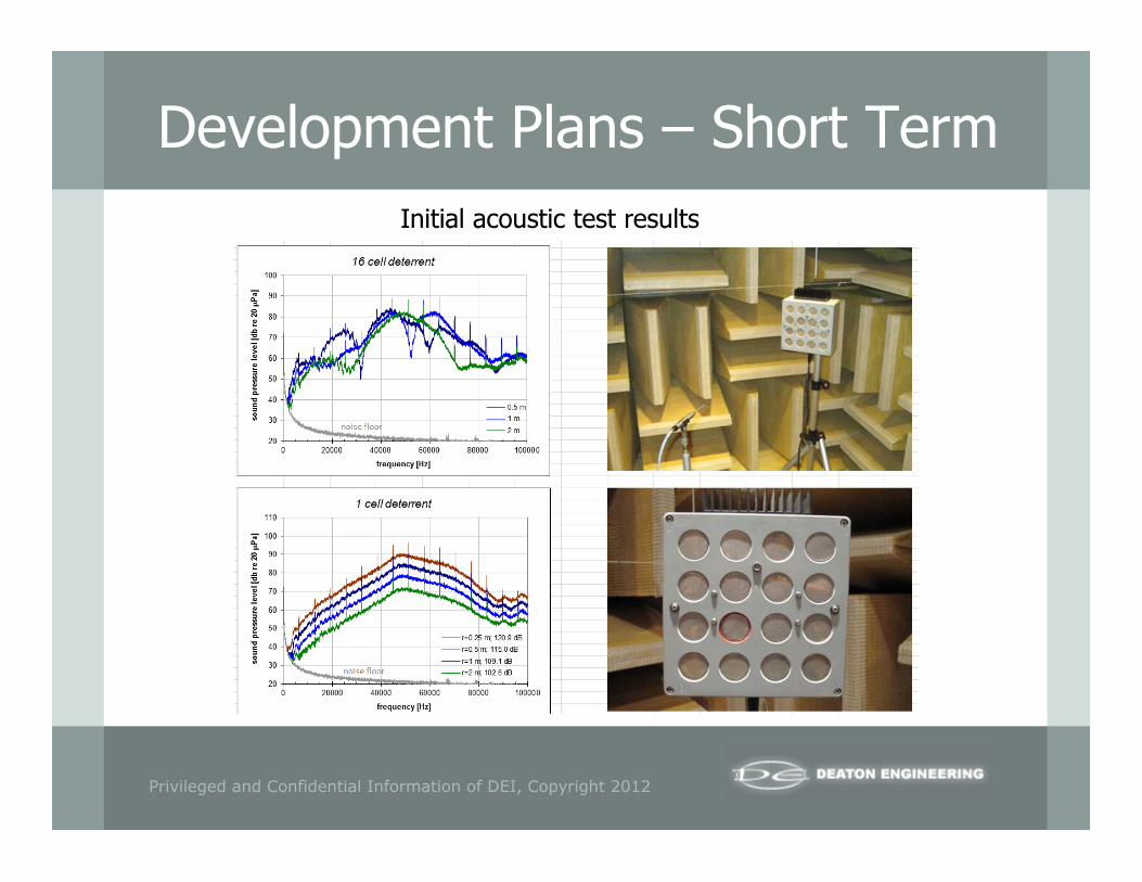
Development Plans – Short Term
• Acoustic lab testing (in progress) § 0–100 kHz spectrum at 1m on devices w/1 & 16 transducers
§ Spherical dispersion tests on devices with spectra measured at 0.5m, 1m, 2m etc.
§ Directivity tests, if possible
• Research & development ($30k)
§ Proposed design changes
§ Reassessment of selected transducer
§ Analysis of quantity/location of devices per wind turbine
• Definition of new design requirements ($10k)
Privileged and Confidential Information of DEI, Copyright 2012
Development Plans – Short Term Initial acoustic test results

Privileged and Confidential Information of DEI, Copyright 2012
Development Plans – Long Term
• Deployment of 600 devices (20 devices on 30 wind turbines) ($1.229m)
• Labor Estimate ($471.5k) § Design (6 months, $220k)
§ Assembly & Test ($187.5k)
§ Installation/Removal & Field Test Support ($64k)
• Materials Estimate ($757.5k) § Devices ($600k)
§ Power Supplies ($97.5k)
§ Mounting Hardware ($60k)


