BATCHCONTROL 5014 C Compact Electromagnetic Flowmeters with CANopen bus interface
Please note! Do not open the housing of the BATCHCONTROL 5014C. Danger of contamination with substances likely to destroy the moisture barrier of the electronic equipment (e.g. if CIP or SIP cleaned from the outside). Therefore, please contact your KROHNE Service engineer before you open the housing.
Installation and operating instructions 2 BATCHCONTROL
Contents System description 4 Standards and approvals 4 Product liability and warranty 4 Functional description BATCHCONTROL IFM 5014C 5 Part A System installation and start-up 6 - 15 1 Installation in the pipeline 6 - 12 1.1 Important information 6 1.2 Suggestions for installation 7 1.3 Installation requirements 8 1.3.1 Position of flange 9 1.3.2 Example: centering and sealing the primary head 9 1.3.3 Grounding 9 1.4 Installation of the primary head 10 1.4.1 Device description 10 1.4.2 Installation of the IFM 5014C 10 1.5 Size of connections 11 - 12 1.5.1 Fastening with tie bolts 11 1.5.2 Fastening with bolts (option) 12 2 Electrical connection 13 - 14 2.1 Important information 13 2.2 Attachment plugs 13 2.3 Power supply and CAN bus 14 2.4 Input and output 14 2.5 Block circuit diagram 14 3 Start-up 15 3.1 Checking for availability 15 3.2 Factory settings 15 Part B IFC 014 batch controller 16 - 20 4 Description of functions 16 - 20 4.1 Contact outputs 16 4.2 Voltage input 16 4.3 Contact input 16 4.4 CAN bus and parameter 16 - 17 4.5 Temperature sensors 17 4.6 Flow sensor 17 4.7 An example for a filling process 17 - 20 Part C Service 21 5 Illustrations of printed circuit boards 21 Part D Technical Data, block diagram and measuring principle 22 - 28 6 Technical data 22 - 26 6.1 Flow during filling and fill volume 22 6.2 Flowmeters 22 6.3 Signal converter 23 6.4 Error limits at reference conditions 24 6.5 Dimensions and weights 25 - 26 6.6 Instrument nameplates 26 7 Block diagram 27
Installation and operating instructions 3BATCHCONTROL
8 Measuring principle 28 Part E Annex 29 - 47 E1 Index 29 E2 CAN parameter 30 - 45 E3 Form to accompany returned device 46 Please note! Do not open the housing of the BATCHCONTROL IFM 5014C. Danger of contamination with substances likely to destroy the moisture barrier of the electronic equipment (e.g. if CIP or SIP cleaned from the outside). Therefore, please contact your KROHNE Service engineer before you open the housing.
Installation and operating instructions 4 BATCHCONTROL
System description The BATCHCONTROL IFM 5014C compact electromagnetic flowmeter is a precision instrument designed for the linear flow measurement of liquid products and controlling the filling process. The products need to be electrically conductive: > 5 µS/cm (except for water) > 20 µS/cm (for water) The full-scale range Q100% can be set as a function of the meter size: DN 2.5 – 40 and 1/10” – 11/2” Q100% = 0.0015 - 15 l/s This is equivalent to a flow velocity of 0.2 - 12 m/s. Standards and approvals
• BATCHCONTROL IFM 5014C with the IFC014 signal converter meets the EU-EMC Directives and bears the CE and 3A symbol.
• The 3A approval covers only the meter without adapter.
• All factories and production sequences are ISO 9001 certified.
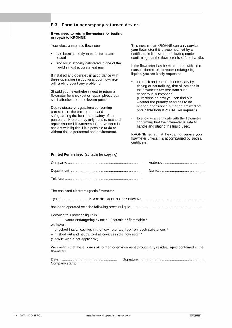
Product liability and warranty The compact BATCHCONTROL IFM 5014C electromagnetic flowmeter is designed exclusively for measuring the volumetric flowrate of electrically conductive, liquid process products. The compact flowmeter is not suitable for use in hazardous areas. Other flowmeter series are available for such applications. Responsibility as to suitability and intended use of this compact electromagnetic flowmeter rests solely with the operator. Improper installation and operation of the flowmeters (systems) may lead to loss of warranty. In addition, the “General conditions of sale“ forming the basis of the purchase contract are applicable. If BATCHCONTROL 5014C flowmeters need to be returned to KROHNE, please note the infor-mation given on the last-but-one page of these instructions. KROHNE regret that they cannot repair or check your flowmeter(s) unless these are accompanied by the completed form sheet.
Installation and operating instructions 5BATCHCONTROL
Functional description BATCHCONTROL IFM 5014C The volume to be filled into the container is measured “in line“ by means of the electromagnetic flowmetering system. The BATCHCONTROL closes the filling valve once the preset filling volume has been reached. It is always the preset target volume that is filled into the container. The signal converter converts the measured flowrate signal into volume that are transfered to the integrated batch controller. The influence of valve closing times and other dynamic factors can be corrected by the adaptive correction formalism of the BATCHCONTROL 5014C. The use of state-of-the-art microprocessor electronics and the high-speed analog/digital converter also enables changes in the flowrate to be sensed precisely. This technology ensures high reproducibility and long-term stability.
Installation and operating instructions 6 BATCHCONTROL
Part A System installation and start-up
1 Installation in the pipeline 1.1 Important information The following recommendations should be observed to ensure proper functioning of the flowmeter – PLEASE NOTE.
• Measuring tube must be filled completely at all times.
• Direction of flow: the blue arrow on the housing of the primary head must point in the direction of flow. If for structural reasons the flowmeter can only be installed invers to the direction of flow, the direction of flow measurement can be reprogram-med.
• Stud bolts and nuts: to fit, make sure there is sufficient room next to the pipe flanges.
• Vibration: support the pipeline on both sides of the flowmeter. Vibration level to IEC 068-2-34: below 2,2g in the 20 - 2000 Hz frequency range.
• Radiant heat: avoid e.g. from hot product tanks, insulate if necessary.
• Avoid strong electromagnetic fields in vicinity of flowmeter.
• Straight Inlet run ≥ 5 x DN and straight outlet run ≥ 2 x DN, measured from the electrode axis (DN = meter size).
• Vortex or corkscrew flow: increase length of inlet and outlet runs or install flow straighteners.
• Mixing different process liquids: install flowmeter upstream of mixing point or at an adequate distance downstream, minimum of 30 x DN (DN = meter size), otherwise display may be unsteady.
• Plastic pipes and internally coated metal pipes: grounding rings required, see “Grounding“, Section 1.3.3.
• Heat-insulated pipelines: do not insulate flowmeter.
• Zero setting: not required. For checking purpose, it should be possible to set “zero“ flow velocity in the completely filled measuring tube. Shutoff valves should therefore be provided either downstream or upstream and downstream of the flowmeter.
• Ambient temperature -25°C to +60°C
• Process temperature max. 140 °C
• Transport and storage temperature -25°C to +60°C
Limits imposed by the material used for the measuring tube for process temperature, thermal shock limit, pressure and vacuum, see Section D page 22. Please note! The ceramic measuring tube must not contact metal parts (flange, pipeline). This can destroy the flowmeter!
1
Installation and operating instructions 7BATCHCONTROL
1.2 Suggestions for installation
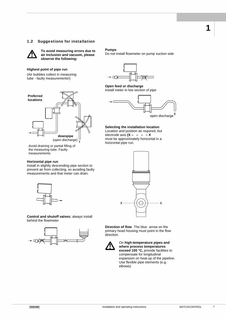
To avoid measuring errors due to air inclusion and vacuum, please observe the following:
Highest point of pipe run (Air bubbles collect in measuring tube - faulty measurements!)
Horizontal pipe run Install in slightly descending pipe section to prevent air from collecting, so avoiding faulty measurements and that meter can drain.
Control and shutoff valves: always install behind the flowmeter
Pumps Do not install flowmeter on pump suction side
Open feed or discharge Install meter in low section of pipe
open discharge
Selecting the installation location Location and position as required, but electrode axis (X – – – – X must be approximately horizontal in a horizontal pipe run.
Direction of flow The blue arrow on the primary head housing must point in the flow direction.
On high-temperature pipes and where process temperatures exceed 100 °C, provide facilities to compensate for longitudinal expansion on heat-up of the pipeline. Use flexible pipe elements (e.g. elbows).
Preferredlocations
downpipe(open discharge)
Avoid draining or partial filling ofthe measuring tube. Faultymeasurements.
x x
1
Installation and operating instructions 8 BATCHCONTROL
flowmeter in the version as ordered • Installation and operating instructions,
as agreed • Certificate of system calibration data
(as agreed) Excluding fitting accessories. Stud bolts, gaskets, etc., to be provided by customer. All operating data and function values are factory set according to your order specifications.
Requirements Use in the food industry The IFM 5014C is specifically suitable for use in the food and beverage industry or similar sterile processes. The IFM 5014C is steam-resistant. The measuring tube can be SIP or CIP cleaned when in installed condition. During the cleaning the meter(s) must be switched off to maintain the reliability of the unit(s).
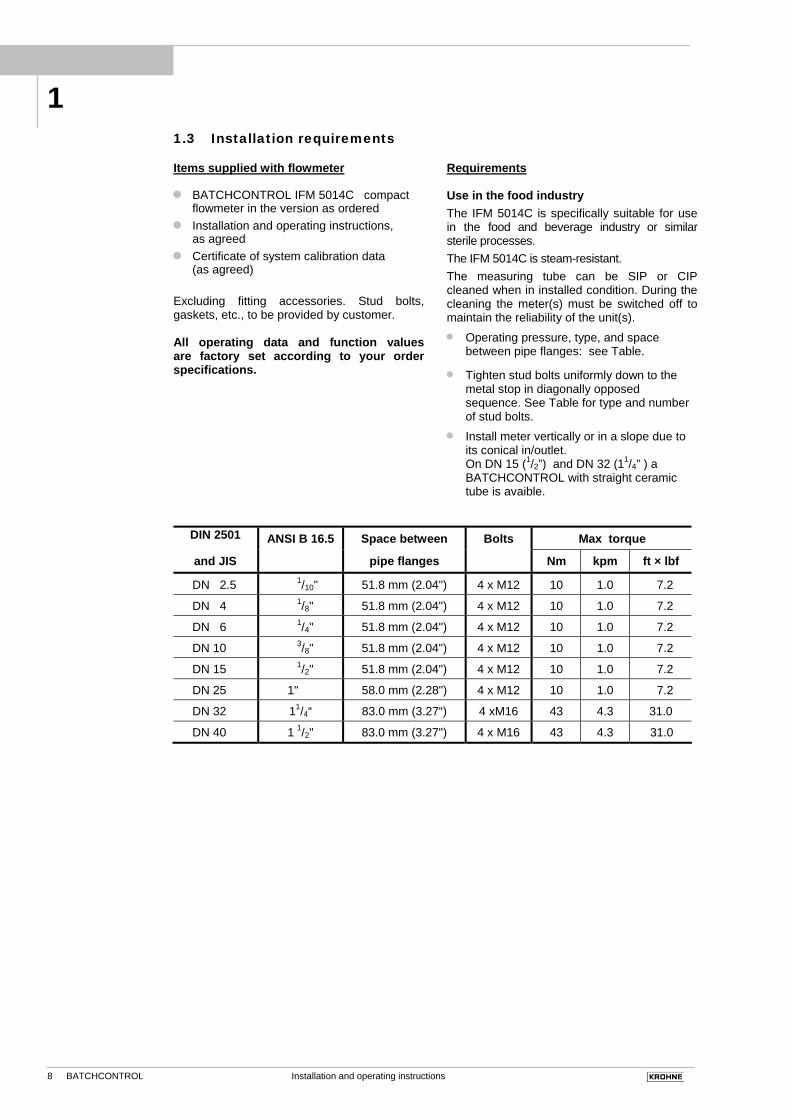
• Operating pressure, type, and space between pipe flanges: see Table.
• Tighten stud bolts uniformly down to the metal stop in diagonally opposed sequence. See Table for type and number of stud bolts.
• Install meter vertically or in a slope due to its conical in/outlet. On DN 15 (1/2”) and DN 32 (11/4” ) a BATCHCONTROL with straight ceramic tube is avaible.
DIN 2501 ANSI B 16.5 Space between Bolts Max torque
and JIS pipe flanges Nm kpm ft × lbf
DN 2.5 1/10" 51.8 mm (2.04") 4 x M12 10 1.0 7.2
DN 4 1/8" 51.8 mm (2.04") 4 x M12 10 1.0 7.2
DN 6 1/4" 51.8 mm (2.04") 4 x M12 10 1.0 7.2
DN 10 3/8" 51.8 mm (2.04") 4 x M12 10 1.0 7.2
DN 15 1/2" 51.8 mm (2.04") 4 x M12 10 1.0 7.2
DN 25 1" 58.0 mm (2.28") 4 x M12 10 1.0 7.2
DN 32 11/4“ 83.0 mm (3.27“) 4 xM16 43 4.3 31.0
DN 40 1 1/2" 83.0 mm (3.27") 4 x M16 43 4.3 31.0
1
Installation and operating instructions 9BATCHCONTROL
1.3.1 Position of flanges Install flowmeter in line with the pipe axis. Pipe flange faces must be parallel to each other, max. allowable deviation: Lmax – Lmin ≤ 0.5 mm ≤ 0.02"
1.3.2 Example: centering and sealing
the primary head The primary head is centered between the pipe flanges with the aid of the precise geometric fitting (guide collar on primary head). Detail drawings see Sect. 1.5.
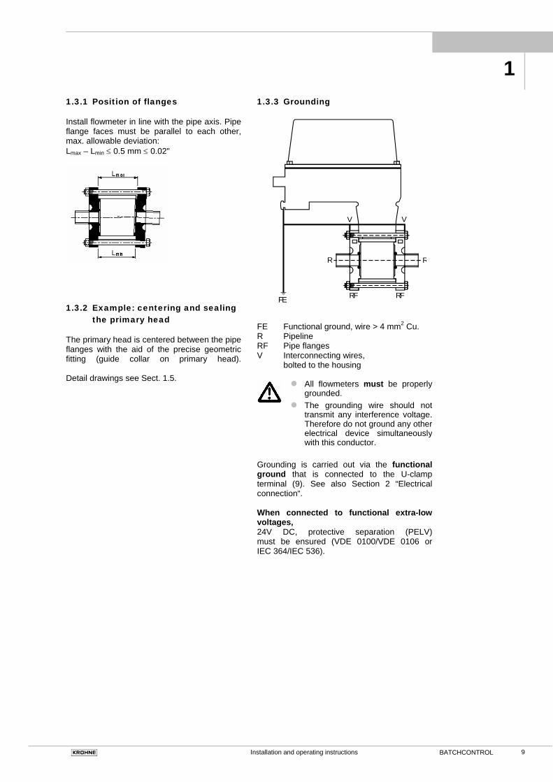
1.3.3 Grounding
FE Functional ground, wire > 4 mm2 Cu. R Pipeline RF Pipe flanges V Interconnecting wires, bolted to the housing
• All flowmeters must be properly grounded.
• The grounding wire should not transmit any interference voltage. Therefore do not ground any other electrical device simultaneously with this conductor.
Grounding is carried out via the functional ground that is connected to the U-clamp terminal (9). See also Section 2 “Electrical connection“. When connected to functional extra-low voltages, 24V DC, protective separation (PELV) must be ensured (VDE 0100/VDE 0106 or IEC 364/IEC 536).
FE
V V
R R
RF RF
1
Installation and operating instructions 10 BATCHCONTROL
1.4 Installation of the primary head 1.4.1 Device description
• BATCHCONTROL IFM 5014C 4 Cover, signal converter 5 Primary head 7 Connector for the six in-/outputs 8 Connector for power and CAN Bus 9 U-clamp terminal for functional ground 10 Fastening screws for cover 11 Locating collar, primary head
• Accessories from system manufacturer
12 O-ring gasket 13 Special pipe flange 14 Stud bolt with lock washer, plain washer and nut
To facilitate servicing of the primary head, please note the following points:
• It must be possible to shut off the flow
through the pipeline upsteam of the primary head (provide shutoff valve),
• Drain the pipe system before removing the primary head (provide drain valve),
• Support the pipeline on both sides of the flowmeter when located in a long, freely suspended section to facilitate removal of the primary head.
1.4.2 Installation of the IFM 5014C • Position gaskets (12) in the pipe flanges.
• Type and location of gaskets as specified by the manufacturer of the filling machine (see Sect. 1.3.2 “Centering of the primary head”).
• Insert primary head (5) between the pipe flanges (13) in line with the pipe axis.
• For spacing and location of the pipe flanges, see Sect. 1.3 “Position of flanges”.
• Press pipe flanges against flowmeter.
Centering ring of pipe flanges must snap into place in the guide collar (11) of the primary head.
• Insert stud bolts (14) with washers into the
holes in the pipe flanges. Fit nuts to stud bolts with lock washer.
• Tighten stud bolts and nuts down to the metal stop symmetrically. Check all bolts after starting up the pipe system, and retighten when any leaks show.
• Connect ground conductor to U-clamp terminal (9).
• Connect power supply, CAN bus and outputs to connector plugs (7, 8) on signal converter housing (4).
See Section 2.2 and 2.3 for details of electrical connection.
1
Installation and operating instructions 11BATCHCONTROL
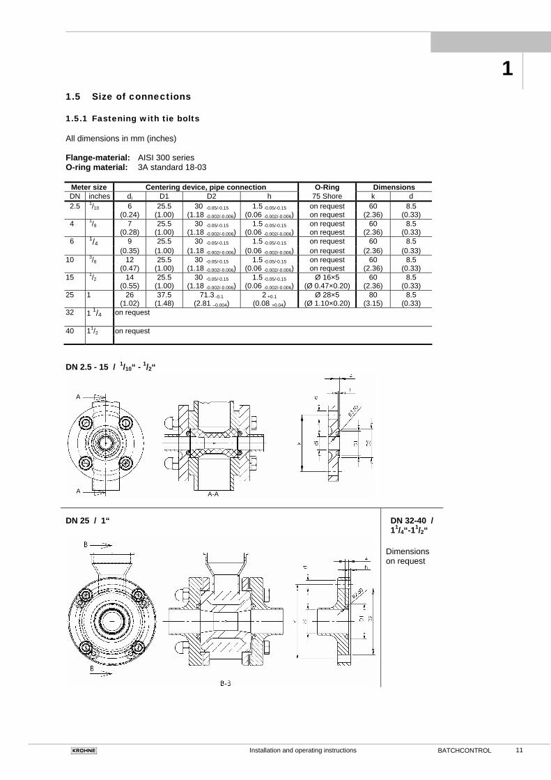
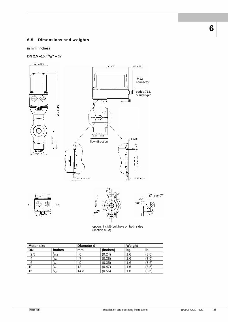
1.5 Size of connections 1.5.1 Fastening with tie bolts All dimensions in mm (inches) Flange-material: AISI 300 series O-ring material: 3A standard 18-03
Meter size Centering device, pipe connection O-Ring Dimensions DN inches di D1 D2 h 75 Shore k d
Installation and operating instructions 12 BATCHCONTROL
1.5.2 Fastening with bolts (option) All dimensions in mm (inches) * Flange-material : AISI 300 series O-ring material : 3A standard 18-03 Meter size Centering device, pipe connection O-ring Screw thread (option)
gaskets 2× M4 4× M6 DN inches di D1 D2 h 75 Shore k d k d
Installation and operating instructions 13BATCHCONTROL
2 Electrical connection
2.1 Important information
Be sure to take note of the following information in order to ensure proper functioning of the signal converter.
Please note: 1) Overvoltage class:
In conformity with VDE 0120, equivalent to IEC 664, the compact flowmeters are designed for overvoltage category III in the supply circuits and overvoltage category II in the output circuits.
2) Safety isolation: The compact flowmeters must be provided with an isolating facility.
Electrical connection and repairs may only be carried out by qualified personnel.
• Protect the flowmeter from direct radiant
heat (e.g. hot-product tanks), insulate if necessary.
• Do not expose flowmeter to intense vibration. If necessary, support the pipeline to the right and left of the flowmeter. Level of vibration in accordance with IEC 068-2-34: below 2.2g in the 20 - 2000 Hz frequency range.
• Note information given on the instrument nameplate, voltage.
• The FE functional ground for the supply power should for measurement reasons be connected to the separate U-clamp terminal on the signal converter housing.
• When connected to a functional extra-low voltage of 24 V DC, protective separation (PELV) must be ensured (VDE 0100 / VDE 0106 or IEC 364 / IEC 536 or equivalent national regulations)..
2.2 Attachment plugs
Manufacturer Series and type Description Binder Series 715 Moulded plug, straight or
angle-entry form Series 763 Integrally extruded plug
with cable in various lengths
Hirschmann E-Series ELKA 4012 and
ELWIKA 4012 Moulded plug, straight or angle-entry form
ELKA KV 4412 and ELWIKA KV 4412
Integrally extruded plug with cable in various lengths
Lumberg RK-Series RKC and RKCW Moulded plug, straight or
angle-entry form RKT and RKWG Integrally extruded plug
with cable in various lengths
Amphenol Series C 164 P Moulded plug, straight or angle-entry form
Series C 164 P compact
Integrally extruded plug with cable in various lengths
Coninvers Series BC Moulded plug, straight form, especially suitable for high-interference environments (keyword: EMC)
Pin-assignment and alignment of cable entry body
Installation and operating instructions 14 BATCHCONTROL
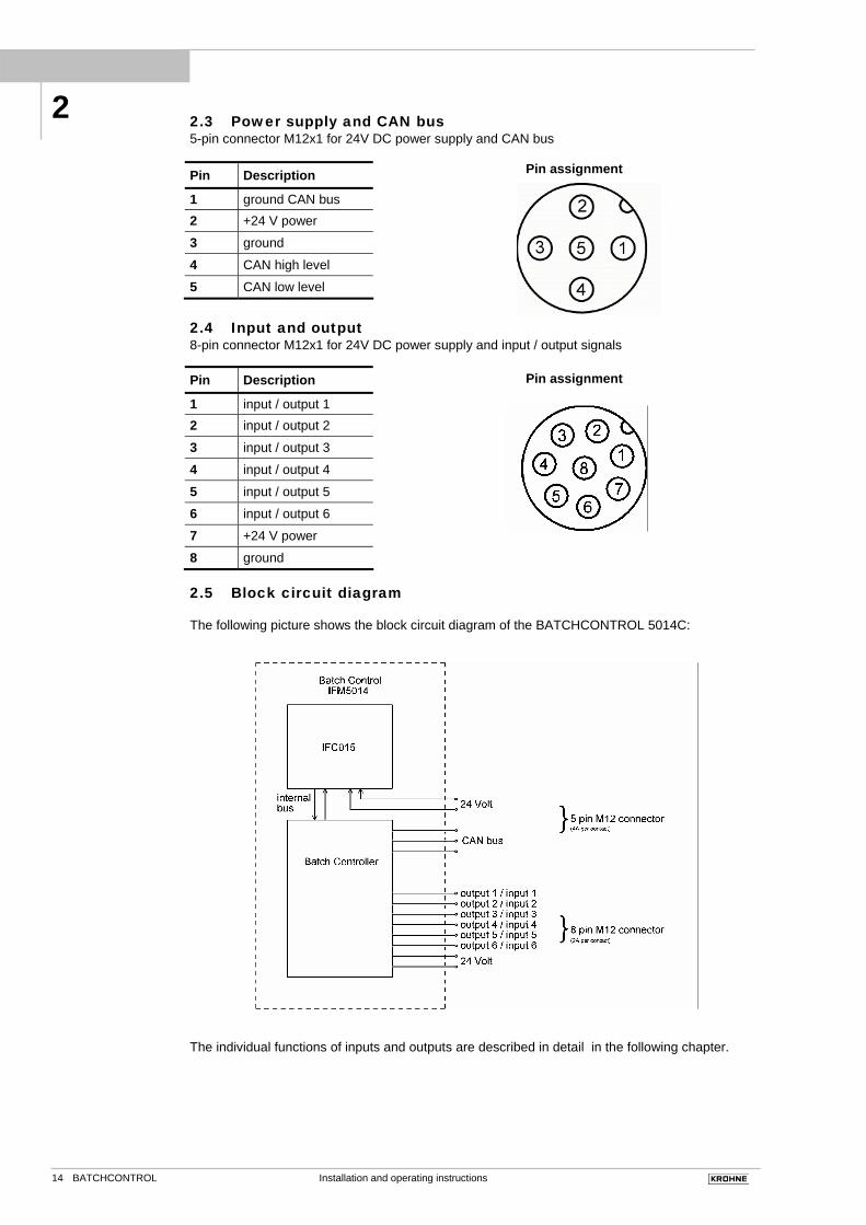
2.3 Power supply and CAN bus 5-pin connector M12x1 for 24V DC power supply and CAN bus
Pin assignment
2.4 Input and output 8-pin connector M12x1 for 24V DC power supply and input / output signals
Pin assignment
2.5 Block circuit diagram The following picture shows the block circuit diagram of the BATCHCONTROL 5014C:
The individual functions of inputs and outputs are described in detail in the following chapter.
Pin Description
1 ground CAN bus 2 +24 V power
3 ground
4 CAN high level
5 CAN low level
Pin Description
1 input / output 1 2 input / output 2
3 input / output 3
4 input / output 4
5 input / output 5
6 input / output 6
7 +24 V power
8 ground
2
Installation and operating instructions 15BATCHCONTROL
3 Start-up Before powering the system, check that it has been installed correctly according to Sections 1 and 2. The compact flowmeter is delivered ready for operational use. All operating data have been factory set in accordance with your specifications. Power the unit, and the flowmeter will start process flow measurement immediately. 3.1 Check for availability Please note! Do not open the housing of the BATCHCONTROL IFM 5014C. Danger of contamination with substances likely to destroy the moisture barrier of the electronic equipment (e.g. if CIP or SIP cleaned from the outside). Therefore, please contact your KROHNE Service engineer before you open the housing.
• The measurement status is signalled by the light-emitting diodes (LED) below the cover of the converter housing (see amplifier board on right).
LED 1 LED 2 Function
flashing off in order flashing flashing overdriving
on flashing Fatal Error (defective operating
parameter) off on defective hardware off off no supply voltage
or hardware is defective
All operating data can be set and stored by means of a personal computer via the CAN bus interface. The digital CAN bus interface allows the complete filling procedure to be graphically represented on the PC, thus providing visualization of system and valve properties. 3.2 Factory settings All operating data are factory-set according to your order specifications. The table of standard factory settings is shown at the end of the manual.
3
LED 1 LED 2
Installation and operating instructions 16 BATCHCONTROL
Part B IFC 014 batch controller 4 Description of functions Six contacts are available for the different functions. Every contact can be switched over as a switching output, switching input or analogous by software. In addition, the device has one CAN bus interface for communication, two internal temperature sensors and one flow sensor . 4.1 Contact outputs Up to six power outputs (24V / I < 200mA), switch over to ground (low side driver) or to the 24V supply voltage (high side driver), can be programmed by software. The drivers communicate via the internal data bus with the logic and the other control and monitoring functions: undervoltage, overvoltage, overtemperature and failure detection. When commutating inductive loads, the dissipated power peak is be significantly reduced by the internal freewheeling diode. All power drivers are connected to the supply voltage. These are monitored by overvoltage and undervoltage comparators with hysteresis, so that the correct function can be checked in the application at any time. They are short-circuit resistant (Imax 2A). Overcharge is indicated by the bus interface. Consumer are controlled for disconnections (cable break) by the outputs, indication by the Bus interface. All valve outputs are on equal basis. The following functions can be adjusted:
• Without use (off) • Permanently on (breakdown identification) • Binary output controlled by the bus • Switch on after time or after reaching target volume or after reaching a defined volume flow • Turn off after time or reaching target volume or after reaching a defined volume flow • Automatically, regulation for target filling volume • Customers specific programming
4.2 Voltage input Up to six voltage inputs with common ground for 24V supply voltage are available. The voltage range is from 0 volts up to 11 volts with a resolution of 8 bits. The input impedance of the inputs ‘1’ and ‘2’ is 220kOhm, for the inputs ‘3’ up to ‘6’ is 22kOhm. The update rate is 8ms. For every input scaling factors and offsets can be defined. To use this functionality the corresponding output has to be switched off. Each voltage input can be programmed for the following functions:
• Without use (off) • Voltage input for the bus • Start of filling process • Emergency off • Customers specific programming
4.3 Contact inputs Up to six inputs with common ground for 24V supply voltage. To use this functionality the corresponding output has to be switched off. Each control input can be programmed for the following functions:
• Without use (off) • Binary input for the bus • Starting of filling process • Emergency off • Customers specific programming
4.4 CAN bus and parameter For the interface the CAN bus is used. Baud rates within the range 20k up to 1M Baud are possible. For the protocol CANopen is applied. The interface has a galvanic connection to the 24V supply! The possible functions are described in one of the following chapter. Default Baud rate is 20k Baud.
4 4
Installation and operating instructions 17BATCHCONTROL
The object dictionary for the parameters is subdivided into the following groups:
Object number range Description 10xxH CAN open parameter 300xH Flow sensor parameter 301xH Electronic temperature sensor 302xH Liquid temperature sensor 303xH Function block 1 304xH Function block 2 305xH Function block 3 306xH Function block 4 307xH Function block 5 308xH Function block 6 309xH Batching 30AxH CAN parameter 32xxH Customer specific 1 bit memory 33xxH Customer specific 8 bit memory 34xxH Customer specific 16 bit memory 35xxH Customer specific 32 bit memory
The complete list of all parameters can be found at the end of the manual. To be able to represent the variety of all possible messages on the bus, the CANopen definition hasn't been used at the definition of the TPDOs and RPDOs. If this function is programmed, then the device sends at every message in the first data byte a description and in the following bytes the data. This shall be explained at an example:
The user needs every flow measurement for the analysis of the valve. With the parameter 3002.02 the PDO is defined. After this parameter was stored in the BATCHCONTROL 5014C, it sends the actual volume flow every 20 ms. The Telegramm starts in the first byte with the descriptor (in this case 01H) followed by the measurement value in float format. Many parameters can use the same PDO. The distinction of the data is made by the first byte (called descriptor in the parameter list at the end of the manual).
This function shouldn't be used in CANopen nets.
4.5 Temperature sensors Two temperature sensors are installed inside the BATCHCONTROL 5014C. The first one is mounted on the BATCHCONTROL print board. This one measures the electronic temperature. The information can be important during the CIP process or in hot filling application. If the temperature is higher then 70°C the life time of the electronic components are reduced. An upper and lower setpoint can be programmed. If one of this points are reached, an alarm message is send via the CAN bus. Alternativly this information can be programmed for an output, which is used as an alarm output. The second sensor is mounted on the outside of the ceramic pipe. It has the same functionality as the electronic temperature sensor. Since the temperature sensor doesn't have direct contact to the liquid, the temperature measurement is delayed. The delay time depends on the temperature gradient and the temperature difference between outside housing and liquid. The delay time can be a few seconds. Each sensor can be programmed for the following functions:
• Without use (off) • Temperature value for the bus • Temparature alarm for the bus • Customers specific programming
4.6 Flow Sensor The integrated flow sensor measures precisely the flow velocity. From this signal the device generates the information for the internal electronic volume counter. Furthermore the flow values and the counter are actualized every 20ms. It can be programmed for the following functions:
• Without use (off) • Volume flow value for the bus • Totalized Volume value for the bus
4.7 An example for a filling process The function of the device shall be represented at the example of a two-stage filling device. The following order is used:
Output ‘1’ is for the low speed fluid valve. This valve is opened during the complete filling time. The target volume is 1000ml.
Output ‘2’ is for the high speed fluid valve. This valve switch off 50ml before the target
4
Installation and operating instructions 18 BATCHCONTROL
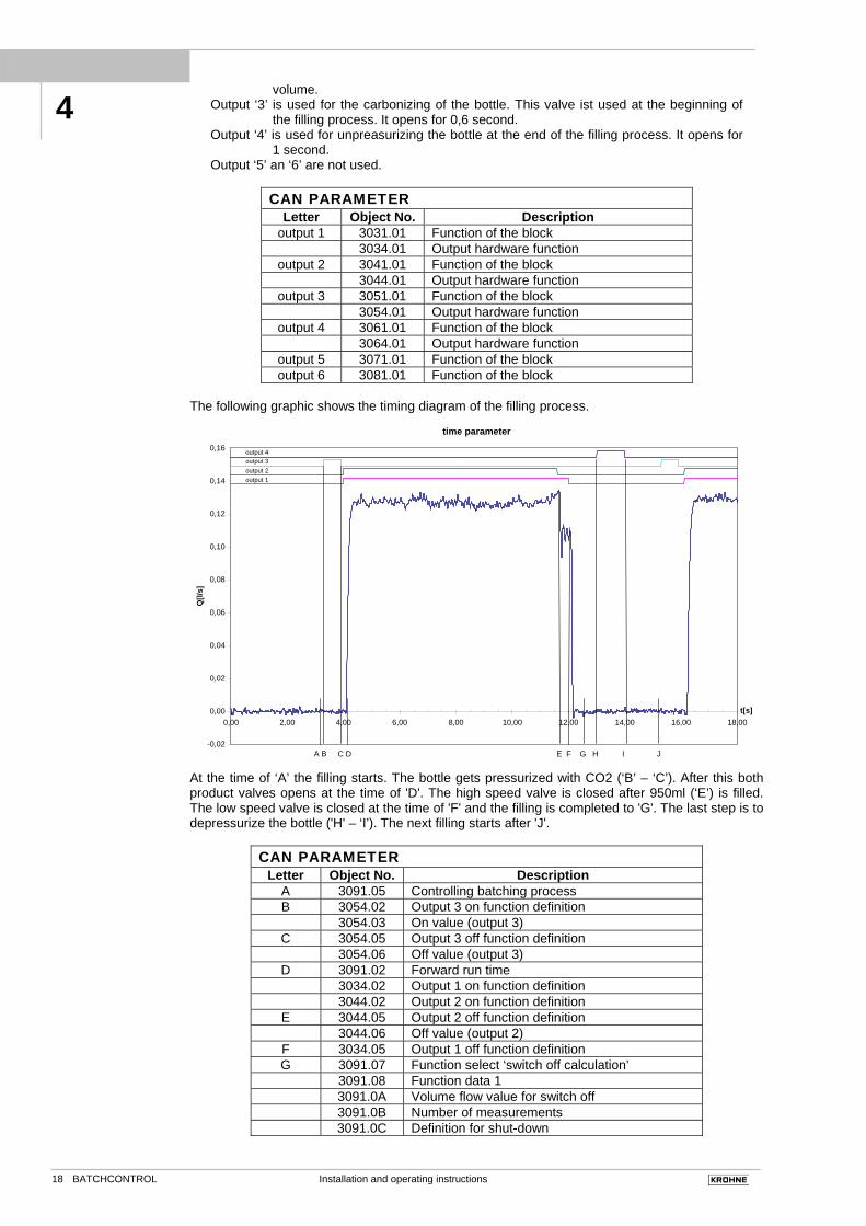
volume. Output ‘3’ is used for the carbonizing of the bottle. This valve ist used at the beginning of
the filling process. It opens for 0,6 second. Output ‘4’ is used for unpreasurizing the bottle at the end of the filling process. It opens for
1 second. Output ‘5’ an ‘6’ are not used.
CAN PARAMETER
Letter Object No. Description output 1 3031.01 Function of the block
3034.01 Output hardware function output 2 3041.01 Function of the block
3044.01 Output hardware function output 3 3051.01 Function of the block
3054.01 Output hardware function output 4 3061.01 Function of the block
3064.01 Output hardware function output 5 3071.01 Function of the block output 6 3081.01 Function of the block
The following graphic shows the timing diagram of the filling process.
At the time of ‘A’ the filling starts. The bottle gets pressurized with CO2 (‘B’ – ‘C’). After this both product valves opens at the time of 'D'. The high speed valve is closed after 950ml (‘E’) is filled. The low speed valve is closed at the time of 'F' and the filling is completed to 'G'. The last step is to depressurize the bottle ('H' – ‘I’). The next filling starts after 'J'.
CAN PARAMETER Letter Object No. Description
A 3091.05 Controlling batching process B 3054.02 Output 3 on function definition 3054.03 On value (output 3)
C 3054.05 Output 3 off function definition 3054.06 Off value (output 3)
D 3091.02 Forward run time 3034.02 Output 1 on function definition 3044.02 Output 2 on function definition
E 3044.05 Output 2 off function definition 3044.06 Off value (output 2)
F 3034.05 Output 1 off function definition G 3091.07 Function select ‘switch off calculation’ 3091.08 Function data 1 3091.0A Volume flow value for switch off 3091.0B Number of measurements 3091.0C Definition for shut-down
4
Installation and operating instructions 19BATCHCONTROL
H 3064.02 Output 4 on function definition 3064.03 On value (output 4) I 3064.05 Output 4 off function definition 3064.06 Off value (output 4)
G – J 3091.03 Time out There are parameters similar as in the case of the time representation, for the supervision of the volume flow.
‘A’ is the full scale range of the flow meter. An overload of +50% is permitted. If the flow should get even bigger, then the value is limited to150%. The value 'B' is an emergency switch off value for the valve. The value 'C' corresponds to the maximum volume flow during the filling process.
CAN PARAMETER Letter Object No. Description
A 3001.01 Full scale range B 3003.01 Maximum volume flow C 3094.06 Maximum flow velocity
The internal volume counter adds up the measurement values. As in the case of the two previous representations the counter has own parameters.
At the time of ‘A’ the filling starts. The bottle gets pressurized with CO2. After this both valves open for the product at the time of 'B'. The valve reduces the flow speed at the position of 'C' and the
4
Installation and operating instructions 20 BATCHCONTROL
filling is completed to 'D'. The parameter ‘I’ is the switch point for lower speed and ‘H’ is the target volume. ‘E’, ‘F’ and ‘G’ are alarm and emergency shutoff values.
CAN PARAMETER Letter Object No. Description
B 3091.02 Forward run time E 3093.04 Maximum batching time F 3003.05 Maximum volume G 3093.01 Maximum tail volume H 3091.01 Target volume I 3044.06 Off value
As a rule, valves don't close directly and completely. It comes to vibrations if the liquid is suddenly stopped. The vibrating amount of liquid is measured. If the oscillation amplitude is in a programmable area for a predefined number of measuring, then the filling is regarded as ended. The following picture shows this process:
end of filling
-0,005
-0,003
-0,001
0,001
0,003
0,005
0,007
0,009
12,10 12,20 12,30 12,40 12,50t[s]
Q[l/
s]
flow min. value max. value
start againstart start again filling process finished
counter : 0 1 0 1 2 0 1 2 3 4 5
A
B
C
CAN PARAMETER Letter Object No. Description A + B 3091.0A Volume flow value for switch off
C 3091.0B Number of measurements In addition to the described functions alarm and emergency off functions can be programmed. The individual phases of the filling process, changes of state and the filling results can be sent by the device automatically. The Krohne configuration program represents a good summary of the possibilities for the BATCHCONTROL 5014C. If the possibilities shouldn't suffice, then customer specific functions can be down loaded in the device.
4
Installation and operating instructions 21BATCHCONTROL
Part C Service 5 Illustration of printed circuit board Please note! Do not open the housing of the BATCHCONTROL IFM 5014C. Danger of contamination with substances likely to destroy the moisture barrier of the electronic equipment (e.g. if CIP or SIP cleaned from the outside). Therefore, please contact your KROHNE Service engineer before you open the housing.
1 Cover, signal converter 2 Gasket 3 Electronic unit, signal converter 4 Housing, signal converter 5 Primary head 7 Printed circuit board 8 Plug connector power supply and pulse output 9 U-clamp terminal for functional ground 10 Fastening screws for cover 11 Guide collar, primary head 12 O-ring gasket 13 Special pipe flange 14 Stud bolt with lock washer, plain washer and nut
5
5
1112
1314
4
1
102
3
9
6
8
7
LED 1 LED 2
5
Installation and operating instructions 22 BATCHCONTROL
Part D Technical Data, block diagram and measuring principle
6 Technical data 6.1 Flow during filling, and fill volume
Meter size Optimum flowrate for filling Filling times > 1.5 s, filling volume .....
Ambient temperature Process temperature -25 to +40 °C / -13 to +104 °F -60 to +140 °C / -76 to +284 °F
-25 to +60 °C / -13 to +140 °F -60 to + 60 °C / -76 to +140 °F (information on higher provided on request) steam cleaning up to +150 °C / +302 °F (max. 1 hour)
Temperature shock resistance Temperature rising Temperature falling
sudden change ∆T = 120 °C = 216 °F ∆T = 90 °C = 162 °F Temperature gradient 1 K/s = 1.8 °F/s
Operating pressure 40 bar / 580 psig (10 bar / 145 psig for DN 15, 32 and 1/2", 11/4" with straight measuring tube)
Electrode design fused-in-place electrodes
Protection category IP 67, equivalent to NEMA 6 (EN 60 529/IEC 529) (overall device, incl. signal converter)
Materials of construction Housing stainless steel 1.4408 or 1.4404
Installation and operating instructions 23BATCHCONTROL
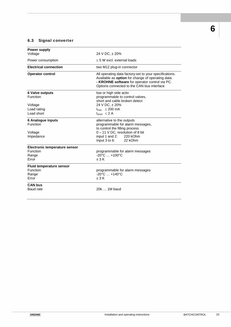
6.3 Signal converter Power supply Voltage 24 V DC, ± 20%
Power consumption ≤ 5 W excl. external loads
Electrical connection two M12 plug-in connector
Operator control All operating data factory-set to your specifications. Available as option for change of operating data: - KROHNE software for operator control via PC. Options connected to the CAN bus interface
6 Valve outputs low or high side activ Function programmable to control valves, short and cable broken detect Voltage 24 V DC, ± 20% Load rating Imax ≤ 200 mA
Load short Ishort ≤ 2 A
6 Analogue inputs alternative to the outputs Function programmable for alarm messages, to control the filling process Voltage 0 – 11 V DC, resolution of 8 bit Impedance input 1 and 2: 220 kOhm Input 3 to 6: 22 kOhm
Electronic temperature sensor Function programmable for alarm messages Range -20°C … +100°C Error ± 3 K
Fluid temperature sensor Function programmable for alarm messages Range -20°C … +140°C Error ± 3 K
CAN bus Baud rate 20k … 1M baud
6
Installation and operating instructions 24 BATCHCONTROL
6.4 Error limits at reference conditions F = Error in % of MV MV = measured value Pulse output DN 2.5 – 6 / 1/10“ – 1/4“ DN 10 – 40 / 3/8“ – 11/2“ at flow velocity of ... v ≥ 1 m/s ≥ 3.3 ft/s F < ± 0.5 % of MV F < ± 0.3 % of MV v < 1 m/s < 3.3 ft/s F < ± 0.4 % of MV + 1 mm/s F < ± 0.2 % of MV + 1 mm/s < ± 0.4 % of MV + 0.04 inch/s < ± 0.2 % of MV + 0.04 inch/s
Repeatability Filling time TF Standard deviation σ 1.5 s < TF ≤ 3 s ≤ 0.4 % 3.0 s < TF ≤ 5 s ≤ 0.2 % 5.0 s < TF ≤ 0.1 %
Reference conditions (similar to EN 29 104) Liquid product water +20 °C / +68 °F
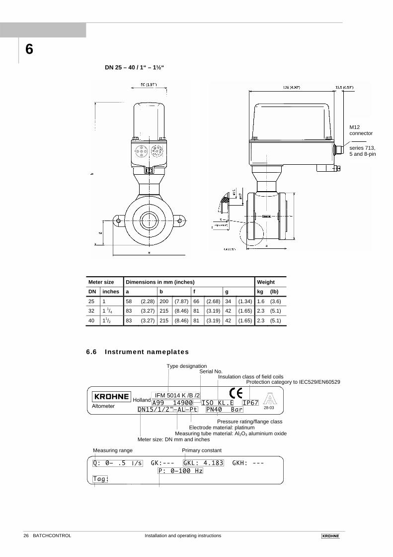
Type designation Serial No. Insulation class of field coils Protection category to IEC529/EN60529
Pressure rating/flange class Electrode material: platinum Measuring tube material: Al2O3 aluminium oxide Meter size: DN mm and inches
Measuring range Primary constant
28-03
IFM 5014 K /B /2
Installation and operating instructions 27BATCHCONTROL
7 Block diagram
The IFC 014 signal converter consists of 2 functional groups.
Functional group 1 contains an input amplifier, and a high-resolution analog/digital converter that is controlled and monitored by microprocessor CPU 1. It controlled also the direct current for the field coils of the primary head.
Functional group 2 is the batch controller board. It is supdevided in the six IO-function blocks, the CAN bus interface and the temperature sensors. All functions are controlled by the CPU 2.
Block diagram IFC 014
7
Installation and operating instructions 28 BATCHCONTROL
8 Measuring principle Flowmeter for electrically conductive liquids. Measurement is based on Faraday’s law of induction, according to which a voltage is induced in an electrically conductive body passing through a magnetic field.
The following expression applies: U = K × B × v × D K an instrument constant B magnetic field strength v mean velocity D tube diameter
Thus, the induced voltage is proportional to the mean flow velocity, when the field strength is constant. Inside the electromagnetic flowmeter, the liquid passes through a magnetic field applied perpendicular to the direction of flow. An electric voltage is induced by the movement of the liquid (which must have a minimum electrical conductivity), which is proportional to the mean flow velocity and thus to the volume of flow. The induced voltage signal is picked up by two electrodes that are in conductive contact with the liquid, and transmitted to a signal converter for a standardized output signal.
B U
U
D
v
8
Installation and operating instructions BATCHCONTROL
Part E Annex
E 1 Index
Keyword Section-No. Fct-No. A Ambient temperature 1.1, 6.2 B
Block diagram IFC 014 C 6, 7 C
Cleaning 1.3, 6.2 Connection diagrams – outputs 2.4 – power supply 2.3 Connection points – grounding 1.3.3 D
Data, Technical 6 Device description 1.4.1 DN = meter size in mm 6.1, 6.2 E
Electrical connection – outputs 2.4 – power supply 2.3 – status output 2.5 – current output 2.5 – pulse output 2.5 Electrodes 6.2, 8 Errors 1.2 Error (messages) 4.5 F
Factory settings 3.2 Fatal Error 3.1 FE = functional ground 5 Flanges 1.3 Flanges, Position of 1.3.1 Flow (Q) 1.1, 1.4.1, 4,
4.6, 6
Flow velocity v 4.4, 6.4, 8 Flow, direction of 1.2 Frequency output S – pulse output P 2.3.3, 4.4, 5.7 1.6
Functional description page 5 Function(s) 4.4 Functional ground FE 1.3.2, 2.1 – measuring range 6.6 H
Hardware info 4 I
Impulse output = pulse output P
(frequency output) 5.6 Instrument nameplates 6.6 L
Limits 1.1, 6.4 M
Measuring principle 6, 8 Measuring tube 1.1, 1.3 Meter size (DN) = nominal dia. of measuring tube in mm or 1.1, 1.5, 6.1, 3.2
6.2, 6.5 inches 1.5, 6.1, 6.5 Keyword Section-No. Fct-No. O
Operating pressure 11.3, 6.2 Option 1.5.2, 6.2,
6.3
P
P = pulse output 6.4 Power supply (= line voltage) 1.4.1, 2.3,
6.3
– frequency 2.2, 10.5 – power consumption 6.3 – voltage 6.3 Primary constant, see GKL 6.6 3.2 Primary head – installation 1.1 - 1.4 Process temperature 1.1, 6.2 Pulse output P / pulse width 5.6 1.6 Q
Q = flowrate 6.1 1.1, 3.2 R
Removal of – device (total) 1.4.1 S
Signal converter IFC 015 – operator control 6.3 – error limits 6.4 Software 4, 6.3 Start-up 3 Straight outlet run 1.1 Straight inlet run 1.1 Storage 1.1 Standards – ANSI . . . 1.3, – DIN . . . 1.3, – EN . . 2.2 – EMC page 4 – IEC . . . 1.1,1.3.3, 2.1, 6.2 – VDE . . . 1.3.3, 2.1, T
Technical data 6 – dimensions + weights 1.5.1, 6.5 – error limits 6.4 – limits for – signal converter IFC 015 K 6.3, 8 – primary head 1.1, 1.3.2,
1.4
Temperatures – ambient 1.1, 6.2 Totalizer (internal electronic) 4.6, 5.7 1.6 Transport 1.1 V
v = flow velocity 4.6, 4.7 3.2
E E
Installation and operating instructions 30 BATCHCONTROL
E 2 CAN parameter
Obj
ect N
o
Inde
x
Valu
e (d
efau
lt)
Des
crip
tion
Dim
ensi
on
Form
at
min
max
acce
ss
Des
crip
tor
tran
sfer
Des
crip
tion
10xxH CANopen parameter
1000H 00H Device type without long 0 r - - 0x00000014 (const. value)
1008H 00H Manufacturer Device Name without string - - r - - “IFC “
1009H 00H Manufacturer Hardware Version without string - - r - - “014 “
1010H Parameter save
1010H 00H 1 Number of entries without byte - - r - -
1010H 01H Save all parameters in EEPROM without long - - r/w - d Save databytes: 65H 76H 61H 73H
Read: 00H 00H 00H 01H 1011H Parameter recall
1011H 00H 1 Number of entries without byte - - r - -
1011H 01H 1 Recall all parameters from EEPROM to RAM without long - - r/w - d
1017H 00H 250 Consumer heartbeat time ms word 0 65535 r/w - d
1018H Identity Object
1018H 00H 4 Number of entries without byte - - r - -
1018H 01H Vendor Id without long - - r - -
1018H 02H Product code without long - - r - -
1018H 03H Revisionsnumber without long - - r - -
1018H 04H Serialnumber without long - - r - - 300xH Flow sensor parameter
3001H Sensor parameter
3001H 00H 7 Number of entries without byte - - r - -
3001H 01H 1 Full scale range l/s float 0,0015 15,1 r/w - d Full scale value, basis for values given as percentage values
3001H 02H 1 Time constant S float 0,1 99 r/w - as Time constant for output value, of no significance for BATCHCONTROL
3001H 03H 15 Meter size mm float 2,5 40 r/w - as Meter size of tube
3001H 04H 3,3 Sensor constant without float 0,5 9,9 r/w - as Calibration constant of Sensor
3001H 05H 0 Zero point l/s float -1,0 +1,0 r/w - as Zero point of Sensor
3001H 06H 0 Flow direction without byte 0 1 r/w - as 0 = as printed on instrument
1 = contrary to imprint
3001H 07H 0 Auto zero function - byte 0 1 r/w - d Zero point calculation
Bit 0: Activation of function
1 = function active
0 = function switched off
3002H Measurement values and PDO definition 3002H 00H 6 Number of entries without byte - - r - -
3002H 01H 0,0 Volume flow without time constant l/s float -15,1 15,1 r 01H - Actual measurement flow value
without time constant
3002H 02H 4 Sending function for Index 01H without byte 0 4 r/w - d Sending function measurement
value without time constant Bit 1-0: Priority
00 = PDO 0
01 = PDO 1
10 = PDO 2
11 = PDO 3
Bit 2: Activation of function
E
Installation and operating instructions BATCHCONTROL
Obj
ect N
o
Inde
x
Valu
e (d
efau
lt)
Des
crip
tion
Dim
ensi
on
Form
at
min
max
acce
ss
Des
crip
tor
tran
sfer
Des
crip
tion
1 = no message output
0 = activation of message output
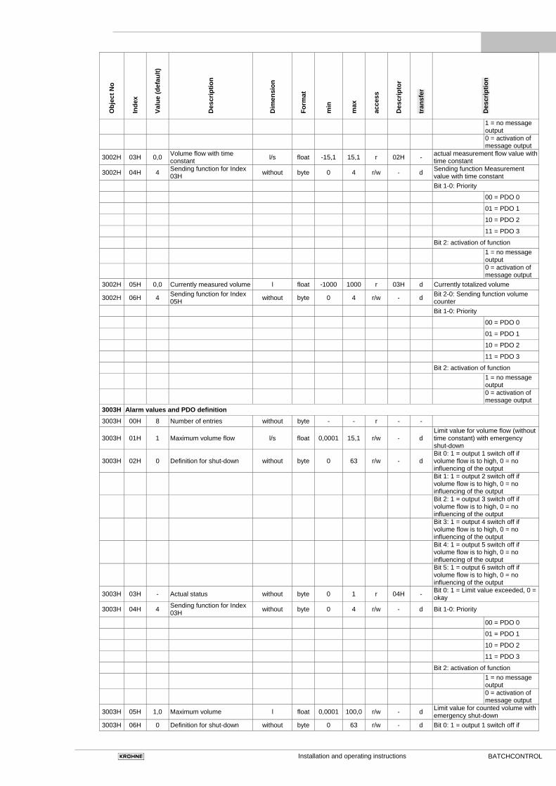
3002H 03H 0,0 Volume flow with time constant l/s float -15,1 15,1 r 02H - actual measurement flow value with
time constant
3002H 04H 4 Sending function for Index 03H without byte 0 4 r/w - d Sending function Measurement
value with time constant Bit 1-0: Priority
00 = PDO 0
01 = PDO 1
10 = PDO 2
11 = PDO 3
Bit 2: activation of function
1 = no message output
0 = activation of message output
3002H 05H 0,0 Currently measured volume l float -1000 1000 r 03H d Currently totalized volume
3002H 06H 4 Sending function for Index 05H without byte 0 4 r/w - d Bit 2-0: Sending function volume
counter Bit 1-0: Priority
00 = PDO 0
01 = PDO 1
10 = PDO 2
11 = PDO 3
Bit 2: activation of function
1 = no message output
0 = activation of message output
3003H Alarm values and PDO definition 3003H 00H 8 Number of entries without byte - - r - -
3003H 01H 1 Maximum volume flow l/s float 0,0001 15,1 r/w - d Limit value for volume flow (without time constant) with emergency shut-down
3003H 02H 0 Definition for shut-down without byte 0 63 r/w - d Bit 0: 1 = output 1 switch off if volume flow is to high, 0 = no influencing of the output
Bit 1: 1 = output 2 switch off if volume flow is to high, 0 = no influencing of the output
Bit 2: 1 = output 3 switch off if volume flow is to high, 0 = no influencing of the output
Bit 3: 1 = output 4 switch off if volume flow is to high, 0 = no influencing of the output
Bit 4: 1 = output 5 switch off if volume flow is to high, 0 = no influencing of the output
Bit 5: 1 = output 6 switch off if volume flow is to high, 0 = no influencing of the output
3003H 03H - Actual status without byte 0 1 r 04H - Bit 0: 1 = Limit value exceeded, 0 = okay
3003H 04H 4 Sending function for Index 03H without byte 0 4 r/w - d Bit 1-0: Priority
00 = PDO 0
01 = PDO 1
10 = PDO 2
11 = PDO 3
Bit 2: activation of function
1 = no message output
0 = activation of message output
3003H 05H 1,0 Maximum volume l float 0,0001 100,0 r/w - d Limit value for counted volume with emergency shut-down
3003H 06H 0 Definition for shut-down without byte 0 63 r/w - d Bit 0: 1 = output 1 switch off if
Installation and operating instructions 32 BATCHCONTROL
Obj
ect N
o
Inde
x
Valu
e (d
efau
lt)
Des
crip
tion
Dim
ensi
on
Form
at
min
max
acce
ss
Des
crip
tor
tran
sfer
Des
crip
tion
volume is to high, 0 = no influencing of the output
Bit 1: 1 = output 2 switch off if volume is to high, 0 = no influencing of the output
Bit 2: 1 = output 3 switch off if volume is to high, 0 = no influencing of the output
Bit 3: 1 = output 4 switch off if volume is to high, 0 = no influencing of the output
Bit 4: 1 = output 5 switch off if volume is to high, 0 = no influencing of the output
Bit 5: 1 = output 6 switch off if volume is to high, 0 = no influencing of the output
3003H 07H - Actual status without byte 0 1 r 05H - Bit 0: 1 = Limit value exceeded, 0 = okay
3003H 08H 4 Sending function for Index 07H without byte 0 4 r/w - d Bit 1-0: Priority
00 = PDO 0
01 = PDO 1
10 = PDO 2
11 = PDO 3
Bit 2: activation of function
1 = no message output
0 = activation of message output
301xH Electronic temperature sensor 3011H Sensor parameter 3011H 00H 2 Number of entries without byte - - r - -
3011H 01H 1.0 Factor for scaling without float 0,001 1000,0 r/w - d
3011H 02H 0.0 Offset for scaling °C float -100,0 100,0 r/w - d
3012H Measurement values and PDO definition
3012H 00H 3 Number of entries without byte - - r - -
3012H 01H 0,0 Measuring value °C float -10 +100 r 11H - actual measured temperature
3012H 02H 4 Sending function for index 01H without byte 0 4 r/w - d
Sending function of temperature output (repeat time depends on index 3)
Bit 1-0: Priority
00 = PDO 0
01 = PDO 1
10 = PDO 2
11 = PDO 3
Bit 2: activation of function
1 = no message output
0 = activation of message output
3012H 03H 250 Repeat time ms word 50 5000 r/w - d Repeat time for the value
3013H Alarm values and PDO definition 3013H 00H 4 Number of entries without byte - - r - -
3013H 01H 20 Lower limit value °C float -10 +80 r/w - d Warning message when value remains below limit
3013H 02H 70 Upper limit value °C float 0 +100 r/w - d Warning message when value exceeds limit
3013H 03H 0 Status of measuring input without byte 0 15 r 12H - Bit 0: 1 = lower limit value is exceeded
Bit 1: 1 = upper limit value is exceeded
Bit 2: 1 = sensor cable break
Bit 3: 1 = sensor short circuit
3013H 04H 4 Sending function for index 03H without byte 0 4 r/w - d Sending function change of status
Installation and operating instructions BATCHCONTROL
Obj
ect N
o
Inde
x
Valu
e (d
efau
lt)
Des
crip
tion
Dim
ensi
on
Form
at
min
max
acce
ss
Des
crip
tor
tran
sfer
Des
crip
tion
Bit 1-0: Priority
00 = PDO 0
01 = PDO 1
10 = PDO 2
11 = PDO 3
Bit 2: activation of function
0 = activation of message output
1 = no message output
302xH Liquid temperature sensor
3021H Sensor parameter 3021H 00H 2 Number of entries without byte - - r - -
3021H 01H 1.0 Factor for scaling without float 0,001 1000 r/w - d
3021H 02H 0.0 Offset for scaling °C float -100,0 100,0 r/w - d
3022H Measurement values and PDO definition 3022H 00H 3 Number of entries without byte - - r - -
3022H 01H 0,0 Measuring value °C float -10 +150 r 21H - actual measured temperature
3022H 02H 4 Sending function for index 01H without byte 0 4 r/w - d
Sending function of temperature output (repeat time depends on index 3)
Bit 1-0: Priority
00 = PDO 0
01 = PDO 1
10 = PDO 2
11 = PDO 3
Bit 2: activation of function
1 = no message output
0 = activation of message output
3022H 03H 250 Repeat time ms word 50 5000 r/w - d Repeat time for the value
3023H Alarm values and PDO definition
3023H 00H 4 Number of entries without byte - - r - -
3023H 01H 20 Lower limit value °C float -10 +140 r/w - d Warning message when value remains below limit
3023H 02H 70 Upper limit value °C float 0 +150 r/w - d Warning message when value exceeds limit
3023H 03H 0 Status of measuring input without byte 0 15 r 22H - Bit 0: 1 = lower limit value is exceeded
Bit 1: 1 = upper limit value is exceeded
Bit 2: 1 = sensor cable break
Bit 3: 1 = sensor short circuit
3023H 04H 4 Sending function for index 03H without byte 0 4 r/w - d Sending function change of status
Bit 1-0: Priority
00 = PDO 0
01 = PDO 1
10 = PDO 2
11 = PDO 3
Bit 2: activation of function
0 = activation of message output
1 = no message output
30yxH Function blocks (3 <= y <= 8)
30y1H Function block definition 30y1H 00H 1 Number of entries without byte - - r - -
30y1H 01H 0 Function of the block without byte 0 5 r/w - D Bit 3 - 0: function definition
Installation and operating instructions 34 BATCHCONTROL
Obj
ect N
o
Inde
x
Valu
e (d
efau
lt)
Des
crip
tion
Dim
ensi
on
Form
at
min
max
acce
ss
Des
crip
tor
tran
sfer
Des
crip
tion
0000 = off
0001 = binary input
0010 = analogue input
0011 = binary output
0100 = pulse width modulated output
0101 = customer program
30y2H Binary input parameter and PDO definition (only valid if 30y1.1 = 01H) 30y2H 00H 4 Number of entries without byte - - r - -
30y2H 01H 0 Function of Input without byte 0 20 r/w - D Bit 3 - 0: Function of Input
0000 = without function (off)
0001 = Start of batching
0010 = Stop of batching (emergency shut-down)
0011 = Input for Bus
0100 = customer program
Bit 4: Polarity of Input
0 = high active
1 = low active
30y2H 02H 0 Definition for shut-down without byte 0 63 r/w - d Bit 0: 1 = output 1 switch off if input is high, 0 = no influencing of the output
Bit 1: 1 = output 2 switch off if input is high, 0 = no influencing of the output
Bit 2: 1 = output 3 switch off if input is high, 0 = no influencing of the output
Bit 3: 1 = output 4 switch off if input is high, 0 = no influencing of the output
Bit 4: 1 = output 5 switch off if input is high, 0 = no influencing of the output
Bit 5: 1 = output 6 switch off if input is high, 0 = no influencing of the output
30y2H 03H 0 Status of Input without byte 0 1 r y1H - Bit 0: actual status of Input
0 = Input is off
1 = Input is on
30y2H 04H 4 Sending function for Index 03H without byte 0 4 r/w - d Bit 3-0: Sending function change of
status Bit 1-0: Priority
00 = PDO 0
01 = PDO 1
10 = PDO 2
11 = PDO 3
Bit 2: activation of function
1 = no message output
0 = activation of message output
30y3H Analogue input and PDO definition (only valid if 30y1.1 = 02H)
30y3H 00H 10 Number of entries without byte - - r - -
30y3H 01H 0 Function of Input without byte 0 20 r/w - d Bit 3 - 0: Function of Input
0000 = without function (off)
0001 = input for bus
Installation and operating instructions BATCHCONTROL
Obj
ect N
o
Inde
x
Valu
e (d
efau
lt)
Des
crip
tion
Dim
ensi
on
Form
at
min
max
acce
ss
Des
crip
tor
tran
sfer
Des
crip
tion
0010 = start of batching
0011 = stop of batching (emergency shut-down)
0100 = customer program
Bit 4: Calculation function
0 = input > parameter
1 = input < parameter
30y3H 02H 1,0 Scaling factor for analogue input without float 0,0001 1000 r/w - as The measured analogue voltage [V]
is multiplied with this factor
30y3H 03H 0,0 Scaling offset for analogue input V float -1000 1000 r/w - as
The offset is added to the measured analogue voltage [V] (voltage = offset + factor*real voltage)
30y3H 04H 0,0 Measured voltage (with scaling) V float 0,0 1000 r y2H - actual measured voltage
30y3H 05H 4 Sending function for Index 04H without byte 0 4 r/w - d Sending function of analogue value
(repeat time depends on index 6) Bit 1-0: Priority
00 = PDO 0
01 = PDO 1
10 = PDO 2
11 = PDO 3
Bit 2: activation of function
1 = no message output
0 = activation of message output
30y3H 06H 250 Repeat time ms word 50 5000 r/w - d Repeat time for the value
30y3H 07H 10 Maximum voltage V float 0,0001 12,0 r/w - d Limit value for voltage with emergency shut-down
30y3H 08H 0 Definition for shut-down without byte 0 63 r/w - d Bit 0: 1 = output 1 switch off if voltage is to high, 0 = no influencing of the output
Bit 1: 1 = output 2 switch off if voltage is to high, 0 = no influencing of the output
Bit 2: 1 = output 3 switch off if voltage is to high, 0 = no influencing of the output
Bit 3: 1 = output 4 switch off if voltage is to high, 0 = no influencing of the output
Bit 4: 1 = output 5 switch off if voltage is to high, 0 = no influencing of the output
Bit 5: 1 = output 6 switch off if voltage is to high, 0 = no influencing of the output
30y3H 09H 0 Actual status without byte 0 1 r y3H - Bit 0: 1 = Limit value exceeded, 0 = okay
30y3H 0AH 4 Sending function for Index 09H without byte 0 4 r/w - d Bit 1-0: Priority
00 = PDO 0
01 = PDO 1
10 = PDO 2
11 = PDO 3
Bit 2: activation of function
1 = no message output
0 = activation of message output
30y4H Binary output parameter and PDO definition (only valid if 30y1.1 = 03H)
30y4H 00H 9 Number of entries without byte - - r - -
30y4H 01H 0 Output hardware function without byte 0 3 r/w - d Bit 0: definition for high or low side driver
0 = output switching to
Installation and operating instructions 36 BATCHCONTROL
Obj
ect N
o
Inde
x
Valu
e (d
efau
lt)
Des
crip
tion
Dim
ensi
on
Form
at
min
max
acce
ss
Des
crip
tor
tran
sfer
Des
crip
tion
ground
1 = output switching to +24V
Bit1: output polarity
0 = high active
1 = low active
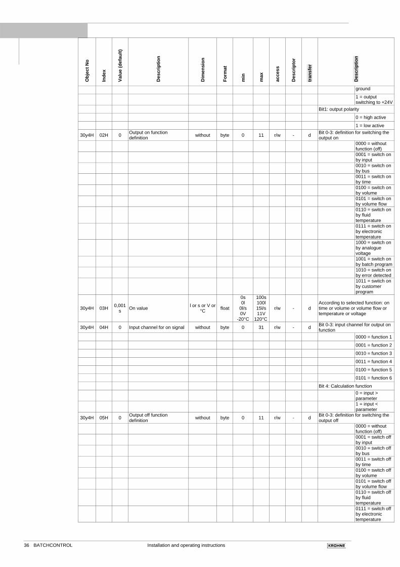
30y4H 02H 0 Output on function definition without byte 0 11 r/w - d Bit 0-3: definition for switching the
output on
0000 = without function (off)
0001 = switch on by input
0010 = switch on by bus
0011 = switch on by time
0100 = switch on by volume
0101 = switch on by volume flow
0110 = switch on by fluid temperature
0111 = switch on by electronic temperature
1000 = switch on by analogue voltage
1001 = switch on by batch program
1010 = switch on by error detected
1011 = switch on by customer program
30y4H 03H 0,001s On value l or s or V or
°C float
0s 0l
0l/s 0V
-20°C
100s 100l 15l/s 11V
120°C
r/w - d According to selected function: on time or volume or volume flow or temperature or voltage
30y4H 04H 0 Input channel for on signal without byte 0 31 r/w - d Bit 0-3: input channel for output on function
0000 = function 1
0001 = function 2
0010 = function 3
0011 = function 4
0100 = function 5
0101 = function 6
Bit 4: Calculation function
0 = input > parameter
1 = input < parameter
30y4H 05H 0 Output off function definition without byte 0 11 r/w - d Bit 0-3: definition for switching the
output off
0000 = without function (off)
0001 = switch off by input
0010 = switch off by bus
0011 = switch off by time
0100 = switch off by volume
0101 = switch off by volume flow
0110 = switch off by fluid temperature
0111 = switch off by electronic temperature
Installation and operating instructions BATCHCONTROL
Obj
ect N
o
Inde
x
Valu
e (d
efau
lt)
Des
crip
tion
Dim
ensi
on
Form
at
min
max
acce
ss
Des
crip
tor
tran
sfer
Des
crip
tion
1000 = switch off by analogue voltage
1001 = switch off by batch program
1010 = switch off by error detected
1011 = switch off by customer program
30y4H 06H 0,001s Off value l or s or l/s
or V or °C float
0s 0l
0l/s 0V
-20°C
100s 100l 15l/s 11V
120°C
r/w - d According to selected function: off time or volume or volume flow or temperature or voltage
30y4H 07H 0 Input channel for off signal without byte 0 21 r/w - d Bit 0-3: input channel for output off function
0000 = function 1
0001 = function 2
0010 = function 3
0011 = function 4
0100 = function 5
0101 = function 6
Bit 4: Calculation function
0 = input > parameter
1 = input < parameter
30y4H 08H 0 Status of output without byte 0 7 r/w y4H - Bit 0: actual status of output
0 = output is off
1 = output is on
Bit 2-1: error status of output
00 = no error
01 = short circuit (only detected if output is on)
10 = interruption (only detected if output is on)
11 = chip temperature to high
30y4H 09H 4 Sending function for Index 08H without byte 0 4 r/w - d Bit 3-0: Sending function change of
status Bit 1-0: Priority
00 = PDO 0
01 = PDO 1
10 = PDO 2
11 = PDO 3
Bit 2: activation of function
1 = no message output
0 = activation of message output
309xH Batching
3091H Filling parameter 3091H 00H 15 Number of entries without byte - - r - d
3091H 01H 0,5 Target volume l float 0,0001 200 r/w - d Automatic output controls on this parameter
3091H 02H 0,02 Forward run time s float 0.01 10 r/w - d Time after starting, before opening of valve
3091H 03H 0,5 Time out s float 0.01 10 r/w - d Time after filling, before a new run instruction is accepted
3091H 04H 1 Counter control without byte 0 3 w - d Counter control (only active on manual control output))
Bit 0: Start/Stop Counter
0 = stop counter
Installation and operating instructions 38 BATCHCONTROL
Obj
ect N
o
Inde
x
Valu
e (d
efau
lt)
Des
crip
tion
Dim
ensi
on
Form
at
min
max
acce
ss
Des
crip
tor
tran
sfer
Des
crip
tion
1 = counter operates
Bit 1: Counter reset
0 = no function
1 = reset the counter
3091H 05H 0 Controlling batching process without byte 0 3 w - d
Bit 0: 1 = Start filling through bus, only at batching process = CAN Bus (0 = without function)
Bit 1: 1 = Stop filling through bus, independent from other inputs (0 = without function)
3091H 06H 0 Learning function - byte 0 3 r/w - d Self learning function
Bit 1-0: Activation of function
0 = function off
1 = not allowed
2 = function on, no other action
3 = function on and the next filling starts the self learning cycle
3091H 07H 0 Function select for ‘switch off calculation’ - byte 0 1 r/w - d
Programm select for switch off calculation 0 = switch off point depends from the last 1 to 5 tail volumes 1 = switch off point depends from the actual flow and the last 1 to 5 tail volumes
3091H 08H 0 Function data 1 - byte 0 5 r/w - d
First data for the function ‘switch off calculation’ Fct = 0: number of tail volumes for switch off calculation (1 to 5) Fct = 1: number of tail volumes for switch off calculation (1 to 5)
3091H 09H 0 Function data 2 - byte 0 255 r/w - d Second data for the function ‘switch off calculation’ (for future use)
3091H 0AH 0,001 Volume flow value for switch off l/s float 0 15,1 r/w - d
If the volume flow is lower then this value, the filling will stop after number of measurements
3091H 0BH 10 Number of measurements byte 1 100 r/w - d Parameter for the function 3091.10
3091H 0CH 0 Definition for shut-down without byte 0 63 r/w - d Bit 0: 1 = output 1 switch off if 3091_05 Bit 1 = 1 , 0 = no influencing of the output
Bit 1: 1 = output 2 switch off if 3091_05 Bit 1 = 1, 0 = no influencing of the output
Bit 2: 1 = output 3 switch off if 3091_05 Bit 1 = 1 , 0 = no influencing of the output
Bit 3: 1 = output 4 switch off if 3091_05 Bit 1 = 1, 0 = no influencing of the output
Bit 4: 1 = output 5 switch off if 3091_05 Bit 1 = 1, 0 = no influencing of the output
Bit 5: 1 = output 6 switch off if 3091_05 Bit 1 = 1, 0 = no influencing of the output
3091H 0DH 100 Fixed tail volume 1 ml byte 0 255 r/w - d this tail volume is used for the next filling (if the bit 4 is set in RPDO1) and after power on
3091H 0EH 100 Fixed tail volume 2 ml byte 0 255 r/w - d this tail volume is used for the next filling (if the bit 5 is set in RPDO1)
3091H 0FH 10 Percentage of target volume % byte 0 50 r/w - d this tail volume is used for the next
filling (if the bit 6 is set in RPDO1) 3092H Status values and PDO definition
3092H 00H 2 Number of entries without byte - - r - d
3092H 01H 0 Actual status of batching without byte 0 5 r 91H -
Bit 0-3: actual status of batching
0 = stop
Installation and operating instructions BATCHCONTROL
Obj
ect N
o
Inde
x
Valu
e (d
efau
lt)
Des
crip
tion
Dim
ensi
on
Form
at
min
max
acce
ss
Des
crip
tor
tran
sfer
Des
crip
tion
1 = wait
2 = fill
3 = tail
4 = pause
5 = break
Bit 4 - 7: not used
3092H 02H 4 Sending function for Index 01H without byte 0 4 r/w - D Sending function at change of
status Bit 1-0: Priority
00 = PDO 0
01 = PDO 1
10 = PDO 2
11 = PDO 3
Bit 2: Activation of function
1 = no message output
0 = activation of message output
3093H Alarm values and PDO definition
3093H 00H 20 Number of entries without r
3093H 01H 0,05 Maximum tail volume l float 0,0001 1,0 r/w - d Limit value tail volume, status info only
3093H 02H 0 Actual status without byte 0 1 r 92H - Bit 0: 1 = Limit value overstepped, 0 = okay
3093H 03H 4 Sending function for Index 02H without byte 0 4 r/w - d Sending function at change of
status Bit 1-0: Priority
00 = PDO 0
01 = PDO 1
10 = PDO 2
11 = PDO 3
Bit 2: Activation of function
1 = no message output
0 = activation of message output
3093H 04H 10 Maximum batching time s float 0,01 100 r/w - d Limit value for batching time with emergency shut-down
3093H 05H 0 Definition for shut-down without byte 0 63 r/w - d Bit 0: 1 = output 1 switch off if batching time is to high, 0 = no influencing of the output
Bit 1: 1 = output 2 switch off if batching time is to high, 0 = no influencing of the output
Bit 2: 1 = output 3 switch off if batching time is to high, 0 = no influencing of the output
Bit 3: 1 = output 4 switch off if batching time is to high, 0 = no influencing of the output
Bit 4: 1 = output 5 switch off if batching time is to high, 0 = no influencing of the output
Bit 5: 1 = output 6 switch off if batching time is to high, 0 = no influencing of the output
3093H 06H 0 Actual status without byte 0 1 r 93H - Bit 0: 1 = Limit value overstepped, 0 = okay
3093H 07H 4 Sending function for Index 06H without byte 0 4 r/w - d Sending function at change of
status Bit 1-0: Priority
00 = PDO 0
01 = PDO 1
10 = PDO 2
11 = PDO 3
Bit 2: Activation of function
1 = no message
Installation and operating instructions 40 BATCHCONTROL
Obj
ect N
o
Inde
x
Valu
e (d
efau
lt)
Des
crip
tion
Dim
ensi
on
Form
at
min
max
acce
ss
Des
crip
tor
tran
sfer
Des
crip
tion
output
0 = activation of message output
3093H 08H 0,3 Maximum tail time s float 0,005 10 r/w - d Limit value for the tail time, status info only
3093H 09H 0 Actual status without byte 0 1 r 94H - Bit 0: 1 = Limit value overstepped, 0 = okay
3093H 0AH 4 Sending function for Index 09H without byte 0 4 r/w - d Sending function at change of
status Bit 1-0: Priority
00 = PDO 0
01 = PDO 1
10 = PDO 2
11 = PDO 3
Bit 2: Activation of function
1 = no message output
0 = activation of message output
3093H 0BH 0,01 Maximum leakage volume l float 0,001 0,1 r/w - d Leakage volume between two batches, status info only
3093H 0CH 0 Actual status without byte 0 1 r 95H - Bit 0: 1 = limit value overstepped, 0 = okay
3093H 0DH 4 Sending function for Index 0CH without byte 0 4 r/w - d Sending function at change of
status Bit 1-0: Priority
00 = PDO 0
01 = PDO 1
10 = PDO 2
11 = PDO 3
Bit 2: Activation of function
1 = no message output
0 = activation of message output
3093H 0EH 0.002 Lower limit for volume flow l/s float -100 +100 r/w - d lower deviation of the set point
3093H 0FH 0 Actual status without byte 0 1 r A0H - Bit 0: 1 = limit value understepped, 0 = okay
3093H 10H 4 Sending function for Index 0FH without byte 0 4 r/w - d Sending function at change of
status Bit 1-0: Priority
00 = PDO 0
01 = PDO 1
10 = PDO 2
11 = PDO 3
Bit 2: activation of function
1 = no message output
0 = activation of message output
3093H 11H 0.002 Upper limit for volume flow l/s float -100 +100 r/w - d upper deviation of the set point
3093H 12H 0 Actual status without byte 0 1 r A1H - Bit 0: 1 = limit value overstepped, 0 = okay
3093H 13H 4 Sending function for Index 12H without byte 0 4 r/w - d Sending function at change of
status Bit 1-0: Priority
00 = PDO 0
01 = PDO 1
10 = PDO 2
11 = PDO 3
Bit 2: activation of function
1 = no message output
0 = activation of message output
3093H 14H 0 Reset emergency shut off without byte 0 1 w - d 0 = no action
Installation and operating instructions BATCHCONTROL
Obj
ect N
o
Inde
x
Valu
e (d
efau
lt)
Des
crip
tion
Dim
ensi
on
Form
at
min
max
acce
ss
Des
crip
tor
tran
sfer
Des
crip
tion
1 = all emergency flags will be reset
3094H Result of last batching and PDO definition
3094H 00H 15 Number of entries without byte - - r - -
3094H 01H 4 Sending function without byte 0 4 r/w - d Sending function batching results
Bit 1-0: Priority
00 = PDO 0
01 = PDO 1
10 = PDO 2
11 = PDO 3
Bit 2: activation of function
1 = no message output
0 = activation of message output
3094H 02H 0 Batching time s float 0 100 r 96H - Time for complete batch process
3094H 03H 0 Tail time s float 0 10 r 97H - Closure time of valve
3094H 04H 0 Batching volume l float 0 100 r 98H - Volume filled
3094H 05H 0 Tail volume l float 0 1 r 99H - Volume during closure time
3094H 06H 0 Max. flow velocity l/s float 0 15,1 r 9AH - Highest volume flow during filling
3094H 07H 0 Leakage volume l float 0 0,1 r 9BH - Volume between two fillings
3094H 08H 0.002 Lower limit for filling l float 0 10 r/w - d lower deviation of the set point
3094H 09H 0 Actual status without byte 0 1 r 9CH - Bit 0: 1 = limit value understepped, 0 = okay
3094H 0AH 4 Sending function for Index 09H without byte 0 4 r/w - d Sending function at change of
status Bit 1-0: Priority
00 = PDO 0
01 = PDO 1
10 = PDO 2
11 = PDO 3
Bit 2: activation of function
1 = no message output
0 = activation of message output
3094H 0BH 0.002 Upper limit for filling l float 0 10 r/w - d upper deviation of the set point
3094H 0CH 0 Actual status without byte 0 1 r 9DH - Bit 0: 1 = limit value overstepped, 0 = okay
3094H 0DH 4 Sending function for Index 0CH without byte 0 4 r/w - d Sending function at change of
status Bit 1-0: Priority
00 = PDO 0
01 = PDO 1
10 = PDO 2
11 = PDO 3
Bit 2: activation of function
1 = no message output
0 = activation of message output
3094H 0EH 0 Actual status without byte 0 1 r 9EH - Bit 0: 1 = filling finished
3094H 0FH 4 Sending function for index 0EH without byte 0 4 r/w - d Sending function at change of
status Bit 1-0: Priority
00 = PDO 0
01 = PDO 1
10 = PDO 2
11 = PDO 3
Bit 2: activation of function
1 = no message output
Installation and operating instructions 42 BATCHCONTROL
Obj
ect N
o
Inde
x
Valu
e (d
efau
lt)
Des
crip
tion
Dim
ensi
on
Form
at
min
max
acce
ss
Des
crip
tor
tran
sfer
Des
crip
tion
0 = activation of message output
3095H Statistic
3095H 00H 15 Number of entries without byte - - r - -
3095H 01H -3000 Range 1 µl Word -32700 32700 r/w - d First limit
3095H 02H -1500 Range 2 µl Word -32700 32700 r/w - d Second limit
3095H 03H -500 Range 3 µl Word -32700 32700 r/w - d Third limit
3095H 04H +500 Range 4 µl Word -32700 32700 r/w - d Fourth limit
3095H 05H +1500 Range 5 µl Word -32700 32700 r/w - d Fifth limit
3095H 06H +3000 Range 6 µl word -32700 32700 r/w - d Sixth limit
3095H 07H 0 Total number of fillings without word 0 65535 r/w - d Total number of fillings since the last reset
3095H 08H 0 Number of fillings 1 without word 0 65535 r/w - d Number of fillings with a volume lower than range 1
3095H 09H 0 Number of fillings 2 without word 0 65535 r/w - d Number of fillings with a volume between range 1 and range 2
3095H 0AH 0 Number of fillings 3 without word 0 65535 r/w - d Number of fillings with a volume between range 2 and range 3
3095H 0BH 0 Number of fillings 4 without word 0 65535 r/w - d Number of fillings with a volume between range 3 and range 4
3095H 0CH 0 Number of fillings 5 without word 0 65535 r/w - d Number of fillings with a volume between range 4 and range 5
3095H 0DH 0 Number of fillings 6 without word 0 65535 r/w - d Number of fillings with a volume between range 5 and range 6
3095H 0EH 0 Number of fillings 7 without word 0 65535 r/w - d Number of fillings with a volume higher than range 6
3095H 0FH 0 Reset statistic without byte 0 1 r - d Bit 0: 1 = reset all statistic results
30AxH CAN parameter
30A1H 00H 7 Baudrate without byte 0 7 r/w - as Bit 0 – 3:
0000 = 1MBaud
0001 = 800kBaud
0010 = 500kBaud
0011 = 250kBaud
0100 = 125kBaud
0101 = 100kBaud
0110 = 50kBaud
0111 = 20kBaud
30A2H 00H 127 Node ID without byte 1 127 r/w - as
30A3H 00H 0 Customer TPDO activation without byte 0 15 r/w - d Bit 0: 1 = customer TPDO1 activ (description see below)
Bit 1: 1 = customer TPDO2 activ (description see below)
Bit 2: 1 = customer TPDO3 activ (description see below)
Bit 3: 1 = customer TPDO4 activ (description see below)
30A4H 00H 0 Customer RPDO activation without byte 0 15 r/w - d Bit 0: 1 = customer RPDO1 activ (description see below)
Bit 1: 1 = customer RPDO2 activ (description see below)
Bit 2: 1 = customer RPDO3 activ (description see below)
Bit 3: 1 = customer RPDO4 activ (description see below)
32yxH Customer specific 1 bit memory (3 <= y <= 8) 32y1H 00H 8 Number of entries without byte - - r - -
32y1H 01H 0 Bit no 1 without byte 0 1 r/w - d 1. bit variable (this parameter use the same memory cell as 30y2.04)
32y1H 02H 0 Bit no 2 without byte 0 1 r/w - d 2. bit variable (this parameter use the same memory cell as 30y2.04)
32y1H 03H 0 Bit no 3 without byte 0 1 r/w - d 3. bit variable (this parameter use the same memory cell as 30y2.04)
32y1H 04H 0 Bit no 4 without byte 0 1 r/w - d 4. bit variable (this parameter use the same memory cell as 30y2.04)
32y1H 05H 0 Bit no 5 without byte 0 1 r/w - d 5. bit variable (this parameter use the same memory cell as 30y2.04)
Installation and operating instructions BATCHCONTROL
Obj
ect N
o
Inde
x
Valu
e (d
efau
lt)
Des
crip
tion
Dim
ensi
on
Form
at
min
max
acce
ss
Des
crip
tor
tran
sfer
Des
crip
tion
32y1H 06H 0 Bit no 6 without byte 0 1 r/w - d 6. bit variable (this parameter use the same memory cell as 30y2.04)
32y1H 07H 0 Bit no 7 without byte 0 1 r/w - d 7. bit variable (this parameter use the same memory cell as 30y2.04)
32y1H 08H 0 Bit no 8 without byte 0 1 r/w - d 8. bit variable (this parameter use the same memory cell as 30y2.04)
32y2H 00H 8 Number of entries without byte - - r - -
32y2H 01H 0 Bit no 9 without byte 0 1 r/w - d 9. bit variable (this parameter use the same memory cell as 30y3.01)
32y2H 02H 0 Bit no 10 without byte 0 1 r/w - d 10. bit variable (this parameter use the same memory cell as 30y3.01)
32y2H 03H 0 Bit no 11 without byte 0 1 r/w - d 11. bit variable (this parameter use the same memory cell as 30y3.01)
32y2H 04H 0 Bit no 12 without byte 0 1 r/w - d 12. bit variable (this parameter use the same memory cell as 30y3.01)
32y2H 05H 0 Bit no 13 without byte 0 1 r/w - d 13. bit variable (this parameter use the same memory cell as 30y3.01)
32y2H 06H 0 Bit no 14 without byte 0 1 r/w - d 14. bit variable (this parameter use the same memory cell as 30y3.01)
32y2H 07H 0 Bit no 15 without byte 0 1 r/w - d 15. bit variable (this parameter use the same memory cell as 30y3.01)
32y2H 08H 0 Bit no 16 without byte 0 1 r/w - d 16. bit variable (this parameter use the same memory cell as 30y3.01)
33yxH Customer specific 8 bit memory (3 <= y <= 8) 33y1H 00h 9 Number of entries without byte - - r - -
33y1H 01H 0 Data format without byte 0 255 r - - descriptor for data format bit n = 0: byte n = signed char, bit n = 1: byte n = unsigned char
33y1H 02H 0 Byte no 1 without byte -128 0
+127 255 r/w - -
1. byte (33y1.01) bit 0 = 0: signed char (this parameter use the same memory cell as 30y3.05) (33y1.01) bit 0 = 1: unsigned char
33y1H 03H 0 Byte no 2 without byte -128 0
+127 255 r/w - -
2. byte (33y1.01) bit 1 = 0: signed char (this parameter use the same memory cell as 30y3.08) (33y1.01) bit 1 = 1: unsigned char
33y1H 04H 0 Byte no 3 without byte -128 0
+127 255 r/w - -
3. byte (33y1.01) bit 2 = 0: signed char (this parameter use the same memory cell as 30y3.0A) (33y1.01) bit 2 = 1: unsigned char
33y1H 05H 0 Byte no 4 without byte -128 0
+127 255 r/w - -
4. byte (33y1.01) bit 3 = 0: signed char (this parameter use the same memory cell as 30y4.01) (33y1.01) bit 3 = 1: unsigned char
33y1H 06H 0 Byte no 5 without byte -128 0
+127 255 r/w - -
5. byte (33y1.01) bit 4 = 0: signed char (this parameter use the same memory cell as 30y4.02) (33y1.01) bit 4 = 1: unsigned char
33y1H 07H 0 Byte no 6 without byte -128 0
+127 255 r/w - -
6. byte (33y1.01) bit 5 = 0: signed char (this parameter use the same memory cell as 30y4.04) (33y1.01) bit 5 = 1: unsigned char
33y1H 08H 0 Byte no 7 without byte -128 0
+127 255 r/w - -
7. byte (33y1.01) bit 6 = 0: signed char (this parameter use the same memory cell as 30y4.05) (33y1.01) bit 6 = 1: unsigned char
33y1H 09H 0 Byte no 8 without byte -128 0
+127 255 r/w - -
8. byte (33y1.01) bit 7 = 0: signed char (this parameter use the same memory cell as 30y4.07) (33y1.01) bit 7 = 1: unsigned char
33y2H 00h 9 Number of entries without byte - - r - -
33y2H 01H 0 Data format without byte 0 255 r - - descriptor for data format bit n = 0: byte n = signed char, bit n = 1: byte n = unsigned char
33y2H 02H 0 Byte no 9 without byte -128 0
+127 255 r/w - -
9. byte (33y2.01) bit 0 = 0: signed char (this parameter use the same memory cell as 30y4.09) (33y2.01) bit 0 = 1: unsigned char
Installation and operating instructions 44 BATCHCONTROL
Obj
ect N
o
Inde
x
Valu
e (d
efau
lt)
Des
crip
tion
Dim
ensi
on
Form
at
min
max
acce
ss
Des
crip
tor
tran
sfer
Des
crip
tion
33y2H 03H 0 Byte no 10 without byte -128 0
+127 255 r/w - -
10. byte (33y2.01) bit 1 = 0: signed char (this parameter use the same memory cell as 30y5.01) (33y2.01) bit 1 = 1: unsigned char
33y2H 04H 0 Byte no 11 without byte -128 0
+127 255 r/w - -
11. byte (33y2.01) bit 2 = 0: signed char (this parameter use the same memory cell as 30y5.02) (33y2.01) bit 2 = 1: unsigned char
33y2H 05H 0 Byte no 12 without byte -128 0
+127 255 r/w - -
12. byte (33y2.01) bit 3 = 0: signed char (this parameter use the same memory cell as 30y5.03) (33y2.01) bit 3 = 1: unsigned char
33y2H 06H 0 Byte no 13 without byte -128 0
+127 255 r/w - -
13. byte (33y2.01) bit 4 = 0: signed char (this parameter use the same memory cell as 30y5.04) (33y2.01) bit 4 = 1: unsigned char
33y2H 07H 0 Byte no 14 without byte -128 0
+127 255 r/w - -
14. byte (33y2.01) bit 5 = 0: signed char (33y2.01) bit 5 = 1: unsigned char
33y2H 08H 0 Byte no 15 without byte -128 0
+127 255 r/w - -
15. byte (33y2.01) bit 6 = 0: signed char (33y2.01) bit 6 = 1: unsigned char
33y2H 09H 0 Byte no 16 without byte -127 0
+127 255 r/w - -
16. byte (33y2.01) bit 7 = 0: signed char (33y2.01) bit 7 = 1: unsigned char
34yxH Customer specific 16 bit memory (3 <= y <= 8)
34y1H 00h 9 Number of entries without byte - - r - -
34y1H 01H 0 Data format without byte 0 255 r - - descriptor for data format bit n = 0: byte n = signed int, bit n = 1: byte n = unsigned int
34y1H 02H 0 Word no 1 without word -32768 0
3276765535 r/w - -
1. word (34y1.01) bit 0 = 0: signed int (this parameter use the same memory cell as 30y3.06) (34y1.01) bit 0 = 1: unsigned int
34y1H 03H 0 Word no 2 without word -32768 0
3276765535 r/w - -
2. word (34y1.01) bit 1 = 0: signed int (this parameter use the same memory cell as 30y5.05) (34y1.01) bit 1 = 1: unsigned int
34y1H 04H 0 Word no 3 without word -32768 0
3276765535 r/w - -
3. word (34y1.01) bit 2 = 0: signed int (this parameter use the same memory cell as 30y3.02) (34y1.01) bit 2 = 1: unsigned int
34y1H 05H 0 Word no 4 without word -32768 0
3276765535 r/w - -
4. word (34y1.01) bit 3 = 0: signed int (this parameter use the same memory cell as 30y3.02) (34y1.01) bit 3 = 1: unsigned int
34y1H 06H 0 Word no 5 without word -32768 0
3276765535 r/w - -
5. word (34y1.01) bit 4 = 0: signed int (this parameter use the same memory cell as 30y3.03) (34y1.01) bit 4 = 1: unsigned int
34y1H 07H 0 Word no 6 without word -32768 0
3276765535 r/w - -
6. word (34y1.01) bit 5 = 0: signed int (this parameter use the same memory cell as 30y3.03) (34y1.01) bit 5 = 1: unsigned int
34y1H 08H 0 Word no 7 without word -32768 0
3276765535 r/w - -
7. word (34y1.01) bit 6 = 0: signed int (this parameter use the same memory cell as 30y3.07) (34y1.01) bit 6 = 1: unsigned int
34y1H 09H 0 Word no 8 without word -32768 0
3276765535 r/w - -
8. word (34y1.01) bit 7 = 0: signed int (this parameter use the same memory cell as 30y3.07) (34y1.01) bit 7 = 1: unsigned int
Installation and operating instructions BATCHCONTROL
Obj
ect N
o
Inde
x
Valu
e (d
efau
lt)
Des
crip
tion
Dim
ensi
on
Form
at
min
max
acce
ss
Des
crip
tor
tran
sfer
Des
crip
tion
35yxH Customer specific 32 bit memory (3 <= y <= 8) 35y1H 00h 6 Number of entries without byte - - r - -
35y1H 01H 0 Data format without byte 0 255 r - - descriptor for data format bit n = 0: byte n = long, bit n = 1: byte n = float
35y1H 02H 0 Long no 1 without long -2.1e9 -3.4e38
2.1e93.4e3
8 r/w - -
1. long (35y1.01) bit 0 = 0: long (this parameter use the same memory cell as 30y4.03) (35y1.01) bit 0 = 1: float
35y1H 03H 0 Long no 2 without long -2.1e9 -3.4e38
2.1e93.4e3
8 r/w - -
2. long (35y1.01) bit 1 = 0: long (this parameter use the same memory cell as 30y4.06) (35y1.01) bit 1 = 1: float
35y1H 04H 0 Long no 3 without long -2.1e9 -3.4e38
2.1e93.4e3
8 r/w - - 3. long (35y1.01) bit 2 = 0: long
(35y1.01) bit 2 = 1: float
35y1H 05H 0 Long no 4 without long -2.1e9 -3.4e38
2.1e93.4e3
8 r/w - - 4. long (35y1.01) bit 3 = 0: long
(35y1.01) bit 3 = 1: float
35y1H 06H 0 Long no 5 without long -2.1e9 -3.4e38
2.1e93.4e3
8 r/w - - 5. long (35y1.01) bit 4 = 0: long
(35y1.01) bit 4 = 1: float
3900H Software download
3900H 00H 1 Number of entries without byte - - r - -
Installation and operating instructions 46 BATCHCONTROL
E 3 Form to accompany returned device If you need to return flowmeters for testing or repair to KROHNE Your electromagnetic flowmeter • has been carefully manufactured and
tested • and volumetrically calibrated in one of the
world’s most accurate test rigs. If installed and operated in accordance with these operating instructions, your flowmeter will rarely present any problems. Should you nevertheless need to return a flowmeter for checkout or repair, please pay strict attention to the following points: Due to statutory regulations concerning protection of the environment and safeguarding the health and safety of our personnel, Krohne may only handle, test and repair returned flowmeters that have been in contact with liquids if it is possible to do so without risk to personnel and environment.
This means that KROHNE can only service your flowmeter if it is accompanied by a certificate in line with the following model confirming that the flowmeter is safe to handle. If the flowmeter has been operated with toxic, caustic, flammable or water-endangering liquids, you are kindly requested • to check and ensure, if necessary by
rinsing or neutralizing, that all cavities in the flowmeter are free from such dangerous substances. (Directions on how you can find out whether the primary head has to be opened and flushed out or neutralized are obtainable from KROHNE on request.)
• to enclose a certificate with the flowmeter confirming that the flowmeter is safe to handle and stating the liquid used.
KROHNE regret that they cannot service your flowmeter unless it is accompanied by such a certificate.
Printed Form sheet (suitable for copying) Company: ............................................................................ Address: ........................................... Department: ......................................................................... Name:............................................... Tel. No.: ............................................................................... The enclosed electromagnetic flowmeter Type: .......................... KROHNE Order No. or Series No.: ............................................................. has been operated with the following process liquid ............................................................................ Because this process liquid is water-endangering * / toxic * / caustic * / flammable * we have – checked that all cavities in the flowmeter are free from such substances * – flushed out and neutralized all cavities in the flowmeter * (* delete where not applicable) We confirm that there is no risk to man or environment through any residual liquid contained in the flowmeter. Date: ........................................................ Signature: ................................................................... Company stamp: