Batched Multi Triangulation Paolo Cignoni - ISTI - CNR * Fabio Ganovelli - ISTI - CNR Enrico Gobbetti - CRS4 † Fabio Marton - CRS4 Federico Ponchio - ISTI - CNR Roberto Scopigno - ISTI - CNR ABSTRACT The Multi Triangulation framework (MT) is a very general ap- proach for managing adaptive resolution in triangle meshes. The key idea is arranging mesh fragments at different resolution in a Directed Acyclic Graph (DAG) which encodes the dependencies between fragments, thereby encompassing a wide class of multires- olution approaches that use hierarchies or DAGs with predefined topology. On current architectures, the classic MT is however unfit for real-time rendering, since DAG traversal costs vastly dominate raw rendering costs. In this paper, we redesign the MT framework in a GPU friendly fashion, moving its granularity from triangles to precomputed optimized triangle patches. The patches can be con- veniently tri-stripped and stored in secondary memory to be loaded on demand, ready to be sent to the GPU using preferential paths. In this manner, central memory only contains the DAG structure and CPU workload becomes negligible. The major contributions of this work are: a new out-of-core multiresolution framework, that, just like the MT, encompasses a wide class of multiresolution structures; a robust and elegant way to build a well conditioned MT DAG by introducing the concept of V -partitions, that can encompass var- ious state of the art multiresolution algorithms; an efficient multi- threaded rendering engine and a general subsystem for the external memory processing and simplification of huge meshes. 1 I NTRODUCTION In recent years, the large entertainment and gaming market has resulted in major investments in commodity graphics chip tech- nology, leading to state-of-the-art programmable graphics units (GPUs) with greater complexity and computational density than current CPUs. Despite the already impressive performance of cur- rent graphics chips, both architectural considerations and the inher- ently parallel nature of graphics operations, suggest that this trend will not change, and GPU performance increase will continue to outpace CPU performance increase. However, our ability to generate models that vastly exceed the peak memory and processing capabilities of even the most powerful hardware is a constant in a number of application domains (see, e.g., 3D scanning [14], geometric modeling [24], and numerical simulation [18]), imposing the need for adaptive techniques. An important class of large scale 3D models is characterized by an extremely dense sampling, with lots of fine geometric details, accompanied by a moderate depth complexity. The amount of data contained in these models does not allow us neither to render them directly nor to keep them in the main memory. So we need both a level-of-detail strategy, to filter out as efficiently as possible the data that is not contributing to a partic- ular image, and an out-of-core strategy, to supply efficiently to the * ISTI-CNR, Via Moruzzi 1, 56124 Pisa Italy www: http://vcg.isti.cnr.it e-mail: [email protected]† CRS4, POLARIS Edificio 1, 09010 Pula, Italy www: http://www.crs4.it/ e-mail: [email protected]insufficient amount of main memory. These models require both multiresolution techniques, because the graphics architecture cannot sustain such amount of data, and out-of-core techniques, because the combination of out-of-core data management techniques, for handling datasets larger than main memory, with level-of-detail al- gorithms based on multiresolution structures, to filter out as effi- ciently as possible the data that is not contributing to a particular image. Typical examples of these kind of datasets are terrains and scanned models. Up until recently, the vast majority of view-dependent level- of-detail methods were based on multiresolution structures taking decisions at the triangle/vertex primitive level. This kind of ap- proaches involves a constant CPU workload for each triangle that with current GPU evolution makes the CPU the bottleneck of the whole rendering process. In other words classical multiresolution approaches are not able to choose what has to be rendered fast enough. Given the current hardware trends, this performance bot- tleneck is doomed to become more and more evident. To overcome this bottleneck and to fully exploit the capabili- ties of current graphics hardware is therefore necessary to select and send batches of geometric primitives to be rendered with just a few CPU instructions. Following this approach, various GPU oriented multiresolution structures have been recently proposed, based on the idea of moving the granularity of the representation from triangles to triangle patches [1, 3, 25]. The benefit of these approaches is that the needed per-triangle workload to extract a multiresolution model reduces by orders of magnitude, the small patches can be preprocessed and optimized off line for a more ef- ficient rendering and highly efficient retained mode graphics calls can be exploited for caching the current adaptive model in AGP or video memory. Recent work has shown that the vast performance increase in CPU/GPU communication results in greatly improved frame rates [1, 3, 25]. It must be said that changing multiresolution granularity reduces the model flexibility: In general, more triangles than necessary will rendered to achieve a given accuracy. On the other hand, the render- ing time does not depends linearly on the triangle count anymore. Instead, it is strongly influenced by how the triangles are organized in memory and sent to the graphics card. With this paper we generalize previous recent approaches by proposing a batched multiresolution framework based on the Multi- Triangulation (MT) [22]. The MT is a very general framework that encompasses a wide class of multiresolution algorithms, but, like the techniques proposed in the 90’s, it was originally designed to minimize the number of triangles to be rendered, at the expense of CPU time. In this paper, we redesign the MT in a GPU friendly fashion, by moving the granularity from triangles to optimized triangle patches, and by redefining the construction and rendering algorithm to work on external memory. As a result, we provide a new out-of-core mul- tiresolution scheme that, just like the MT, encompasses a wide class of construction and view-dependent extraction algorithms and that enables the interactive rendering of massive meshes on commod- ity platforms. Moreover, we introduce a novel robust technique to build a well conditioned multiresolution data structure, based on V -Partitions sequences.
Transcript
Batched Multi Triangulation
Paolo Cignoni - ISTI - CNR ∗ Fabio Ganovelli - ISTI - CNR Enrico Gobbetti - CRS4 † Fabio Marton - CRS4Federico Ponchio - ISTI - CNR Roberto Scopigno - ISTI - CNR
ABSTRACT
The Multi Triangulation framework (MT) is a very general ap-proach for managing adaptive resolution in triangle meshes. Thekey idea is arranging mesh fragments at different resolution in aDirected Acyclic Graph (DAG) which encodes the dependenciesbetween fragments, thereby encompassing a wide class of multires-olution approaches that use hierarchies or DAGs with predefinedtopology. On current architectures, the classic MT is however unfitfor real-time rendering, since DAG traversal costs vastly dominateraw rendering costs. In this paper, we redesign the MT frameworkin a GPU friendly fashion, moving its granularity from triangles toprecomputed optimized triangle patches. The patches can be con-veniently tri-stripped and stored in secondary memory to be loadedon demand, ready to be sent to the GPU using preferential paths. Inthis manner, central memory only contains the DAG structure andCPU workload becomes negligible. The major contributions of thiswork are: a new out-of-core multiresolution framework, that, justlike the MT, encompasses a wide class of multiresolution structures;a robust and elegant way to build a well conditioned MT DAG byintroducing the concept of V -partitions, that can encompass var-ious state of the art multiresolution algorithms; an efficient multi-threaded rendering engine and a general subsystem for the externalmemory processing and simplification of huge meshes.
1 INTRODUCTION
In recent years, the large entertainment and gaming market hasresulted in major investments in commodity graphics chip tech-nology, leading to state-of-the-art programmable graphics units(GPUs) with greater complexity and computational density thancurrent CPUs. Despite the already impressive performance of cur-rent graphics chips, both architectural considerations and the inher-ently parallel nature of graphics operations, suggest that this trendwill not change, and GPU performance increase will continue tooutpace CPU performance increase.
However, our ability to generate models that vastly exceed thepeak memory and processing capabilities of even the most powerfulhardware is a constant in a number of application domains (see,e.g., 3D scanning [14], geometric modeling [24], and numericalsimulation [18]), imposing the need for adaptive techniques.
An important class of large scale 3D models is characterized byan extremely dense sampling, with lots of fine geometric details,accompanied by a moderate depth complexity.
The amount of data contained in these models does not allowus neither to render them directly nor to keep them in the mainmemory. So we need both a level-of-detail strategy, to filter out asefficiently as possible the data that is not contributing to a partic-ular image, and an out-of-core strategy, to supply efficiently to the
insufficient amount of main memory.These models require both multiresolution techniques, because
the graphics architecture cannot sustain such amount of data, andout-of-core techniques, because
the combination of out-of-core data management techniques, forhandling datasets larger than main memory, with level-of-detail al-gorithms based on multiresolution structures, to filter out as effi-ciently as possible the data that is not contributing to a particularimage.
Typical examples of these kind of datasets are terrains andscanned models.
Up until recently, the vast majority of view-dependent level-of-detail methods were based on multiresolution structures takingdecisions at the triangle/vertex primitive level. This kind of ap-proaches involves a constant CPU workload for each triangle thatwith current GPU evolution makes the CPU the bottleneck of thewhole rendering process. In other words classical multiresolutionapproaches are not able to choose what has to be rendered fastenough. Given the current hardware trends, this performance bot-tleneck is doomed to become more and more evident.
To overcome this bottleneck and to fully exploit the capabili-ties of current graphics hardware is therefore necessary to selectand send batches of geometric primitives to be rendered with justa few CPU instructions. Following this approach, various GPUoriented multiresolution structures have been recently proposed,based on the idea of moving the granularity of the representationfrom triangles to triangle patches [1, 3, 25]. The benefit of theseapproaches is that the needed per-triangle workload to extract amultiresolution model reduces by orders of magnitude, the smallpatches can be preprocessed and optimized off line for a more ef-ficient rendering and highly efficient retained mode graphics callscan be exploited for caching the current adaptive model in AGP orvideo memory. Recent work has shown that the vast performanceincrease in CPU/GPU communication results in greatly improvedframe rates [1, 3, 25].
It must be said that changing multiresolution granularity reducesthe model flexibility: In general, more triangles than necessary willrendered to achieve a given accuracy. On the other hand, the render-ing time does not depends linearly on the triangle count anymore.Instead, it is strongly influenced by how the triangles are organizedin memory and sent to the graphics card.
With this paper we generalize previous recent approaches byproposing a batched multiresolution framework based on the Multi-Triangulation (MT) [22]. The MT is a very general framework thatencompasses a wide class of multiresolution algorithms, but, likethe techniques proposed in the 90’s, it was originally designed tominimize the number of triangles to be rendered, at the expense ofCPU time.
In this paper, we redesign the MT in a GPU friendly fashion, bymoving the granularity from triangles to optimized triangle patches,and by redefining the construction and rendering algorithm to workon external memory. As a result, we provide a new out-of-core mul-tiresolution scheme that, just like the MT, encompasses a wide classof construction and view-dependent extraction algorithms and thatenables the interactive rendering of massive meshes on commod-ity platforms. Moreover, we introduce a novel robust technique tobuild a well conditioned multiresolution data structure, based onV -Partitions sequences.
The original contribution of this is twofold: 1) a general mul-tiresolution framework (Sec. 3 4) capable of rendering large meshesat interactive rate that fully exploit GPU capabilities and encom-passes existing approaches (Section 5) 2) A general subsystem forhandling and modifying massive meshes in external memory, (Sec-tion 6) the system can be used for the out-of-core construction ofthe MT, for the efficient rendering of our multiresolution model, butalso usable for general purposes mesh healing and processing.
2 RELATED WORK
In this section, we briefly survey some of the extensive previouswork on the general subjects of mesh simplification, multiresolu-tion models, and selective refinement; we focus mainly on the as-pects most closely related to our work: being able to manage largemeshes in external memory and trying to group primitives together.
A common characteristic of most adaptive mesh generation tech-niques is that they spend a great deal of the rendering time to com-pute the view-dependent triangulation and to communicate the up-dates to the graphics board. For this reason, many authors haveproposed techniques to alleviate popping effects due to small trian-gle counts [4, 11] or to amortize construction costs over multipleframes [6, 10, 15], improving feedback frequency at the expense ofa (much) higher latency.
Our technique reduces instead the per-triangle workload by com-posing at run-time pre-assembled optimized surface patches, mak-ing it possible to employ the retained-mode rendering model in-stead of the less efficient direct rendering approach. The ideaof grouping together sets of triangles in order to alleviate theCPU/GPU bottleneck has already been the focus of a number ofapproaches.
HLOD [7] improves the classic LOD scene graph by providingmultiple precomputed levels of details not only for each model butalso for entire subtrees. In this approach, conformality of the tri-angulations between elements of the partition at different resolu-tions can be guaranteed only by leaving some of the boundariesunsimplified, with obvious scalability and quality problems. Someapproaches simply avoid dealing with this kind of problem, limit-ing themselves to filling the resulting cracks between patches withad hoc geometry [9], or moving to a complete mesh-less struc-ture [8, 23]
The first methods capable to producing adaptive conforming sur-faces by composing precomputed patches were designed for terrainrendering. RUSTIC [21] and CABTT [13] are extensions of theROAM [6] algorithm, in which subtrees of the ROAM bintree arecached and reused during rendering. A similar technique is alsopresented in [5] for generic meshes. BDAM [1] constructs a for-est of hierarchies of right triangles, in which each node is a generaltriangulation of a small surface region. These methods are efficientand crack-free, but are limited to 2.5D datasets.
The first approach able to guarantee an adaptive conforming sur-face for a massive mesh with an arbitrary topology has been pre-sented in the Adaptive TetraPuzzles approach [3] where, by exploit-ing a 3D tetrahedral embedding of the well-known right trianglehierarchy, the authors extend the results of the BDAM approachto general 3D meshes. A related approach has been presented inthe QuickVDR system [25]: the original massive model is parti-tioned in a hierarchical set of small patches (called clusters) thatare independently converted into progressive meshes and mergedbottom-up. Additional logic in the management of boundaries be-tween clusters is used to allow the simplification of some clusterboundaries while enforcing the conformality of the resulting mesh.It should be noted that this approach generates a DAG of dependen-cies between clusters, and thus the whole structure can be consid-ered a particular case of the our batched MT framework. Similarly,TetraPuzzles can also be considered a particular case of the MT
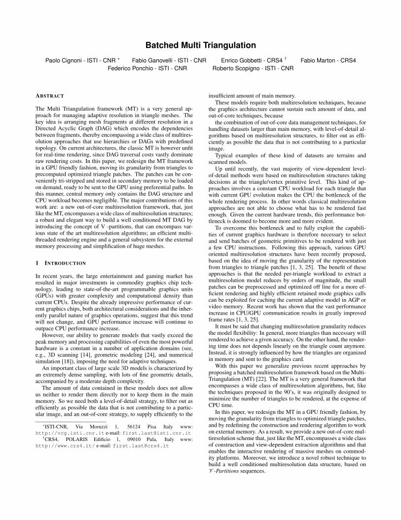
Figure 1: An example of the MT DAG that shows the one-to-one correspon-dence between the valid subsequences and the valid cuts. Note that the cutC2 (rendered in red) is not valid because two arc of the cut, a01 and a13, arein the same path from the source to the sink.
framework, in which all dependencies are implicitly encoded in thetetrahedral hierarchy.
3 RE-DESIGNING THE MT FOR MASSIVE MESHES
The Multi Triangulation framework (MT)[22] was designed as ageneral way to formalize and implement multiresolution modelsbased on simplicial complexes, but its basic concepts hold in a moregeneral context. In the following description we summarize the MTframework abstracting from the way the domain is represented andwe give conditions that should be satisfied for generating MT whoseDAG is not ill-conditioned and can guarantee good performancesand flexible adaptivity during extraction.
3.1 The MT Framework on general domains
Let us consider a domain Ω as the subset of R3 corresponding tothe surface to be represented. With the general term description wedenote all the primitives that can be used to describe this domain,e.g. triangulated surfaces, point sets, parametric surface etc..
Let Ω be our domain and D a description of Ω. The operation ofreplacing a portion f of D with a new description g, provided thatboth f and g describe the same part of the domain, is called pastingand it is formally written as: D⊕ g = D \ f ∪ g where f is calledfloor of g and g is called fragment.
A general simplification or refinement algorithm can be ex-pressed as the iteration of the following steps, starting with D0 = Dand i = 0 :
• select a region fi+1 ⊆ Di ;
• construct a new fragment gi+1 s.t. Ω( fi+1) = Ω(gi+1);
• update: Di+1 = Di⊕gi+1
If the fragment gi+1 is a description more accurate than its floor,then this is a refinement algorithm, otherwise it is a simplificationalgorithm.
When speaking about descriptions represented by a triangulationT we say that, after a pasting operation, T is conforming, or in otherwords correct, if for any pair of triangles in T their intersection is
either empty or it is coincident with a vertex or an edge of bothtriangles.
Note that gi+1 replaces its floor, which in turn could have beenintroduced by previous pasting operations. Therefore the floor ofgi+1 will be, in general, distributed among several fragments pastedbefore gi+1. Referring to Figure 1, the floor of g3 is distributedamong D0, g1 and g2 while the floor of g4 is all contained in g1.We will refer to this property saying that a fragment gi dependson the fragments intersecting its floor; e.g., referring to Fig. 1, g4depends on g3 while g3 depends on g1, D0 and g2.
Now consider the whole sequence of pasting operations pro-duced by the sequences of fragments S = (g1, . . . ,gn) and the corre-sponding description Dn = (((D0⊕g1)⊕g2)⊕ . . .)⊕ gn. Observethat a pasting Di⊕ gi+1 can be done if and only if Di contains thefloor of gi+1, in other words if S contains all fragments on whichgi+1 depends. This means that if we take a subsequence of S′ ⊆ Ssuch that for each fragment in S′ all the fragments on which itdepends are also in the subsequence (transitive closure of depen-dency), then S′ is also a sequence of valid pasting that will producea new representation, possibly different from Di∀i = 1..n. In the ex-ample D0⊕g2, D0⊕g1 and (D1⊕g1)⊕g4 are all valid descriptionsof the domain.
In the MT framework dependencies between fragments representa partial ordering and can be encoded in a directed acyclic graph(DAG) where fragments are the nodes. A closed subset (with re-spect to transitive closure of dependency) of the nodes of the DAG,corresponds to a valid sequence, and it is conveniently encoded witha cut on the DAG, i.e. the set of arcs leaving the specified portionof the DAG.
Note that, for completeness, all the leaf nodes containing por-tions that are not floor of any fragments are connected through anarc to a dummy sink node, so there is no node without leaving arcsexcept the dummy node, which is never included in a cut.
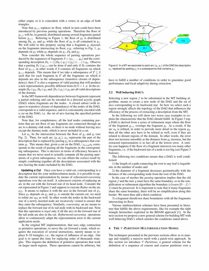
Let ai j be the intersection between the floor of g j and gi (seeFig. 2). Then, for each arc (gi,g j), ai j represents the part of thedescription that is replaced by pasting g j in a subsequence that con-tains gi. This means that, given a cut on the DAG, ∪k∈cutak corre-sponds to the result of pasting all the fragments in the correspond-ing subsequence. This is decisive in terms of efficiency because itmeans that we never need to actually compute all the pasting oper-ations of a given subsequence, we can obtain the correct result bysimply combining together all the descriptions associated with thearcs leaving the nodes included by the DAG.
Updating a Cut Once you have a valid cut, corresponding to adescription that fits your multiresolution needs, it is possible to up-date the current representation by means of refinement/coarseningoperations over the cut itself. A refinement consists of replacing anarc in the cut with the forward star of its head node. Consider thecut represented in Figure 1 and suppose to execute Refine on the arca23. It means to replace it with the arcs in the forward star of g3.Since g3 depends on g1 and g1 is outside the current cut, we needto refine arc a01 as well. In other words the nodes in the backwardstar of a newly inserted node are recursively visited to ensure thatthey enter the subsequence. Similarly, coarsening an arc means toreplace the forward star of its tail node with its backward star. Notethat this operation is legal only if all the arcs in the forward star ofthe tail node are also in the cut. Refinement/coarsening operationsallow to continuously adapt the representation error to the currentapplication needs.
In the original MT implementation, that uses edge contractionas primitive operations, to move the cut forward a node, which re-quires the execution of several instructions, merely means to re-place 8–10 triangles, i.e., the region of influence of an edge. Ourgoal is to spend this time for replacing order of thousands trian-gles. This requires the definition of primitive operations that workon larger mesh regions. These operations cannot be arbitrary, but
Figure 2: In a MT we associate to each arc (gi,g j) of the DAG the descriptionai j replaced by pasting g j in a subsequence that contains gi.
have to fulfill a number of conditions in order to guarantee goodperformance and local adaptivity during extraction.
3.2 Well behaving DAG’s
Selecting a new region f to be substituted in the MT building al-gorithm, means to create a new node of the DAG and the set ofarcs corresponding to its backward star. So how we select such aregion strongly affects the topology of the DAG that influences theefficiency of the process of extracting a description from the MT.
In the following we will show two worst case examples to ex-plain the characteristic that the DAG should fulfill. In Figure 3 top,a DAG is derived from a series of refinement steps where the floorof the fragment gi+1 overlaps the fragment gi. As a result, if thearc a4 is refined, in order to provide more detail in the region g4,then all the other arcs have to be refined as well, even if they arerelated to distant regions of the domain. In other words, the errordoes not increase smoothly as the distance from g4 increase, but theextracted representation is in fact all at the lowest error. A simi-lar case happens if the floor of a fragment intersects too many otherfragments, i.e. if the backward star of a node is too big (see Figure 3bottom).
The following two conditions ensure that a DAG is well condi-tioned:
1) the length of a path connecting the root to any leaf is logarith-mic in the number of nodes and
2) the diameter of a fragment decreases geometrically with thedistance of the corresponding node from the root of the DAG.
In the case of meshes the pasting operation implies that the oldregion f and the new g must have the same boundary, so in the sim-plification or refinement algorithm the boundary (closure(D− f )∩f ) must be preserved. It is important to note that if many fragmentsshare the same boundary, there will be no simplification along thisborder. We must then add a third condition:
3) a fragment should not share boundaries with all the fragmentsintersecting its floor.
Various multiresolution schemes have been presented in litera-ture that fulfills the above requirements, like for example the righttriangle hierarchies exploited in the BDAM approach [1]. In thenext section we propose a new general scheme for building MT withwell behaving DAG’s which satisfies the conditions stated above.
4 THE V -PARTITION MULTIRESOLUTION MODEL
The techniques presented in the previous sections allow us to man-age and simplify a massive mesh with a patch-wise approach. Inthis section we introduce V -Partitions, a general scheme for thedefinition of a sequence of coarser and coarser partitions over a
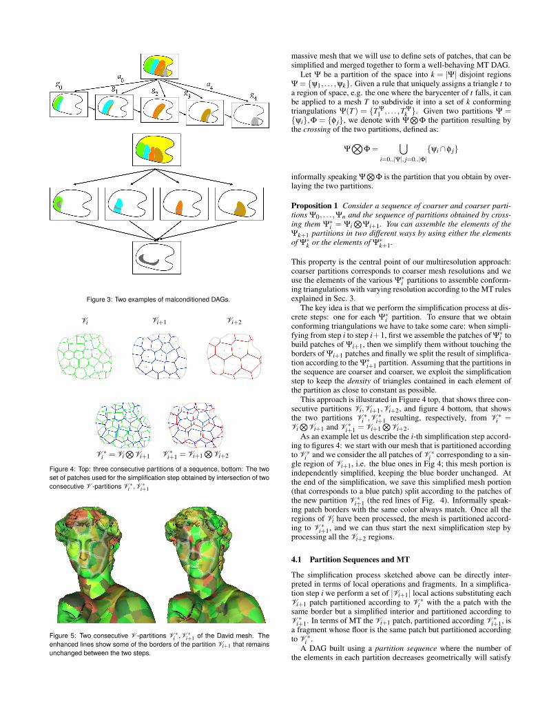
Figure 3: Two examples of malconditioned DAGs.
Vi Vi+1 Vi+2
V ∗i = Vi
NVi+1 V ∗
i+1 = Vi+1N
Vi+2
Figure 4: Top: three consecutive partitions of a sequence, bottom: The twoset of patches used for the simplification step obtained by intersection of twoconsecutive V -partitions V ∗
i ,V ∗i+1
Figure 5: Two consecutive V -partitions V ∗i ,V ∗
i+1 of the David mesh. Theenhanced lines show some of the borders of the partition Vi+1 that remainsunchanged between the two steps.
massive mesh that we will use to define sets of patches, that can besimplified and merged together to form a well-behaving MT DAG.
Let Ψ be a partition of the space into k = |Ψ| disjoint regionsΨ = ψ1, . . . ,ψk. Given a rule that uniquely assigns a triangle t toa region of space, e.g. the one where the barycenter of t falls, it canbe applied to a mesh T to subdivide it into a set of k conformingtriangulations Ψ(T ) = T Ψ
1 , . . . ,T Ψk . Given two partitions Ψ =
ψi,Φ = φ j, we denote with ΨN
Φ the partition resulting bythe crossing of the two partitions, defined as:
ΨO
Φ =[
i=0..|Ψ|, j=0..|Φ|ψi∩φ j
informally speaking ΨN
Φ is the partition that you obtain by over-laying the two partitions.
Proposition 1 Consider a sequence of coarser and coarser parti-tions Ψ0, . . . ,Ψn and the sequence of partitions obtained by cross-ing them Ψ∗
i = ΨiN
Ψi+1. You can assemble the elements of theΨk+1 partitions in two different ways by using either the elementsof Ψ∗
k or the elements of Ψ∗k+1.
This property is the central point of our multiresolution approach:coarser partitions corresponds to coarser mesh resolutions and weuse the elements of the various Ψ∗
i partitions to assemble conform-ing triangulations with varying resolution according to the MT rulesexplained in Sec. 3.
The key idea is that we perform the simplification process at dis-crete steps: one for each Ψ∗
i partition. To ensure that we obtainconforming triangulations we have to take some care: when simpli-fying from step i to step i+1, first we assemble the patches of Ψ∗
i tobuild patches of Ψi+1, then we simplify them without touching theborders of Ψi+1 patches and finally we split the result of simplifica-tion according to the Ψ∗
i+1 partition. Assuming that the partitions inthe sequence are coarser and coarser, we exploit the simplificationstep to keep the density of triangles contained in each element ofthe partition as close to constant as possible.
This approach is illustrated in Figure 4 top, that shows three con-secutive partitions Vi,Vi+1,Vi+2, and figure 4 bottom, that showsthe two partitions V ∗
i ,V ∗i+1 resulting, respectively, from V ∗
i =ViN
Vi+1 and V ∗i+1 = Vi+1
NVi+2.
As an example let us describe the i-th simplification step accord-ing to figures 4: we start with our mesh that is partitioned accordingto V ∗
i and we consider the all patches of V ∗i corresponding to a sin-
gle region of Vi+1, i.e. the blue ones in Fig 4; this mesh portion isindependently simplified, keeping the blue border unchanged. Atthe end of the simplification, we save this simplified mesh portion(that corresponds to a blue patch) split according to the patches ofthe new partition V ∗
i+1 (the red lines of Fig. 4). Informally speak-ing patch borders with the same color always match. Once all theregions of Vi have been processed, the mesh is partitioned accord-ing to V ∗
i+1, and we can thus start the next simplification step byprocessing all the Vi+2 regions.
4.1 Partition Sequences and MT
The simplification process sketched above can be directly inter-preted in terms of local operations and fragments. In a simplifica-tion step i we perform a set of |Vi+1| local actions substituting eachVi+1 patch partitioned according to V ∗
i with the a patch with thesame border but a simplified interior and partitioned according toV ∗
i+1. In terms of MT the Vi+1 patch, partitioned according V ∗i+1, is
a fragment whose floor is the same patch but partitioned accordingto V ∗
i .A DAG built using a partition sequence where the number of
the elements in each partition decreases geometrically will satisfy
condition 1. To satisfy condition 2 we need that the partition el-ements are distributed uniformly. In such a case the floor of eachfragment of Vi+1 intersects a roughly constant number of fragmentsof Vi and therefore the size of the backward star of a node will beroughly constant.
4.2 Building Partition Sequences using V -partitions
In practice we need to find an effective sequence of partitions thatwe can use to build our patch based MT. The sequence of parti-tions must be roughly uniform and coarser and coarser. It should benoted that the sequence of partitions does not need to adapt to thegeometric characteristics of the mesh (like curvature or density). Inthis approach the adaptivity is handled during the MT traversal. Ifa portion of the mesh presents more feature its simplification willyield an higher error and therefore during the MT traversal that por-tion will be maintained at a finer resolution.
We propose to build the partitioning using a Voronoi like ap-proach. Given a set of 3D points Q = v0, . . . ,vk, called seedset, we define the V -partition of a mesh T into patches VQ =QT
0 , . . . ,QTk by defining QT
i as the patch composed by the facesthat are nearest to the seed point vi. Note that it is not required forthese patches to be composed of a single connected component.
To build the multiresolution model, we need a sequence of seedsets Q0, . . .Qk, and the corresponding V -partitions V0 . . .Vk, of de-creasing granularity.
We propose two approaches for building the sequence of seedsets, the first one generates a regular partitioning while the secondone generates a sequence of irregular partitions.
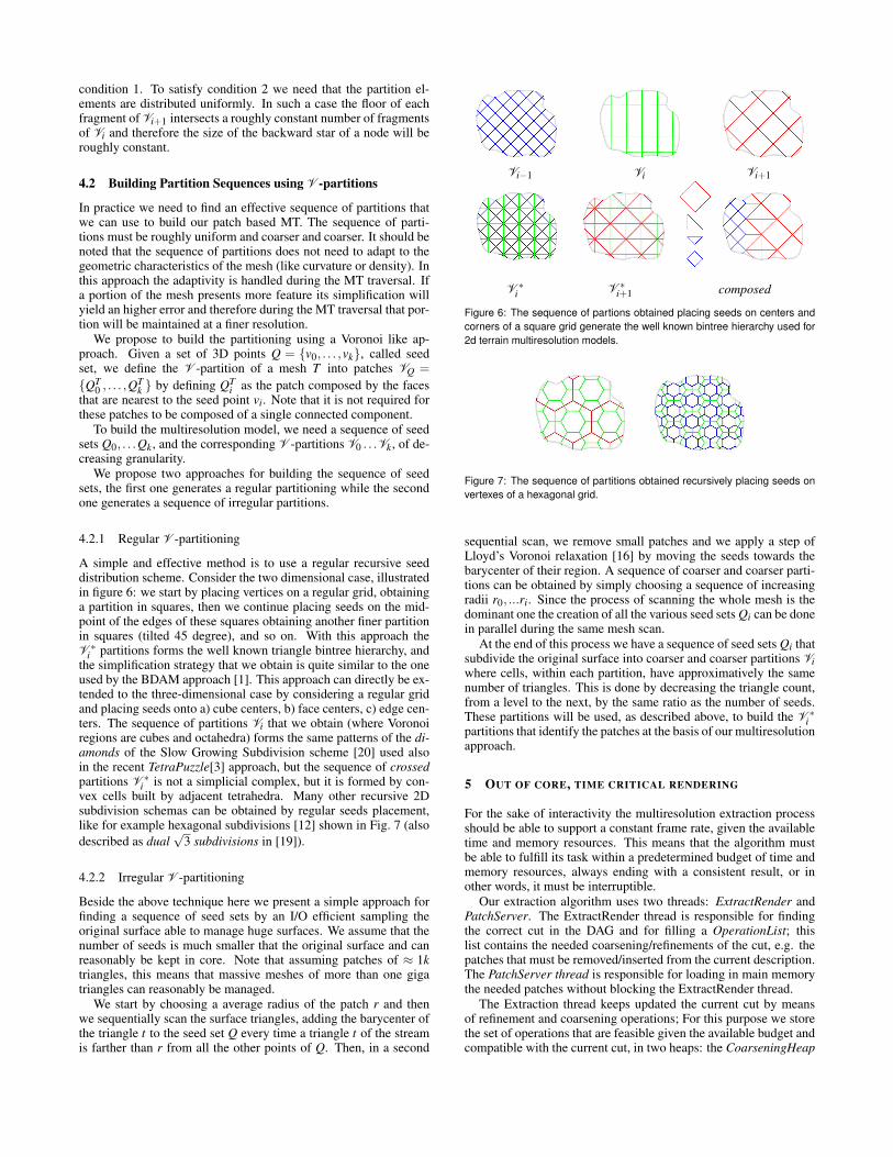
4.2.1 Regular V -partitioning
A simple and effective method is to use a regular recursive seeddistribution scheme. Consider the two dimensional case, illustratedin figure 6: we start by placing vertices on a regular grid, obtaininga partition in squares, then we continue placing seeds on the mid-point of the edges of these squares obtaining another finer partitionin squares (tilted 45 degree), and so on. With this approach theV ∗
i partitions forms the well known triangle bintree hierarchy, andthe simplification strategy that we obtain is quite similar to the oneused by the BDAM approach [1]. This approach can directly be ex-tended to the three-dimensional case by considering a regular gridand placing seeds onto a) cube centers, b) face centers, c) edge cen-ters. The sequence of partitions Vi that we obtain (where Voronoiregions are cubes and octahedra) forms the same patterns of the di-amonds of the Slow Growing Subdivision scheme [20] used alsoin the recent TetraPuzzle[3] approach, but the sequence of crossedpartitions V ∗
i is not a simplicial complex, but it is formed by con-vex cells built by adjacent tetrahedra. Many other recursive 2Dsubdivision schemas can be obtained by regular seeds placement,like for example hexagonal subdivisions [12] shown in Fig. 7 (alsodescribed as dual
√3 subdivisions in [19]).
4.2.2 Irregular V -partitioning
Beside the above technique here we present a simple approach forfinding a sequence of seed sets by an I/O efficient sampling theoriginal surface able to manage huge surfaces. We assume that thenumber of seeds is much smaller that the original surface and canreasonably be kept in core. Note that assuming patches of ≈ 1ktriangles, this means that massive meshes of more than one gigatriangles can reasonably be managed.
We start by choosing a average radius of the patch r and thenwe sequentially scan the surface triangles, adding the barycenter ofthe triangle t to the seed set Q every time a triangle t of the streamis farther than r from all the other points of Q. Then, in a second
Vi−1 Vi Vi+1
V ∗i V ∗
i+1 composed
Figure 6: The sequence of partions obtained placing seeds on centers andcorners of a square grid generate the well known bintree hierarchy used for2d terrain multiresolution models.
Figure 7: The sequence of partitions obtained recursively placing seeds onvertexes of a hexagonal grid.
sequential scan, we remove small patches and we apply a step ofLloyd’s Voronoi relaxation [16] by moving the seeds towards thebarycenter of their region. A sequence of coarser and coarser parti-tions can be obtained by simply choosing a sequence of increasingradii r0, ...ri. Since the process of scanning the whole mesh is thedominant one the creation of all the various seed sets Qi can be donein parallel during the same mesh scan.
At the end of this process we have a sequence of seed sets Qi thatsubdivide the original surface into coarser and coarser partitions Viwhere cells, within each partition, have approximatively the samenumber of triangles. This is done by decreasing the triangle count,from a level to the next, by the same ratio as the number of seeds.These partitions will be used, as described above, to build the V ∗
ipartitions that identify the patches at the basis of our multiresolutionapproach.
5 OUT OF CORE, TIME CRITICAL RENDERING
For the sake of interactivity the multiresolution extraction processshould be able to support a constant frame rate, given the availabletime and memory resources. This means that the algorithm mustbe able to fulfill its task within a predetermined budget of time andmemory resources, always ending with a consistent result, or inother words, it must be interruptible.
Our extraction algorithm uses two threads: ExtractRender andPatchServer. The ExtractRender thread is responsible for findingthe correct cut in the DAG and for filling a OperationList; thislist contains the needed coarsening/refinements of the cut, e.g. thepatches that must be removed/inserted from the current description.The PatchServer thread is responsible for loading in main memorythe needed patches without blocking the ExtractRender thread.
The Extraction thread keeps updated the current cut by meansof refinement and coarsening operations; For this purpose we storethe set of operations that are feasible given the available budget andcompatible with the current cut, in two heaps: the CoarseningHeap
Figure 8: Example of cut and corresponding heaps.
and the RefinementHeap.The priority in the heaps is given by the screen space error asso-
ciated with the operation: the first operation in the RefinementHeapis the feasible refinement with the largest screen space error, whilethe first in the CoarseningHeap is the coarsening with the small-est error that can be done on the current cut while maintaining thedesired screen space error.
The algorithm performs refinement operations until possible, andcoarsening operations otherwise. Whenever an operation is done,new operations will possibly be inserted in the heaps.
Figure 8 shows a cut example and the corresponding heaps. Forexample, if operation C4 (move the cut before the node g4) is per-formed C1 is inserted in the RefinementHeap and R8 is invalidated,since is no more feasible. Note that the inverse operation R4 wouldnow be feasible, but it would never been chosen and hence is noteven inserted.
Figure 9 shows the the algorithm ExtractRender thread. The ba-sic block of the algorithm is the estimation of the time needed toperform an operation, implemented in the function CheckBudget.
The time for the ExtractRender thread is the time for rendering,which is estimated as linearly proportional to the number of ren-dered triangles. Thus, for each operation (Pout ,Pin), we update thenumber of rendered triangles RT with RT = RT + |Pin|− |Pout | . IfRT exceeds the maximum number of triangles the operation cannotbe done.
Similarly, the PatchServer thread time is dominated by the timeneeded to load the patches from the disc. In the worst case, loadingtime is dominated by disk seek latency, that we assume bounded bya constant found by experiment.
The extraction algorithm always tries to apply the refinementwith the lowest error within the current budget; when the budgetdoes not allows it, it tries to apply the coarsening with the great-est error. The function AddToOperationsList inserts the operationpassed as argument in OperationList, which will be read by thePatchServer. Once Extraction is ended, OperationsList containsthe list of operations that can be done. The procedure Apply sim-ply runs through this list and performs the operations. To performan operation means to free the memory allocated for the patchesto be removed and to have the patches to be sent to the GPU inmain memory, which can require a loading from disk if they arenot already present. If the budget time ends before the whole list isscanned, which may happen if the time estimation was optimistic,then the algorithm returns and is guaranteed that the representationis conformal even if not to the required accuracy.
execute Perform on the operations in the heapsRefinementHeap and CoarseningHeap
Figure 9: Interruptible rendering cycle.
If there is still time after the execution of Apply, the remainingtime is used for pre-fetching the patches that will be probably usedin the next frame. At this stage, the pre-fetching strategy is verysimple and it consists of loading in memory the patches around thecurrent cut, which is easily achieved by applying all the operationsin the heaps.
5.1 View space and object space errors
In order to obtain a view-dependent multiresolution representationwhere the mesh resolution adapts with current viewing needs, weneed a view-dependent measure of the error. The screen space er-ror associated with a patch is derived at run time in a way sim-ilar to [1] using an object-space view-independent error measureand the bounding sphere of each patch. This object-space view-independent value is projected in screen space to obtain the error us-ing the bounding sphere. The relation between the error of the arcsof the graph is preserved by imposing that each bounding sphereencloses the bounding sphere of all the arcs in the subgraph.
Common measures used to quantify the error of a single patchare based on the Hausdorff distance between simplified and orig-inal mesh [1, 25, 3]. We have chosen a simpler strategy: we justuse the average edge length of the triangle of the patch. We madethis choice on the basis of the following considerations: the initialmeshes are dense and we use an highly accurate simplification al-gorithm which produce roughly uniform meshes; this means thatthe average edge length is monotonic along the levels of the DAG,as opposed to the Hausdorff distance based error which often needsto be corrected in order to respect the partial order among the nodeof the DAG: transform the average length of a triangle edge viewspace (in pixels units) and, given the fine tessellations created, thevisual fidelity is no more dominate by the geometric error but by thesurface shading, as observed in [17]. These considerations wereconfirmed using the geometric error computed during simplifica-tion with no noticeable difference.
Table 1: Numerical results for the construction of the MT (in minutes) thetime are relative to a small cluster of 4 pc’s.
6 A SUBSYSTEM TO HANDLE MASSIVE MESHES
Our framework requires an out-of-core mesh manager that allowsus to handle massive meshes patch by patch, reflecting the MT con-cept of local modification in terms of patches instead of triangles.The steps for the construction of the MT are: select a set of patches(the floor of a local modification e.g. all the patches composing anelement of the partition), load and modify the triangle mesh associ-ated with the patches, change the patch structure defining a new setof patches, and then save them.
Therefore we store the whole mesh as a collection of indepen-dent sub-meshes called patches. Each disk-stored patch contains anindexed representation of a small portion of the mesh with a copyof all the referenced vertices. Boundary vertices, that are shared be-tween patches, are replicated but identified for easier patch process-ing. For each patch p we maintain the list L of all the vertices thathave external dependencies. L entries are triplets (vp,q,vq), denot-ing, for each vertex vp in p, the patch q that refers to it and itsposition vq inside q.
When a set of patches P is requested for being processed andmodified in-core, we exploit these lists to efficiently unify vertexindexes and to mark the vertices that are referred by not loadedpatches. When the in-core mesh portion has to be written back,the user can change the mesh partitioning scheme, defining a newset of patches that covers the same mesh portion. In this case, wealso update the boundary lists of the patches that are not loaded butreferring to vertices in the current portion P.
Once you have a partition sequence, starting from the finer par-tition we have to load patches in memory, to simplify them and ef-fectively build the whole MT structure. Moreover with this schemeit is rather simple to perform out of core mesh healing processeslike smoothing and small hole filling.
Note that this approach it is somewhat independent from howpatches are actually stored. This allow to use the same structurealso for rendering purposes, just changing the final format of storedpatches. In this case for sake of rendering efficiency we can storepatches as optimized triangle strips, with precomputed normals andthen individually compressed using a quick decompression algo-rithm 1.
7 RESULTS AND DISCUSSION
The results presented in this section relate three dense meshes ofincreasing size: the Lucy (28M tri), the Michelangelo’s David (56Mtri) and Michelangelo’s S.Matthew (370M tri), all of them comingfrom the Stanford repository.
7.1 Preprocessing
The preprocessing was done on a cluster of PC’s on an Ethernet10Mb and 100Mb moderately loaded. The network speed resultedunimportant since the computation is dominated by the CPU timeto perform patch simplification, analogously to what reported byQDVR and Tetrapuzzles.
1we used the minilzo compression library available athttp://www.oberhumer.com/.
Since the number of triangles is halved at each iteration thenumber of triangles contained in the whole dataset is almost twicethan the number of original triangles, while, as can be seen inTable 1, the disk occupation of the MT is roughly 40% percenthigher than the original dataset. This should not be surprising,since the original mesh is in a raw format while all the MT patchesare stripified. These numbers are comparable to QVDR [25] whichrequires 13.992GB for the same S.Matthew model, and AdaptiveTetrapuzzles [3] (5.887 GB).
7.2 Rendering
The rendering performance was evaluated over several inspections,rotating and abruptly zooming in and out the model. All the testswere done with window size 800x600 on a Windows machineequipped with an AMD Athlon 64, 2 GHz, 512 MB Ram, SCSIhard disk, bus AGP 8x and graphics card GeForce 6800 GT. In allcases the in core memory limit to store all the patches was set toapprox. 90 MB. In the case of the S.Matthew model, this is lessthat 1% of the total data size, showing the effectiveness of the outof core data management strategy.
Our algorithm is able to render around 4M triangles per frame at35 fps with a pixel precision, computed as the average length of thetriangles projected onto the screen. The Adaptive Tetrapuzzles ap-proach sustains an average rendering rate of 70 millions of trianglesper second on a Linux equipped pc with a GeForce FX 5800 UltraGraphics, which should produce results comparable to our methodon the same hardware setting. QVDR, instead, sustains 771k trian-gles per frame at 17fps on a GeForce Ultra FX 5950 GPU, but alsoimplements occlusion culling which is not strictly necessary for thekind of meshes discussed in the paper.
8 CONCLUSION AND FUTURE WORK
We have presented a GPU friendly multiresolution framework pro-viding high visual quality as well as efficient rendering. The under-lying idea of the proposed method is to depart from current point- ortriangle-based multiresolution models and adopt a patch-based datastructure, from which view-dependent conforming mesh represen-tations are efficiently extracted and batched to the GPU by simplycombining precomputed patches.
Our main contributions are: a general framework for buildingefficient out-of-core multiresolution models that fully exploit thecapabilities of current consumer graphics hardware; a general out-of-core patch-based mesh management system on which the frame-work can be efficiently implemented; a parallel out-of-core, highquality, simplification algorithm; a proof-of-concept implementa-tions of novel multiresolution models that produce well conditionedmultiresolution structures and fit in the above framework.
The implementation of the framework proves it comparable, interms of speed and data preservation, to the ad-hoc state-of-the-artclustered multiresolution models it generalizes.
Figure 10: The Lucy model adaptively rendered with the batched MT.
Figure 11: The S. Matthew model adaptively rendered with the batched MT.
Although the current implementation gives satisfactory results,there are still issues that will require further work. The first is the in-corporation of an ad-hoc speculative pre-fetching of patches, whileat the present which patches are pre-fetched is not bound to thecamera movement. A second, more intriguing, goal is to efficientlyhandle the color information. At the present state, color coordi-nates can be assigned per-vertex basis and of course any techniqueto preserve this information during the simplification process (forexample [2]) can be adopted. Nonetheless, it is foreseeable that anad hoc solution complying the characteristics of our framework isneeded.
REFERENCES
[1] P. Cignoni, F. Ganovelli, E. Gobbetti, F.Marton, F. Ponchio, andR. Scopigno. BDAM: Batched dynamic adaptive meshes forhigh performance terrain visualization. Computer Graphics Forum,22(3):505–514, Sept. 2003.
[2] P. Cignoni, C. Montani, C. Rocchini, R. Scopigno, and M. Tarini. Pre-serving attribute values on simplified meshes by re-sampling detailtextures. Technical Report IEI-B4-37-12-98, IEI – C.N.R., Pisa, Italy,Dic. 1998.
[3] Paolo Cignoni, Fabio Ganovelli, Enrico Gobbetti, Fabio Marton, Fed-erico Ponchio, and Roberto Scopigno. Adaptive tetrapuzzles: efficientout-of-core construction and visualization of gigantic multiresolutionpolygonal models. ACM Trans. Graph., 23(3):796–803, 2004.
[4] Daniel Cohen-Or and Yishay Levanoni. Temporal continuity of levelsof detail in delaunay triangulated terrain. In IEEE Visualization ’96.IEEE, October 1996. ISBN 0-89791-864-9.
[5] Christopher DeCoro and Renato Pajarola. Xfastmesh: fast view-dependent meshing from external memory. In VIS ’02: Proceedingsof the conference on Visualization ’02, pages 363–370, Washington,DC, USA, 2002. IEEE Computer Society.
[6] M.A. Duchaineau, M. Wolinsky, D.E. Sigeti, M.C. Miller, C. Aldrich,and M.B. Mineev-Weinstein. ROAMing terrain: Real-time optimally
adapting meshes. In Proceedings IEEE Visualization ’97, pages 81–88. IEEE, October 1997.
[7] Carl Erikson, Dinesh Manocha, and William V. Baxter III. HLODsfor faster display of large static and dynamic environments. In Proc.SIGGRAPH, pages 111–120, 2001.
[8] E. Gobbetti and F. Marton. Layered point clouds – a simple and ef-ficient multiresolution structure for distributing and rendering gigan-tic point-sampled models. Computers & Graphics, 28(6), December2004.
[9] M. Guthe, P. Borodin, Á. Balázs, and R. Klein. Real-time appear-ance preserving out-of-core rendering with shadows. In A. Keller andH. W. Jensen, editors, Rendering Techniques 2004 (Proceedings ofEurographics Symposium on Rendering), pages 69–79 + 409. Euro-graphics Association, June 2004.
[10] H. Hoppe. View-dependent refinement of progressive meshes. InTurner Whitted, editor, SIGGRAPH 97 Conference Proceedings, An-nual Conference Series, pages 189–198. ACM SIGGRAPH, AddisonWesley, August 1997. ISBN 0-89791-896-7.
[11] H. Hoppe. Smooth view-dependent level-of-detail control and its apli-cations to terrain rendering. In IEEE Visualization ’98 Conf., pages35–42, 1998.
[12] Ioannis Ivrissimtzis, Malcolm Sabin, and Neil Dodgson. On thesupport of recursive subdivision. ACM Transactions on Graphics,23(4):1043–1060, 2004.
[13] Joshua Levenberg. Fast view-dependent level-of-detail rendering us-ing cached geometry. In Proceedings IEEE Visualization ’02, pages259–266. IEEE, Oct 2002.
[14] M. Levoy, K. Pulli, B. Curless, S. Rusinkiewicz, D. Koller, L. Pereira,M.Ginzton, S. Anderson, J. Davis, J. Ginsberg, J. Shade, and D. Fulk.The digital michelangelo project: 3D scanning of large statues. InSiggraph 2000,pages 131–144.
[15] Peter Lindstrom. Out-of-core construction and visualization of mul-tiresolution surfaces. In ACM 2003 Symposium on Interactive 3DGraphics, pages 93–102,239, April 2003.
[16] S. Lloyd. Least squares quantization in pcm. Information Theory,IEEE Transactions on, 28(2):129–137, 1982.
[17] Frank Losasso and Hugues Hoppe. Geometry clipmaps: terrain ren-dering using nested regular grids. ACM Transactions on Graphics,23(3):769–776, August 2004.
[18] A. A. Mirin, R. H. Cohen, B. C. Curtis, W. P. Dannevik, A. M. Dimits,M. A. Duchaineau, D. E. Eliason, D. R. Schikore, S. E. Anderson,D. H. Porter, P. R. Woodward, L. J. Shieh, and S. W. White. Veryhigh resolution simulation of compressible turbulence on the IBM-SPsystem. In Supercomputing ’99. .
[19] Peter Oswald and Peter Schroeder. Composite primal/dual√
[20] Valerio Pascucci. Slow growing subdivision (sgs) in any dimension:Towards removing the curse of dimensionality. Computer GraphicsForum, 21(3):451–460, September 2002.
[21] Alex A. Pomeranz. Roam using surface triangle clusters (rustic). Mas-ter’s thesis, University of California at Davis, 2000.
[22] E. Puppo. Variable resolution terrain surfaces. In Proceedings EightCanadian Conference on Computational Geometry, Ottawa, Canada,pages 202–210, August 12-15 1996.
[23] S. Rusinkiewicz and M. Levoy. QSplat: A multiresolution point ren-dering system for large meshes. In Comp. Graph. Proc., Annual Conf.Series (SIGGRAPH 00), pages 343–352. ACM Press, July 24-28 2000.
[24] Gokul Varadhan and Dinesh Manocha. Out-of-Core rendering of mas-sive geometric datasets. In Robert Moorhead, Markus Gross, and Ken-neth I. Joy, editors, Proc. of the 13th IEEE Visualization 2002 Confer-ence (VIS-02), pages 69–76. IEEE Computer Society, October 2002.
[25] Sung-Eui Yoon, Brian Salomon, Russell Gayle, and Dinesh Manocha.Quick-vdr: Interactive view-dependent rendering of massive models.In VIS ’04: Proceedings of the IEEE Visualization 2004 (VIS’04),pages 131–138. IEEE Computer Society, 2004.