22
Bath Systems 06.AR.15/4 GB September 2001 Assembling and Installation Instructions

Bath Systems
06.AR.15/4 GB September 2001
Assembling and Installation Instructions

© Arjo Hospital Equipment AB 2001
Arjo products are patented or patent pending. Patent information is available by contacting Arjo Hospital Equipment AB.
Our policy is one of continuous development, and we therefore reserve the right to make technical alterations without notice. The content of this publication may not be copied either whole or in part without the consent of Arjo Hospital Equipment AB.
3
Contents
Safety Precautions............................................................................ 4
Introduction...................................................................................... 5
Preparations...................................................................................... 6
Unpacking and assembling .............................................................. 7
Assembling of legs........................................................................... 9
Preparations for mounting of bathtub ............................................ 10
Mounting of drainage..................................................................... 11
Mounting of bathtub ...................................................................... 12
After mounting the bath tub........................................................... 14
Installation...................................................................................... 15
Equapotential bonding .................................................................................. 15
Loading ......................................................................................................... 15
Transport and Storage Conditions................................................................. 15
Electrical installation..................................................................................... 16
DIP Switches for Autofill.............................................................................. 16
Water installation .......................................................................................... 17
Water supply ................................................................................................. 17
Calibration of the thermostat mixer .............................................................. 17
Adjustable thermostat.................................................................................... 17
Drainage ........................................................................................................ 18
Level adjustment ........................................................................................... 18
Space Requirements ...................................................................................... 19
Technical specifications................................................................. 19
Measurements, Volume and Weight ............................................................. 19
Overall dimensions - Rhapsody bathtub ........................................ 20
Overall dimensions - Primo bathtub .............................................. 21
4
For the UK-market:
Regarding the thermostatic mixer,FMM5193-9011, a completing document (10.AR.02/1GB) should accompany this manual.
Make sure that the assembly is carried out:
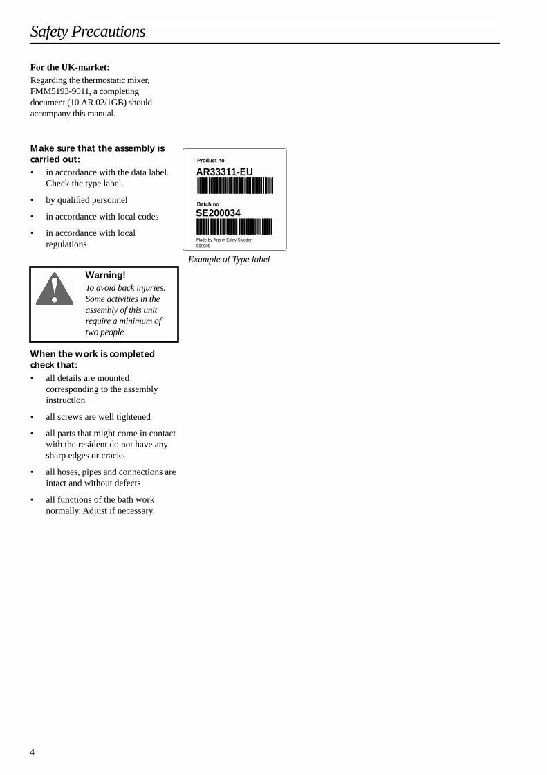
• in accordance with the data label.Check the type label.
• by qualified personnel
• in accordance with local codes
• in accordance with local regulations
When the work is completed check that:
• all details are mounted corresponding to the assemblyinstruction
• all screws are well tightened
• all parts that might come in contact with the resident do not have any sharp edges or cracks
• all hoses, pipes and connections are intact and without defects
• all functions of the bath worknormally. Adjust if necessary.
Safety Precautions
Product no
Batch no
AR33311-EU
SE200034
Made by Arjo in Eslov Sweden990909
Example of Type label
Warning!To avoid back injuries: Some activities in the assembly of this unit require a minimum oftwo people .

5
The Bath System is delivered in twoseparate boxes.
Box I contains the panel, legs, inside box, and bottles with liquids.
Optional: Footrest and pillow.
Box II contains the bath tub and cover.
Recommended tools
Electric screwdriver with extender+ Socket AF 13 mm+ Socket AF 10 mm+ Phillips bits
Torx key T30
Ring wrench AF 19 mm
Ring wrench AF 17 mm
Ring wrench AF 8 mm
U-wrench AF 24 mm
U-wrench AF 30 mm
Allen key 8 mm
Allen key 6 mm
Allen key 4 mm
Hammer
Screwdriver (for slotted screws)
Weight, net approx. 150 kg (331 lbs)
Total, approx. 180 kg (397 lbs)
Weight, net approx. 65 kg (143 lbs)
Total, approx. 130 kg (287 lbs)
Introduction
1
30
I
II

6
Check the contents of the inside box for stillbath delivered in two boxes.
A 1 panel lid
B 1 lock with key (optional)
C Attachment of lid; 3 screws, 6 washers, 3 lockable nuts
D 2 fillister head screws with washers
E 2 connection hoses(P100, Japan market: 3 hoses)
F 1 drain hose, complete(1 changeable hose applicable to wall drainage)
G Liquids (optional)
H For 2150 mm bathtub only:2 feet with covers 2 screws with washers and nuts
For hydromassage some contents are added. Check the added contents for hydromassage.
A 1 outlet nozzle
B 1 inlet nozzle
C 1 treatment hose (optional)
For hydrosound some contents are added (check the added contents for hydrosound).
A 1 transducer with equapotential bonding cable
B 1 cable
Preparations
E
C
F G
DA B
H
A B
C
A B

7
1 Undo the two screws on top of the case.
2 Remove the cover around the panel. Save the lid for use in the further mounting process.
3 Remove the legs from the package.
4 Remove the angle iron from the legs.
5 Undo the back cover of the panel. (6 screws and 2 nuts).
6 Unscrew the screws at the back and on the front wooden borders and remove them. Save for use in the further mounting process.
7 Remove the back plate of the frame.
8
Not applicable to model P100.
Connect to the electric current(temporary if necessary).See instructions for permanent installation on page 15.
Unpacking and assembling
1 2
3 4
5 6
7 8
8
9
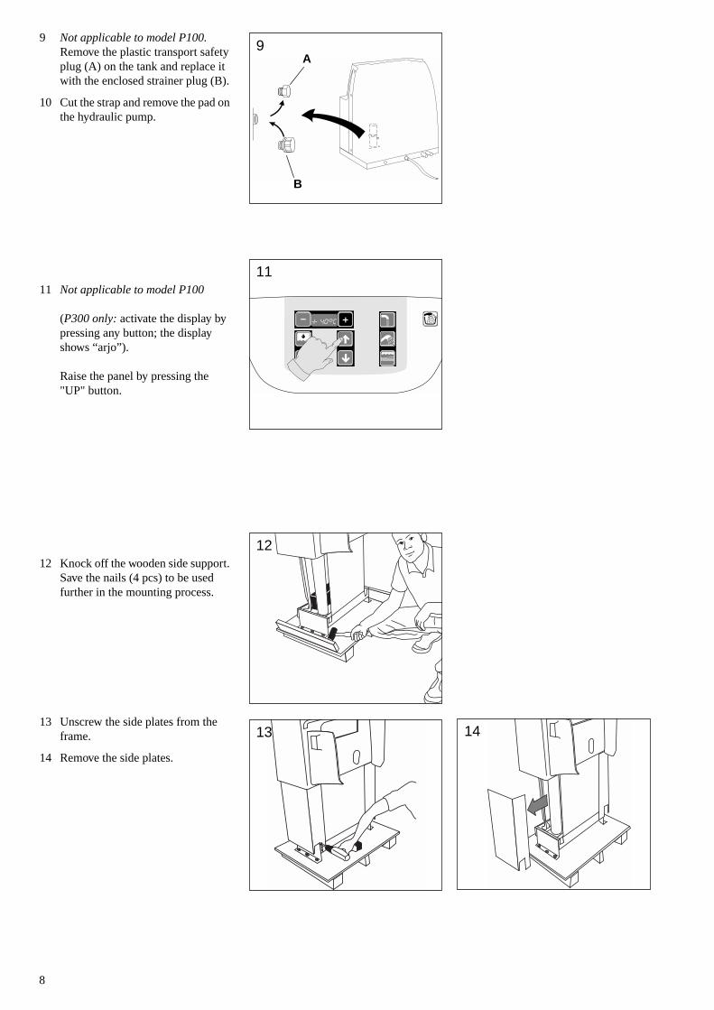
Not applicable to model P100.
Remove the plastic transport safety plug (A) on the tank and replace it with the enclosed strainer plug (B).
10 Cut the strap and remove the pad on the hydraulic pump.
11
Not applicable to model P100
(
P300 only:
activate the display by pressing any button; the display shows “arjo”
)
.
Raise the panel by pressing the "UP" button.
12 Knock off the wooden side support. Save the nails (4 pcs) to be used further in the mounting process.
13 Unscrew the side plates from the frame.
14 Remove the side plates.
9A
B
11
TERMOMETER
12
13 14
9
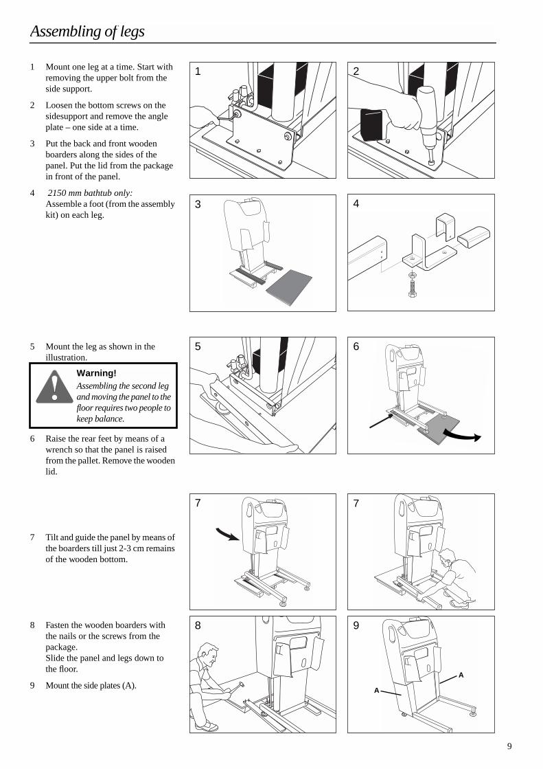
1 Mount one leg at a time. Start with removing the upper bolt from the side support.
2 Loosen the bottom screws on the sidesupport and remove the angle plate – one side at a time.
3 Put the back and front wooden boarders along the sides of the panel. Put the lid from the package in front of the panel.
4
2150 mm bathtub only:
Assemble a foot (from the assembly kit) on each leg.
5 Mount the leg as shown in theillustration.
6 Raise the rear feet by means of a wrench so that the panel is raised from the pallet. Remove the wooden lid.
7 Tilt and guide the panel by means of the boarders till just 2-3 cm remains of the wooden bottom.
8 Fasten the wooden boarders with the nails or the screws from the package. Slide the panel and legs down to the floor.
9 Mount the side plates (A).
Assembling of legs
1 2
3 4
5 6
Warning!Assembling the second leg and moving the panel to the floor requires two people to keep balance.
7 7
8 9
A
A

10
1 Make sure that the panel is in itstop position. Remove the rubber stoppers on the clamps.
2
(System with Hydromassage only)
:a/ Loosen the hoseclamps on the connections of the hydropump. b/ Fit the hydromassage nozzles.
3
(System with Hydrosound only):
Mounting of the transducer on the bath tub:
• Slide transducer into tub opening with connector facing down. Make sure that the lip of the gasket is seated against the tub all the way around the tub opening.
• While applying a force of 40-50 N to the face of the transducer, tighten the six M4 nuts with a maximum torque of 4 Nm.
4 Connect the hydrosound cable (A) to the transducer (B).
5 Check
that the transducer ground wire is properly fastened. Connect the transducer ground wire to the earth ground wires placed by the fixed mixer (C).
Preparations for mounting of bathtub
1
2a 2b
Gasket
Stud
Backing plate
Transducer Assy
M4 Nut (Qty 6)
Bath tub3
Warning!It is extremely important that the transducer serial number and the hydro-sound unit serial number match. To verify compati-bility, check the transdu-cer for its serial number. Then check the identifica-tion plate on the hydro-sound unit for its serial number. If the numbers do not match, do not install the Hydrosound system.
AB
C
4-5
11
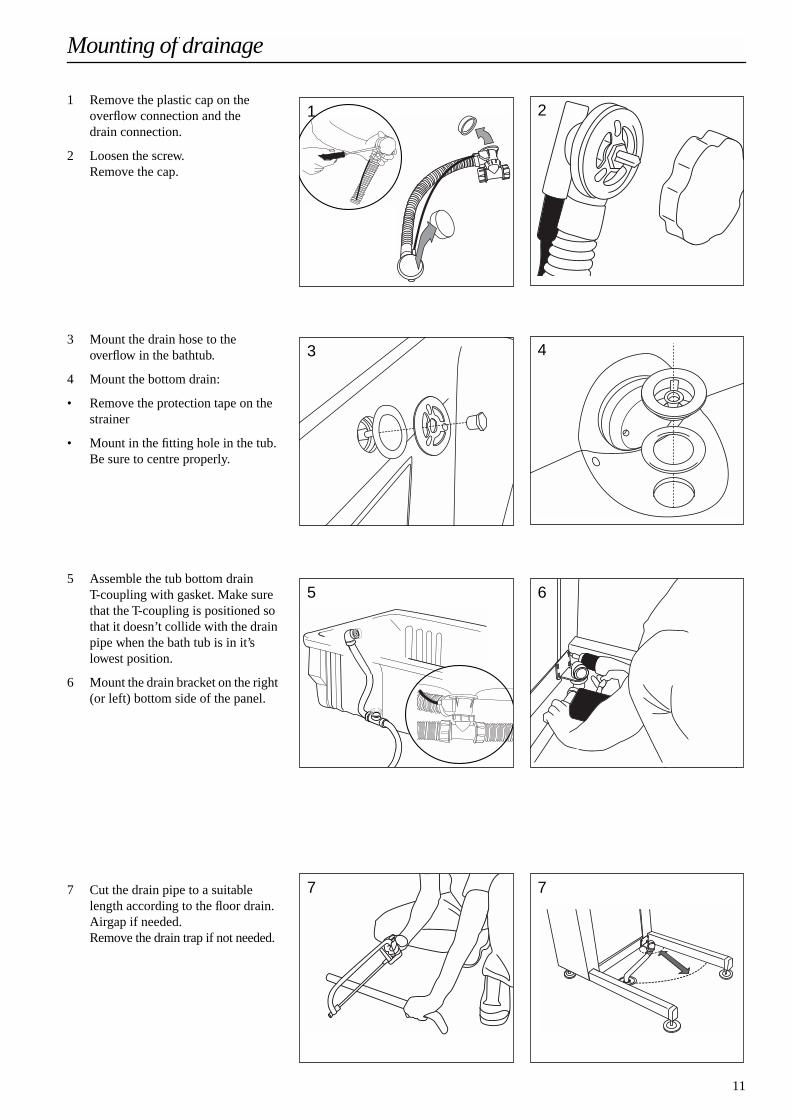
1 Remove the plastic cap on theoverflow connection and the drain connection.
2 Loosen the screw.
Remove the cap.
3 Mount the drain hose to the overflow in the bathtub.
4 Mount the bottom drain:
• Remove the protection tape on the strainer
• Mount in the fitting hole in the tub.Be sure to centre properly.
5 Assemble the tub bottom drainT-coupling with gasket. Make sure that the T-coupling is positioned so that it doesn’t collide with the drain pipe when the bath tub is in it’s lowest position.
6 Mount the drain bracket on the right (or left) bottom side of the panel.
7 Cut the drain pipe to a suitable length according to the floor drain.Airgap if needed.
Remove the drain trap if not needed.
Mounting of drainage
1 2
3 4
5 6
7 7
12
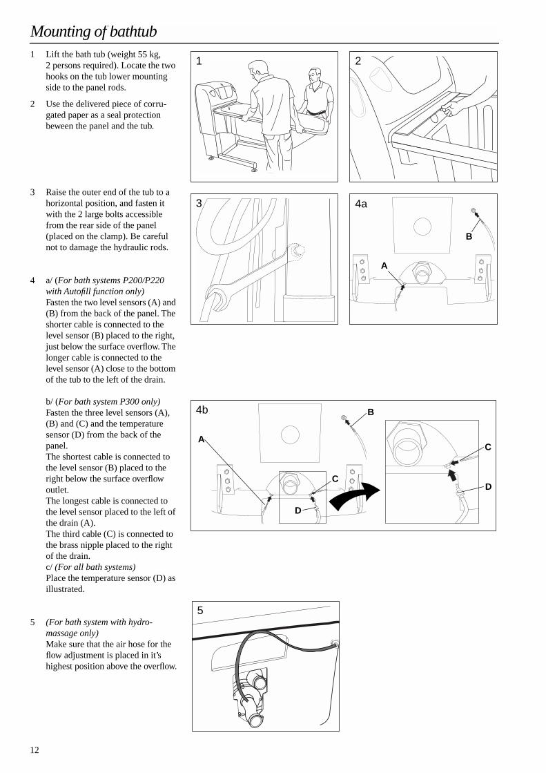
1 Lift the bath tub (weight 55 kg, 2 persons required). Locate the two hooks on the tub lower mounting side to the panel rods.
2 Use the delivered piece of corru-gated paper as a seal protection beween the panel and the tub.
3 Raise the outer end of the tub to a horizontal position, and fasten it with the 2 large bolts accessible from the rear side of the panel (placed on the clamp). Be careful not to damage the hydraulic rods.
4 a/ (
For bath systems P200/P220 with Autofill function only)
Fasten the two level sensors (A) and (B) from the back of the panel. The shorter cable is connected to the level sensor (B) placed to the right, just below the surface overflow. The longer cable is connected to the level sensor (A) close to the bottom of the tub to the left of the drain.
b/ (
For bath system P300 only)
Fasten the three level sensors (A), (B) and (C) and the temperature sensor (D) from the back of the panel.The shortest cable is connected to the level sensor (B) placed to the right below the surface overflow outlet.The longest cable is connected to the level sensor placed to the left of the drain (A).The third cable (C) is connected to the brass nipple placed to the right of the drain.c/
(For all bath systems)
Place the temperature sensor (D) as illustrated.
5
(For bath system with hydro-massage only)
Make sure that the air hose for the flow adjustment is placed in it’s highest position above the overflow.
Mounting of bathtub
1 2
3
B
A
4a
4b
A
B
C
DC
D
5

13
Earth ground continuity test for Bath System with hydrosound
Have a certified electrician perform earth ground continuity test between all locations indicated in the figure:
1 Earth bonding lug
2 All metal surfaces
3 Tub grounding stud
4 Transducer earth grounding stud
5 GND, yellow/green wire
• Do
not
use an audible tone type continuity tester for this test. The use of a digital type resistance meter capable of measuring anddisplaying resistance of 1
Ω
or less is suggested.
• A firm contact pressure on bothcontact points of the meter probes is necessary to measure resistance1
Ω
or less
All metal surfaces
5
4
1
3
2
Warning!A certified electrician must, following installa-tion, ensure that the earth ground continuity exists at locations marked in the figure. The resistance difference between all locations (1-5) shall be 0.2 Ω or less.Corrective action must be taken if resistance is above 0.2 Ω.

14
1 Mount the rear plate (4 screws)
2 Carry out water installation.
3 Calibrate the Bath System settings. P300: See separate document
Programming Instructions
.P200, P220: See DIP-switch adjustment on page 17.
4 Fasten the top box with two screws from the assembly kit.
5 Assemble the lid to the rear panel cover. Use the screws, washers and nuts (C) from the assembly kit.
6 Mount the rear panel cover together with the lid. Hang it on the two pin bolts, fasten the two domed nuts on the pin bolts and the 6 screws on the side of the panel.
7-9 For systems with integrateddispensing/disinfection only:
7 Place ArjoOil (ArjoSound), ArjoCare and ArjoClean bottles in the top box and attach the suction units to them. Connect as well.
A - ArjoClean (
Arjo DisinfectantCleanser)
B - ArjoCare(
Arjo Shampoo & Body Wash)
C -Arjo Oil or ArjoSound (
Arjo Skin Conditioner & Bath Oil)
8 Set the Disinfectant/Cleaner con-centration, see separate document
Operating and Daily Maintenance Instructions.
9 Fasten the securing lock plate (optional).
• Put one end in the fitting hole
• Push till it stops, fell the plate and fit the other end in the opposite side of the top box
• Turn the key for locking
10 Close the panel lid. Put the footrest in place. Fasten the pillow.
After mounting the bath tub
1 4
5 6
7AB
C
8
9a 9b
10
15
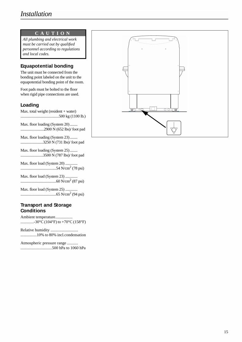
Equapotential bondingThe unit must be connected from thebonding point labeled on the unit to the equapotential bonding point of the room.
Foot pads must be bolted to the floor when rigid pipe connections are used.
LoadingMax. total weight (resident + water).........................................500 kg (1100 lb.)
Max. floor loading (System 20) .................................2900 N (652 lbs)/ foot pad
Max. floor loading (System 23) ................................3250 N (731 lbs)/ foot pad
Max. floor loading (System 25) ................................3500 N (787 lbs)/ foot pad
Max. floor load (System 20) ...................................................54 N/cm2 (78 psi)
Max. floor load (System 23) ...................................................60 N/cm2 (87 psi)
Max. floor load (System 25) ...................................................65 N/cm2 (94 psi)
Transport and Storage ConditionsAmbient temperature................. .............-30°C (104°F) to +70°C (158°F)
Relative humidity ...........................................10% to 80% incl.condensation
Atmospheric pressure range ..........................................500 hPa to 1060 hPa
Installation
All plumbing and electrical work must be carried out by qualified personnel according to regulations and local codes.
C A U T I O N

16
Electrical installation
• First check that the electrical supply corresponds with the information on the label on the backside of the panel.
• The unit must be permanently installed.
• The unit must be continuouslypowered and connected to separate fuse with ground fault circuit interrupter.
DIP Switches for AutofillThe P200 and P220 models are equipped with dip switches, which are located on the PCB and can be adjusted as in the tables below:
The unit shall be electrically connected with the following equipment (not included in delivery):
• Separate fuse.
• Ground fault circuit interrupter (10mA)
• Safety switch, according to regulations and local codes.
• Mains cable (3x16AWG / 3x1.5 mm2)
Model P200
PCB located in the power box on the lower backside of the panel.
* the amount of seconds of extended filling time from that the 0-level is fulfilled.
Connect the wires as described below:
• Neutral to the blue wire (N)
• Phase to the brown wire (L)
• Protective earth to the yellow/green wire (PE)
The unit must be permanently connected to the mains when used in USA and Canada.All electrical installations must comply with the US National Electrical Code andthe Canadian Electrical Code respectively.
Model P220
PCB located on the backside of the panel front.
*the amount of seconds of extended filling time from that the 0-level is fulfilled.
Model Market Voltage FrequencyFuse(slowblow)
Power consumption
StillbathEuropeNorth AmericaJapan
230/240V single phase AC120V single phase AC100V single phase AC
50Hz 60Hz 50/60Hz
6 A10 A12 A
max. 1200 VA
Hydrosound
EuropeNorth Americamodel 001E,Japan
230/240V single phase AC
120V single phase AC100V single phase AC
50Hz
60Hz 50/60Hz
6 A
10 A12 A
max. 1200 VA
HydromassageEuropeNorth AmericaJapan
230/240V single phase AC120V single phase AC100V single phase AC
50Hz 60Hz 50/60Hz
6 A10 A12 A
max. 1200 VA
P200
11
ONOFF
Japanese versionEU/North America version
22
ONOFF
Auto-fill activatedAuto-fill deactivated
34
OFFOFF
0 seconds*
34
ONOFF
60 seconds*
34
OFFON
120 seconds*
34
ONON
180 seconds*
MAIN SUPPLY
LN
21
A2A1
HYDROPUMP
14
6
13
RE2
5
43
F5
F4
F2F3
F1
P220
11
ONOFF
Japanese versionEU/North America version
22
ONOFF
Auto-fill activatedAuto-fill deactivated
34
OFFOFF
20 seconds*
34
ONOFF
60 seconds*
34
OFFON
120 seconds*
34
ONON
200 seconds*
17
Water installation
Max. static pressure:........................................6 bar (600 kPa, 87 psi)Min. operating pressure,Canada, Japan and USA:........................................1 bar (100 kPa, 15 psi)Recommended ...........>3 bar (300kPa, 45psi)
Min. operating pressure,All other markets:........................................2 bar (200 kPa, 29 psi)Recommended ...........>3 bar (300kPa, 45psi)
Min operating pressure CW, P100: ............................3bar (300 kPa, 45 psi)Recommended ...........>3 bar (300kPa, 45psi)
Min. flow/supply pipe: 25 l/min.(5.5 gal/min))(50 l/min CW+WW)(11gal/min CW+WW)
Cold water temperature: 2-25°C (36-77°F)
Warm water temperature:................................... 38-80°C (104-175°F)Recommended .................... >60°C (140°F)
The unit connections are G3/4" (BSP MALE or NP threads).
Calibration of the thermostat mixer
P100; P200; P220
When the installation is completed the thermostat mixer must be calibrated as follows:
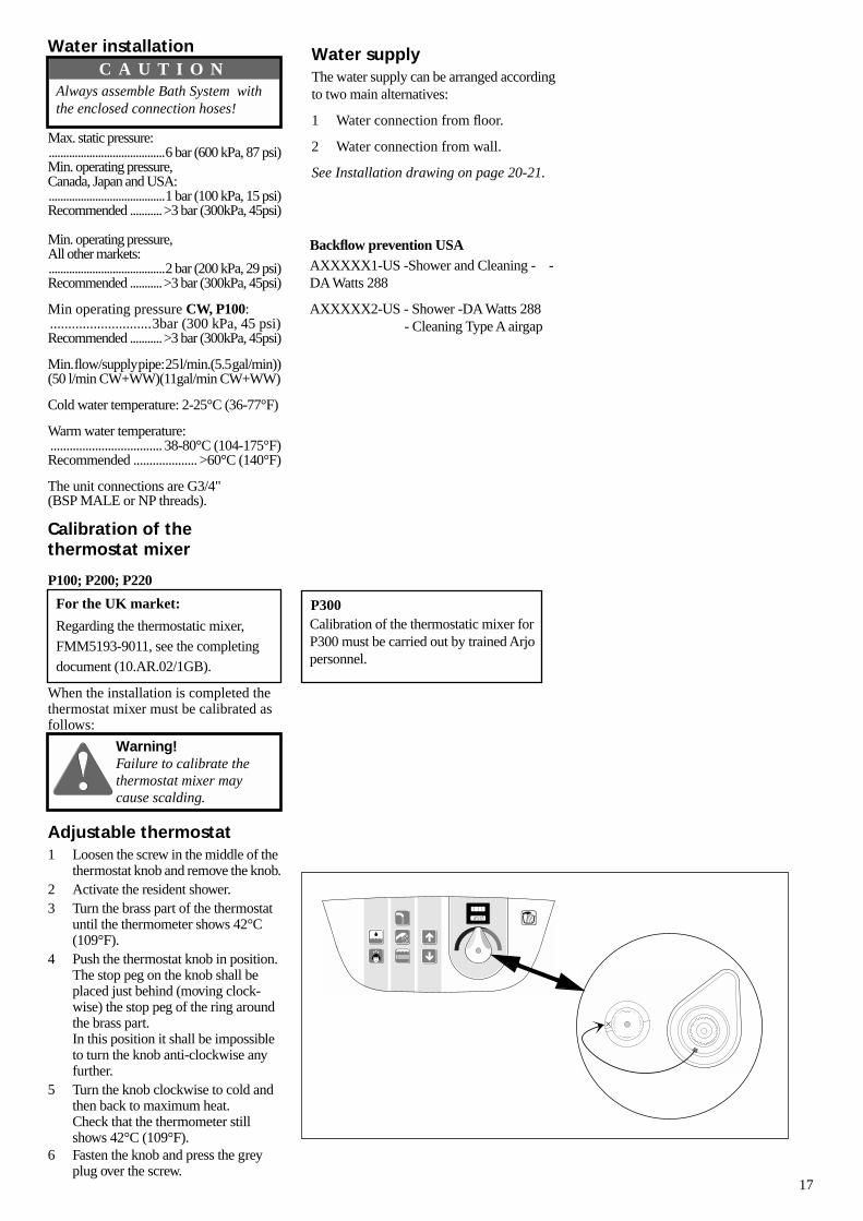
Adjustable thermostat1 Loosen the screw in the middle of the
thermostat knob and remove the knob.2 Activate the resident shower.3 Turn the brass part of the thermostat
until the thermometer shows 42°C (109°F).
4 Push the thermostat knob in position. The stop peg on the knob shall beplaced just behind (moving clock-wise) the stop peg of the ring around the brass part.In this position it shall be impossible to turn the knob anti-clockwise any further.
5 Turn the knob clockwise to cold and then back to maximum heat. Check that the thermometer still shows 42°C (109°F).
6 Fasten the knob and press the grey plug over the screw.
Water supplyThe water supply can be arranged according to two main alternatives:
1 Water connection from floor.
2 Water connection from wall.
See Installation drawing on page 20-21.
Always assemble Bath System with the enclosed connection hoses!
C A U T I O N
Backflow prevention USAAXXXXX1-US -Shower and Cleaning - -DA Watts 288
AXXXXX2-US - Shower -DA Watts 288- Cleaning Type A airgap
For the UK market:
Regarding the thermostatic mixer,FMM5193-9011, see the completing document (10.AR.02/1GB).
Calibration of the thermostatic mixer for P300 must be carried out by trained Arjo personnel.
P300
Warning!Failure to calibrate the thermostat mixer may cause scalding.
18
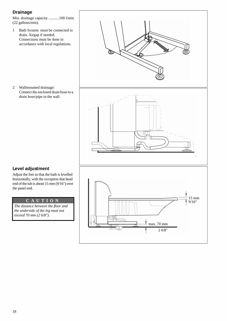
DrainageMin. drainage capacity ...........100 l/min(22 gallons/min).
1 Bath System must be connected to drain. Airgap if needed.Connections must be done in accordance with local regulations.
2 Wallmounted drainage:Connect the enclosed drain hose to a drain hose/pipe in the wall.
Level adjustmentAdjust the feet so that the bath is levelled horizontally, with the exception that head end of the tub is about 15 mm (9/16") over the panel end.
15 mm
max. 70 mm
9/16"
2 6/8"
The distance between the floor and the underside of the leg must not exceed 70 mm (2 6/8").
C A U T I O N

19
Space Requirements
Measurements, Volume and WeightRhapsody System 20 System 23 System 25Tub length 1600 mm (63”) 1900 mm (75”) 2150 mm (85”)
Tub + panel, length 1970 mm (77 5/8”) 2270 mm (89 3/8”) 2520 mm (99 1/4”)
Tub width 970 mm (38”) 970 mm (38”) 970 mm (38”)
Total weight 390 kg (860 lbs) 470 kg (1037 lbs) 525 kg (1158 lbs)
Water consumption (filled, with resident) 185 l (49 gallons) 260 l (68.5 gallons) 310 l (82 gallons)
Filling time at 300 kPa dynamic pressure (WW 45ºC)(45 psi dynamic pressure (WW 113ºF)
3 minutes 30 sec 5 minutes 6 minutes
Emptying time, tub in highest position (filled, with resident) 3 minutes 4 min 30 sec 5 min 15 sec
Primo System 20 System 23
Tub length 1600 mm (63”) 1900 mm (75”)
Tub + panel, length 1970 mm (77 5/8”) 2270 mm (89 3/8”)
Tub width 760 mm (30") 760 mm (30")
Total weight 380 kg (838 lbs) 460 kg (1014 lbs)
Water consumption (filled, with resident) 180 l (47.5 gallons) 250 l (66 gallons)
Filling time at 300 kPa dynamic pressure (WW 45ºC)(45 psi dynamic pressure WW 113ºF)
3 min 30 sec 5 min
Emptying time, tub in highest position (filled, with resident) 3 minutes 4min 30 sec
P100 P200, P220, P300 Fixed height
Tub rim, lowest position 690 mm (27") 620mm (24") 835 ( 32 7/8")
Tub rim, highest position 1120 mm (44") 1120 mm (44") 835 ( 32 7/8")
Stroke range 430mm (17") 500 mm (20")
Lifting capacity (filled + resident) 500 kg (1100 lbs) 500 kg (1100 lbs)
Raising time (full load) approx 30 sec 30 sec
Lowering time (full load) approx 30 sec 30 sec
Airborn noise (DIN45635-19-01-KL2) max 70 dB(A) 70 dB(A)
Technical specifications
Rhapsody System 20/23/25
1100 mm / 44" 800 mm / 32"300 mm / 12"
2750 mm / 108"
800
mm
/ 3
2"
150
mm
/ 6
"
3195
mm
/ 1
27"
300 mm 12"
300 mm / 12"
2895
mm
/ 1
15"
3445
mm
/ 1
36"
Primo System 20/23
1100 mm / 44" 800 mm / 32"300 mm / 12"
2750 mm / 108"80
0 m
m /
32"
2895
mm
/ 1
15"
150
mm
/ 6
"300 mm
12"
300 mm / 12"
3195
mm
/ 1
27"

20
97038"
82032 1/4"
70027 4/8"
5 7/8"
2 "
9 7/8" 39"/ 40 4/8"/ 49 5/8"
18 1/8"
2 6/8"
2"
60 2 3/8"
175 6 7/8" 760
30"
For other solutionsconcerning drainage andwater inlet, please contactArjo.
150
70
460
990/ 1030/ 1260250
125 4 7/8"
77 5/8" / 89 3/8" / 99 1/4"
50
50
600(±100) 23 5/8"(± 4")
1970/ 2270/ 2520
Equapotential bonding
120V, 60HzMains supply 230V, 50Hz
5 7/8"
3 1/8"
10 5/8"22"
15 6/8"
80
3 1/8"
80
r=560270
400150
Possible area for location of floor drain
CWHW
Wallmounted drainage
See drain illustr. below
62 3/8"
44 1/8"
Min. 1155/45 4/8" (P100)Fixed height 1300 /51 1/8")
Fixed height 835 /32 7/8")
Min. 1085/ 42 6/8"(P200, 220, 300)Max. 1585/
Min. 690/ 27 1/8" (P100)Min. 620/ 24 3 /8" (P200, 220, 300)Max. 1120/
CW*
CW* = only P100,Japan market
Overall dimensions - Rhapsody bathtub

21
70027 4/8"
5 7/8"
5 7/8"
62 3/8"
44 1/8"
3 1/8"
2 "
10 5/8"22"
15 6/8"
9 7/8" 39"/ 40 4/8"
18 1/8"
2 6/8"
76030"
For other solutionsconcerning drainage andwater inlet, please contactArjo.
150
Min. 1155/45 4/8" (P100)Fixed height 1300 /51 1/8")
Fixed height 835 /32 7/8")
Min. 1085/ 42 6/8"(P200, 220, 300)Max. 1585/
Min. 690/ 27 1/8" (P100)Min. 620/ 24 3 /8" (P200, 220, 300)Max. 1120/
70
460
80
3 1/8"
80
See drain illustr. below
990/ 1030
r=560
250
77 5/8" / 89 3/8"
50
600(± 100) 23 5/8"(± 4")
270
400150
Possible area for location of floor drainWallmounted drainage
1970/ 2270
Equapotential bonding
120V, 60HzMains supply 230V, 50Hz
2"50
82032 1/4" CW
HW
CW*
CW* = only P100,Japan market
60 2 3/8"
175 6 7/8"
125 4 7/8"
Overall dimensions - Primo bathtub

AUSTRALIA
Arjo Hospital Equipment Pty Ltd154 Lytton RoadBULIMBABrisbane QLD 4171AustralienTel.nr. 07-3395 6311Faxnr. 07-3395 6712
AUSTRIA
Arjo-Sic GmbHFöhrenweg 56065 THAURTel.nr. 05223- 49 33 50Faxnr. 05223 -49 33 50 - 75
BELGIUM
Arjo Hospital Equipment nv/saTwaalf Apostelenstraat 149051 SINT-DENIJS-WESTREMTel. 09-242 86 42Fax 09-242 86 43E-Mail: [email protected]
CANADA
Arjo Canada Inc.1575 South Gateway RoadUnit "C"MISSISSAUGA, ON, L4W 5JITel: 1-800-665-4831Fax: 1-800-309-1116E-mail: [email protected] page: www.arjo.ca
CZECH REPUBLIC
Arjo Hospital Equipment s.r.o.Strmà 35616 00 BRNOTel. 05 754 252Telefax 05 412 13550
DENMARK
Getinge-Arjo A/SFirskovvej 232800 LyngbyTel. 45 93 27 27Telefax 45 93 41 20
FAR EASTArjo Far East Limited1001-03 APEC Plaza49 Hoi Yuen Road, Kwun Tong, KowloonHONG KONGTel. 2508 9553Telefax 2508 1416
FINLAND
OY Vestek ABMartinkuja 402270 ESPOOTel. 9 8870120Telefax 9 88701291
FRANCE
Arjo Equipements Hospitaliers S.A.Central Parc, 4 Allée du Sanglier93421 VILLEPINTE CEDEXTel. 01 49 63 47 00Telefax 01 48 61 41 42
GERMANY
Arjo Systeme für Rehabilitation GmbHRudolf Diesel-Strasse 565719 HOFHEIMTel. 06122 - 80 40Telefax 06122 - 804 160
GREECE
C. Psimitis Co Ltd59, Dimitrion Str.16121 KAISARIANITel. 1 724 36 68Telefax 1 721 55 53
ITALY
Arjo Italia S.p.A.Via Della Marcigliana, 53200139 ROMATel. 06-87 127 023Telefax 06-87 120 640
THE NETHERLANDS
Arjo Nederland B.V.De Blomboogerd 84003 BX TIELPostbus 61164000 HC TIELTel: 0344 - 640 800Fax: 0344 - 640 885
NORWAY
Getinge-Arjo ASOle Deviks vei 4, 4. etasje0666 OSLOTel. 23 05 11 80Telefax 23 05 11 98
POLAND
Arjo Poland Ltd.Ul.Walecznych 4403-916 WARSZAWATel. 22 616 2916Telefax 22 617 7689
PORTUGAL
RTL Edificio d’ASR. Moreiró, 65 Gandra4580 PAREDESTel. 224 119 070Telefax 224 119 079
SPAIN
Arjo Spain, S.AVallespir, 1308970 SANT JOAN DESPI - BARCELONA Tel. 3- 477 37 33Telefax 3- 477 37 32
SWEDEN
Arjo Sverige ABVerkstadsvägen 5Box 61241 21 ESLÖVTel. 0413-645 00Telefax 0413-138 76
SWITZERLAND
Arjo-SIC AGWartenbergstrasse 15Postfach4020 BASELTel. 061-317 97 97Telefax 061-311 97 42
UNITED KINGDOM
Arjo LtdSt Catherine StreetGLOUCESTER GL1 2SLTel. 08702 430 430Telefax 01452 - 525 207
USA
Arjo Inc.50 North Gary AvenueROSELLE, IL 60172Tel. 1-800-323-1245Telefax 1-888-594-2756www.arjousa.com
If your country is not listed here, please contact your local distributor or: Arjo International AB, Box 61, S-241 21 ESLÖV, Sweden, Tel. +46 413 645 00, Telefax +46 413 55 55 86
Subject to alterations - Rätt till ändringar förbehålles - Recht auf technische Änderungen vorbehalten - Sujet à modification


