T1 6 *9008142* www.tennantco.com Rider Scrubber Operator Manual 9008142 Rev. 02 (12-2011) North America / International The Safe Scrubbing Alternative R Hygenic Fully Cleanable Tanks ES Extended Scrub System R R (Battery)
Transcript
T16
*9008142*www.tennantco.com
Rider ScrubberOperator Manual
9008142Rev. 02 (12-2011)
North America / International
The Safe Scrubbing Alternative �
Hygenic Fully Cleanable TanksES Extended Scrub System
�
�
(Battery)
This manual is furnished with each new model. It provides necessary operation and maintenance instructions.
Read this manual completely and understand the machine before operating or servicing it.
This machine will provide excellent service. However, the best results will be obtained at minimum costs if:
� The machine is operated with reasonable care.
� The machine is maintained regularly - per the machine maintenance instructions provided.
� The machine is maintained with manufacturer supplied or equivalent parts.
PROTECT THE ENVIRONMENTPlease dispose of packaging materials,old machine components such asbatteries, hazardous fluids includingantifreeze and oil, in anenvironmentally safe way according tolocal waste disposal regulations.
Always remember to recycle.
MACHINE DATA
Please fill out at time of installation for future reference.
Touch−N−Go, 1−STEP, Grip−N−Go, Dura−Track, Positive Drain Control, SmartRelease, Duramer, FaST−PAK, are US registered and unregisteredtrademarks of Tennant Company.
Specifications and parts are subject to change without notice.
Original Instructions, copyright � 2011 TENNANT Company, Printed in U.S.A.
The following precautions are used throughoutthis manual as indicated in their description:
WARNING: To warn of hazards orunsafe practices that could result insevere personal injury or death.
FOR SAFETY: To identify actions that must befollowed for safe operation of equipment.
This machine is designed solely for scrubbing dirtand dust in a well lit indoor environment. Tennantdoes not recommend using this machine in anyother environment.
The following information signals potentiallydangerous conditions to the operator orequipment. Read this manual carefully. Knowwhen these conditions can exist. Locate all safetydevices on the machine. Then, take necessarysteps to train machine operators. Report machinedamage or faulty operation immediately. Do notuse the machine if it is not in proper operatingcondition.
WARNING: Batteries emit hydrogen gas.Explosion or fire can result. Keepsparks and open flame away. Keepcovers open when charging.
WARNING: Flammable materials cancause an explosion or fire. Do not useflammable materials in tank(s).
WARNING: Flammable materials orreactive metals can cause an explosionor fire. Do not pick up.
FOR SAFETY:
1. Do not operate machine:− Unless trained and authorized.− Unless operation manual is read and
understood.− Unless mentally and physically
capable of following machineinstructions.
− With brake disabled.− If it is not in proper operating
condition.− In flammable or explosive areas.− In areas with possible falling objects
unless equipped with overhead guard.
2. Before starting machine:− Make sure all safety devices are in
place and operate properly.− Check brakes and steering for proper
operation.− Adjust seat and fasten seat belt (if so
equipped).
3. When using machine:− Do not pick up burning or smoking
debris, such as cigarettes, matches orhot ashes
− Go slowly on inclines and slipperysurfaces.
− Use care when backing machine.− Do not carry passengers on machine.− Follow mixing and handling
instructions on chemical containers.− Report machine damage or faulty
operation immediately.
4. Before leaving or servicing machine:− Stop on level surface.− Turn off machine and remove key.
5. When servicing machine:− Avoid moving parts. Do not wear loose
clothing or jewelry when working onmachine.
− Block machine tires before jackingmachine up.
− Jack machine up at designatedlocations only. Block machine up withjack stands.
− Use hoist or jack that will support theweight of the machine.
− Wear eye and ear protection whenusing pressurized air or water.
− Disconnect battery connections beforeworking on machine.
− Wear protective gloves and eyeprotection when handling vinegar.
− Avoid contact with battery acid.− Use Tennant supplied or equivalent
replacement parts.
6. When loading/unloading machineonto/off truck or trailer.− Turn off machine.− Use truck or trailer that will support
the weight of the machine.− Use winch. Do not push the machine
onto/off the truck or trailer unless theload height is 380 mm (15 in) or lessfrom the ground.
− Block machine tires.− Tie machine down to truck or trailer.
SAFETY PRECAUTIONS
T16 9008142 (1−11)4
The safety labels appear on the machine in thelocations indicated. Replace damaged labels.
BATTERY CHARGINGLABEL − LOCATEDON SEAT PANEL.
FLAMMABLE SPILLSLABEL − LOCATED ONUNDERSIDE OFSOLUTION TANK COVER.
FOR SAFETY LABEL −LOCATED ON CIRCUITBREAKER PANEL.
FLAMMABLE MATERIALSLABEL − LOCATED ONUNDERSIDE OFRECOVERY TANK COVERAND ON CIRCUITBREAKER PANEL.
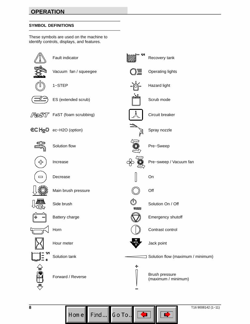
OPERATION
5T16 9008142 (3−11)
OPERATION
MACHINE COMPONENTS
I H
BC
G
A
D
F
K
E
J
L
M
N
O
356071
A. Recovery tankB. Recovery tank coverC. Backup alarm / flashing light (option)D. Solution tank coverE. Solution tankF. Rear squeegeeG. Side squeegeeH. Scrub headI. Battery compartment
J. Pre−Sweep assembly (option)K. Pre−Sweep side brushes (option)L. Pre−Sweep debris hopper (option)M. Side brush (option)N. Operator seatO. FaST PAK (option)
ec−H20 System Module (option)FaST solution system (option)
The battery discharge indicator displays thecharge level of the batteries while the machine isoperating.
When the batteries are fully charged, all five barsare lit. Recharge the batteries when there are nolonger any bars shown in the display.
NOTE: The reading on the battery dischargeindicator is not accurate when the machine is firstpowered on. Operate the machine a few minutesbefore reading the charge level of the batteries.
NOTE: The battery discharge indicator will notreset from the flashing indicator (lowest bar on theindicator) unless the batteries have been fullycharged.
HOUR METER
The Hour meter records the hours the machinewas operated. Use this information to determinemachine service intervals.
RECOVERY TANK INDICATOR
The recovery tank indicator displays the amountof liquid in the recovery tank. All scrubbingfunctions will stop when the recovery tank is full.Empty the recovery tank when the indicatorreaches 100%.
SOLUTION TANK INDICATOR
The solution tank indicator displays the amount ofliquid in the solution tank. Refill the solution tankwhen there are no longer any bars shown in thedisplay. The machine will stop scrubbing when thesolution tank is empty.
OPERATION
10 T16 9008142 (1−11)
POWER KILL SWITCH
The power kill switch immediately stops all powerto the machine.
Stop machine power: Press the power kill switch.
Restart machine power: Turn the power kill switchto the right to release the switch. Turn the keyswitch off, then turn the key fully clockwise andrelease it to the On position.
OPERATING / HAZARD LIGHT SWITCH(OPTION)
Operating and Hazard Lights On: Press the top ofthe Operating / hazard light switch.
Operating Lights On: Press the Operating /hazard light switch to the middle position.
All Lights Off: Press the bottom of the Operating /hazard light switch.
SEAT SUPPORT ARM
The seat support arm holds the seat up to allowaccess to the batteries and circuit breakers.
To engage the seat support arm, lift the seatcompletely open and insert the seat support arminto the hole in the operator seat plate.
OPERATION
11T16 9008142 (1−11)
OPERATOR SEAT
The front−to−back adjustment lever adjusts theseat position.
DELUXE SUSPENSION SEAT (OPTION)
The operator seat has four adjustments: backrestangle, operator weight, lumbar, and front to back.
Use caution when tilting the deluxe seat. Thedeluxe seat is heavier than the standard seat.
The backrest adjustment knob adjusts the angleof the backrest.
The weight adjustment knob controls the firmnessof the operator seat. Use the gauge next to theweight adjustment knob to help determine seatfirmness.
The lumbar knob adjusts the lower backrestportion of the seat.
The front−to−back adjustment lever adjusts theseat position.
SEAT BELTS
FOR SAFETY: Before starting machine, adjustseat and fasten seat belt.
OPERATION
12 T16 9008142 (1−11)
CONTRAST CONTROL BUTTON
Use the Contrast control button to darken / lightenthe LCD display.
CONFIGURATION MODE BUTTON
The Configuration mode button is for accessingthe configuration and diagnostic modes. Onlyproperly trained service personnel and TENNANTrepresentatives should access these modes.
PROPEL PEDAL
Press the Propel pedal to move the machine.
BRAKE PEDAL
Press the Brake pedal to stop the machine.
DIRECTIONAL SWITCH
Use the Directional switch to select either theforward or reverse direction. Press the propelpedal to move the machine.
NOTE: An audible alarm will sound when theDirectional switch is placed into reverse.
NOTE: Machines equipped with the optionalflashing light / backup alarm only: The optionalbackup light and alarm will function only when themachine is moving in reverse.
OPERATION
13T16 9008142 (1−11)
VACUUM FAN / SQUEEGEE BUTTON
Lower squeegee and turn vacuum fan on: Pressthe Vacuum fan / squeegee button. The indicatorlight will illuminate when the squeegee is lowered.
Raise squeegee and turn vacuum fan off: Pressthe Vacuum fan / squeegee button. The indicatorlight will go out when the squeegee is raised.
NOTE: The 1−STEP button does not need to beactivated to operate the vacuum fan / squeegeesystem. The vacuum fan / squeegee button canbe turned on or turned off with the 1−STEP buttoneither on or off.
SOLUTION ON / OFF BUTTONS
Shut off the solution flow: Press the Solution on /off button to shut off the solution flow. All thesolution flow indicator lights will turn off.
Turn on the solution flow: Press the Solution on /off button to turn on the solution flow. The solutionindicator lights will turn back on and the solutionflow will default to the last setting used.
OPERATION
14 T16 9008142 (1−11)
HOW THE MACHINE WORKS
The 1−STEP button makes it possible toimmediately begin scrubbing by operating all thescrubbing functions.
When in the conventional Scrub mode, a waterand detergent mixture is used to scrub the floor.
When in the optional ES (Extended Scrub) mode,the dirty solution in the recovery tank is filteredthrough the ES system and returned to thesolution tank for reuse. Detergent is then injectedinto the returned solution to revitalize the cleaningcapability of the solution.
When in the optional FaST (Foam scrubbing)mode, the FaST scrubbing system mixes theFaST−PAK concentrate with a small amount ofwater, creating a large volume of expanded wetfoam. The FaST system can be used with allscrubbing applications.
When in the optional ec−H2O (electricallyconverted water) mode, normal water passesthrough a module where it is oxygenated andcharged with an electric current. The electricallyconverted water changes into a blended acidicand alkaline solution forming a neutral pH cleaner.The converted water attacks the dirt, breaks it intosmaller particles, and pulls it off the floor surfaceallowing the machine to easily scrub away thesuspended soil. The converted water then returnsto normal water in the recovery tank. The ec−H2Osystem can be used with all double scrubbing andheavy duty scrubbing applications.
BRUSH AND PAD INFORMATION
For best results, use the appropriate brush or padfor the cleaning application. Listed below arebrushes and pads and the applications for whicheach is best suited.
NOTE: The amount and type of soilage play animportant role in determining the type of brush orpad to use. Contact a Tennant representative forspecific recommendations.
Polyester brush (Cylindrical) − Softer generalpurpose polyester bristles gently clean whilescrubbing. Perfect for sensitive floor surfaces.Polyester does not absorb water so it is preferredover Nylon in wet applications.
PolyPro brush (Cylindrical) − Heavy dutypolypropylene bristles provide a more aggressivecleaning performance and can more easily liftcompacted dirt, debris, and sand while offeringexcellent scrubbing performance.
Polypropylene brush (Cylindrical and Disk)* −General purpose polypropylene bristles lift lightlycompacted dirt without scuffing high-gloss coatedfloors.
Super AB brush (Cylindrical and Disk)* −Nylon fiber with an abrasive grit to remove stainsand compacted dirt. Aggressive action on anysurface. Performs well on buildup, grease, or tiremarks.
* This brush is also available for the side brush.
Stripping pad (Brown)− Quickly and easily cutsthrough old finish to prepare the floor forrecoating.
Scrubbing pad (Blue) − Removes dirt, spills, andscuffs. Leaves a clean surface ready forrecoating.
Buffing pad (Red) − Quickly cleans and removesscuff marks while polishing the floor to a highgloss.
Polishing pad (White) − Maintains a high gloss.Use for buffing very soft finishes and lower trafficareas, and polishing soft waxes on wood floors.
OPERATION
15T16 9008142 (1−11)
High productivity pad (Black) − Aggressivelystrips floor finishes/sealers. Use for veryheavy−duty scrubbing. This pad can only be usedwith the grip pad driver, not the tufted pad driver.
Surface preparation pad (Maroon) −Aggressively strips floors without use ofchemicals.
Grip pad driver − The grip−face backing allowspads to be fully used and holds pads in placewithout penetrating the pad. The spring−activatedcentering device works with all Tennant pads andallows for fast, easy pad replacement.
Tufted pad driver − Standard pad driver hasshort bristles, or “tufts,” on the back to hold thepad in place. This driver works with all Tennantpads except the black high productivity pad.
WHILE OPERATING THE MACHINE
Pick up oversized debris before scrubbing. Pickup wire, string, twine, large pieces of wood, or anyother debris that could become wrapped aroundor tangled in the brushes.
Drive in a straight a path as possible. Avoidbumping into posts or scraping the sides of themachine. Overlap the scrub paths by severalcentimeters (a few inches).
Avoid turning the steering wheel too sharply whenthe machine is in motion. The machine is veryresponsive to the movement of the steering wheel.Avoid sudden turns, except in emergencies.
Adjust the machine speed, brush pressure, andsolution flow as required when scrubbing. Use thelowest brush pressure and solution flow settingsfor best performance.
If poor cleaning performance is observed, stopcleaning and refer to MACHINETROUBLESHOOTING in this manual.
Perform the Daily Maintenance Procedures aftereach use (see MACHINE MAINTENANCE in thismanual).
Drive the machine slowly on inclines. Use thebrake pedal to control machine speed ondescending inclines. Scrub with the machine upinclines rather than down inclines.
FOR SAFETY: When using machine, go slowlyon inclines and slippery surfaces.
The maximum rated incline for scrubbing with themachine is 4� or 7%. The maximum rated inclineduring transport of the machine is 8� or 14%.
OPERATION
16 T16 9008142 (3−11)
PRE−OPERATION CHECKLIST
Perform the following steps before operating themachine:
� Check the operating lights.
� Check left side squeegee for wear anddamage.
� Check main brushes for wear and damage.Remove wire, string, or twine wrapped aroundthe main scrub brushes.
� Machines equipped with cylindrical brushes:Confirm the debris tray is empty and clean.
� Machines equipped with side brush option:Check for wire, string, or twine wrappedaround the scrub brush.
� Machines equipped with side brush option:Check squeegee for wear and damage.
� Machines equipped with Pre−Sweep option:Check for wire, string, or twine wrappedaround the scrub brush.
� Machines equipped with Pre−Sweep option:Check dust control filter bag.
� Machines equipped with Pre−Sweep option:Confirm debris trough is empty.
� Check the rear squeegees for wear anddamage.
� Check the recovery and solution tank coverseals for wear or damage.
� Confirm the vacuum fan inlet filter is clean.
� Check the right side squeegee for wear anddamage.
� Machines equipped with ES option: EnsureES filter at bottom of recovery tank is clean.
� FaST Scrubbing: Check the FaST PAKconcentrate agent level, replace carton asneeded. See the INSTALLING THE FaSTPAK AGENT section of the manual.
� For FaST or ec−H2O Scrubbing: Confirm allconventional cleaning agents/restorers aredrained and rinsed from the solution tank.
� For FaST or ec−H2O Scrubbing: Confirm thesolution tank is filled with clear cool wateronly.
� Check the brakes and steering for properoperation.
� Check the tires for damage.
� Check maintenance records to determinemaintenance requirements.
OPERATION
17T16 9008142 (1−11)
STARTING THE MACHINE
FOR SAFETY: Before starting machine, adjustseat and fasten seat belt.
1. Sit in the operators seat.
2. Turn the key switch completely past the onposition and release the key switch. The keyswitch will automatically return to the onposition.
3. Place the directional switch into the directionneeded to travel.
4. Press the propel pedal to move the machine.
NOTE: The machine will not travel unless theoperator is sitting in the operator seat.
FOR SAFETY: Before leaving or servicingmachine, stop on level surface and turn offmachine.
1. Open the solution tank cover.
2. Fill the solution tank with only clean COOLWATER (less than 21°C / 70°F). DO NOT usehot water or add any conventional floorcleaning detergents or a FaST or ec−H2Osystem failure may result. Fill the solutiontank with water until the level is approximately50 mm (2 in) below the indicator tab.
WARNING: Flammable materials cancause an explosion or fire. Do not useflammable materials in tank(s).
NOTE: Do not use the FaST or ec−H2O systemwhen there are conventional cleaning detergentsin the solution tank. Drain, rinse, and refill thesolution tank with clear cool water beforeoperating the FaST or ec−H2O system.Conventional cleaning detergents may cause aFaST or ec−H2O system failure.
3. Close the solution tank cover.
OPERATION
18 T16 9008142 (1−11)
CONVENTIONAL SCRUBBING MODE
FOR SAFETY: Before leaving or servicingmachine, stop on level surface and turn offmachine.
1. Open the solution tank cover.
2. Partially fill solution tank with water (not toexceed 60°C / 140°F). Pour the requiredamount of detergent into the solution tank.Continue filling the solution tank with wateruntil the level is approximately 50 mm (2 in)below the indicator tab.
WARNING: Flammable materials cancause an explosion or fire. Do not useflammable materials in tank(s).
ATTENTION: For Conventional Scrubbing,only use recommended cleaning detergents.Machine damage due to improper detergentusage will void the manufacturer’s warranty.
NOTE: Pour a recommended foam controlsolution into the recovery tank if excessive foamappears. For specific detergentrecommendations, contact a Tennantrepresentative.
3. Close the solution tank cover.
OPERATION
19T16 9008142 (1−11)
ES (EXTENDED SCRUB) MODE
FOR SAFETY: Before leaving or servicingmachine, stop on level surface and turn offmachine.
1. Open the solution tank cover.
2. Fill solution tank with water (not to exceed60°C / 140°F). Fill the solution tank with wateruntil the level is approximately 50 mm (2 in)below the indicator tab.
3. Fill the recovery tank with water (not toexceed 60°C / 140°F). Fill the recovery tankto just above the top of the ES filter.
4. Fill the ES detergent tank with detergent.
WARNING: Flammable materials cancause an explosion or fire. Do not useflammable materials in tank(s).
5. Close the solution tank cover.
OPERATION
20 T16 9008142 (1−11)
SETTING SCRUB MODES
The Scrub mode button enables the scrubbingfunctions to come on when the 1−STEP button isactivated. The light and cleaning system logo nextto the button will come on. The machine willdefault to the last setting used when it is poweredon or off.
NOTE: When the ES system is turned on there isa slight delay before the ES pump beginsoperating.
SETTING BRUSH PRESSURE
Under normal cleaning conditions, the brushpressure should be set to the lowest setting (thebottom light). Under heavy grime conditions, thebrush pressure can be set to a higher setting (thetop two lights). Travel speed and floor conditionswill affect cleaning performance.
With the 1−STEP button activated, press theBrush pressure button to set the brush pressure.Use the Brush pressure button to both raise orlower the brush pressure settings. If brushes areworn, it may be necessary to increase the brushpressure. The machine will default to the lastsetting used when it is powered on or off.
SETTING SOLUTION FLOW
With the 1−STEP button activated, press eitherSolution increase button (+) or Solution decreasebutton (−) to set the solution flow level. Travelspeed and floor conditions will affect scrubbingperformance. The machine will default to the lastsetting used when the machine is powered on oroff. The solution flow indicator lights display thecurrent solution flow setting.
NOTE: When using the FaST or ec−H2O system(option), the solution flow increase and solutionflow decrease buttons are nonfunctional. TheFaST and ec−H2O system flow rates are pre−set.All three solution flow indicator lights will be lit ifthe machine is in the ec−H2O or FaST mode.
CONVENTIONAL SOLUTION FLOW
Under normal soilage conditions the solution flowlevel should be set to the lowest setting (the leftlight). Under heavy grime conditions, the solutionflow level should be set to the higher settings(middle or right lights).
ES (EXTENDED SCRUB) SOLUTION FLOW
For ES machines, the detergent flow is turnedoff when the solution flow is in the lowestsetting (one light). The middle setting (twolights) and highest setting (three lights) allowsolution AND detergent flow. The lowest setting(one light) allows solution flow WITHOUT addingdetergent. Detergent does not have to becontinuously added with the solution flow to attaineffective scrubbing results. Under normal soilageconditions, the solution flow level should bealternated between the middle and lowest setting.
OPERATION
21T16 9008142 (1−11)
SCRUBBING
FOR SAFETY: Do not operate machine, unlessoperator manual is read and understood.
1. Start the machine.
2. Press the 1−STEP button. The light near thebutton will come on. All the preset scrubbingfunctions will turn on.
3. Press the scrub mode button to select thescrub mode (ec−H2O, FaST, or ES). Theindicator light and mode logo will illuminate.
4. If necessary, adjust the brush pressure andsolution flow.
5. Place the directional switch in the directionthe machine is to be moved (forward orreverse).
6. Press the propel pedal to begin scrubbing.
NOTE: DO NOT turn on the FaST or ec−H2Osystem during conventional scrubbing.Conventional cleaning detergents could cause aFaST or ec−H2O system failure. Drain, rinse, andrefill the solution tank with cool clean water beforeoperating the FaST or ec−H2O system.
WARNING: Flammable materials orreactive metals can cause an explosionor fire. Do not pick up.
FOR SAFETY: When using machine, go slowlyon inclines and slippery surfaces.
NOTE: The squeegee automatically rises whenthe machine is driven in reverse. This preventsdamage to the squeegee.
ec−H2O Model: If an alarm sounds and thewarning / fault indicator indicator light flashes theec−H2O module must be flushed to resumeec−H2O operation (See ec−H2O MODULEFLUSH PROCEDURE).
NOTE: When the alarm sounds press the scrubmode button to shut off the ec−H2O system andcontinue scrubbing or flush the ec−H2O system.
ec−H2O SYSTEMINDICATOR LIGHTCODE
CONDITION
Solid blue indicatorlight
Normal operation
Flashing red warning/ fault indicator light
Flush ec−H2O module
Solid red warning /fault indicator light
Contact Service Center
7. Release the directional pedal and press thebrake pedal to stop the machine.
8. Press the 1−STEP button to stop scrubbing.The light near the button will go off andscrubbing functions will stop after a shortdelay.
OPERATION
22 T16 9008142 (1−11)
DOUBLE SCRUBBING
Use the double scrubbing method to clean heavilysoiled areas.
Double scrubbing can be performed using theFaST SCRUBBING SYSTEM (option), ec−H2OSCRUBBING SYSTEM (option) orCONVENTIONAL SCRUBBING methods.
Pre−sweep and side brush (option) machines:Leave the Pre−sweep and side brush (options) inthe raised position while double scrubbing.
To raise the side squeegees for double scrubbing,remove the clevis pins from the storage locations.Manually raise both side squeegee assemblies,then reinsert the pins into the holes in the sidesqueegee brackets.
Press the 1−STEP button and then the Vacuumfan/squeegee button. The light above the Scrubvacuum fan/squeegee button will turn off, thesqueegee will rise, and the vacuum fan will stopoperating. Scrub the heavily soiled area. Let thecleaning solution soak on the floor for 5−15minutes.
FOR SAFETY: When using machine, go slowlyon inclines and slippery surfaces.
Before scrubbing the floor a second time, lowerthe side squeegees and press the Vacuumfan/squeegee button to lower the rear squeegeeand turn on the vacuum fan. The light above thebutton will come on. Scrub the floor a second timeto pick up the cleaning solution.
WARNING: Flammable materials orreactive metals can cause an explosionor fire. Do not pick up.
NOTE: To turn off the solution flow whenscrubbing the area a second time, press theSolution on / off button Press the Solution on / offbutton again to restart the solution flow.
NOTE: Double scrubbing is not recommended inareas where the cleaning solution will run underracks or damage products.
OPERATION
23T16 9008142 (1−11)
WATER PICKUP MODE (NO SCRUBBING)
The machine can be used to pick up water ornon−flammable liquid spills without scrubbing.
To pick up water or non−flammable liquid spills,make sure the 1−STEP button is not activated.The light above the button must be off.
WARNING: Flammable materials orreactive metals can cause an explosionor fire. Do not pick up.
Press the Vacuum fan/squeegee button. The lightabove the button will come on, the squeegee willlower, and the vacuum fan will start operating.Pick up the water or non−flammable liquid spill.
STOP SCRUBBING
1. While the machine is still in motion, press the1−Step button to stop the scrubbingoperations. The squeegee will briefly remainlowered to the floor to pick up the water in thescrub head.
2. Release the propel pedal and press the brakepedal to stop the machine.
OPERATION
24 T16 9008142 (1−11)
DRAINING AND CLEANING THE RECOVERYTANK
Drain and clean the recovery tank daily or whenthe recovery tank full fault code appears on theLCD display.
Clean the outside of the tank with vinyl cleaner.
1. Drive the machine near a floor drain.
FOR SAFETY: Before leaving or servicingmachine, stop on level surface and turn offmachine.
2. Unhook the recovery tank drain hose from therecovery tank.
3. Hold the drain hose near a floor drain, twistthe drain nozzle open, and place the hosenear the floor drain.
NOTE: Be sure the drain hose nozzle is pointed ina safe direction before opening the nozzle.
4. If necessary, twist the drain nozzle to anotherposition to adjust the flow rate.
5. Lift the recovery tank cover and flush out therecovery tank with clean water. Rinse thesensor near the top of the tank
OPERATION
25T16 9008142 (1−11)
6. ES machines: Rinse the ES filter at thebottom of the tank and the sensor near thetop of the tank.
NOTE: DO NOT use steam to clean the tanks.Excessive heat can damage the tanks andcomponents.
7. To prevent leaks, clean the plug portion of thenozzle and the interior of the drain hose cuff.
8. Twist the drain cuff closed and hook the drainhose back onto the recovery tank.
9. Check the vacuum fan inlet filter daily. Cleaninlet filter with a damp cloth or hose whendirty. Allow filter to completely dry beforereinstalling it into the machine.
10. Close the recovery tank cover.
11. Cylindrical scrub head: Remove and clean thedebris trough. Place the trough back in thescrub head when clean.
NOTE: The scrub head must be loweredapproximately 25 mm (1 in) to remove debristrough.
NOTE: The debris trough can be removed fromthe right side of the machine only.
OPERATION
26 T16 9008142 (1−11)
DRAINING AND CLEANING THE SOLUTIONTANK (ES MACHINES ONLY)
ES machines: The solution tank should bedrained and cleaned when the recovery tank isdrained and cleaned.
Clean the outside of the tank with vinyl cleaner.
1. Drive the machine near a floor drain.
FOR SAFETY: Before leaving or servicingmachine, stop on level surface and turn offmachine.
2. Unhook the solution tank drain hose from thesolution tank.
3. Hold the drain hose near a floor drain, twistthe drain nozzle open, and place the hosenear the floor drain.
NOTE: Be sure the drain hose nozzle is pointed ina safe direction before opening the nozzle.
4. If necessary, twist the drain nozzle to anotherposition to adjust the flow rate.
5. Lift the solution tank cover and flush out thesolution tank with clean water. Rinse the filterand sensor located inside the solution tank.
NOTE: DO NOT use steam to clean the tanks.Excessive heat can damage the tanks andcomponents.
OPERATION
27T16 9008142 (1−11)
6. To prevent leaks, clean the plug portion of thenozzle and the interior of the drain hose cuff.
7. Twist the drain cuff closed and hook the drainhose back onto the solution tank.
STOP THE MACHINE
1. Remove foot from the propel pedal.
2. Press the 1−Step button to stop scrubbing.
3. Press the brake pedal to stop the machine.
4. Turn the key switch to the off position.
OPERATION
28 T16 9008142 (1−11)
FAULT INDICATOR(S)
This machine is equipped with two visualindicators, a red indicator light and an LCD (liquidcrystal display).
The red indicator light will blink continuouslyindicating that a fault has occurred.
The LCD will display a fault code. If there is morethan one fault, each fault code will alternatelydisplay.
All faults codes are also accompanied by anaudible alarm to alert the operator a fault hasoccurred.
To reset the fault indicators, turn the machine off,then eliminate the cause of the fault. The faultindicator will reset when the machine is restarted.
Refer to the table below to determine the causeand remedy for the fault.
Fault Code(Displayed in LCD)
Cause(s) Remedy
F1: Rec Tank Full Recovery tank is full Empty recovery tankF2: Sol Tank Empty Solution tank is empty Fill solution tank.F3: Vac # Flt # vacuum fan motor(s) not
operatingShut off and restart machine. If fault code still appears, stop using machineand contact Tennant service representative.
F4: Batt Very Low Low battery charge Recharge batteryF5: Propel Error Propel controller error Turn off and restart machine.
If fault code still appears, stop using machineand contact Tennant service representative.F6: Left Br Flt # Left brush not operating
F6: Frnt Br Flt# Front brush not operating
F7: Rght Br Flt# Right brush not operating
F7: Rear Br Flt# Rear brush not operating
F8: Hi B3 Current Side brush not operating
F11: Act Timeout Main head actuator time outfault
F12: Check Brushes Brushes not operating
F13: Brsh Mtr Flt Brush motor(s) not operating
OPERATION
29T16 9008142 (1−11)
WARNING CODES
Warning codes are typically caused by theoperator attempting to activate modes that are notavailable. The warning code will appear in theLCD.
Refer to the table below to determine the cause ofthe warning code.
Warning Code(Displayed in LCD)
Cause(s) Remedy
W1: Batt. Low Low battery charge Charge batteriesW2: Sqge Stall Squeegee not lowering Check squeegee / squeegee actuator for
obstructions or damageW3: Side Stall Side brush not lowering Check side brush actuator for obstructionsW4: Unavailable Optional solution not enabled Solution mode not availableW5: No Side Brush Side brush not enabled Side brush not availableW6: Not Used − −W7: Not Active Button inactive Button not active for useW8: No Vac. Amps Vacuum fan not operating Check harness connection. Reconnect
harness if it is unconnected. If warning code still appears, stop usingmachine and contact Tennant servicerepresentative.
W9: Open R/R Brush Right / rear brush not operatingW10: Open L/F Brush Left / front brush not operatingW11: Open SD Brush Side brush not operatingW12: Solution Off No solution flow to scrub head Press Solution on / off button to start solution
flow.
OPERATION
30 T16 9008142 (12−11)
OPTIONS
SIDE BRUSH (OPTION)
The side brush moves debris into the path of themain brushes.
WARNING: Flammable materials orreactive metals can cause an explosionor fire. Do not pick up.
1. Turn on the machine
2. Press the 1−Step button.
3. Press the top of the side brush switch to lowerand start the side brush.
4. Press the propel pedal to begin scrubbing.
5. Press the bottom of the side brush switch tostop and raise the side brush.
PRE−SWEEP ASSEMBLY (OPTION)
The Pre−Sweep assembly is mounted to the frontof the machine and gives the machine the addedability to pick up debris. The assembly contains amain brush and two side brushes which sweepdebris into a debris hopper. Periodically empty thedebris hopper and vacuum debris bag.
The machine may be operated with or without thePre−Sweep assembly. Refer to PRE−SWEEP inthe MAINTENANCE section for maintenance.
WARNING: Flammable materials orreactive metals can cause an explosionor fire. Do not pick up.
1. Turn on the machine
2. Press the 1−Step button.
NOTE: Do not press the 1−Step button if onlyusing to sweep. The Pre−Sweep can be usedwithout the scrubbing features.
3. Press the Pre−Sweep switch to the middleposition to start the Pre−Sweep without dustcontrol.
Press the Pre−Sweep switch to the topposition to start the Pre−Sweep with dustcontrol.
NOTE: The Pre−Sweep assembly will beginsweeping and the dust control system will startoperating when the machine propels forward.
4. Press the bottom of Pre−Sweep switch toshut off the Pre−sweep system and dustcontrol system.
OPERATION
31T16 9008142 (1−11)
EMPTY THE PRE−SWEEP DEBRIS HOPPER
FOR SAFETY: Before leaving or servicingmachine, stop on level surface and turn offmachine.
1. Lift the Pre−Sweep assembly cover and lockthe cover open.
2. Remove the debris hopper from thePre−Sweep assembly and empty the hopper.
3. Reinstall the debris hopper into thePre−Sweep assembly.
4. Check the vacuum debris bag. Replace thevacuum debris bag if it is full or damaged.
5. Unlock and lower the Pre−Sweep cover.
OPERATION
32 T16 9008142 (3−11)
VACUUM WAND (OPTION)
Use the vacuum wand to clean areas that are outof reach of the machine.
WARNING: Flammable materials orreactive metals can cause an explosionor fire. Do not pick up.
1. Unsnap the vacuum wand lanyard from thesolution tank.
2. Remove the vacuum wand / squeegeevacuum hose from the rear squeegee.
3. Insert the vacuum wand cap into the vacuumport in the vacuum wand.
4. Twist the vacuum nozzle to the vacuumposition and extend the handle to the desiredlength.
5. Press the Vacuum fan/squeegee button toturn on the vacuum fan. The squeegee willcompletely lower.
6. Vacuum the floor.
7. When finished vacuuming, press the Vacuumfan/squeegee button to turn off the vacuumfan. The squeegee will raise.
8. Turn off the machine.
OPERATION
33T16 9008142 (1−11)
9. Remove the vacuum wand cap from thevacuum port and return the vacuum nozzle tothe storage position and the handle to thestorage length.
10. Reinstall the vacuum wand / squeegeevacuum hose onto the rear squeegee.
11. Insert the vacuum hose into the vacuum hoserecess in the recovery tank.
12. Snap the vacuum wand lanyard onto thesolution tank to secure the vacuum wand /squeegee vacuum hose to the machine.
OPERATION
34 T16 9008142 (3−11)
ROLLOUT BATTERY (OPTION)
The rollout battery allows the operator a quick andeasy way to remove and replace the batteriesfrom the machine.
FOR SAFETY: Before leaving or servicingmachine, stop on level surface and turn offmachine.
1. Lift the operator seat and engage the seatsupport arm.
2. Open the battery compartment door.
3. Disconnect the machine connector from thebatteries.
4. Push the battery cart to the operator side ofthe machine and align the battery cart withthe battery compartment.
5. Rotate the rollout battery retainer handletoward the front of the battery compartment,lower the rollout battery retainer plate, andinsert the retainer plate catch into the slot inthe battery cart.
NOTE: The retainer plate catch must becompletely inserted into the slot in the battery cartto hold the battery retainer handle up and allowthe batteries to be safely pulled from the batterycompartment.
6. Step on the left side of floor lock to set thebattery cart floor lock.
OPERATION
35T16 9008142 (3−11)
7. If necessary, adjust the height of the batterycart rollers. The battery cart rollers must belevel with the machine battery rollers. Adjustthe height on both sides of the battery cart.
Raise battery cart rollers: Use a wrench toloosen the jam nut and turn the boltclockwise. Retighten the jam nut.
Lower battery cart rollers: Use a wrench toloosen the jam nut and turn the boltcounter−clockwise. Retighten the jam nut.
8. Pull the battery case onto the battery cart.
9. Pull up on the handle to lower the cart batterystop bar. This will keep the batteries fromrolling off the cart.
10. Raise the rollout battery retainer plate torelease the battery cart from the machine.
11. Release the battery cart floor lock.
12. Pull the battery cart away from the machine.
13. Perform the previous steps in the reverseorder to install batteries into the machine.
REAR SQUEEGEE GUARD (OPTION)
The rear squeegee protector helps protect therear squeegee from being damaged.
To engage the rear squeegee protector, pull thepin, lower the protector bar, and reinsert the pin.
OPERATION
36 T16 9008142 (3−11)
SPRAY NOZZLE (OPTION)
The spray nozzle is used to clean the machineand surrounding areas. The solution tank providesa water/solution supply for the spray nozzle.
NOTE: DO NOT get water on electroniccomponents when using the spray nozzle to cleanthe machine.
FOR SAFETY: Before leaving or servicingmachine, stop on level surface and turn offmachine.
1. Turn on the machine.
2. Press the top of the Spray nozzle switch toturn on the spray nozzle. The light on theswitch will come on when the spray nozzle isturned on.
3. Pull the spray nozzle out from the back of themachine and clean as needed.
FOR SAFETY: Wear eye and ear protectionwhen using pressurized air or water.
4. When finished cleaning, gently pull the hoseand allow the spray nozzle hose to retractback into the machine.
NOTE: Continue holding onto the spray nozzleand control the hose while it is retracting back intothe machine. The machine and / or the spraynozzle assembly could be damaged if the spraynozzle hose is released and allowed to rapidlyretract into the machine.
5. Place the spray nozzle onto the hook.
6. Press the bottom of the Spray nozzle switchto turn off the water supply. The light on theswitch will turn off when the spray nozzle isturned off.
OPERATION
37T16 9008142 (1−11)
OPERATION
38 T16 9008142 (1−11)
MACHINE TROUBLESHOOTING
Problem Cause RemedyTrailing water − poor or no waterpickup
Worn squeegee blades Rotate or replace squeegeeblades
Squeegee out of adjustment Adjust squeegeeVacuum hose clogged Flush vacuum hoseVacuum fan inlet filter dirty Clean inlet filterDebris caught on squeegee Remove debris from squeegeeVacuum hose to squeegee orrecovery tank disconnected ordamaged
Reconnect or replace vacuumhose
Tank cover not completely closed Check for obstructionsTorn seals on recovery tank Replace seals
Vacuum fan will not turn on Recovery tank full Drain recovery tankFoam filling recovery tank Empty recovery tank
Use less or change detergentUse a defoamer
Little or no solution flow to thefloor
Solution tank empty Fill solution tankSolution flow turned off Turn solution flow onSolution supply lines plugged Flush solution supply linesSolution solenoid clogged orstuck
Clean or replace
Poor scrubbing performance Debris caught on scrub brushes Remove debris from brushesImproper detergent or brushused
ec−H2O Model: Warning and fault indicator lightblinking red
Mineral deposit build−up inmodule
Flush module (See ec−H2OMODULE FLUSHPROCEDURE)
ec−H2O Model: Warning and fault indicator lightsolid red
Clogged module Contact Service Center
Defective solution pump Replace solution pump
MAINTENANCE
40 T16 9008142 (1−11)
MAINTENANCE
1
2
3
4
5
6
7
8
9
10
11
1213
14
15
16
17 18
19 1
20
21
356071
MAINTENANCE CHART
Interval Key Description ProcedureLubricant/
Fluid
No. ofServicePoints
Daily 1 Side and rear squeegees Check for damage and wear − 32 Main brushes Check for damage, wear, debris − 23 Recovery tank Clean tank − 13 Recovery tank (ES only) Clean ES filter − 14 Solution tank (ES only) Clean solution supply filter − 15 Vacuum fan inlet filter Clean − 16 Cylindrical brushes only:
Debris trayClean − 1
MAINTENANCE
41T16 9008142 (12−11)
Interval Key Description ProcedureLubricant/
Fluid
No. ofServicePoints
Daily 7 Pre−Sweep side brushes Check for damage, wear, debris − 210 Pre−Sweep main bush Check for damage, wear, debris − 18 Pre−Sweep debris hopper Clean − 1
20 Side brush Check for damage, wear, debris − 120 Side brush squeegee Check for damage and wear − 1
50 Hours 11 Squeegee caster wheel pivotpoints
Lubricate SPL 4
12 Battery cells Check electrolyte level DW 31 Side and rear squeegees Check deflection and leveling − 6
13 Pre−Sweep skirts andseals
Check for damage and wear − 4
2 Main brushes (cylindrical) Rotate brushes from front torear
− 2
9 FaST/Solution filter screen Clean − 1
200 Hours 12 Battery terminals and cables Check and clean (after initial 50 hours only)
− 12
14 Cylindrical brush drive belts Check for damage and wear − 215 Pre−Sweep brush drive belt Check for damage and wear − 217 Steering chain Lubricate, check tension, and
check for damage and wear.GL 1
500 Hours 18 Vacuum fan motor(s) Check motor brushes − 1 (2)21 Tires Check for damage and wear − 3
1000Hours
14 Main brush motors Check motor brushes (Check every 100 hours afterinitial 1000 hour check)
− 2 (4)
20 Side brush motor Check motor brushes (Check every 100 hours afterinitial 1000 hour check)
− 1
13 Pre−Sweep main brushmotor
Check motor brushes (Check every 100 hours afterinitial 1000 hour check)
− 1
9 FaST injector filters Replace − 1
LUBRICANT/FLUID
DW Distilled water.. . . .SPL Special lubricant, Lubriplate EMB grease (Tennant part number 01433−1). . .GL SAE 90 weight gear lubricant. . . .
NOTE: More frequent maintenance intervals may be required in extremely dusty conditions.
MAINTENANCE
42 T16 9008142 (12−11)
LUBRICATION
STEERING CHAIN
The steering chain is located on the steeringcolumn directly under the control panel. Check fordamage or wear and lubricate the steering chainafter every 200 hours.
STEERING GEAR CHAIN
The steering gear chain is located directly abovethe front tire. Check for damage or wear andlubricate the steering gear chain after every 200hours.
REAR SQUEEGEE CASTERS
Lubricate the rear squeegee caster pivot point oneach squeegee caster after every 50 hours.
MAINTENANCE
43T16 9008142 (12−11)
BATTERIES
The batteries are designed to hold their power forlong periods of time between charges. Thelifetime of the batteries is limited by the number ofcharges the batteries receive. To get the most lifefrom the batteries, charge them when the lastbattery discharge indicator segment flashes (20%charge left). Use an automatic charger with theproper rating for the batteries.
Check the electrolyte level in each battery cellbefore and after charging, and after every 50hours of operation. Do not charge the batteriesunless the fluid is slightly above the battery plates.If needed, add just enough distilled water to coverthe plates. Never add acid to the batteries. Do notoverfill. Always keep the battery caps on, exceptwhen adding water or taking hydrometer readings.
After every 200 hours of use check for loosebattery connections and clean the surface of thebatteries, including terminals and cable clamps,with a strong solution of baking soda and water.Brush the solution sparingly over the battery tops.Do not allow any baking soda solution to enter thebatteries. Use a wire brush to clean the terminalposts and the cable connectors. Wipe off allcleaning solution residue. After cleaning, apply acoating of battery terminal protector to theterminals and the cable connectors. Keep the topsof the batteries clean and dry.
Objects made of metal can potentially short circuitthe batteries. Keep all metallic objects off thebatteries. Replace any worn or damaged wires.
Measuring the specific gravity, using ahydrometer, is a way to determine the chargelevel and condition of the batteries. If one or moreof the battery cells test lower than the otherbattery cells (0.050 or more), the cell is damaged,shorted, or is about to fail.
04380
NOTE: Do not take readings immediately afteradding distilled water. If the water and acid are notthoroughly mixed, the readings may not beaccurate. Check the hydrometer readings againstthe following chart to determine the remainingbattery charge level:
SPECIFIC GRAVITY
at 27� C (80�F)
BATTERY
CHARGE
1.277 100% Charged
1.238 75% Charged
1.195 50% Charged
1.148 25% Charged
1.100 Discharged
NOTE: If the readings are taken when the batteryelectrolyte is any temperature other than shown,the reading must be temperature corrected. Addor subtract to the specific gravity reading 0.004, 4points, for each 6� C (10� F) above or below25� C (77� F).
BATTERY WATERING SYSTEM (OPTION)
This option makes filling the electrolyte level in thebatteries easier. Refer to the manuifacturesinstructions for operation.
MAINTENANCE
44 T16 9008142 (3−11)
CHARGING THE BATTERIES (OFF−BOARDCHARGER)
1. Drive the machine to a flat, dry surface in awell−ventilated area.
2. Stop the machine and turn the machine poweroff.
FOR SAFETY: Before leaving or servicingmachine, stop on level surface and turn offmachine.
3. Lift the operator seat open, engage the seatsupport bar, then remove the accessory boxand tray.
4. Check the electrolyte level in all the batterycells.
08247
5. If the level is low, add just enough distilledwater to cover the battery plates. DO NOTOVERFILL. The batteries can overflow duringcharging due to expansion.
NOTE: Make sure the battery caps are in placewhile charging.
FOR SAFETY: When maintaining or servicingmachine, avoid contact with battery acid.
6. Plug the battery charger into the remotebattery charge connector.
WARNING: Batteries emit hydrogen gas.Explosion or fire can result. Keepsparks and open flame away. Keepcovers open when charging.
NOTE: If the red “FAULT CODE” light flasheswhen the batteries are plugged into the charger,refer to the charger manufacturer manual for faultcode definitions.
7. The Tennant charger will start automatically.When the batteries are fully charged, theTennant charger will automatically turn off.
NOTE: Set the charger to the proper rating for thebatteries to prevent damage to the batteries or areduction to the battery life.
8. After the charger has turned off, unplug thecharger from the remote battery chargeconnector.
9. Check the electrolyte level in each battery cellafter charging. If needed, add distilled waterto raise the electrolyte level to about 12mm(0.4 in) below the bottom of the sight tubes.
FOR SAFETY: When maintaining or servicingmachine, avoid contact with battery acid.
10. Close the operator seat.
MAINTENANCE
45T16 9008142 (3−11)
CHARGING THE BATTERIES (ON−BOARDCHARGER)
1. Drive the machine to a flat, dry surface in awell−ventilated area.
2. Stop the machine and turn the machine poweroff.
FOR SAFETY: Before leaving or servicingmachine, stop on level surface and turn offmachine.
3. Lift the operator seat open, engage the seatsupport bar, then remove the accessory boxand tray.
4. Check the electrolyte level in all the batterycells.
08247
5. If the level is low, add just enough distilledwater to cover the battery plates. DO NOTOVERFILL. The batteries can overflow duringcharging due to expansion.
NOTE: Make sure the battery caps are in placewhile charging.
FOR SAFETY: When maintaining or servicingmachine, avoid contact with battery acid.
6. Plug the on−board battery charger into a walloutlet. The on−board charger will startcharging the batteries
WARNING: Batteries emit hydrogen gas.Explosion or fire can result. Keepsparks and open flame away. Keepcovers open when charging.
7. The green LED will go on when charging iscomplete.
8. Unplug the on−board battery charger from thewall outlet.
9. Neatly stow the on−board battery chargercord inside the battery compartment.
10. Check the electrolyte level in each battery cellafter charging. If needed, add distilled waterto raise the electrolyte level to about 12mm(0.4 in) below the bottom of the sight tubes.
11. Close the operator seat.
MAINTENANCE
46 T16 9008142 (1−11)
CIRCUIT BREAKERS
Circuit breakers are resettable electrical circuitprotection devices designed to stop the flow ofcurrent in the event of a circuit overload. Once acircuit breaker is tripped, reset it manually bypressing the reset button after the breaker hascooled down.
Circuit breakers 1 through 10 are located in thefront of the battery compartment.
Circuit breakers 11 through 19 are located on theelectrical panel.
Circuit breaker 20 is located inside the optionallight assembly mounted on top of the recoverytank.
If the overload that caused the circuit breaker totrip is still present, the circuit breaker will continueto stop current flow until the problem is corrected.
The chart below shows the circuit breakers andthe electrical components they protect.
CircuitBreaker Rating Circuit Protected
CB1 2.5 A Start
CB2 2.5 A Key switch
CB3 2.5 A Sweep controls (Option)
CB4 2.5 A Main water, FaST, ES, Horn
CB5 2.5 A Detergent meter (Option)
CB6 2.5 A Side brush (Option)
CB7 15 A FaST ./ ES pump (Option)
CB8 20 A Sweep brushes (Option)
CB9 2.5 A ec−H2O (Option)
CB10 2.5 A ec−H2O pump (Option)
CB11 15 A Lights (Option)
CB12 2.5 A Headlight / Tail lights (Option)
CB13 2.5 A Overhead guard warning light(Option)
CB14 15 A Vacuum wand (Option)
CB15 2.5 A Warning lights (Option)
CB16 15 A Pre−Sweep (Option)
CB17 Open Extra for Specials
CB18 Open Extra for Specials
CB19 25 A Sweep vacuum fans (Option)
CB20 25 A Reverse alarm light (Option)
ELECTRIC MOTORS
Inspect the carbon brushes on the vacuum fanmotor after every 500 hours of operation. Inspectthe carbon brushes on the main brush motors,Pre−Sweep main brush motor, and side brushmotors after the first 1000 hours of operation andevery 100 hours after the initial check.
MAINTENANCE
47T16 9008142 (1−11)
SCRUB BRUSHES
The machine can be equipped with either disk orcylindrical scrub brushes. Check scrub brushesdaily for wire or string tangled around the brush orbrush drive hub. Also check brushes or pads fordamage and wear.
DISK BRUSHES AND PADS
Replace the brushes or pads when they no longerclean effectively.
Cleaning pads must be placed on pad driversbefore they are ready to use. The cleaning pad isheld in place with a center disk. Both sides of thepad can be used for scrubbing. Turn the pad overto use the other side.
Cleaning pads need to be cleaned immediatelyafter use with soap and water. Do not wash thepads with a pressure washer. Hang pads, or laypads flat to dry.
NOTE: Always replace brushes and pads in sets.Otherwise one brush or pad will be moreaggressive than the other.
REPLACING DISK BRUSHES OR PADDRIVERS
1. Raise the scrub head.
2. Turn off the machine.
FOR SAFETY: Before leaving or servicingmachine, stop on level surface and turn offmachine.
3. Open the left side squeegee support door.
4. Turn the brushes until the spring handles arevisible.
5. Squeeze the spring handles and let thebrushes drop to the floor.
6. Push the new brush under the scrub head,align the brush drive socket with the brushdrive hub, and lift the brush up onto the brushdrive hub.
7. Ensure the brush is securely mounted on thebrush drive hub.
8. Close and secure the left side squeegeeassembly.
9. Repeat procedure for the other brush.
MAINTENANCE
48 T16 9008142 (1−11)
REPLACING DISK SCRUB PADS
1. Remove the pad driver from the machine.
2. Squeeze the spring clip together and removethe center disk from the pad driver.
3. Remove the scrub pad from the pad driver.
4. Flip or replace the scrub pad. Center thescrub pad on the pad driver and reinstall thecenter disk to secure the pad in place on thepad driver.
5. Reinstall the pad driver onto the machine.
MAINTENANCE
49T16 9008142 (3−11)
CYLINDRICAL BRUSHES
Rotate the brushes from front-to-rear after every50 hours of operation.
Replace the brushes when they no longer cleaneffectively.
NOTE: Replace worn brushes in pairs. Scrubbingwith brushes of unequal bristle length will result indiminished scrubbing performance.
REPLACING CYLINDRICAL SCRUB BRUSHES
FOR SAFETY: Before leaving or servicingmachine, stop on level surface and turn offmachine.
1. Open the side squeegee support door.
2. Lift the idler plate retainer handle and unhookthe retainer ring from the idler plate hook.
3. Remove the idler plate from the scrub head.
4. Remove the brush from the scrub head
5. Position the brush with the double row endtowards the scrub head opening. Guide thenew brush onto the drive hub.
6. If rotating the brushes, always rotate the frontwith the back so that they wear evenly. Theymay be rotated end for end as well.
Before After
A B AB
7. Reinstall the idler plate onto the scrub headand secure the idler plate into place with theidler plate retainer.
8. Repeat for the other brush on the other sideof the scrub head.
NOTE: Each side of the scrub head is stampedwith a letter. The idler door is stamped with thesame letter. Make sure the letter on the idler doormatches the letter on the scrub head whenreinstalling the doors.
MAINTENANCE
50 T16 9008142 (1−11)
SIDE BRUSH (OPTION)
Check the side brush daily for wear or damage.Remove any tangled string or wire from the sidebrush or side brush drive hub.
REPLACING THE SIDE BRUSH
Replace the brush when it no longer cleanseffectively.
1. Start the machine and press the side brushswitch.
2. Shut off the machine after the side brushrotates from under the side guard, but beforethe side brush assembly lowers to the floor.
FOR SAFETY: Before leaving or servicingmachine, stop on level surface and turn offmachine.
3. Remove the knobs holding the side brushsqueegee assembly to the machine andremove the squeegee assembly from themachine.
4. Squeeze the spring handles and let the sidebrush drop to the floor.
5. Remove the side brush from under the sidebrush assembly.
6. Place the new side brush underneath the sidebrush assembly and lift the side brush up ontothe side brush hub until the brush locks ontothe hub.
7. Reinstall the side brush squeegee assemblyonto the side brush assembly.
MAINTENANCE
51T16 9008142 (1−11)
PRE−SWEEP BRUSHES
The Pre−Sweep assembly is equipped with diskside brushes and a cylindrical main brush. Checkthe brushes daily for wire or string tangled aroundthe brush or brush drive hub. Check the brushesdaily for damage and wear.
REPLACING THE PRE−SWEEP DISKBRUSHES
Replace the brushes when they no longer cleaneffectively.
1. Turn on the machine.
2. Press the bottom of the Pre−Sweep switchto raise the Pre−Sweep assembly and stopsweeping.
3. Turn off the machine.
FOR SAFETY: Before leaving or servicingmachine, stop on level surface and turn offmachine.
4. Reach into the center of the brush and pullthe cotter pin from the hub assembly.
5. Remove the side brush from under thePre−Sweep assembly.
6. Install the new side brush onto thePre−Sweep side brush assembly.
MAINTENANCE
52 T16 9008142 (1−11)
REPLACING THE PRE−SWEEP CYLINDRICALBRUSH
Replace the brush when it no longer cleanseffectively.
FOR SAFETY: Before leaving or servicingmachine, stop on level surface and turn offmachine.
1. Turn off the machine.
2. Open the Pre−Sweep assembly cover andlock the cover open.
3. Loosen and remove the left brush arm knob.
4. Remove the left brush arm.
5. Remove the three knobs holding thePre−Sweep side skirt and side skirt plate tothe Pre−Sweep assembly.
6. Remove the side skirt plate and side skirtfrom the Pre−Sweep assembly.
7. Remove the cylindrical brush and replace witha new brush.
8. Guide the slotted end of the new brush ontothe drive hub.
9. Reinstall the side skirt, side skirt plate, andleft brush arm.
MAINTENANCE
53T16 9008142 (1−11)
FaST SYSTEM
REPLACING THE FaST−PAK CARTON
FOR SAFETY: Before leaving or servicingmachine, stop on level surface and turn offmachine.
1. Lift the operator seat open and engage theseat support bar.
2. Squeeze the button on the FaST supply hoseconnector, then pull the empty FaST−PAKcarton out from the compartment and discard.
3. Remove the perforated knock outs from thenew FaST−PAK carton. DO NOT remove thebag from the carton. Pull the hose connectorfrom the bottom of the bag and remove thehose cap from the connector.
NOTE: The FaST−PAK Floor CleaningConcentrate is specially designed for use with theFaST system scrubbing application. NEVER usea substitute. Other cleaning solutions may causeFaST system failure.
4. Slide the FaST−PAK carton into theFaST−PAK bracket.
5. Connect the FaST supply hose to theFaST−PAK hose connector.
6. Scrub with the FaST system for a fewminutes to allow the detergent to reachmaximum foaming.
CLEANING THE FaST SUPPLY HOSECONNECTOR
Soak the connector in warm water if detergentbuildup is visible. When a FaST−PAK carton is notinstalled, store the supply hose connector on thestoring plug to prevent the hose from clogging.
REPLACING THE FaST INJECTOR FILTERS
Replace the FaST injector filters after every 1000hours of operation. Empty the solution tank beforereplacing the filters.
MAINTENANCE
54 T16 9008142 (1−11)
ec−H2O MODULE FLUSH PROCEDURE
This procedure is only required when an alarmsounds and the ec−H2O system indicator lightbegins to blink.
FOR SAFETY: Before leaving or servicingmachine, stop on level surface and turn offmachine.
1. Lift the operator seat open and engage theseat support bar.
2. Remove the ec−H2O compartment cover.
3. Remove the drain hose from the ec−H2Ocompartment.
4. Disconnect the outlet hose from the hoseconnected to the ec−H2O manifold.
5. Connect the drain hose to the ec−H2Omanifold hose disconnected from the outlethose in the previous step.
6. Place the drain hose into a empty container.
7. Pour 2 gallons (7.6 liters) of white or ricevinegar into the solution tank.
FOR SAFETY: Wear protective gloves and eyeprotection when handling vinegar.
MAINTENANCE
55T16 9008142 (1−11)
8. Turn the key to the on ( I ) position.
9. Press and release the ec−H2O module flushswitch to start the flush cycle.
NOTE: The module will automatically shut offwhen the flush cycle is complete (approximately 7minutes). The module must run the full 7 minutecycle in order to reset the system indicator lightand alarm.
10. Pour 2 gallons (7.6 liters) of cool clean waterinto the solution tank.
11. Press and release the flush switch to rinseany remaining vinegar from the module. After1−2 minutes, press the flush switch to turn offthe module.
12. Disconnect the drain hose from the ec−H2Omanifold hose.
13. Reconnect the outlet hose to the the scrubhead to the ec−H2O manifold hose.
14. Place the drain hose back into the ec−H2Ocompartment.
15. Reinstall the ec−H2O compartment cover.
16. Close the operator seat cover.
MAINTENANCE
56 T16 9008142 (1−11)
SQUEEGEE BLADES
Check the squeegee blades for damage and weardaily. When the blades become worn, rotate theblades end−for−end or top−to−bottom to a newwiping edge. Replace blades when all edges areworn.
Check the deflection of the squeegee blades dailyor when scrubbing a different type of surface.Check the leveling of the rear squeegee every 50hours of operation.
REPLACING (OR ROTATING) THE REARSQUEEGEE BLADES
1. Lower the scrub head.
FOR SAFETY: Before leaving or servicingmachine, stop on level surface and turn offmachine.
2. Disconnect the vacuum hose from the rearsqueegee assembly.
3. Loosen both squeegee mounting handles.
4. Pull the rear squeegee assembly from themachine.
MAINTENANCE
57T16 9008142 (1−11)
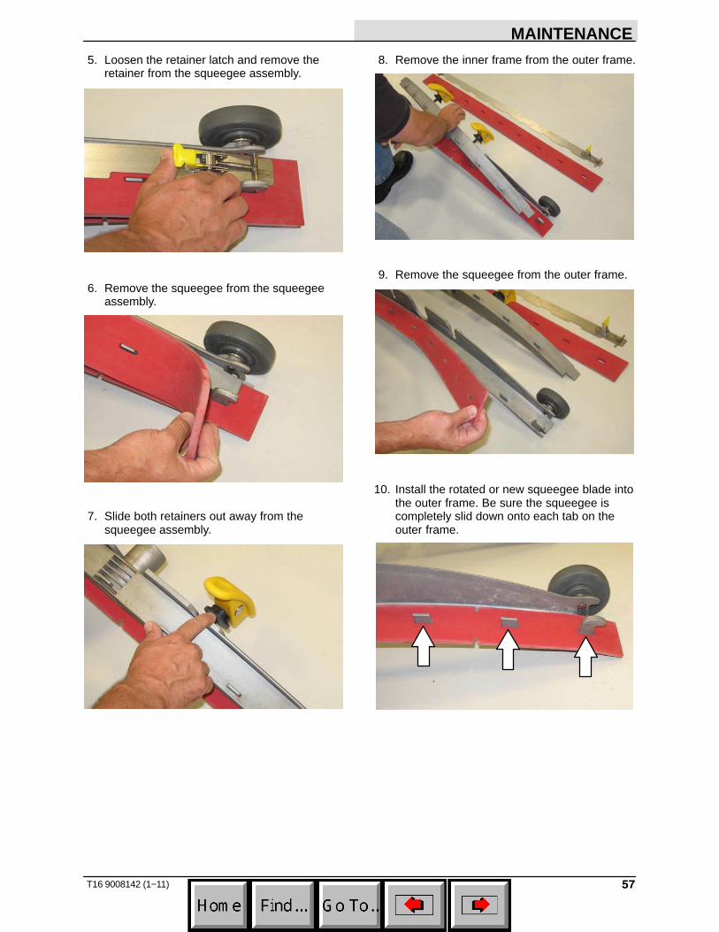
5. Loosen the retainer latch and remove theretainer from the squeegee assembly.
6. Remove the squeegee from the squeegeeassembly.
7. Slide both retainers out away from thesqueegee assembly.
8. Remove the inner frame from the outer frame.
9. Remove the squeegee from the outer frame.
10. Install the rotated or new squeegee blade intothe outer frame. Be sure the squeegee iscompletely slid down onto each tab on theouter frame.
MAINTENANCE
58 T16 9008142 (1−11)
11. Install the inner frame over the squeegee andonto the outer frame. Be sure the inner frameis tight against the top of the outer frame.
12. Slide both retainers into the squeegeeassembly.
13. Place the rotated or new squeegee blade ontothe inner frame. Be sure the squeegee issecurely attached on each tab on the innerframe.
14. Insert the hinge end of the retainer into thehooks in the inner frame.
15. Install the retainer along the rest of thesqueegee assembly and fasten the latch ontothe other end of the squeegee assembly.
MAINTENANCE
59T16 9008142 (1−11)
LEVELING THE REAR SQUEEGEE
Leveling the squeegee ensures the entire lengthof the squeegee blade is in even contact with thesurface being scrubbed. Perform this adjustmenton an even and level floor.
1. Lower the squeegee and drive the machineseveral meters (feet) forward and slowly bringthe machine to a stop.
FOR SAFETY: Before leaving or servicingmachine, stop on level surface and turn offmachine.
2. Check the squeegee deflection over the fulllength of the squeegee blade.
3. If the deflection is not the same over the fulllength of the blade, use the tilt adjust knob tomake adjustments.
DO NOT disconnect the vacuum hose fromthe squeegee frame when leveling squeegee.
4. To adjust the squeegee leveling, loosen the tiltlock knob.
5. Turn the squeegee tilt adjust knobcounter-clockwise to decrease the deflectionat the ends of the squeegee blade.
Turn the squeegee tilt adjust knob clockwiseto increase the deflection at the ends of thesqueegee blade.
6. Tighten the tilt lock knob.
7. Drive the machine forward with the squeegeedown to recheck the squeegee bladedeflection if adjustments were made.
8. Readjust the squeegee blade deflection ifnecessary.
MAINTENANCE
60 T16 9008142 (1−11)
ADJUSTING THE REAR SQUEEGEE BLADEDEFLECTION
Deflection is the amount of curl the overallsqueegee blade has when the machine movesforward. The best deflection is when thesqueegee wipes the floor dry with a minimalamount of deflection.
NOTE: Make sure the squeegee is level beforeadjusting the deflection. See LEVELING THEREAR SQUEEGEE.
1. Lower the squeegee and drive the machineseveral meters (feet) forward and slowly bringthe machine to a stop.
FOR SAFETY: Before leaving or servicingmachine, stop on level surface and turn offmachine.
2. Look at the amount of deflection or “curl” ofthe squeegee blade. The correct amount ofdeflection is 12 mm (0.50 in) for scrubbingsmooth floors and 15 mm (0.62 in) for roughfloors.
3. To adjust the overall squeegee bladedeflection, loosen the lock knob.
4. Turn the adjustment knobs counterclockwiseto increase deflection or clockwise todecrease deflection.
5. Retighten the lock knob.
6. Drive the machine forward again to recheckthe squeegee blade deflection.
7. Readjust the squeegee blade deflection ifnecessary.
MAINTENANCE
61T16 9008142 (1−11)
REPLACING OR ROTATING THE SIDESQUEEGEE BLADES
1. If necessary, raise the scrub head.
FOR SAFETY: Before leaving or servicingmachine, stop on level surface and turn offmachine.
2. Open the side squeegee support door.
3. Unhook the retaining band latch from the sidesqueegee assembly.
4. Remove the retaining band from the sidesqueegee assembly.
5. Remove the squeegee from the sidesqueegee assembly.
6. Install the rotated or new rear squeegee bladeonto the side squeegee assembly.
7. Hook the retaining band onto the sidesqueegee assembly.
8. Fasten the retaining band latch onto the sidesqueegee assembly.
9. Repeat for the side squeegee on the otherside of the scrub head.
MAINTENANCE
62 T16 9008142 (1−11)
REPLACING OR ROTATING THE SIDEBRUSH SQUEEGEE BLADES (OPTION)
Check the side brush squeegee blade for damageand wear daily. Replace or rotate the blade if theleading edge is torn or worn half-way through thethickness of the blade.
1. Start the machine and press the side brushswitch.
2. Shut off the machine after the side brushrotates from under the side guard, but beforethe side brush assembly lowers to the floor.
FOR SAFETY: Before leaving or servicingmachine, stop on level surface and turn offmachine.
3. Remove the knobs holding the side brushsqueegee assembly to the machine andremove the squeegee assembly.
4. Loosen the retaining band latch.
MAINTENANCE
63T16 9008142 (3−11)
5. Remove the squeegee blades and retainerfrom the squeegee frame.
NOTE: Observe which squeegee slots wereinstalled on the squeegee frame before removingthe squeegee.
NOTE: The squeegee blade(s) have two sets ofslots for adjusting the squeegee blade deflection.Install / reinstall squeegees so the deflection isapproximately 12 mm (0.50 in) for smooth floorsand 15 mm (0.62 in) for rough floors.
6. Install the rotated / new squeegee blades andretainer onto the side brush assembly.
7. Fasten the side brush retaining band latch.
8. Reinstall the side brush squeegee assemblyonto the side brush assembly.
MAINTENANCE
64 T16 9008142 (1−11)
SKIRTS AND SEALS
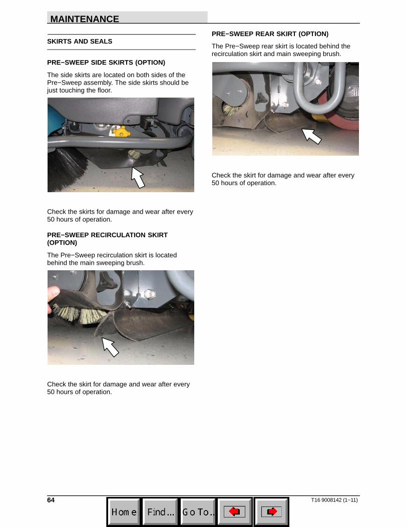
PRE−SWEEP SIDE SKIRTS (OPTION)
The side skirts are located on both sides of thePre−Sweep assembly. The side skirts should bejust touching the floor.
Check the skirts for damage and wear after every50 hours of operation.
PRE−SWEEP RECIRCULATION SKIRT(OPTION)
The Pre−Sweep recirculation skirt is locatedbehind the main sweeping brush.
Check the skirt for damage and wear after every50 hours of operation.
PRE−SWEEP REAR SKIRT (OPTION)
The Pre−Sweep rear skirt is located behind therecirculation skirt and main sweeping brush.
Check the skirt for damage and wear after every50 hours of operation.
MAINTENANCE
65T16 9008142 (12−11)
BELTS AND CHAINS
STEERING CHAIN
The steering chain is located on the steeringcolumn directly under the control panel. Thereshould be no slack in the chain. Check thesteering chain tension after every 200 hours andcheck for damage and wear.
CYLINDRICAL BRUSH DRIVE BELTS
The brush drive belts are located on thecylindrical brush scrub head. Check the belts fordamage and wear after every 200 hours ofoperation.
PRE−SWEEP BRUSH DRIVE BELT (OPTION)
The Pre−Sweep brush drive belt is located insidethe Pre−Sweep assembly on the right side of thecylindrical brush. Check the belt for damage andwear after every 200 hours of operation.
TIRES
The machine has three solid rubber tires: one infront, and two in the rear of the machine. Checktires for damage and wear after every 500 hoursof operation.
MAINTENANCE
66 T16 9008142 (1−11)
PUSHING, TOWING, AND TRANSPORTINGTHE MACHINE
PUSHING OR TOWING THE MACHINE
If the machine becomes disabled, it can bepushed or towed from the front or rear.
The parking brake must be disabled before towingor pushing the machine. To disable the brake,insert the tip of a small screw driver between theelectronic brake lever and the hub. The machinecan move freely when the parking brake isdisabled.
Only push or tow the machine for a very shortdistance and do not exceed 3.2 kp/h (2 mph). It isNOT intended to be pushed or towed for a longdistance or at a high speed.
ATTENTION! Do not push or tow machine fora long distance or damage may occur to thepropelling system.
Immediately after pushing the machine, removethe screw driver from between the electronicbrake lever and the hub. NEVER operate themachine with the parking brake disabled.
FOR SAFETY: Do not operate machine withbrake disabled.
TRANSPORTING THE MACHINE
1. Position the machine at the loading edge ofthe truck or trailer.
FOR SAFETY: Use truck or trailer that willsupport the weight of the machine.
NOTE: Empty the recovery and solution tanksbefore transporting the machine.
2. If the loading surface is not horizontal or ishigher than 380 mm (15 in) from the ground,use a winch to load machine.
If the loading surface is horizontal AND is 380 mm (15 in) or less from the ground, themachine may be driven onto the truck ortrailer.
3. To winch the machine onto the truck or trailer,attach the winching chains to the stabilizerlegs.
FOR SAFETY: When unloading machine offtruck or trailer, use winch. Do not drive themachine off the truck or trailer unless theloading surface is horizontal AND 380 mm (15 in) or less from the ground.
4. Position the machine onto the truck or traileras far as possible. If the machine starts toveer off the center line of the truck or trailer,stop and turn the steering wheel to center themachine.
MAINTENANCE
67T16 9008142 (1−11)
5. Lower the scrub head and block the machinetires. Tie down the machine to the truck ortrailer before transporting.
The front tie-down locations are the stabilizerlegs.
The rear tie-down locations are the holes inthe frame.
6. If the loading surface is not horizontal or ishigher than 380 mm (15 in) from the ground,use a winch to unload machine.
If the loading surface is horizontal AND is 380 mm (15 in) or less from the ground, themachine may be driven off the truck or trailer.
FOR SAFETY: When unloading machine offtruck or trailer, use winch. Do not drive themachine off the truck or trailer unless theloading surface is horizontal AND 380 mm (15 in) or less from the ground.
MAINTENANCE
68 T16 9008142 (1−11)
MACHINE JACKING
FOR SAFETY: Before leaving or servicingmachine, stop on level surface and turn offmachine.
Empty the recovery and solution tanks beforejacking the machine.
FOR SAFETY: When servicing machine, blockmachine tires before jacking machine up. Usea hoist or jack that will support the weight ofthe machine. Jack machine up at designatedlocations only. Support machine with jackstands.
STORAGE INFORMATION
The following steps should be taken when storingthe machine for extended periods of time.
1. Drain and clean the solution and recoverytanks.
2. Park the machine in a cool, dry area indoors.Do not expose the machine to rain.
3. Remove the batteries, or charge them everythree months.
FOR SAFETY: Before leaving or servicingmachine, stop on level surface and turn offmachine.
1. Machines equipped with FaST: Remove theFaST−PAK.
2. Completely drain the solution tank andrecovery tank.
3. Disconnect the hose from the solenoid valveinlet port located on the bottom of the frameand allow all remaining solution to drain fromthe system.
4. Use between 13.8 − 27.6 kPa (2 − 4 psi) ofcompressed air to blow remaining solutionfrom the disconnected hose.
FOR SAFETY: Wear eye and ear protectionwhen using pressurized air or water.
5. Reconnect the hose to the solenoid valve inletport.
6. Pour 7.6 L (2 gal) of Propylene Glycol Based /Recreational Vehicle (RV) antifreeze into thesolution tank.
7. Turn on the machine
8. Press the 1−STEP button.
9. Repeatedly press the Solution increase button(+) until the solution flow is at the highestsetting.
10. Drive the machine to circulate the RVantifreeze completely through the system.
11. Press the 1−STEP button to turn off thesystem.
12. Machines equipped with the optionalspray nozzle only: Operate the wand for afew seconds to protect the pump.
13. Turn off the machine.
14. The remaining RV antifreeze does not need tobe drained from the solution tank.
MAINTENANCE
70 T16 9008142 (1−11)
PREPARING THE MACHINE FOR OPERATION(MACHINES WITHOUT OPTIONAL ec−H2OSYSTEM)
All Propylene Glycol Based / Recreational Vehicle(RV) Antifreeze must be completely cleaned fromthe scrubbing system before the machine can beused for scrubbing.
FOR SAFETY: Before leaving or servicingmachine, stop on level surface and turn offmachine.
1. Completely drain all Propylene Glycol Based /Recreational Vehicle (RV) antifreeze from thesolution tank.
2. Rinse out the solution tank. Refer toDRAINING AND CLEANING THE SOLUTIONTANK in the OPERATION section forinstructions how to clean the solution tank.
3. Pour 11.4 L (3 gal) of cool clean water into thesolution tank.
4. Turn on the machine
5. Press the 1−STEP button.
6. Repeatedly press the Solution increase button(+) until the solution flow is at the highestsetting.
7. Drive the machine to circulate the clean watercompletely through the system to clean outthe RV antifreeze.
8. Press the 1−STEP button to turn off thesystem.
9. Machines equipped with the optionalspray nozzle only: Operate the wand for afew seconds to clean the RV antifreeze fromthe pump.
10. Turn off the machine.
11. The remaining water does not need to bedrained from the solution tank.
1. Completely drain the solution tank andrecovery tank.
2. Disconnect the hose from the solenoid valveinlet port located on the bottom of the frameand allow all remaining solution to drain fromthe system.
3. Use between 13.8 − 27.6 kPa (2 − 4 psi) ofcompressed air to blow remaining solutionfrom the disconnected hose.
FOR SAFETY: Wear eye and ear protectionwhen using pressurized air or water.
4. Reconnect the hose to the solenoid valve inletport.
5. Lift the operator seat open and engage theseat support bar.
6. Remove the ec−H2O compartment cover.
7. Remove the drain hose from the ec−H2Ocompartment.
8. Disconnect the outlet hose to the scrub headfrom the ec−H2O manifold hose.
9. Connect the drain hose to the ec−H2Omanifold hose disconnected from the outlethose in the previous step.
MAINTENANCE
72 T16 9008142 (1−11)
10. Pour 7.6 L (2 gal) of Propylene Glycol Based /Recreational Vehicle (RV) antifreeze into thesolution tank.
11. Place the ec−H2O system outlet hose into anempty container.
12. Press and release the flush switch on theec−H2O module to cycle the RV antifreezethrough ec−H2O system. When the antifreezeappears in the container, press the switchagain to turn off the module.
13. Disconnect the drain hose from the ec−H2Omanifold hose.
14. Reconnect the outlet hose to the scrub headto the ec−H2O manifold hose.
15. Place the drain hose back into the ec−H2Ocompartment.
16. Reinstall the ec−H2O compartment cover.
17. Close the operator seat cover.
MAINTENANCE
73T16 9008142 (1−11)
PRIMING THE ec−H2O SYSTEM
Prime the ec−H2O system if the machine hasbeen stored for a long period with no water in thesolution tank / ec−H2O system.
FOR SAFETY: Before leaving or servicingmachine, stop on level surface and turn offmachine.
1. Fill the solution tank with clean cool water.See FILLING THE SOLUTION TANK sectionof this manual.
2. Remove the ec−H2O compartment cover.
3. Remove the drain hose from the ec−H2Ocompartment.
4. Disconnect the outlet hose to the scrub headfrom the ec−H2O manifold hose.
5. Place the drain hose into an empty container.
6. Turn on the machine.
7. Press and release the ec−H2O module flushswitch. Allow the system to drain water intothe container for 2 minutes.
8. Press the ec−H2O module flush switch toshut off the system.
9. Disconnect the drain hose from the ec−H2Omanifold hose.
10. Reconnect the outlet hose to the scrub headto ec−H2O manifold hose.
11. Place the drain hose back into the ec−H2Ocompartment.
12. Reinstall the ec−H2O compartment cover.
13. Close the operator seat cover.
SPECIFICATIONS
74 T16 9008142 (1−11)
SPECIFICATIONS
GENERAL MACHINE DIMENSIONS/CAPACITIES
Item Dimension/capacity
Length 1880 mm (74 in)
Length (with Pre−Sweep) 2510 mm (99 in)
Width (less squeegee) 1040 mm (41 in)
Width (with squeegee) 1070 mm (42 in)
Width (with side brush) 1170 mm (46 in)
Height 1475 mm (58 in)
Height with overhead guard 2080 mm (82 in)
Disk brush diameter for side brush (option) 330 mm (13 in)
Disk brush diameter for Pre−Sweep (option) 460 mm (18 in)
Disk brush diameter 460 mm (18 in)
Cylindrical sweep brush diameter for Pre−Sweep (option) 200 mm (8 in)
Cylindrical sweep brush length for Pre−Sweep (option) 610 mm (24 in)
Cylindrical scrub brush diameter 205 mm (8 in)
Cylindrical brush length 910 mm (36 in)
Scrubbing path width 910 mm (36 in)
Solution tank capacity 190 L (50 gallons)
Solution tank capacity (with optional ES system) 280 L (75 gallons)
Recovery tank capacity 225 L (60 gallons)
Weight (Empty) 500 Kg (1100 lbs)
Weight (with standard 235 AH batteries) 860 Kg (1900 lbs)