The boiler meets requirements of Statutory Instrument “The Boiler(Efficiency) Regulations 1993 No 3083” and is deemed to meet therequirements of Directive 92/42/EEC on the efficiency requirements fornew hot water boilers fired with liquid or gaseous fuels:-
Type test for purpose of Regulation 5 certified by: Notified Body 0086.
Product/Production certified by:Notified Body 0086.
For GB / IE only.
IMPORTANT - Installation, Commissioning, Service & Repair
This appliance must be installed in accordance with themanufacturer’s instructions and the regulations in force. Read theinstructions fully before installing or using the appliance.
In GB, this must be carried out by a competent person as statedin the Gas Safety (Installation & Use) Regulations.
Definition of competence: A person who works for a Gas Saferegistered company and holding current certificates in therelevant ACS modules, is deemed competent.
In IE, this must be carried out by a competent person as stated inI.S. 813 “Domestic Gas Installations”.
Lifting - This product should be lifted and handled by twopeople. Stooping should be avoided and protectiveequipment worn where necessary. Carrying & liftingequipment should be used as required, e.g. when installing ina loft space.
Codes of Practice, most recent version should be used
In GB the following Codes of Practice apply:Standard ScopeBS 6891 Gas Installation.BS 5546 Installation of hot water supplies for
domestic purposes.BS 5449 Part 1 Forced circulation hot water systems.BS 6798 Installation of gas fired hot water boilers.BS 5440 Part 1 Flues.BS 5440 Part 2 Ventilation.BS 7593 Treatment of water in domestic hot water
central heating systems.BS 4814 Expansion vessels for hot water systems.BS 6283 Safety and control devices for use in hot
water systems.
In IE the following Codes of Practice apply:Standard ScopeI.S. 813 Domestic Gas Installations.The following BS standards give valuable additional information;BS 5546 Installation of hot water supplies for
domestic purposes.BS 5449 Part 1 Forced circulation hot water systems.BS 7593 Treatment of water in domestic hot water
central heating systems.
IMPORTANT - The addition of anything that may interferewith the normal operation of the appliance without expresswritten permission from the manufacturer or his agentcould invalidate the appliance warranty. In GB this couldalso infringe the GAS SAFETY (Installation and Use)REGULATIONS.
Applications for the copyright owner’s permission to reproduce or make other use of anypart of this publication should be made, giving details of the proposed use, to the followingaddress:
The Company Secretary, Baxi Heating UK Ltd, The Wyvern Business Park, Stanier Way, Derby, DE21 6BF.
Full acknowledgement of author and source must be given.
WARNING: Any person who does any unauthorised act in relation to a copyright work maybe liable to criminal prosecution and civil claims for damages.
0086ISO 9001FM 00866
All Gas Safe registered engineers carry an ID card with theirlicence number and a photograph. You can check your engineeris registered by telephoning 0800 408 5500 or online atwww.GasSafeRegistered.co.uk
The Benchmark Scheme
Benchmark places responsibilities on both manufacturers and installers. The purpose is toensure that customers are provided with the correct equipment for their needs, that it isinstalled, commissioned and serviced in accordance with the manufacturer’s instructions bycompetent persons and that it meets the requirements of the appropriate BuildingRegulations. The Benchmark Checklist can be used to demonstrate compliance with BuildingRegulations and should be provided to the customer for future reference.
Installers are required to carry out installation, commissioning and servicing work inaccordance with the Benchmark Code of Practice which is available from the Heating andHotwater Industry Council who manage and promote the Scheme. Visitwww.centralheating.co.uk for more information.
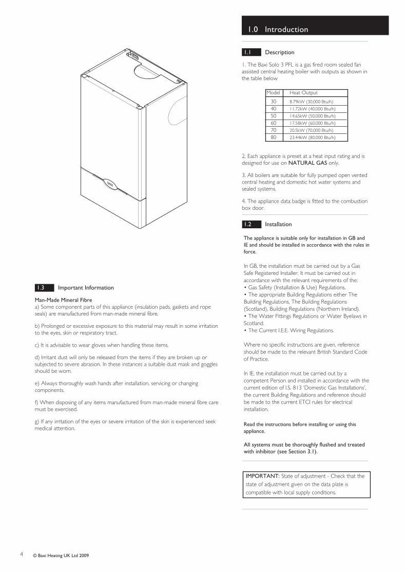
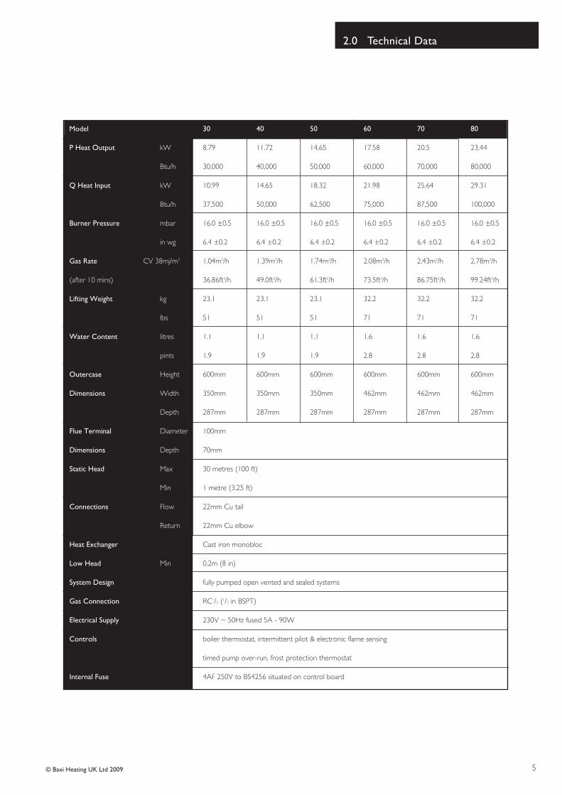
1. The Baxi Solo 3 PFL is a gas fired room sealed fanassisted central heating boiler with outputs as shown inthe table below
2. Each appliance is preset at a heat input rating and isdesigned for use on NATURAL GAS only.
3. All boilers are suitable for fully pumped open ventedcentral heating and domestic hot water systems andsealed systems.
4. The appliance data badge is fitted to the combustionbox door.
1.2 Installation
The appliance is suitable only for installation in GB andIE and should be installed in accordance with the rules inforce.
In GB, the installation must be carried out by a GasSafe Registered Installer. It must be carried out inaccordance with the relevant requirements of the:• Gas Safety (Installation & Use) Regulations.• The appropriate Building Regulations either TheBuilding Regulations, The Building Regulations(Scotland), Building Regulations (Northern Ireland).• The Water Fittings Regulations or Water Byelaws inScotland.• The Current I.E.E. Wiring Regulations.
Where no specific instructions are given, referenceshould be made to the relevant British Standard Codeof Practice.
In IE, the installation must be carried out by acompetent Person and installed in accordance with thecurrent edition of I.S. 813 ‘Domestic Gas Installations’,the current Building Regulations and reference shouldbe made to the current ETCI rules for electricalinstallation.
Read the instructions before installing or using thisappliance.
All systems must be thoroughly flushed and treatedwith inhibitor (see Section 3.1).
1.3 Important Information
Man-Made Mineral Fibrea) Some component parts of this appliance (insulation pads, gaskets and ropeseals) are manufactured from man-made mineral fibre.
b) Prolonged or excessive exposure to this material may result in some irritationto the eyes, skin or respiratory tract.
c) It is advisable to wear gloves when handling these items.
d) Irritant dust will only be released from the items if they are broken up orsubjected to severe abrasion. In these instances a suitable dust mask and gogglesshould be worn.
e) Always thoroughly wash hands after installation, servicing or changingcomponents.
f) When disposing of any items manufactured from man-made mineral fibre caremust be exercised.
g) If any irritation of the eyes or severe irritation of the skin is experienced seekmedical attention.
IMPORTANT: State of adjustment - Check that thestate of adjustment given on the data plate iscompatible with local supply conditions.
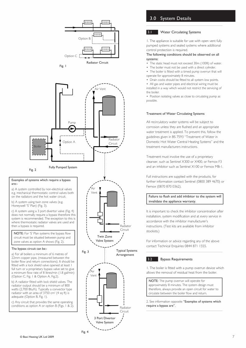
a) A system controlled by non-electrical valvese.g. mechanical thermostatic control valves bothon the radiators and the hot water circuit.
b) A system using twin zone valves (e.g.Honeywell 'S' Plan) (Fig. 3).
c) A system using a 3 port divertor valve (Fig. 4)does not normally require a bypass therefore thissystem is recommended. The exception to this iswhere thermostatic radiator valves are used andthen a bypass is required.
NOTE: For ‘S’ Plan systems the bypass flowcircuit must be situated between pump andzone valves as option A shows (Fig. 2).
The bypass circuit can be:-
a) For all boilers a minimum of 6 metres of22mm copper pipe, (measured between theboiler flow and return connections). It should befitted with a lock shield valve opened at least 1full turn or a proprietary bypass valve set to givea minimum flow rate of 8 litres/min (1.8 gal/min)(Option C, Fig. 1 & Option A, Fig.2).
b) A radiator fitted with lock shield valves. Theradiator output should be a minimum of 800watts (2,700 Btu/h). Typically a convector typeradiator with an area of 3750 cm2 (4 sq ft) isadequate (Option B, Fig. 1).
c) Any circuit that provides the same operatingconditions as option A or option B (Figs. 1 & 2).
3.1 Water Circulating Systems
1. The appliance is suitable for use with open vent fullypumped systems and sealed systems where additionalcontrol protection is required.The following conditions should be observed on allsystems:• The static head must not exceed 30m (100ft) of water.• The boiler must not be used with a direct cylinder.• The boiler is fitted with a timed pump overrun that willoperate for approximately 8 minutes.• Drain cocks should be fitted to all system low points.• All gas and water pipes and electrical wiring must beinstalled in a way which would not restrict the servicing ofthe boiler.• Position isolating valves as close to circulating pump aspossible.
Treatment of Water Circulating Systems
All recirculatory water systems will be subject tocorrosion unless they are flushed and an appropriatewater treatment is applied. To prevent this, follow theguidelines given in BS 7593 “Treatment of Water inDomestic Hot Water Central Heating Systems” and thetreatment manufacturers instructions.
Treatment must involve the use of a proprietarycleanser, such as Sentinel X300 or X400, or Fernox F3and an inhibitor such as Sentinel X100 or Fernox MB-1.
Full instructions are supplied with the products, forfurther information contact Sentinel (0800 389 4670) orFernox (0870 870 0362).
Failure to flush and add inhibitor to the system willinvalidate the appliance warranty.
It is important to check the inhibitor concentration afterinstallation, system modification and at every service inaccordance with the inhibitor manufacturer’sinstructions. (Test kits are available from inhibitorstockists.)
For information or advice regarding any of the abovecontact Technical Enquiries 0844 871 1555.
3.2 Bypass Requirements
1. The boiler is fitted with a pump overrun device whichallows the removal of residual heat from the boiler.
NOTE: The pump overrun will operate forapproximately 8 minutes. The system design musttherefore, always provide an open circuit for water tocirculate between the boiler flow and return.
2. See information opposite “Examples of systems whichrequire a bypass are”.
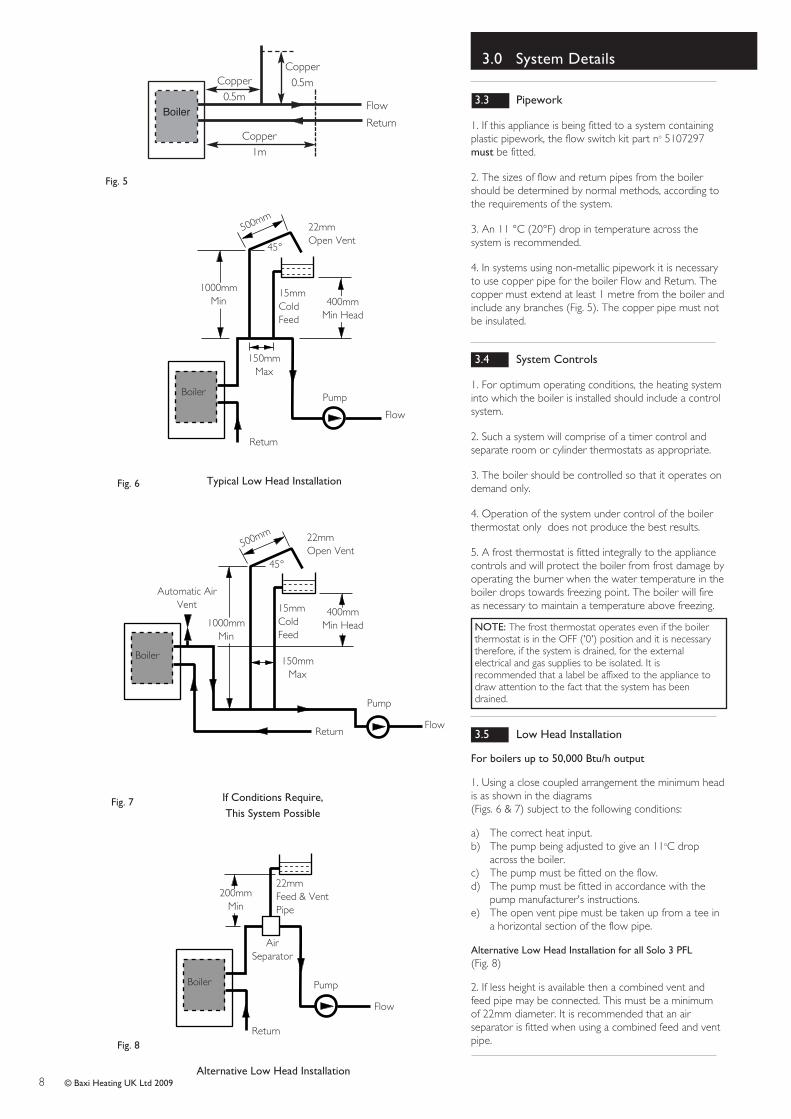
1. If this appliance is being fitted to a system containingplastic pipework, the flow switch kit part no 5107297must be fitted.
2. The sizes of flow and return pipes from the boilershould be determined by normal methods, according tothe requirements of the system.
3. An 11 °C (20°F) drop in temperature across thesystem is recommended.
4. In systems using non-metallic pipework it is necessaryto use copper pipe for the boiler Flow and Return. Thecopper must extend at least 1 metre from the boiler andinclude any branches (Fig. 5). The copper pipe must notbe insulated.
3.4 System Controls
1. For optimum operating conditions, the heating systeminto which the boiler is installed should include a controlsystem.
2. Such a system will comprise of a timer control andseparate room or cylinder thermostats as appropriate.
3. The boiler should be controlled so that it operates ondemand only.
4. Operation of the system under control of the boilerthermostat only does not produce the best results.
5. A frost thermostat is fitted integrally to the appliancecontrols and will protect the boiler from frost damage byoperating the burner when the water temperature in theboiler drops towards freezing point. The boiler will fireas necessary to maintain a temperature above freezing.
NOTE: The frost thermostat operates even if the boilerthermostat is in the OFF ('0') position and it is necessarytherefore, if the system is drained, for the externalelectrical and gas supplies to be isolated. It isrecommended that a label be affixed to the appliance todraw attention to the fact that the system has beendrained.
3.5 Low Head Installation
For boilers up to 50,000 Btu/h output
1. Using a close coupled arrangement the minimum headis as shown in the diagrams (Figs. 6 & 7) subject to the following conditions:
a) The correct heat input.b) The pump being adjusted to give an 11oC drop
across the boiler.c) The pump must be fitted on the flow.d) The pump must be fitted in accordance with the
pump manufacturer's instructions.e) The open vent pipe must be taken up from a tee in
a horizontal section of the flow pipe.
Alternative Low Head Installation for all Solo 3 PFL(Fig. 8)
2. If less height is available then a combined vent andfeed pipe may be connected. This must be a minimumof 22mm diameter. It is recommended that an airseparator is fitted when using a combined feed and ventpipe.
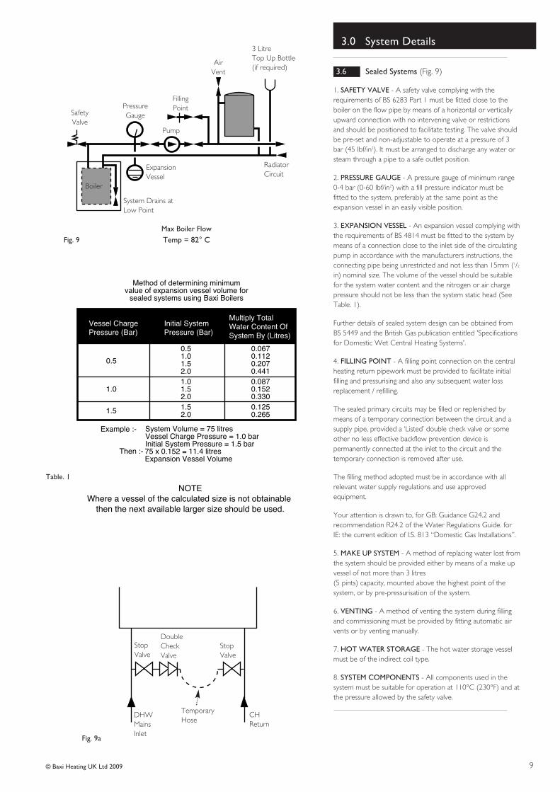
1. SAFETY VALVE - A safety valve complying with therequirements of BS 6283 Part 1 must be fitted close to theboiler on the flow pipe by means of a horizontal or verticallyupward connection with no intervening valve or restrictionsand should be positioned to facilitate testing. The valve shouldbe pre-set and non-adjustable to operate at a pressure of 3bar (45 Ibf/in2). It must be arranged to discharge any water orsteam through a pipe to a safe outlet position.
2. PRESSURE GAUGE - A pressure gauge of minimum range0-4 bar (0-60 Ibf/in2) with a fill pressure indicator must befitted to the system, preferably at the same point as theexpansion vessel in an easily visible position.
3. EXPANSION VESSEL - An expansion vessel complying withthe requirements of BS 4814 must be fitted to the system bymeans of a connection close to the inlet side of the circulatingpump in accordance with the manufacturers instructions, theconnecting pipe being unrestricted and not less than 15mm (1/2
in) nominal size. The volume of the vessel should be suitablefor the system water content and the nitrogen or air chargepressure should not be less than the system static head (SeeTable. 1).
Further details of sealed system design can be obtained fromBS 5449 and the British Gas publication entitled 'Specificationsfor Domestic Wet Central Heating Systems'.
4. FILLING POINT - A filling point connection on the centralheating return pipework must be provided to facilitate initialfilling and pressurising and also any subsequent water lossreplacement / refilling.
The sealed primary circuits may be filled or replenished bymeans of a temporary connection between the circuit and asupply pipe, provided a ‘Listed’ double check valve or someother no less effective backflow prevention device ispermanently connected at the inlet to the circuit and thetemporary connection is removed after use.
The filling method adopted must be in accordance with allrelevant water supply regulations and use approvedequipment.
Your attention is drawn to, for GB: Guidance G24.2 andrecommendation R24.2 of the Water Regulations Guide. forIE: the current edition of I.S. 813 “Domestic Gas Installations”.
5. MAKE UP SYSTEM - A method of replacing water lost fromthe system should be provided either by means of a make upvessel of not more than 3 litres (5 pints) capacity, mounted above the highest point of thesystem, or by pre-pressurisation of the system.
6. VENTING - A method of venting the system during fillingand commissioning must be provided by fitting automatic airvents or by venting manually.
7. HOT WATER STORAGE - The hot water storage vesselmust be of the indirect coil type.
8. SYSTEM COMPONENTS - All components used in thesystem must be suitable for operation at 110°C (230°F) and atthe pressure allowed by the safety valve.
Initial System�Pressure (Bar)
Vessel Charge�Pressure (Bar)
Multiply Total�Water Content Of�System By (Litres)
1. The appliance may be fitted to any suitable wall with theflue passing through an outside wall and discharging toatmosphere in a position permitting satisfactory removal ofcombustion products and providing an adequate air supply.The appliance should be fitted within the building unlessotherwise protected by a suitable enclosure ie. garage orouthouse. (The appliance may be fitted inside a cupboard,see section 4.5.)
2. If the appliance is fitted in a room containing a bath orshower reference must be made to the relevantrequirements.In GB this is the current I.E.E. Wiring Regulations andBuilding Regulations. In IE reference should be made to the current edition of I.S.813 “Domestic Gas Installations” and the current ETCIrules.
3. If the appliance is to be fitted into a building of timberframe construction then reference must be made to thecurrent edition of Institution of Gas Engineers PublicationIGE/UP/7 (Gas Installations in Timber Framed Housing).
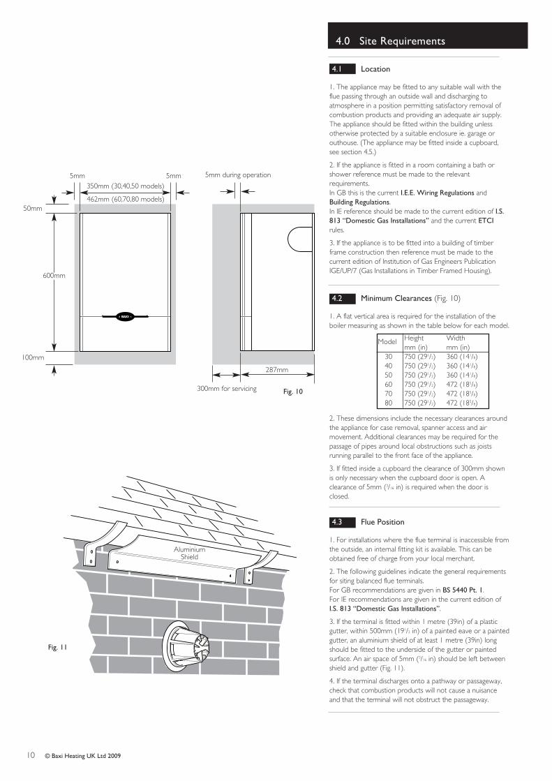
4.2 Minimum Clearances (Fig. 10)
1. A flat vertical area is required for the installation of theboiler measuring as shown in the table below for each model.
2. These dimensions include the necessary clearances aroundthe appliance for case removal, spanner access and airmovement. Additional clearances may be required for thepassage of pipes around local obstructions such as joistsrunning parallel to the front face of the appliance.
3. If fitted inside a cupboard the clearance of 300mm shownis only necessary when the cupboard door is open. Aclearance of 5mm (3/16 in) is required when the door isclosed.
4.3 Flue Position
1. For installations where the flue terminal is inaccessible fromthe outside, an internal fitting kit is available. This can beobtained free of charge from your local merchant.
2. The following guidelines indicate the general requirementsfor siting balanced flue terminals.For GB recommendations are given in BS 5440 Pt. 1.For IE recommendations are given in the current edition ofI.S. 813 “Domestic Gas Installations”.
3. If the terminal is fitted within 1 metre (39in) of a plasticgutter, within 500mm (191/2 in) of a painted eave or a paintedgutter, an aluminium shield of at least 1 metre (39in) longshould be fitted to the underside of the gutter or paintedsurface. An air space of 5mm (3/16 in) should be left betweenshield and gutter (Fig. 11).
4. If the terminal discharges onto a pathway or passageway,check that combustion products will not cause a nuisanceand that the terminal will not obstruct the passageway.
WARNING - The addition of anything that mayinterfere with the normal operation of the appliancewithout the express written permission from themanufacturer or his agent could invalidate theappliance warranty and infringe the GAS SAFETY(Installation and Use) REGULATIONS.
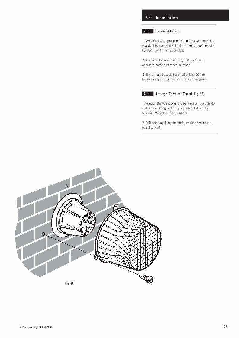
If a terminal is less than 2 metres above a balcony,above ground or above a flat roof to which peoplehave access then a suitable terminal guard must beprovided.
5. If the outer surface of an outside wall is of combustible
material, it should be protected by fitting the flue trim
provided.
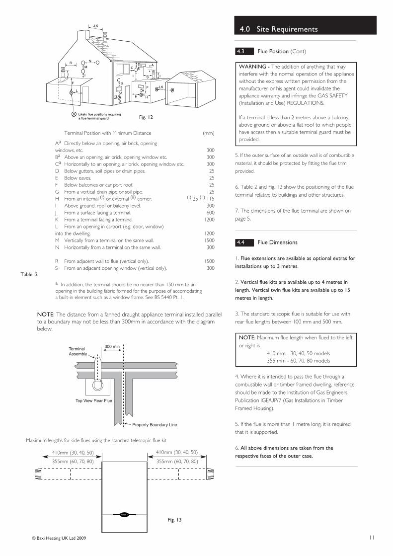
6. Table 2 and Fig. 12 show the positioning of the flueterminal relative to buildings and other structures.
7. The dimensions of the flue terminal are shown onpage 5.
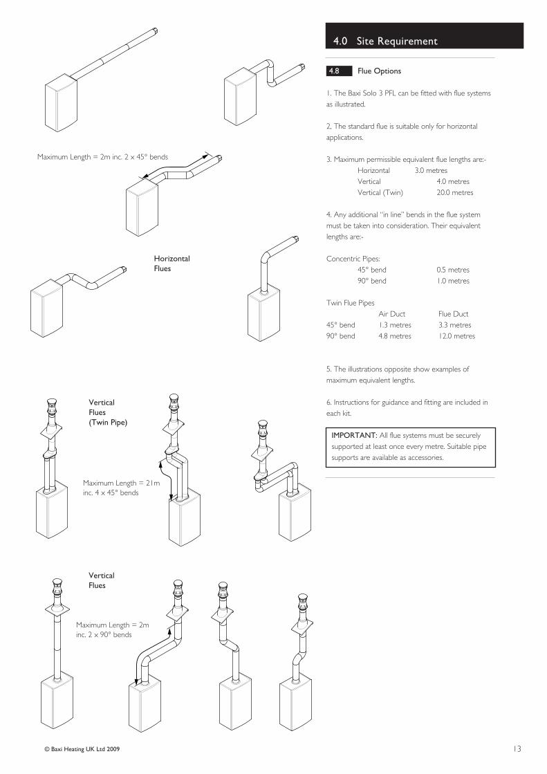
4.4 Flue Dimensions
1. Flue extensions are available as optional extras forinstallations up to 3 metres.
2. Vertical flue kits are available up to 4 metres inlength. Vertical twin flue kits are available up to 15metres in length.
3. The standard telscopic flue is suitable for use withrear flue lengths between 100 mm and 500 mm.
NOTE: Maximum flue length when flued to the leftor right is
410 mm - 30, 40, 50 models355 mm - 60, 70, 80 models
4. Where it is intended to pass the flue through acombustible wall or timber framed dwelling, referenceshould be made to the Institution of Gas EngineersPublication IGE/UP/7 (Gas Installations in TimberFramed Housing).
5. If the flue is more than 1 metre long, it is requiredthat it is supported.
6. All above dimensions are taken from therespective faces of the outer case.
Table. 2
Fig. 13
Fig. 12
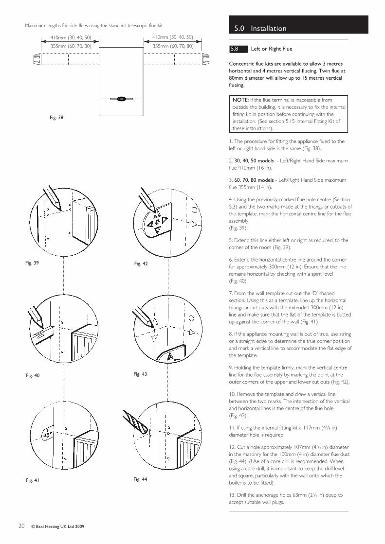
Maximum lengths for side flues using the standard telescopic flue kit
410mm (30, 40, 50) 410mm (30, 40, 50)
355mm (60, 70, 80) 355mm (60, 70, 80)
Terminal Position with Minimum Distance (mm)
Aa Directly below an opening, air brick, opening windows, etc. 300Ba Above an opening, air brick, opening window etc. 300Ca Horizontally to an opening, air brick, opening window etc. 300D Below gutters, soil pipes or drain pipes. 25E Below eaves. 25F Below balconies or car port roof. 25G From a vertical drain pipe or soil pipe. 25H From an internal (i) or external (ii) corner. (i) 25 (ii) 115I Above ground, roof or balcony level. 300J From a surface facing a terminal. 600K From a terminal facing a terminal. 1200L From an opening in carport (e.g. door, window) into the dwelling. 1200M Vertically from a terminal on the same wall. 1500N Horizontally from a terminal on the same wall. 300
R From adjacent wall to flue (vertical only). 1500S From an adjacent opening window (vertical only). 300
N
I
I
G
F
M
I
AA
F
H
J,K
DE
H
Likely flue positions requiring a flue terminal guard
C
RA
I
J,K
I
L
S
B
300 minTerminal�Assembly
Top View Rear Flue
Property Boundary Line
NOTE: The distance from a fanned draught appliance terminal installed parallelto a boundary may not be less than 300mm in accordance with the diagrambelow.
a In addition, the terminal should be no nearer than 150 mm to an opening in the building fabric formed for the purpose of accomodating a built-in element such as a window frame. See BS 5440 Pt. 1.
1. Where the appliance is installed in a cupboard orcompartment, no air vents are required. The Solo 3PFL will run sufficiently cool without ventilation.
NOTE: The ventilation label on the front of theouter case MUST NOT BE REMOVED when theappliance is installed in a compartment orcupboard.
2. B.S. 5440 refers to room sealed appliances installedin compartments.
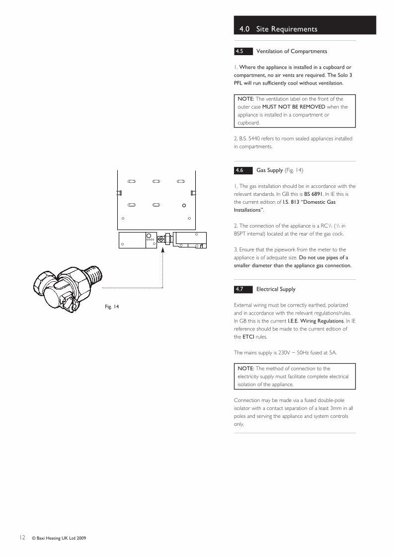
4.6 Gas Supply (Fig. 14)
1. The gas installation should be in accordance with therelevant standards. In GB this is BS 6891. In IE this isthe current edition of I.S. 813 “Domestic GasInstallations”.
2. The connection of the appliance is a RC1/2 (1/2 inBSPT internal) located at the rear of the gas cock.
3. Ensure that the pipework from the meter to theappliance is of adequate size. Do not use pipes of asmaller diameter than the appliance gas connection.
4.7 Electrical Supply
External wiring must be correctly earthed, polarizedand in accordance with the relevant regulations/rules.In GB this is the current I.E.E. Wiring Regulations. In IEreference should be made to the current edition ofthe ETCI rules.
The mains supply is 230V ~ 50Hz fused at 5A.
NOTE: The method of connection to theelectricity supply must facilitate complete electricalisolation of the appliance.
Connection may be made via a fused double-poleisolator with a contact separation of a least 3mm in allpoles and serving the appliance and system controlsonly.
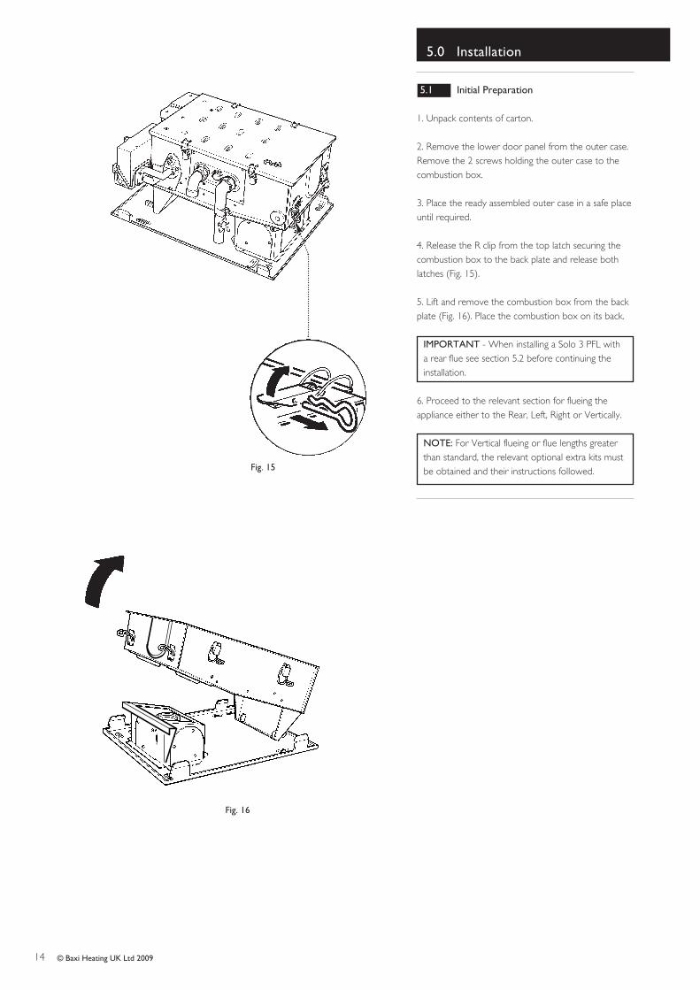
2. Remove the lower door panel from the outer case.Remove the 2 screws holding the outer case to thecombustion box.
3. Place the ready assembled outer case in a safe placeuntil required.
4. Release the R clip from the top latch securing thecombustion box to the back plate and release bothlatches (Fig. 15).
5. Lift and remove the combustion box from the backplate (Fig. 16). Place the combustion box on its back.
IMPORTANT - When installing a Solo 3 PFL witha rear flue see section 5.2 before continuing theinstallation.
6. Proceed to the relevant section for flueing theappliance either to the Rear, Left, Right or Vertically.
NOTE: For Vertical flueing or flue lengths greaterthan standard, the relevant optional extra kits mustbe obtained and their instructions followed.Fig. 15
1. Release the four latches holding the combustion boxdoor (Fig 18). Remove the combustion box door bypulling forward (Fig. 17).
2. Release the 5-pin electrical plug connecting thepressure switch and fan (Fig. 19). Withdraw the fanassembly by pulling forwards from the top edge (Fig. 17).
3. Take the sheetmetal restrictor (supplied in the kit ofparts), check that the number stamped on the restrictormatches the appliance (e.g. 50 stamped on the restrictoris for PFL 50 appliance).
4. Fit the restrictor to the fan outlet flange, bending the 3lugs equally ensuring the restrictor seals against the fanoutlet flange (Fig. 20).
5. Re-assemble the fan assembly and combustion boxdoor ensuring that the flexible tubes from the fan unit tothe pressure switch are routed correctly and that theyare not kinked or flattened (Fig. 21).
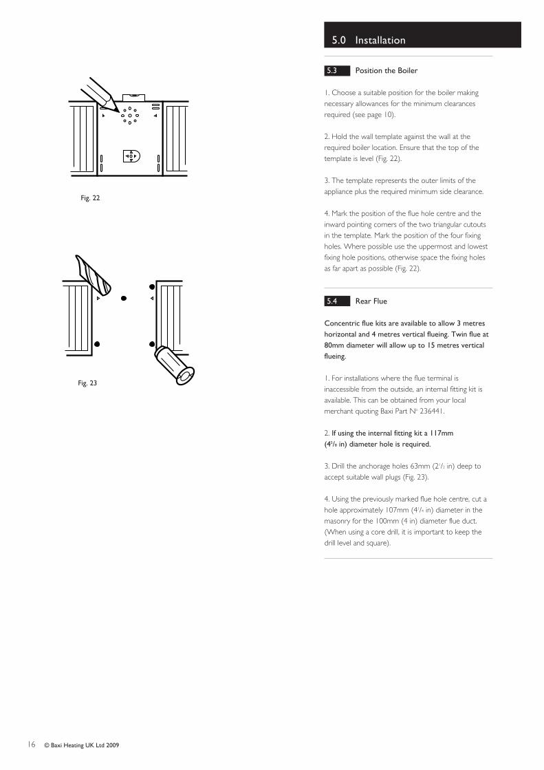
1. Choose a suitable position for the boiler makingnecessary allowances for the minimum clearancesrequired (see page 10).
2. Hold the wall template against the wall at therequired boiler location. Ensure that the top of thetemplate is level (Fig. 22).
3. The template represents the outer limits of theappliance plus the required minimum side clearance.
4. Mark the position of the flue hole centre and theinward pointing corners of the two triangular cutoutsin the template. Mark the position of the four fixingholes. Where possible use the uppermost and lowestfixing hole positions, otherwise space the fixing holesas far apart as possible (Fig. 22).
5.4 Rear Flue
Concentric flue kits are available to allow 3 metreshorizontal and 4 metres vertical flueing. Twin flue at80mm diameter will allow up to 15 metres verticalflueing.
1. For installations where the flue terminal isinaccessible from the outside, an internal fitting kit isavailable. This can be obtained from your localmerchant quoting Baxi Part No 236441.
2. If using the internal fitting kit a 117mm (45/8 in) diameter hole is required.
3. Drill the anchorage holes 63mm (21/2 in) deep toaccept suitable wall plugs (Fig. 23).
4. Using the previously marked flue hole centre, cut ahole approximately 107mm (41/4 in) diameter in themasonry for the 100mm (4 in) diameter flue duct.(When using a core drill, it is important to keep thedrill level and square).
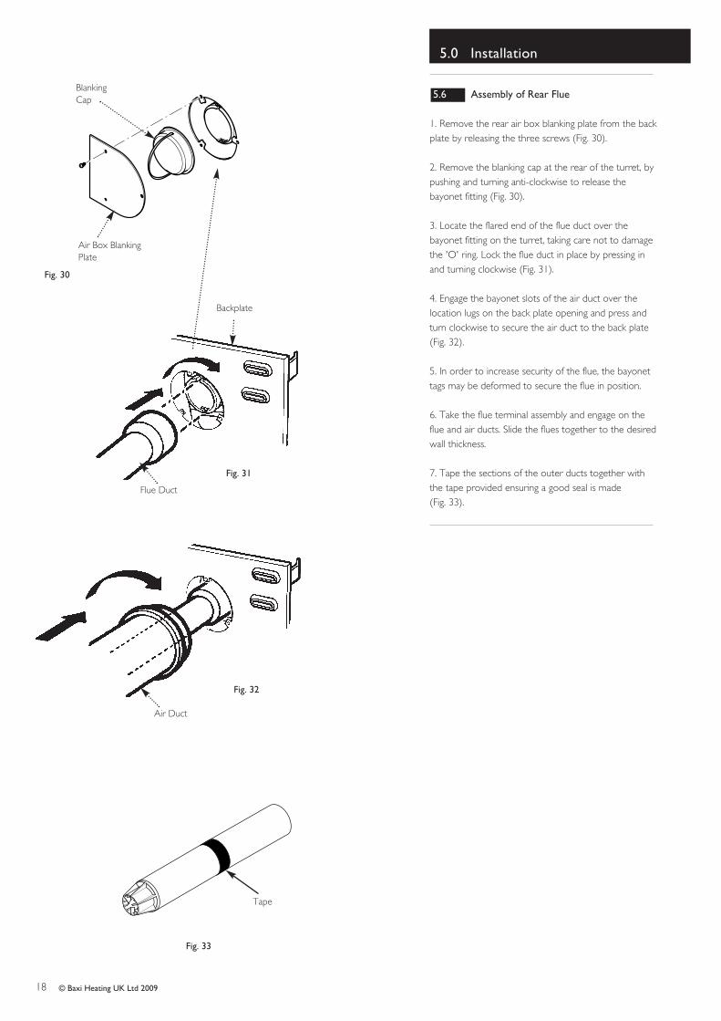
1. Remove the rear air box blanking plate from the backplate by releasing the three screws (Fig. 30).
2. Remove the blanking cap at the rear of the turret, bypushing and turning anti-clockwise to release thebayonet fitting (Fig. 30).
3. Locate the flared end of the flue duct over thebayonet fitting on the turret, taking care not to damagethe 'O' ring. Lock the flue duct in place by pressing inand turning clockwise (Fig. 31).
4. Engage the bayonet slots of the air duct over thelocation lugs on the back plate opening and press andturn clockwise to secure the air duct to the back plate(Fig. 32).
5. In order to increase security of the flue, the bayonettags may be deformed to secure the flue in position.
6. Take the flue terminal assembly and engage on theflue and air ducts. Slide the flues together to the desiredwall thickness.
7. Tape the sections of the outer ducts together withthe tape provided ensuring a good seal is made (Fig. 33).
1. Engage the assembly into the hole previously cut inthe wall and slide in place (Fig. 34).
2. Secure the assembly to the wall at the previouslydrilled anchorage points with suitable screws (Fig. 34).Before finally tightening the screws, check that theassembly is level.
3. Make good between the wall and the air duct outsidethe building if the internal fitting kit has not been used(Fig. 35).
4. The flue trim provided may be fitted if required, toneaten the make-up around the terminal (Fig. 37).
5. To fit the flue terminal trim:
a) The trim should be fitted once the flue is secure.
b) Take the three edge clips from the kit and fit themequi-spaced onto the inner flange of the trim (Fig. 36).
c) With the flanges towards the wall pass the trim overthe terminal. If required a bead of sealant may beapplied to the rear face of the trim.
d) Push firmly on the trim to ensure the edge clipsengage on the flue.
Concentric flue kits are available to allow 3 metreshorizontal and 4 metres vertical flueing. Twin flue at80mm diameter will allow up to 15 metres verticalflueing.
NOTE: If the flue terminal is inaccessible fromoutside the building, it is necessary to fix the internalfitting kit in position before continuing with theinstallation. (See section 5.15 Internal Fitting Kit ofthese instructions).
1. The procedure for fitting the appliance flued to theleft or right hand side is the same (Fig. 38).
2. 30, 40, 50 models - Left/Right Hand Side maximumflue 410mm (16 in).
3. 60, 70, 80 models - Left/Right Hand Side maximumflue 355mm (14 in).
4. Using the previously marked flue hole centre (Section5.3) and the two marks made at the triangular cutouts ofthe template, mark the horizontal centre line for the flueassembly (Fig. 39).
5. Extend this line either left or right as required, to thecorner of the room (Fig. 39).
6. Extend the horizontal centre line around the cornerfor approximately 300mm (12 in). Ensure that the lineremains horizontal by checking with a spirit level (Fig. 40).
7. From the wall template cut out the ‘D’ shapedsection. Using this as a template, line up the horizontaltriangular cut outs with the extended 300mm (12 in)line and make sure that the flat of the template is buttedup against the corner of the wall (Fig. 41).
8. If the appliance mounting wall is out of true, use stringor a straight edge to determine the true corner positionand mark a vertical line to accommodate the flat edge ofthe template.
9. Holding the template firmly, mark the vertical centreline for the flue assembly by marking the point at theouter corners of the upper and lower cut outs (Fig. 42).
10. Remove the template and draw a vertical linebetween the two marks. The intersection of the verticaland horizontal lines is the centre of the flue hole (Fig. 43).
11. If using the internal fitting kit a 117mm (45/8 in)diameter hole is required.
12. Cut a hole approximately 107mm (41/4 in) diameterin the masonry for the 100mm (4 in) diameter flue duct(Fig. 44). (Use of a core drill is recommended. Whenusing a core drill, it is important to keep the drill leveland square, particularly with the wall onto which theboiler is to be fitted).
13. Drill the anchorage holes 63mm (21/2 in) deep toaccept suitable wall plugs.
Fig. 39
Fig. 40
Fig. 41
Fig. 42
Fig. 43
Fig. 44
Maximum lengths for side flues using the standard telescopic flue kit
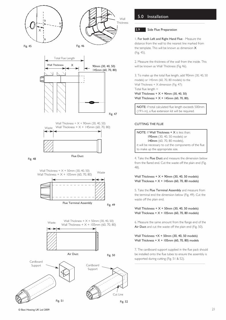
1. For both Left and Right Hand Flue - Measure thedistance from the wall to the nearest line marked fromthe template. This will be known as dimension X(Fig. 45).
2. Measure the thickness of the wall from the inside. Thiswill be known as Wall Thickness (Fig 46).
3. To make up the total flue length, add 90mm (30, 40, 50
models) or 145mm (60, 70, 80 models) to the
Wall Thickness + X dimension (Fig. 47):
Total flue length = Wall Thickness + X + 90mm (30, 40, 50)
Wall Thickness + X + 145mm (60, 70, 80).
NOTE: if total calculated flue length exceeds 500mm(195/8 in), a flue extension kit will be required.
CUTTING THE FLUE
NOTE: If Wall Thickness + X is less than; 195mm (30, 40, 50 models) or140mm (60, 70, 80 models),
it will be necessary to cut the components of the flueto make up the appropriate size.
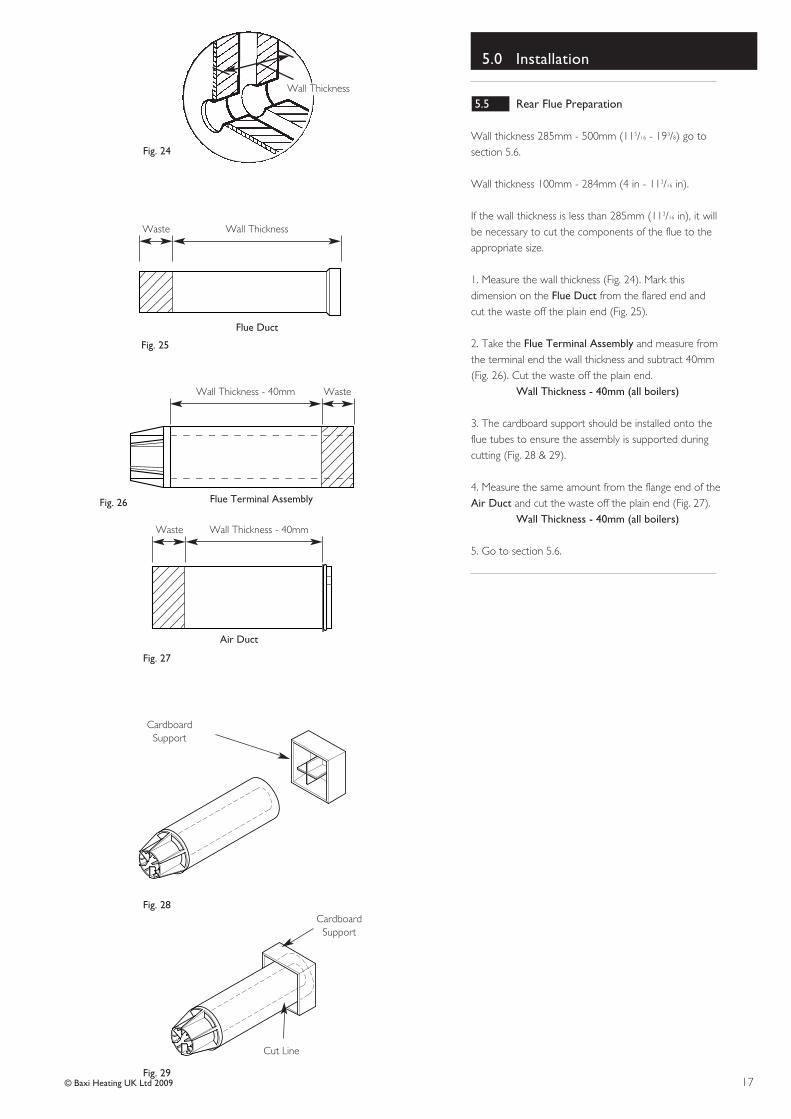
4. Take the Flue Duct and measure the dimension belowfrom the flared end. Cut the waste off the plain end (Fig.48).
Wall Thickness + X + 90mm (30, 40, 50 models) Wall Thickness + X + 145mm (60, 70, 80 models)
5. Take the Flue Terminal Assembly and measure fromthe terminal end the dimension below (Fig. 49). Cut thewaste off the plain end.
Wall Thickness + X + 50mm (30, 40, 50 models) Wall Thickness + X + 105mm (60, 70, 80 models)
6. Measure the same amount from the flange end of theAir Duct and cut the waste off the plain end (Fig. 50).
7. The cardboard support supplied in the flue pack shouldbe installed onto the flue tubes to ensure the assembly issupported during cutting (Fig. 51 & 52).
Wall Thickness + X + 90mm (30, 40, 50)Wall Thickness + X + 145mm (60, 70, 80)
WallThickness
X
Wall Thickness + X + 50mm (30, 40, 50)Wall Thickness + X + 105mm (60, 70, 80)
Wall Thickness + X + 50mm (30, 40, 50)Wall Thickness + X + 105mm (60, 70, 80)
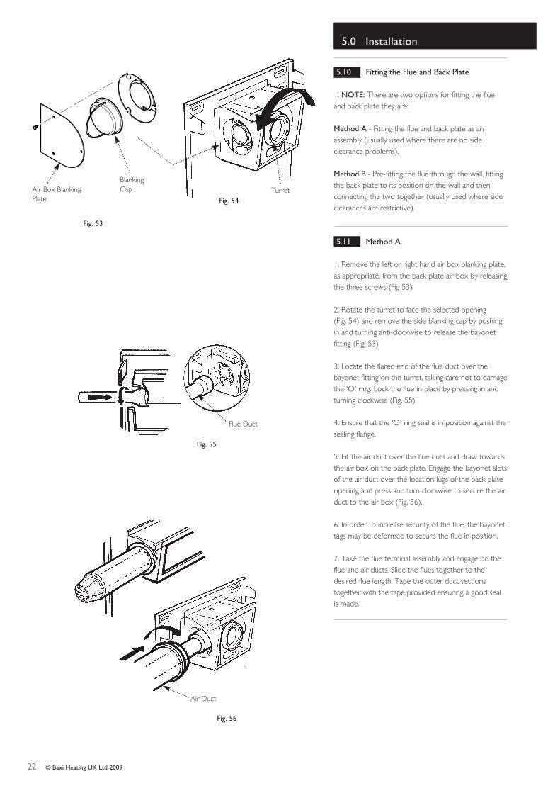
1. NOTE: There are two options for fitting the flueand back plate they are:
Method A - Fitting the flue and back plate as anassembly (usually used where there are no sideclearance problems).
Method B - Pre-fitting the flue through the wall, fittingthe back plate to its position on the wall and thenconnecting the two together (usually used where sideclearances are restrictive).
5.11 Method A
1. Remove the left or right hand air box blanking plate,as appropriate, from the back plate air box by releasingthe three screws (Fig 53).
2. Rotate the turret to face the selected opening (Fig. 54) and remove the side blanking cap by pushingin and turning anti-clockwise to release the bayonetfitting (Fig. 53).
3. Locate the flared end of the flue duct over thebayonet fitting on the turret, taking care not to damagethe 'O' ring. Lock the flue in place by pressing in andturning clockwise (Fig. 55).
4. Ensure that the 'O' ring seal is in position against thesealing flange.
5. Fit the air duct over the flue duct and draw towardsthe air box on the back plate. Engage the bayonet slotsof the air duct over the location lugs of the back plateopening and press and turn clockwise to secure the airduct to the air box (Fig. 56).
6. In order to increase security of the flue, the bayonettags may be deformed to secure the flue in position.
7. Take the flue terminal assembly and engage on theflue and air ducts. Slide the flues together to thedesired flue length. Tape the outer duct sectionstogether with the tape provided ensuring a good sealis made.
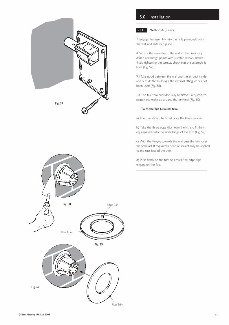
7. Engage the assembly into the hole previously cut inthe wall and slide into place.
8. Secure the assembly to the wall at the previouslydrilled anchorage points with suitable screws. Beforefinally tightening the screws, check that the assembly islevel (Fig. 57).
9. Make good between the wall and the air duct insideand outside the building if the internal fitting kit has notbeen used (Fig. 58).
10. The flue trim provided may be fitted if required, toneaten the make-up around the terminal (Fig. 60).
11. To fit the flue terminal trim:
a) The trim should be fitted once the flue is secure.
b) Take the three edge clips from the kit and fit themequi-spaced onto the inner flange of the trim (Fig. 59).
c) With the flanges towards the wall pass the trim overthe terminal. If required a bead of sealant may be appliedto the rear face of the trim.
d) Push firmly on the trim to ensure the edge clipsengage on the flue.
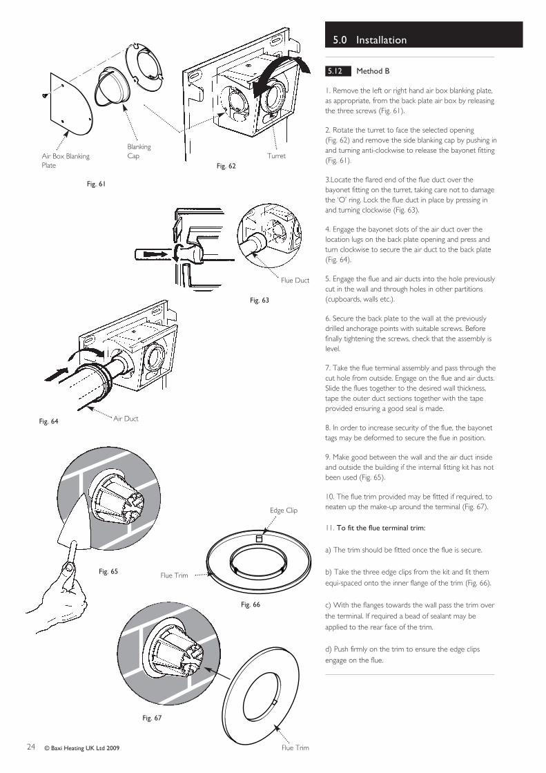
1. Remove the left or right hand air box blanking plate,as appropriate, from the back plate air box by releasingthe three screws (Fig. 61).
2. Rotate the turret to face the selected opening (Fig. 62) and remove the side blanking cap by pushing inand turning anti-clockwise to release the bayonet fitting (Fig. 61).
3.Locate the flared end of the flue duct over thebayonet fitting on the turret, taking care not to damagethe ‘O’ ring. Lock the flue duct in place by pressing inand turning clockwise (Fig. 63).
4. Engage the bayonet slots of the air duct over thelocation lugs on the back plate opening and press andturn clockwise to secure the air duct to the back plate(Fig. 64).
5. Engage the flue and air ducts into the hole previouslycut in the wall and through holes in other partitions(cupboards, walls etc.).
6. Secure the back plate to the wall at the previouslydrilled anchorage points with suitable screws. Beforefinally tightening the screws, check that the assembly islevel.
7. Take the flue terminal assembly and pass through thecut hole from outside. Engage on the flue and air ducts.Slide the flues together to the desired wall thickness,tape the outer duct sections together with the tapeprovided ensuring a good seal is made.
8. In order to increase security of the flue, the bayonettags may be deformed to secure the flue in position.
9. Make good between the wall and the air duct insideand outside the building if the internal fitting kit has notbeen used (Fig. 65).
10. The flue trim provided may be fitted if required, toneaten up the make-up around the terminal (Fig. 67).
11. To fit the flue terminal trim:
a) The trim should be fitted once the flue is secure.
b) Take the three edge clips from the kit and fit themequi-spaced onto the inner flange of the trim (Fig. 66).
c) With the flanges towards the wall pass the trim overthe terminal. If required a bead of sealant may beapplied to the rear face of the trim.
d) Push firmly on the trim to ensure the edge clipsengage on the flue.
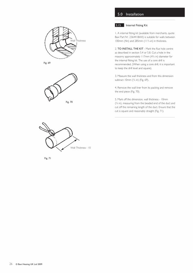
1. A internal fitting kit (available from merchants, quoteBaxi Part No. 236441BAX) is suitable for walls between100mm (4in) and 285mm (113/16in) in thickness.
2. TO INSTALL THE KIT - Mark the flue hole centreas described in section 5.4 or 5.8. Cut a hole in themasonry approximately 117mm (45/8 in) diameter forthe internal fitting kit. The use of a core drill isrecommended. (When using a core drill, it is importantto keep the drill level and square).
3. Measure the wall thickness and from this dimensionsubtract 10mm (3/8 in) (Fig. 69).
4. Remove the wall liner from its packing and removethe end piece (Fig. 70).
5. Mark off the dimension, wall thickness - 10mm (3/8 in), measuring from the beaded end of the duct andcut off the remaining length of the duct. Ensure that thecut is square and reasonably straight (Fig. 71).
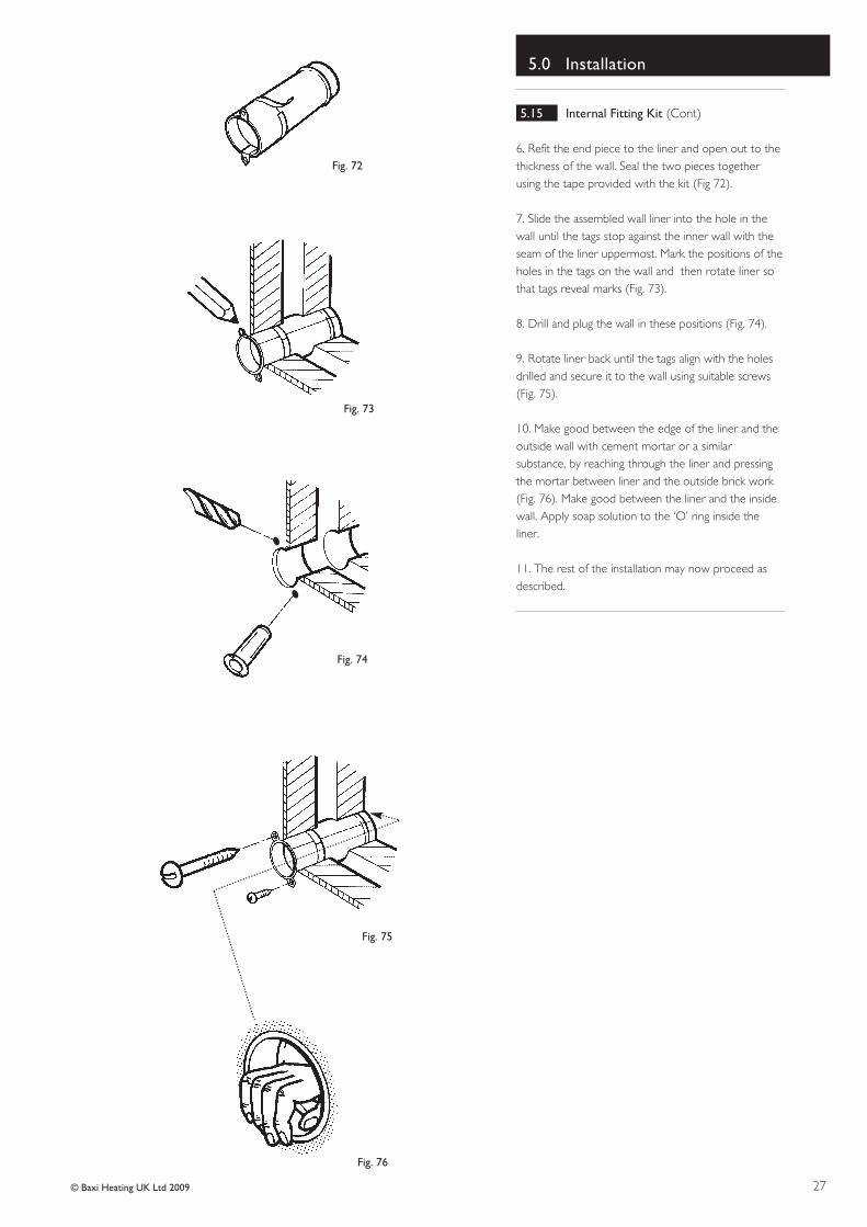
6. Refit the end piece to the liner and open out to thethickness of the wall. Seal the two pieces togetherusing the tape provided with the kit (Fig 72).
7. Slide the assembled wall liner into the hole in thewall until the tags stop against the inner wall with theseam of the liner uppermost. Mark the positions of theholes in the tags on the wall and then rotate liner sothat tags reveal marks (Fig. 73).
8. Drill and plug the wall in these positions (Fig. 74).
9. Rotate liner back until the tags align with the holesdrilled and secure it to the wall using suitable screws(Fig. 75).
10. Make good between the edge of the liner and theoutside wall with cement mortar or a similarsubstance, by reaching through the liner and pressingthe mortar between liner and the outside brick work(Fig. 76). Make good between the liner and the insidewall. Apply soap solution to the ‘O’ ring inside theliner.
11. The rest of the installation may now proceed asdescribed.
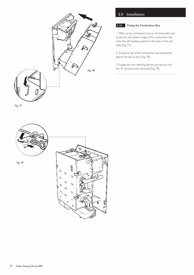
1. Offer up the combustion box to the back plate andlocate the rear bottom edge of the combustion boxonto the self locating support at the base of the wallplate (Fig. 77).
2. Swing the top of the combustion box backwardsagainst the top air box (Fig. 78).
3. Engage the two retaining latches and secure withthe 'R' clip previously removed (Fig. 79).
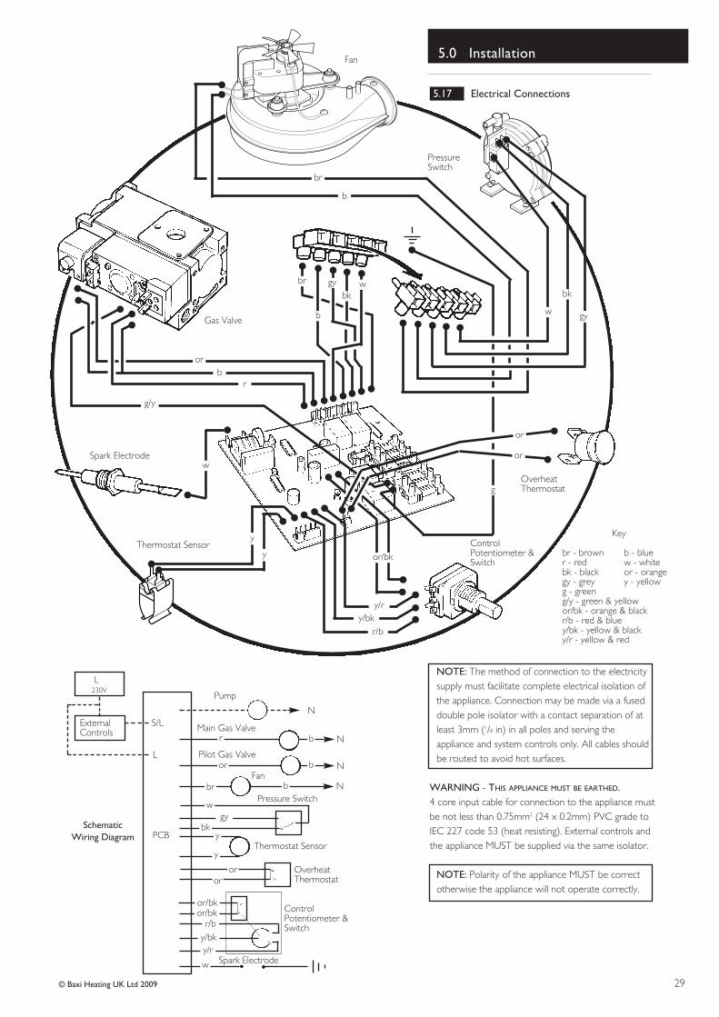
NOTE: The method of connection to the electricitysupply must facilitate complete electrical isolation ofthe appliance. Connection may be made via a fuseddouble pole isolator with a contact separation of atleast 3mm (1/8 in) in all poles and serving theappliance and system controls only. All cables shouldbe routed to avoid hot surfaces.
WARNING - THIS APPLIANCE MUST BE EARTHED.4 core input cable for connection to the appliance mustbe not less than 0.75mm2 (24 x 0.2mm) PVC grade toIEC 227 code 53 (heat resisting). External controls andthe appliance MUST be supplied via the same isolator.
NOTE: Polarity of the appliance MUST be correctotherwise the appliance will not operate correctly.
orb
r
g/y
w
br
b
gybk
w
y
y or/bk
y/ry/bk
r/b
or
or
g
w
bk
gy
br
b
Pump
N
Main Gas Valve
Pilot Gas Valve
Fan
Pressure Switch
Thermostat Sensor
OverheatThermostat
ControlPotentiometer &Switch
Spark Electrode
N
N
N
ExternalControls
S/L
L
230VL
br
bor
bbr
gyw
ybk
y
oror
or/bkor/bk
r/by/bky/r
w
PCBSchematic
Wiring Diagram
PressureSwitch
OverheatThermostat
ControlPotentiometer &Switch
Thermostat Sensor
Spark Electrode
Fan
Gas Valve
Key
br - brown b - bluer - red w - whitebk - black or - orangegy - grey y - yellowg - greeng/y - green & yellowor/bk - orange & blackr/b - red & bluey/bk - yellow & blacky/r - yellow & red
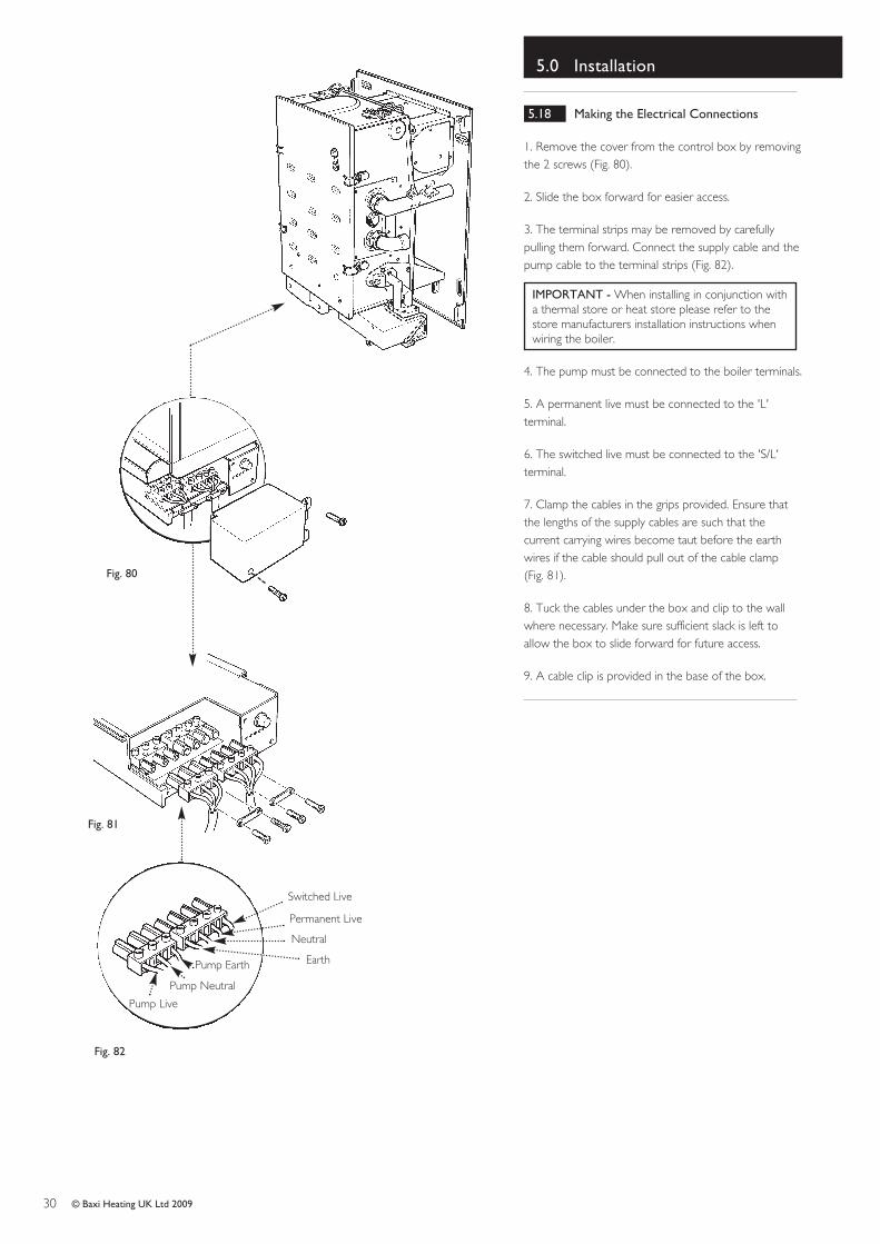
1. Remove the cover from the control box by removingthe 2 screws (Fig. 80).
2. Slide the box forward for easier access.
3. The terminal strips may be removed by carefullypulling them forward. Connect the supply cable and thepump cable to the terminal strips (Fig. 82).
IMPORTANT - When installing in conjunction witha thermal store or heat store please refer to thestore manufacturers installation instructions whenwiring the boiler.
4. The pump must be connected to the boiler terminals.
5. A permanent live must be connected to the 'L'terminal.
6. The switched live must be connected to the 'S/L'terminal.
7. Clamp the cables in the grips provided. Ensure thatthe lengths of the supply cables are such that thecurrent carrying wires become taut before the earthwires if the cable should pull out of the cable clamp (Fig. 81).
8. Tuck the cables under the box and clip to the wallwhere necessary. Make sure sufficient slack is left toallow the box to slide forward for future access.
9. A cable clip is provided in the base of the box.
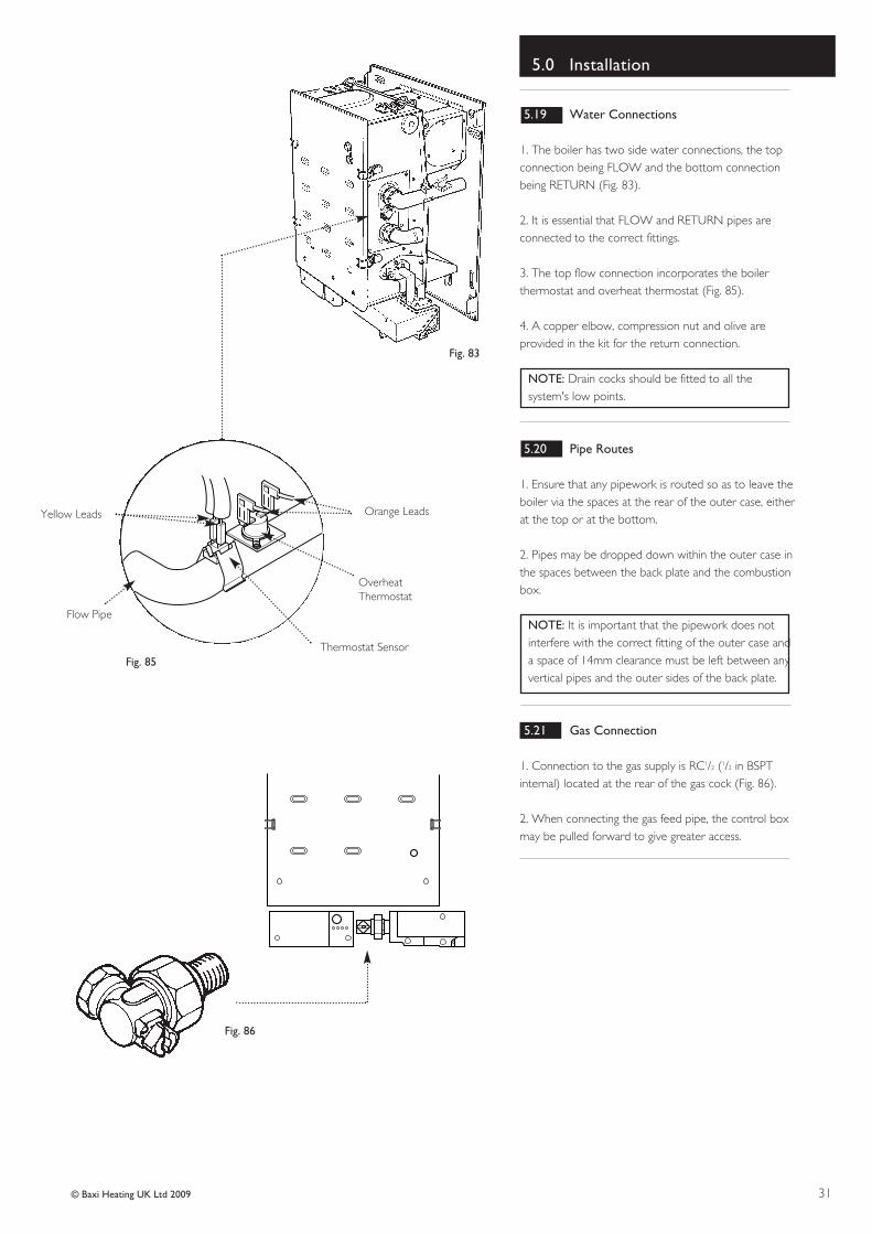
1. The boiler has two side water connections, the topconnection being FLOW and the bottom connectionbeing RETURN (Fig. 83).
2. It is essential that FLOW and RETURN pipes areconnected to the correct fittings.
3. The top flow connection incorporates the boilerthermostat and overheat thermostat (Fig. 85).
4. A copper elbow, compression nut and olive areprovided in the kit for the return connection.
NOTE: Drain cocks should be fitted to all thesystem's low points.
5.20 Pipe Routes
1. Ensure that any pipework is routed so as to leave theboiler via the spaces at the rear of the outer case, eitherat the top or at the bottom.
2. Pipes may be dropped down within the outer case inthe spaces between the back plate and the combustionbox.
NOTE: It is important that the pipework does notinterfere with the correct fitting of the outer case anda space of 14mm clearance must be left between anyvertical pipes and the outer sides of the back plate.
5.21 Gas Connection
1. Connection to the gas supply is RC1/2 (1/2 in BSPTinternal) located at the rear of the gas cock (Fig. 86).
2. When connecting the gas feed pipe, the control boxmay be pulled forward to give greater access.
1. The system must be flushed in accordance with BS7593 (see Section 3.1 Water Circulating Systems) andthe flushing agent manufacturers instructions, furtherguidance can be obtained from BS 5449 section 5.
2. At the time of commissioning, complete all relevantsections of the Benchmark Checklist at the rear of thispublications.
3. Turn the gas supply on and purge according toin GB BS 6891 and in IE the current edition of I.S. 813
“Domestic Gas Installations”.
4. Ensure that the electrical supply is isolated.
5. Check the electrical supply for earth continuity,polarity, short circuit and resistance to earth.
6. Turn the gas service cock anti-clockwise to the ONposition and check for gas soundness up to the gasvalve.
7. Loosen the pressure test point screw on the righthand side of the gas control valve (there is no need tocompletely remove this screw to obtain a pressurereading) and connect a pressure gauge.
8. Turn the boiler thermostat control knob fully anti-clockwise to the OFF position marked 0 (Fig. 88).
9. Ensure that the electricity supply is turned ON andset any external controls to the ON position.
10. Turn the boiler thermostat knob fully clockwise.
11. The fan will start running and after approximately 10seconds, the ignition spark will commence.
12. The sparking will continue until the pilot light isestablished (Fig. 89) and then the main burner will lightfrom the pilot flame.
13. Check that both the main burner and the pilot arealight by observing through the viewing window. Theindicator lights should also be illuminated.
14. Should this sequence not occur, then refer to thefault finding section of these instructions.
NOTE: The pilot rate for this appliance is factoryset, sealed and therefore non-adjustable.
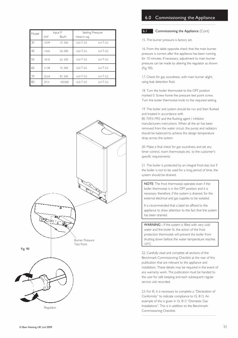
16. From the table opposite check that the main burnerpressure is correct after the appliance has been runningfor 10 minutes. If necessary, adjustment to main burnerpressure can be made by altering the regulator as shown(Fig. 90).
17. Check for gas soundness, with main burner alight,using leak detection fluid.
18. Turn the boiler thermostat to the OFF positionmarked 0. Screw home the pressure test point screw.Turn the boiler thermostat knob to the required setting.
19. The boiler and system should be run and then flushedand treated in accordance with BS 7593:1992 and the flushing agent / inhibitormanufacturers instructions. When all the air has beenremoved from the water circuit, the pump and radiatorsshould be balanced to achieve the design temperaturedrop across the system.
20. Make a final check for gas soundness and set anytimer control, room thermostats etc. to the customer'sspecific requirements.
21. The boiler is protected by an integral frost-stat, but ifthe boiler is not to be used for a long period of time, thesystem should be drained.
NOTE: The frost thermostat operates even if theboiler thermostat is in the OFF position and it isnecessary therefore, if the system is drained, for theexternal electrical and gas supplies to be isolated.
It is recommended that a label be affixed to theappliance to draw attention to the fact that the systemhas been drained.
WARNING - If the system is filled with very coldwater and the boiler lit, the action of the frostprotection thermostat will prevent the boiler fromshutting down before the water temperature reaches10°C.
22. Carefully read and complete all sections of theBenchmark Commissioning Checklist at the rear of thispublication that are relevant to the appliance andinstallation. These details may be required in the event ofany warranty work. The publication must be handed tothe user for safe keeping and each subsequent regularservice visit recorded.
23. For IE, it is necessary to complete a “Declaration ofConformity” to indicate compliance to I.S. 813. Anexample of this is given in I.S. 813 “Domestic GasInstallations”. This is in addition to the BenchmarkCommissioning Checklist.
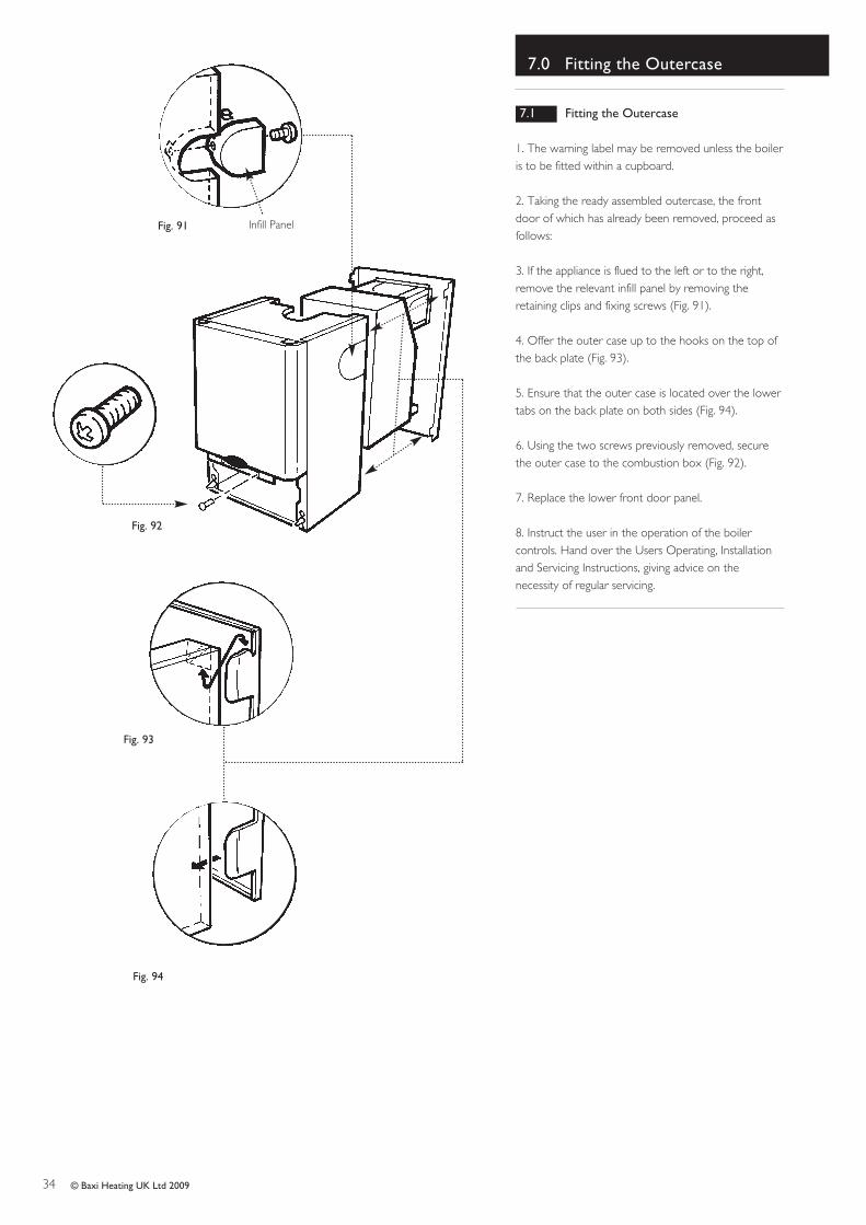
1. The warning label may be removed unless the boileris to be fitted within a cupboard.
2. Taking the ready assembled outercase, the frontdoor of which has already been removed, proceed asfollows:
3. If the appliance is flued to the left or to the right,remove the relevant infill panel by removing theretaining clips and fixing screws (Fig. 91).
4. Offer the outer case up to the hooks on the top ofthe back plate (Fig. 93).
5. Ensure that the outer case is located over the lowertabs on the back plate on both sides (Fig. 94).
6. Using the two screws previously removed, securethe outer case to the combustion box (Fig. 92).
7. Replace the lower front door panel.
8. Instruct the user in the operation of the boilercontrols. Hand over the Users Operating, Installationand Servicing Instructions, giving advice on thenecessity of regular servicing.
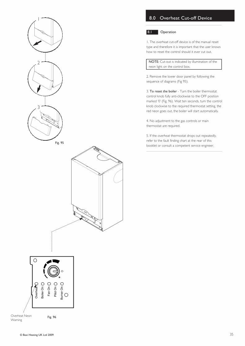
1. The overheat cut-off device is of the manual resettype and therefore it is important that the user knowshow to reset the control should it ever cut out.
NOTE: Cut-out is indicated by illumination of theneon light on the control box.
2. Remove the lower door panel by following thesequence of diagrams (Fig 95).
3. To reset the boiler - Turn the boiler thermostatcontrol knob fully anti-clockwise to the OFF positionmarked ‘0’ (Fig. 96). Wait ten seconds, turn the controlknob clockwise to the required thermostat setting, thered neon goes out, the boiler will start automatically.
4. No adjustment to the gas controls or mainthermostat are required.
5. If the overheat thermostat drops out repeatedly,refer to the fault finding chart at the rear of thisbooklet or consult a competent service engineer.
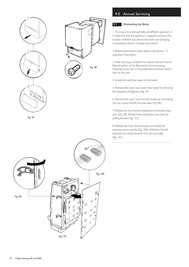
1. To ensure its continued safe and efficient operation, itis important that the appliance is regularly serviced. (Forlocation of British Gas service test point see ChangingComponents section of these instructions).
2. Before servicing the boiler please read Section 1.3Important Information.
3. After servicing, complete the relevant Service IntervalRecord section of the Benchmark CommissioningChecklist at the rear of this publication and then hand itback to the user.
4. Isolate the electrical supply to the boiler.
5. Remove the outer case lower door panel by followingthe sequence of diagrams (Fig. 97).
6. Remove the outer case from the boiler by unscrewingthe two screws and lift the case clear (Fig. 98).
7. Release the four latches holding the combustion boxdoor (Fig. 99). Remove the combustion box door bypulling forward (Fig. 101).
8. Release the 5-pin electrical plug connecting thepressure switch and fan (Fig. 100). Withdraw the fanassembly by pulling forwards from the top edge (Fig. 101).
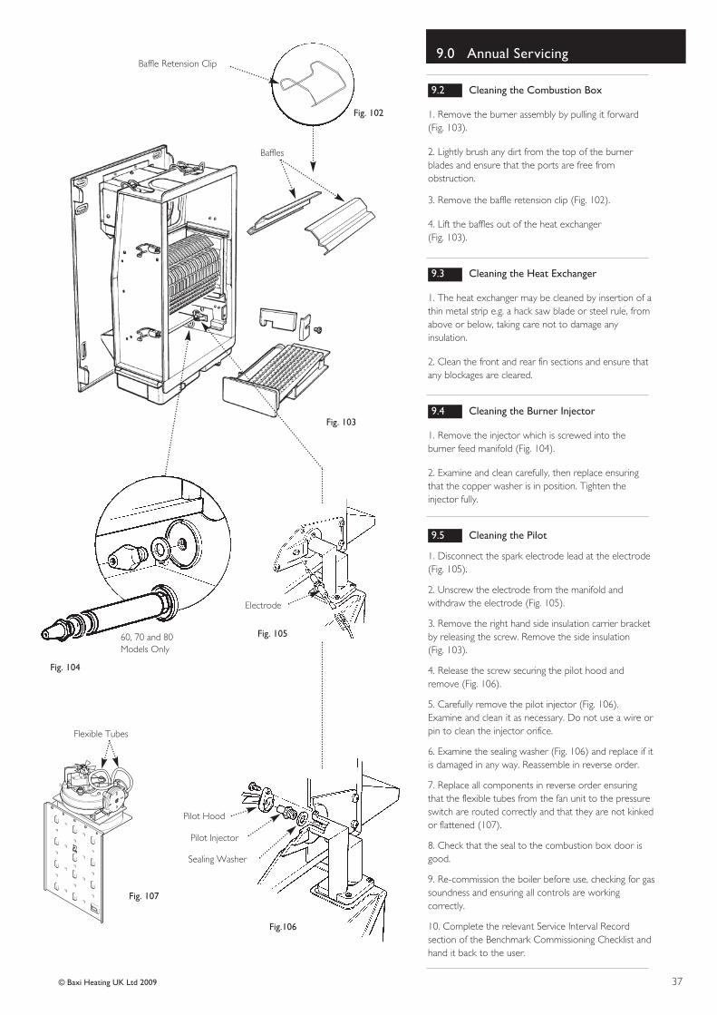
1. Remove the burner assembly by pulling it forward(Fig. 103).
2. Lightly brush any dirt from the top of the burnerblades and ensure that the ports are free fromobstruction.
3. Remove the baffle retension clip (Fig. 102).
4. Lift the baffles out of the heat exchanger (Fig. 103).
9.3 Cleaning the Heat Exchanger
1. The heat exchanger may be cleaned by insertion of athin metal strip e.g. a hack saw blade or steel rule, fromabove or below, taking care not to damage anyinsulation.
2. Clean the front and rear fin sections and ensure thatany blockages are cleared.
9.4 Cleaning the Burner Injector
1. Remove the injector which is screwed into theburner feed manifold (Fig. 104).
2. Examine and clean carefully, then replace ensuringthat the copper washer is in position. Tighten theinjector fully.
9.5 Cleaning the Pilot
1. Disconnect the spark electrode lead at the electrode(Fig. 105).
2. Unscrew the electrode from the manifold andwithdraw the electrode (Fig. 105).
3. Remove the right hand side insulation carrier bracketby releasing the screw. Remove the side insulation (Fig. 103).
4. Release the screw securing the pilot hood andremove (Fig. 106).
5. Carefully remove the pilot injector (Fig. 106).Examine and clean it as necessary. Do not use a wire orpin to clean the injector orifice.
6. Examine the sealing washer (Fig. 106) and replace if itis damaged in any way. Reassemble in reverse order.
7. Replace all components in reverse order ensuringthat the flexible tubes from the fan unit to the pressureswitch are routed correctly and that they are not kinkedor flattened (107).
8. Check that the seal to the combustion box door isgood.
9. Re-commission the boiler before use, checking for gassoundness and ensuring all controls are workingcorrectly.
10. Complete the relevant Service Interval Recordsection of the Benchmark Commissioning Checklist andhand it back to the user.
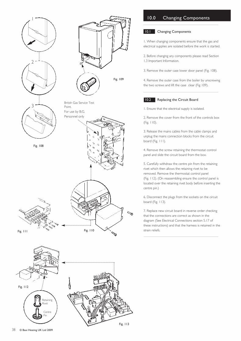
1. When changing components ensure that the gas andelectrical supplies are isolated before the work is started.
2. Before changing any components please read Section1.3 Important Information.
3. Remove the outer case lower door panel (Fig. 108).
4. Remove the outer case from the boiler by unscrewingthe two screws and lift the case clear (Fig 109).
10.2 Replacing the Circuit Board
1. Ensure that the electrical supply is isolated.
2. Remove the cover from the front of the controls box(Fig. 110).
3. Release the mains cables from the cable clamps andunplug the mains connection blocks from the circuitboard (Fig. 111).
4. Remove the screw retaining the thermostat controlpanel and slide the circuit board from the box.
5. Carefully withdraw the centre pin from the retainingrivet which then allows the retaining rivet to beremoved. Remove the thermostat control panel (Fig. 112). (On reassembling ensure the control panel islocated over the retaining rivet body before inserting thecentre pin.)
6. Disconnect the plugs from the sockets on the circuitboard (Fig. 113).
7. Replace new circuit board in reverse order checkingthat the connections are correct as shown in thediagram (See Electrical Connections section 5.17 ofthese instructions) and that the harness is retained in thestrain reliefs.
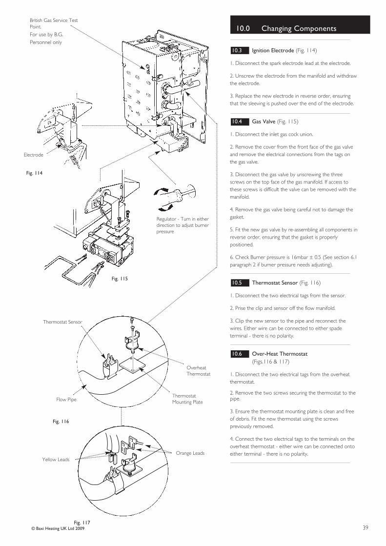
1. Disconnect the spark electrode lead at the electrode.
2. Unscrew the electrode from the manifold and withdrawthe electrode.
3. Replace the new electrode in reverse order, ensuringthat the sleeving is pushed over the end of the electrode.
10.4 Gas Valve (Fig. 115)
1. Disconnect the inlet gas cock union.
2. Remove the cover from the front face of the gas valveand remove the electrical connections from the tags onthe gas valve.
3. Disconnect the gas valve by unscrewing the threescrews on the top face of the gas manifold. If access tothese screws is difficult the valve can be removed with themanifold.
4. Remove the gas valve being careful not to damage thegasket.
5. Fit the new gas valve by re-assembling all components inreverse order, ensuring that the gasket is properlypositioned.
6. Check Burner pressure is 16mbar ± 0.5 (See section 6.1paragraph 2 if burner pressure needs adjusting).
10.5 Thermostat Sensor (Fig. 116)
1. Disconnect the two electrical tags from the sensor.
2. Prise the clip and sensor off the flow manifold.
3. Clip the new sensor to the pipe and reconnect thewires. Either wire can be connected to either spadeterminal - there is no polarity.
10.6 Over-Heat Thermostat (Figs.116 & 117)
1. Disconnect the two electrical tags from the overheatthermostat.
2. Remove the two screws securing the thermostat to thepipe.
3. Ensure the thermostat mounting plate is clean and freeof debris. Fit the new thermostat using the screwspreviously removed.
4. Connect the two electrical tags to the terminals on theoverheat thermostat - either wire can be connected ontoeither terminal - there is no polarity.
Fig. 114
Fig. 115
Electrode
Fig. 116
Fig. 117
OverheatThermostat
Flow Pipe
Thermostat Sensor
Orange LeadsYellow Leads
British Gas Service TestPoint.
For use by B.G.Personnel only
Regulator - Turn in eitherdirection to adjust burnerpressure
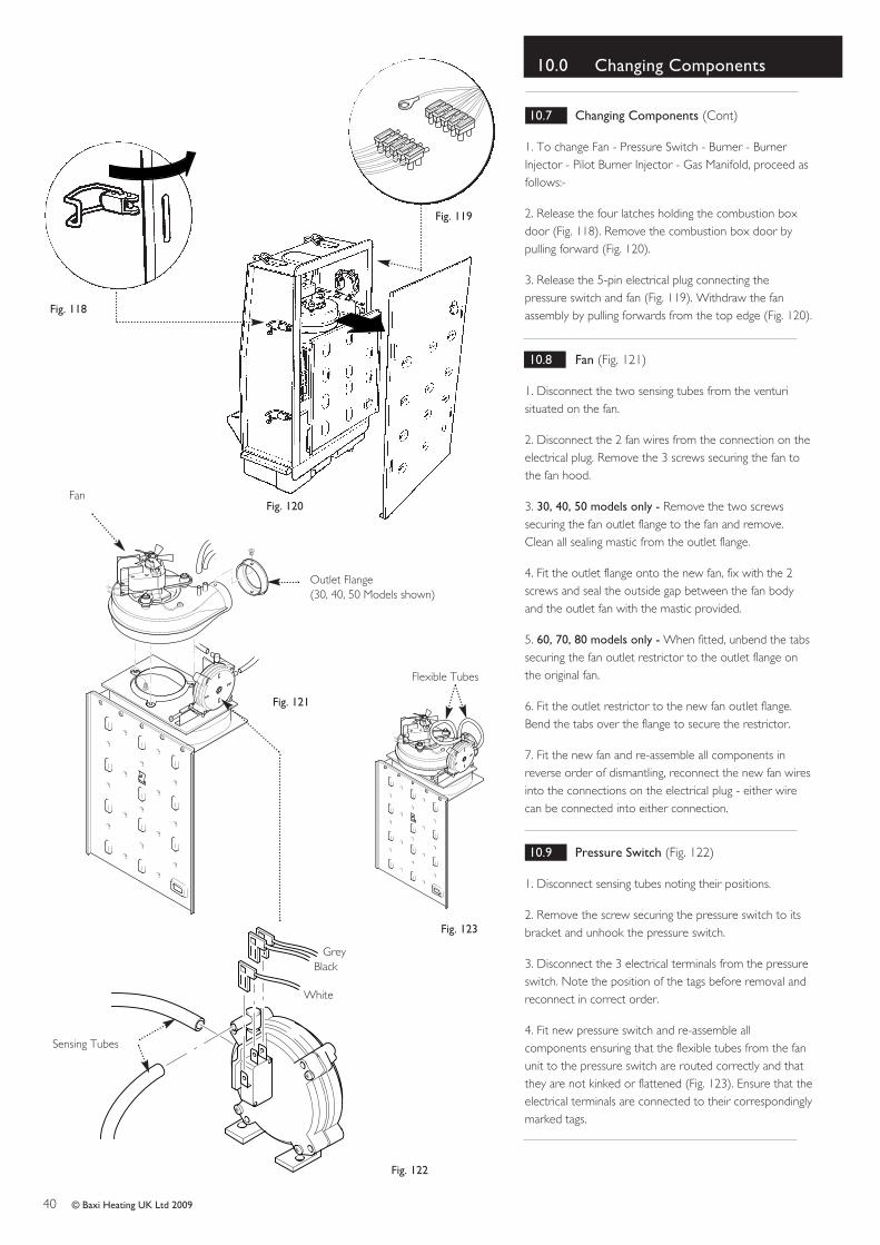
1. To change Fan - Pressure Switch - Burner - BurnerInjector - Pilot Burner Injector - Gas Manifold, proceed asfollows:-
2. Release the four latches holding the combustion boxdoor (Fig. 118). Remove the combustion box door bypulling forward (Fig. 120).
3. Release the 5-pin electrical plug connecting thepressure switch and fan (Fig. 119). Withdraw the fanassembly by pulling forwards from the top edge (Fig. 120).
10.8 Fan (Fig. 121)
1. Disconnect the two sensing tubes from the venturisituated on the fan.
2. Disconnect the 2 fan wires from the connection on theelectrical plug. Remove the 3 screws securing the fan tothe fan hood.
3. 30, 40, 50 models only - Remove the two screwssecuring the fan outlet flange to the fan and remove.Clean all sealing mastic from the outlet flange.
4. Fit the outlet flange onto the new fan, fix with the 2screws and seal the outside gap between the fan bodyand the outlet fan with the mastic provided.
5. 60, 70, 80 models only - When fitted, unbend the tabssecuring the fan outlet restrictor to the outlet flange onthe original fan.
6. Fit the outlet restrictor to the new fan outlet flange.Bend the tabs over the flange to secure the restrictor.
7. Fit the new fan and re-assemble all components inreverse order of dismantling, reconnect the new fan wiresinto the connections on the electrical plug - either wirecan be connected into either connection.
10.9 Pressure Switch (Fig. 122)
1. Disconnect sensing tubes noting their positions.
2. Remove the screw securing the pressure switch to itsbracket and unhook the pressure switch.
3. Disconnect the 3 electrical terminals from the pressureswitch. Note the position of the tags before removal andreconnect in correct order.
4. Fit new pressure switch and re-assemble allcomponents ensuring that the flexible tubes from the fanunit to the pressure switch are routed correctly and thatthey are not kinked or flattened (Fig. 123). Ensure that theelectrical terminals are connected to their correspondinglymarked tags.
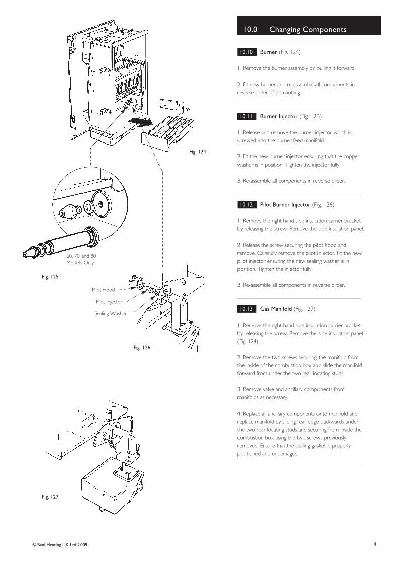
1. Remove the burner assembly by pulling it forward.
2. Fit new burner and re-assemble all components inreverse order of dismantling.
10.11 Burner Injector (Fig. 125)
1. Release and remove the burner injector which isscrewed into the burner feed manifold.
2. Fit the new burner injector ensuring that the copperwasher is in position. Tighten the injector fully.
3. Re-assemble all components in reverse order.
10.12 Pilot Burner Injector (Fig. 126)
1. Remove the right hand side insulation carrier bracketby releasing the screw. Remove the side insulation panel.
2. Release the screw securing the pilot hood andremove. Carefully remove the pilot injector. Fit the newpilot injector ensuring the new sealing washer is inposition. Tighten the injector fully.
3. Re-assemble all components in reverse order.
10.13 Gas Manifold (Fig. 127)
1. Remove the right hand side insulation carrier bracketby releasing the screw. Remove the side insulation panel(Fig. 124).
2. Remove the two screws securing the manifold fromthe inside of the combustion box and slide the manifoldforward from under the two rear locating studs.
3. Remove valve and ancillary components frommanifolds as necessary.
4. Replace all ancillary components onto manifold andreplace manifold by sliding rear edge backwards underthe two rear locating studs and securing from inside thecombustion box using the two screws previouslyremoved. Ensure that the sealing gasket is properlypositioned and undamaged.
Check the pilot injector is notblocked, partially blocked or
damaged
Check there is 20mbar gas pressure at
the inlet to gas valve
Isthere the
correct burner pressureat the test point ?
YES YES
YES
YES
YES
NO NO
NO
NO
NO
Check pilot injector isnot blocked
Check main injectoris not blocked
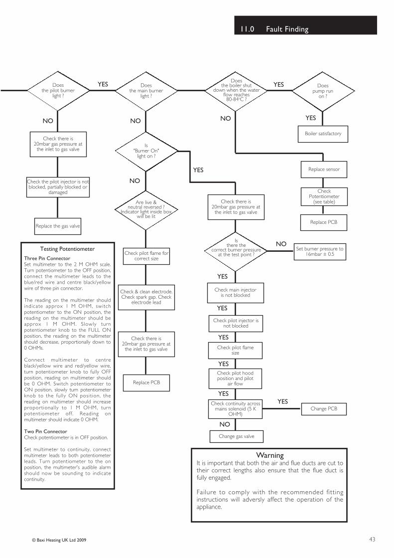
WarningIt is important that both the air and flue ducts are cut totheir correct lengths also ensure that the flue duct isfully engaged.
Failure to comply with the recommended fittinginstructions will adversly affect the operation of theappliance.
Check pilot flame size
YES
YES
YES
YES
Check pilot hoodposition and pilot
air flow
Check continuity acrossmains solenoid (5 K
OHM)
Change gas valve
NO
Change PCBYES
Testing Potentiometer
Three Pin ConnectorSet multimeter to the 2 M OHM scale.Turn potentiometer to the OFF position,connect the multimeter leads to theblue/red wire and centre black/yellowwire of three pin connector.
The reading on the multimeter shouldindicate approx 1 M OHM, switchpotentiometer to the ON position, thereading on the multimeter should beapprox 1 M OHM. Slowly turnpotentiometer knob to the FULL ONposition, the reading on the multimetershould decrease, proportionally down to0 OHMs.
Connect multimeter to centreblack/yellow wire and red/yellow wire,turn potentiometer knob to fully OFFposition, reading on multimeter shouldbe 0 OHM. Switch potentiometer toON position, slowly turn potentiometerknob to the ful ly ON position, thereading on multimeter should increaseproportionally to 1 M OHM, turnpotentiometer off . Reading onmultimeter should indicate 0 OHM.
Two Pin ConnectorCheck potentiometer is in OFF position.
Set multimeter to continuity, connectmultimeter leads to both potentiometerleads. Turn potentiometer to the onposition, the multimeter's audible alarmshould now be sounding to indicatecontinuity.
Time and Temperature Control to Heating Room Thermostat and Programmable Load/Weather Optimum Start remiT/remmargorP Room Thermostat Compensation Control
remiT/remmargorP dna tatsomrehT rednilyC retaW toH ot lortnoC erutarepmeT dna emiT Combination Boiler
dettiF sevlaV enoZ gnitaeH Not Required
dettiF sevlaV enoZ retaW toH Not Required
dettiF sevlaV rotaidaR citatsomrehT Not Required
dettiF metsyS ot ssapyB citamotuA Not Required
dedivorP kcolretnI relioB
ALL SYSTEMS
The system has been fl seY snoitcurtsni s’rerutcafunam reliob dna 3957SB htiw ecnadrocca ni denaelc dna dehsu
What system cleaner was used?
What inhibitor was used? Quantity litres
CENTRAL HEATING MODE Measure and Record:
Gas Rate m3/hr OR ft3/hr
)elbacilppa fi( erusserP gnitarepO renruB mbar OR Gas Inlet Pressure mbar
Central Heating Flow Temperature °C
Central Heating Return Temperature °C
COMBINATION BOILERS ONLY
Is the installation in a hard water area (above 200ppm)? Yes No
If yes, has a water scale reducer been fi tted? Yes No
seY snoitcurtsni s’rerutcafunam eht htiw ecnadrocca ni denoissimmoc dna dellatsni neeb evah stcudorp detaicossa dna reliob ehT
seY remotsuc eht yb dootsrednu dna ot detartsnomed neeb evah slortnoc metsys dna reliob eht fo noitarepo ehT
The manufacturer’s literature, including Benchmark Checklist and Service Record, has been explained and left with the customer Yes
*All installations in England and Wales must be notifi ed to Local Authority Building Control (LABC) either directly or through a Competent Persons Scheme. A Building Regulations Compliance Certifi cate will then be issued to the customer.
Customer’s Signature(To confi rm satisfactory demonstration and receipt of manufacturer’s literature)
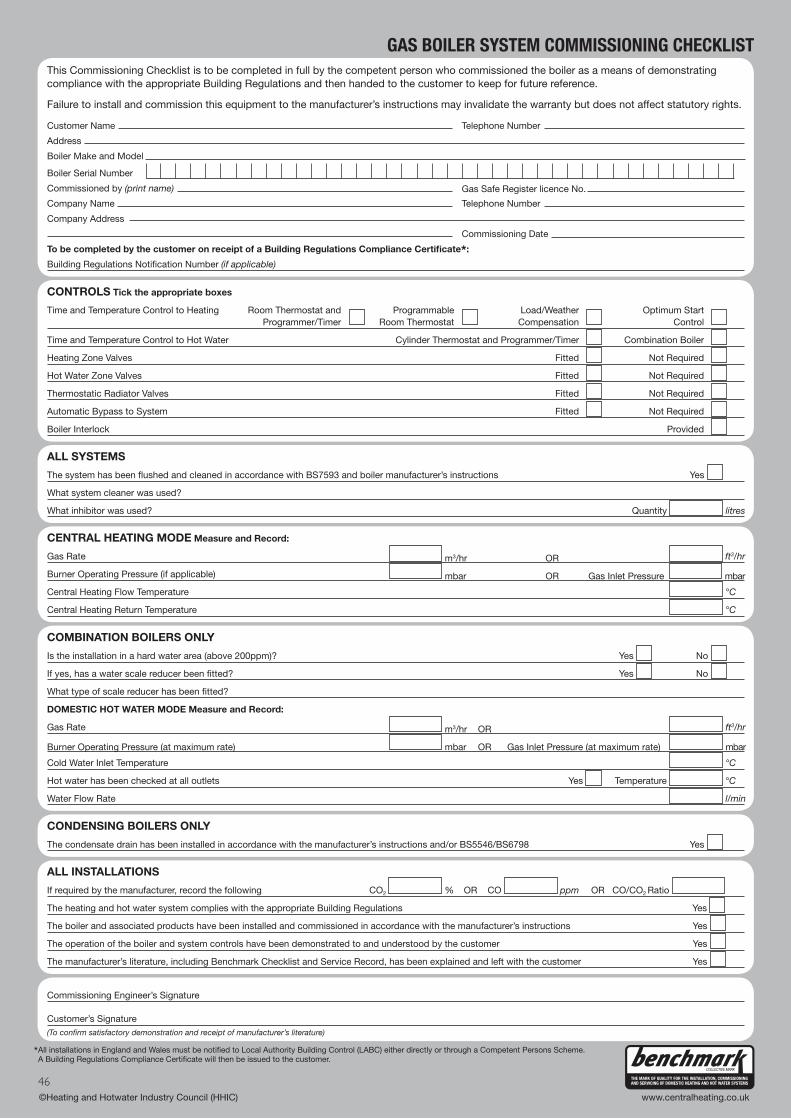
This Commissioning Checklist is to be completed in full by the competent person who commissioned the boiler as a means of demonstratingcompliance with the appropriate Building Regulations and then handed to the customer to keep for future reference.
Failure to install and commission this equipment to the manufacturer’s instructions may invalidate the warranty but does not affect statutory rights.
Customer Name Telephone Number
Address
Boiler Make and Model
Boiler Serial Number
Commissioned by (print name)
Company Name Telephone Number
Gas Safe Register licence No.
Company Address
Commissioning Date
To be completed by the customer on receipt of a Building Regulations Compliance Certifi cate*:
Building Regulations Notifi cation Number (if applicable)
SERVICE RECORDIt is recommended that your heating system is serviced regularly and that the appropriate Service Record is completed.
Service ProviderBefore completing the appropriate Service Record below, please ensure you have carried out the service as described in the manufacturer’s instructions.
Always use the manufacturer’s specifi ed spare part when replacing controls.
SERVICE 1 Date
Energy Effi ciency Checklist completed? Yes No
Engineer Name
Company Name
Telephone Number
Comments
Signature
SERVICE 3 Date
Energy Effi ciency Checklist completed? Yes No
Engineer Name
Company Name
Telephone Number
Comments
Signature
SERVICE 5 Date
Energy Effi ciency Checklist completed? Yes No
Engineer Name
Company Name
Telephone Number
Comments
Signature
SERVICE 7 Date
Energy Effi ciency Checklist completed? Yes No
Engineer Name
Company Name
Telephone Number
Comments
Signature
SERVICE 9 Date
Energy Effi ciency Checklist completed? Yes No
Engineer Name
Company Name
Telephone Number
Comments
Signature
SERVICE 2 Date
Energy Effi ciency Checklist completed? Yes No
Engineer Name
Company Name
Telephone Number
Comments
Signature
SERVICE 4 Date
Energy Effi ciency Checklist completed? Yes No
Engineer Name
Company Name
Telephone Number
Comments
Signature
SERVICE 6 Date
Energy Effi ciency Checklist completed? Yes No
Engineer Name
Company Name
Telephone Number
Comments
Signature
SERVICE 8 Date
Energy Effi ciency Checklist completed? Yes No
Engineer Name
Company Name
Telephone Number
Comments
Signature
SERVICE 10 Date
Energy Effi ciency Checklist completed? Yes No
Engineer Name
Company Name
Telephone Number
Comments
Signature
Gas Safe Register licence No. Gas Safe Register licence No.
Gas Safe Register licence No. Gas Safe Register licence No.
Gas Safe Register licence No. Gas Safe Register licence No.
Gas Safe Register licence No. Gas Safe Register licence No.
Gas Safe Register licence No. Gas Safe Register licence No.