15
CAMPAGNOLO.COM BB CUPS PRO-TECH ™ ULTRA-TORQUE ™ POWER-TORQUE ™ POWER-TORQUE+ ™

C A M PA G N O L O . C O M
B B C U P SP R O - T E C H ™
U LT R A - TO R Q U E ™
P OW E R - TO R Q U E ™
P OW E R - TO R Q U E + ™
B B C U P S - R ev. 0 3 / 0 3 - 2 0 2 1 C A M PA G N O L O C O M P O N E N T S - T E C H N I C A L M A N UA L2
ALWAYS wear protective gloves and glasses while working on the bicycle.
WARNING!
B B C U P S - R ev. 0 3 / 0 3 - 2 0 2 1 C A M PA G N O L O C O M P O N E N T S - T E C H N I C A L M A N UA L3
B B C U P S
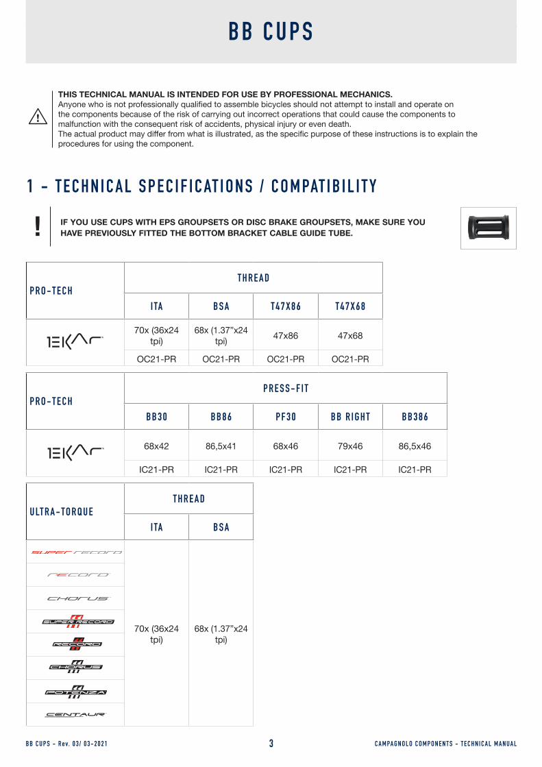
1 - T E C H N I C A L S P E C I F I C AT I O N S / C O M PAT I B I L I T Y
THIS TECHNICAL MANUAL IS INTENDED FOR USE BY PROFESSIONAL MECHANICS.Anyone who is not professionally qualified to assemble bicycles should not attempt to install and operate on the components because of the risk of carrying out incorrect operations that could cause the components to malfunction with the consequent risk of accidents, physical injury or even death.The actual product may differ from what is illustrated, as the specific purpose of these instructions is to explain the procedures for using the component.
IF YOU USE CUPS WITH EPS GROUPSETS OR DISC BRAKE GROUPSETS, MAKE SURE YOU HAVE PREVIOUSLY FITTED THE BOTTOM BRACKET CABLE GUIDE TUBE.!
P R O - T E C HT H R E A D
I TA B S A T 4 7 X 8 6 T 4 7 X 6 8
70x (36x24 tpi)
68x (1.37”x24 tpi) 47x86 47x68
OC21-PR OC21-PR OC21-PR OC21-PR
P R O - T E C HP R E S S - F I T
B B 3 0 B B 8 6 P F 3 0 B B R I G H T B B 3 8 6
68x42 86,5x41 68x46 79x46 86,5x46
IC21-PR IC21-PR IC21-PR IC21-PR IC21-PR
U LT R A - TO R Q U ET H R E A D
I TA B S A
70x (36x24 tpi)
68x (1.37”x24 tpi)

B B C U P S - R ev. 0 3 / 0 3 - 2 0 2 1 C A M PA G N O L O C O M P O N E N T S - T E C H N I C A L M A N UA L4
P OW E R - TO R Q U EP OW E R - TO R Q U E +
T H R E A D
I TA B S A
70x (36x24 tpi)
68x (1.37”x24 tpi)
P OW E R - TO R Q U EP OW E R - TO R Q U E +
P R E S S - F I T
B B 3 0 B B 8 6 P F 3 0 B B 3 0 A B B 3 8 6
68x42 86,5x41 68x46 73x42 86,5x46
U LT R A - TO R Q U EP R E S S - F I T
B B 3 0 B B 3 0 A B B 8 6 P F 3 0 B B R I G H T B B 3 8 6
68x42 73x42 86,5x41 68x46 79x46 86,5x46
Combinations other than those in the tables could cause the drivetrain to malfunction and result in accidents, physical injury or death.
WARNING!

C A M PA G N O L O C O M P O N E N T S - T E C H N I C A L M A N UA L5
2 - I N T E R FA C E W I T H F R A M E
B B C U P S - R ev. 0 3 / 0 3 - 2 0 2 1
2 . 1 - C O M PAT I B I L I T Y W I T H B OT TO M B R A C K E T S H E L L S - S TA N DA R D V E R S I O N
When installing a crankset on a frame, the bottom bracket shell must comply with the tolerances specified. If the mating tolerances comply with specifications, correct operation is ensured by the matching dimensions.
The Campagnolo Ultra-Torque / Power-Torque system crankset is compatible with bottom bracket shells that have the following widths:
TYPE
X
max 0,5 x 45
max 0,5 x 45
4141
L = 86,5
Tratto a min. L = 10,541
Zona tratto in tolleranza min. L = 5
Tratto a min. L = 10,541
Zona tratto in tolleranza min. L = 5
L = 86,5 ± 0,5
Min. length of the Ø 41 section = 10,5Min. length of the Ø 41 section = 10,5
Min. tolerance area of the section = 5 Min. tolerance area of the section = 5
Ø 41
- 0,03
- 0,06Ø
41 - 0,03
- 0,06
max 0,5 x 45
max 0,5 x 45
Important: where not specified, all measurements are expressed in millimetres.
Fig.1
2 . 2 - B OT TO M B R A C K E T S H E L L B B 8 6 L = 8 6 . 5 m m X Ø 4 1 m m
Fig.2
C A M PA G N O L O C O M P O N E N T S - T E C H N I C A L M A N UA L6B B C U P S - R ev. 0 3 / 0 3 - 2 0 2 1
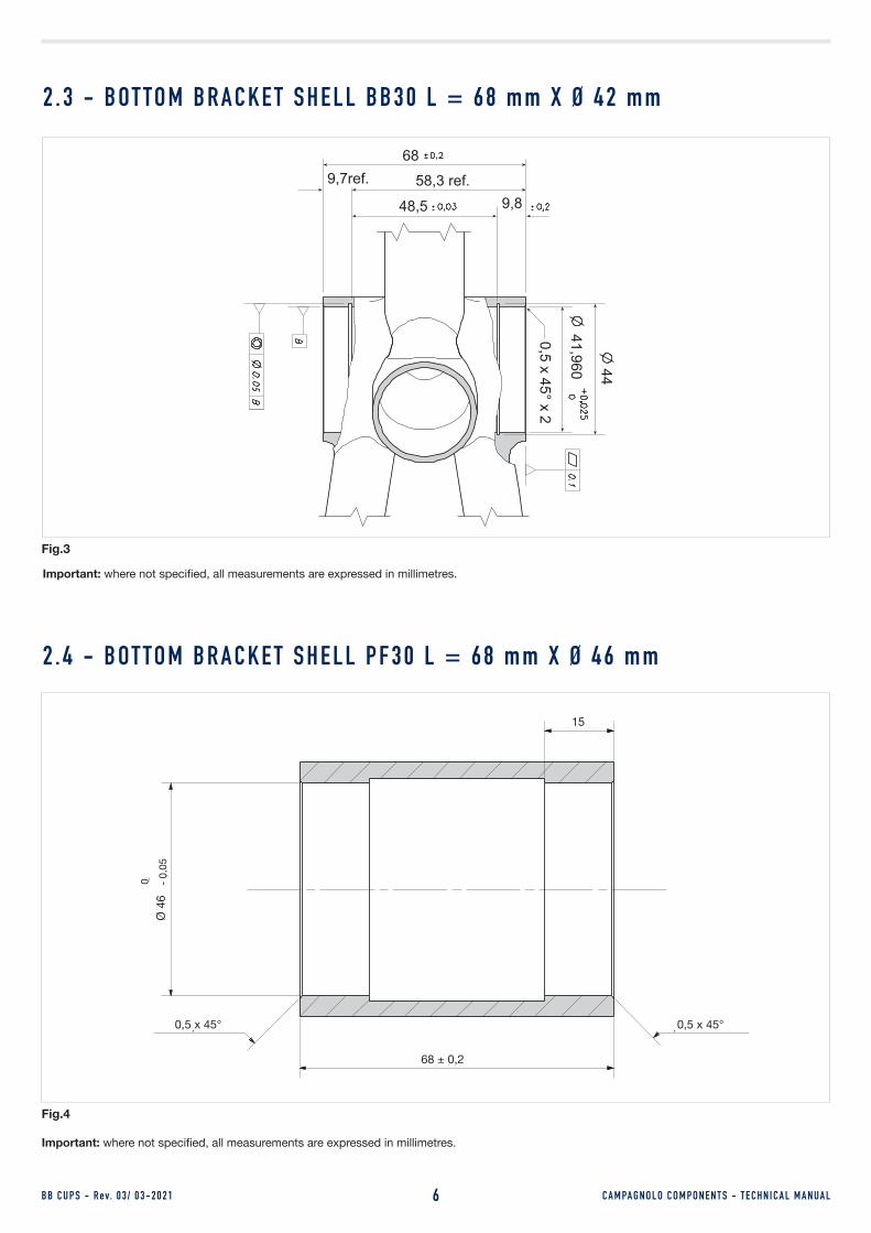
2 . 3 - B OT TO M B R A C K E T S H E L L B B 3 0 L = 6 8 m m X Ø 4 2 m m
44
41,960
0,5 x 45° x 2
9,8
9,7ref. 58,3 ref.
68
48,5
Important: where not specified, all measurements are expressed in millimetres.
15 mm
0,5 x 45°0,5 x 45°
68 ± 0,2 mm
0Ø
46
-0,0
5 m
m
68 ± 0,2
15
0,5 x 45°0,5 x 45°
Ø 4
60 -
0,05
Important: where not specified, all measurements are expressed in millimetres.
Fig.3
Fig.4
2 . 4 - B OT TO M B R A C K E T S H E L L P F 3 0 L = 6 8 m m X Ø 4 6 m m
C A M PA G N O L O C O M P O N E N T S - T E C H N I C A L M A N UA L7B B C U P S - R ev. 0 3 / 0 3 - 2 0 2 1
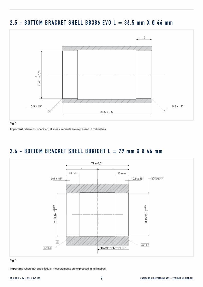
2 . 5 - B OT TO M B R A C K E T S H E L L B B 3 8 6 E V O L = 8 6 . 5 m m X Ø 4 6 m m
15 mm
86,5 ± 0,5 mm
0Ø
46
-0,0
5 m
m
0,5 x 45° 0,5 x 45°0,5 x 45° 0,5 x 45°
86,5 ± 0,5
15Ø
46
0 - 0,
05
Important: where not specified, all measurements are expressed in millimetres.
Fig.5
0,5 x 45°
79 ± 0,5
15 min
Ø 4
5,96
0 +
0,02
5
Important: where not specified, all measurements are expressed in millimetres.
2 . 6 - B OT TO M B R A C K E T S H E L L B B R I G H T L = 7 9 m m X Ø 4 6 m m
Fig.6
FRAME CENTERLINE
0,5 x 45°
15 min
Ø 4
5,96
0 +
0,02
5
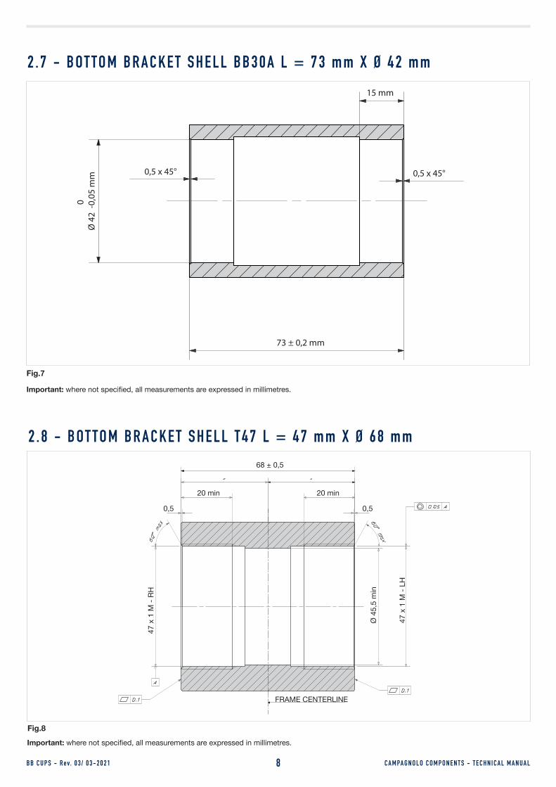
73 ± 0,2 mm
15 mm
0,5 x 45°0,5 x 45°
0Ø
42
-0,0
5 m
m
C A M PA G N O L O C O M P O N E N T S - T E C H N I C A L M A N UA L8B B C U P S - R ev. 0 3 / 0 3 - 2 0 2 1
2 . 7 - B OT TO M B R A C K E T S H E L L B B 3 0 A L = 7 3 m m X Ø 4 2 m m
Important: where not specified, all measurements are expressed in millimetres.
Fig.7
68 ± 0,5
20 min
Ø 4
5,5
min
47 x
1 M
- RH
Important: where not specified, all measurements are expressed in millimetres.
2 . 8 - B OT TO M B R A C K E T S H E L L T 4 7 L = 4 7 m m X Ø 6 8 m m
Fig.8
FRAME CENTERLINE
0,5
20 min
0,5
47 x
1 M
- LH

B B C U P S - R ev. 0 3 / 0 3 - 2 0 2 1 C A M PA G N O L O C O M P O N E N T S - T E C H N I C A L M A N UA L9
85,5 ± 0,5
20 min
Ø 4
5,5
min
47 x
1 M
- RH
Important: where not specified, all measurements are expressed in millimetres.
2 . 9 - B OT TO M B R A C K E T S H E L L T 4 7 L = 4 7 m m X Ø 8 6 m m
Fig.9
FRAME CENTERLINE
0,5
20 min
0,5
47 x
1 M
- LH
C A M PA G N O L O C O M P O N E N T S - T E C H N I C A L M A N UA L10B B C U P S - R ev. 0 3 / 0 3 - 2 0 2 1
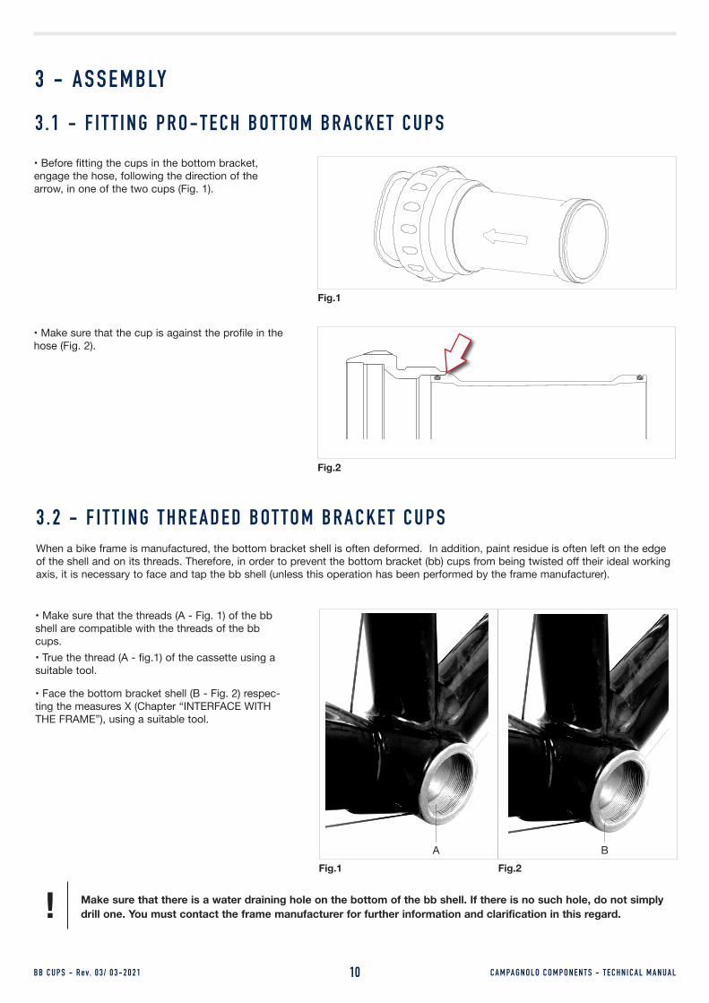
3 - A S S E M B LY
3 . 2 - F I T T I N G T H R E A D E D B OT TO M B R A C K E T C U P SWhen a bike frame is manufactured, the bottom bracket shell is often deformed. In addition, paint residue is often left on the edge of the shell and on its threads. Therefore, in order to prevent the bottom bracket (bb) cups from being twisted off their ideal working axis, it is necessary to face and tap the bb shell (unless this operation has been performed by the frame manufacturer).
• Make sure that the threads (A - Fig. 1) of the bb shell are compatible with the threads of the bb cups.• True the thread (A - fig.1) of the cassette using a suitable tool.
• Face the bottom bracket shell (B - Fig. 2) respec-ting the measures X (Chapter “INTERFACE WITH THE FRAME”), using a suitable tool.
A BFig.1 Fig.2
Make sure that there is a water draining hole on the bottom of the bb shell. If there is no such hole, do not simply drill one. You must contact the frame manufacturer for further information and clarification in this regard.!
3 . 1 - F I T T I N G P R O - T E C H B OT TO M B R A C K E T C U P S
• Before fitting the cups in the bottom bracket, engage the hose, following the direction of the arrow, in one of the two cups (Fig. 1).
Fig.1
• Make sure that the cup is against the profile in the hose (Fig. 2).
Fig.2

C A M PA G N O L O C O M P O N E N T S - T E C H N I C A L M A N UA L11
Campagnolo® UT-BB130
The right hand bottom bracket cup with English thread is a left hand thread.!
Fig.5 Fig.6
• Take the bb right cup, screw it in fully (Fig. 4) and tighten at 35 Nm (310 in.lbs) with the Campagnolo UT-BB130 tool and the torque wrench (Fig. 5).
• For T47 x 86 cups, use the BBT-47 Park Tool or a similar tool.
• Repeat the previous step with the left cup.
• Make sure that the bearing set are correctly grea-sed (Fig. 6).
B B C U P S - R ev. 0 3 / 0 3 - 2 0 2 1
• Identify the two holes in the groove of the right-hand cup (Fig. 7).
• Position the retaining spring so that the two ends are near the holes (Fig. 8).
Do not insert the spring fully.!
Fig.7 Fig.8
• Clean and degrease the threads of the bb shell (Fig. 3).
Fig.3 Fig.4
To know which bottom bracket cups are best suited for you, see the bottom bracket cup / crankset compatibility table on page 3.
!

C A M PA G N O L O C O M P O N E N T S - T E C H N I C A L M A N UA L12B B C U P S - R ev. 0 3 / 0 3 - 2 0 2 1
3 . 2 - M O U N T I N G O S - F I T B OT TO M B R A C K E T C U P S
3 . 2 . 1 - S TA N DA R D P R O C E D U R E• Press both bottom bracket cups into the bottom bracket until the bottom bracket cups encounter resistance and the O-ring enters the bottom bra-cket itself and is no longer visible (Fig. 1).
• Engage the tool UT-BB240 into the right hand bottom bracket cup to bring it into contact with the inner surface in the bottom bracket cup.
• Tighten the tool UT-BB240 into the left hand bot-tom bracket cup to bring it into contact with the bottom bracket cup itself (Fig. 2).
• Turn the lever of tool UT-BB240 clockwise until both bottom bracket cups are flush with the bottom bracket (Fig. 3).
Before removing the tool, check that the bottom bracket cups are installed correctly on the bottom bracket (Fig. 3).
Fig.3
Fig.2
Fig.1
• Turn the lever of tool UT-BB240 anticlockwise to unscrew the left hand bottom bracket cup comple-tely, then remove the screw (Fig. 4).
Fig.4

B B C U P S - R ev. 0 3 / 0 3 - 2 0 2 1 C A M PA G N O L O C O M P O N E N T S - T E C H N I C A L M A N UA L13
3 . 2 . 2 - P R O C E D U R E W I T H G L U E I N G
If the pairing complies with the specifications (indi-cated in Section 2), operation is ensured by the reciprocal dimensions. In the event that the bottom bracket shell does not comply with the foreseen tolerances, or in case of doubts, we recommend glueing the bottom bracket cups to the bottom bracket cup shell, following the procedure shown below.
• Thoroughly clean the inner surfaces of the bot-tom bracket shell which will mate with the bottom bracket cups (Fig. 1) with isopropyl alcohol and a cloth. Leave to dry completely.
• Thoroughly clean the outer surfaces of the bot-tom bracket cups (Fig. 1) with isopropyl alcohol and a cloth, and leave to dry. Do not touch the cleaned surfaces.
• To accelerate the curing time of the Loctite adhe-sive which will be used later in the procedure, apply Loctite Primer 7471 or Loctite Primer 7649 on all the surfaces of the bottom bracket shell which will be in contact with the bottom bracket cups (Fig. 2). Leave to dry for approximately 5 minutes then clean off any excess primer with isopropyl alcohol.
Repeat the previous procedure on the outer surface of the bottom bracket cups and leave to dry for approximately 5 minutes.
Fig.2
Fig.1
• Use a brush to carefully apply Loctite 603 (quicker drying) or Loctite 609 on the outer surfaces of the bottom bracket cups (Fig. 3).
• Clean the brush after use with isopropyl alcohol.
Fig.3
• Press both bottom bracket cups into the bottom bracket until the bottom bracket cups encounter resistance and the O-ring enters the bottom bra-cket itself and is no longer visible (Fig. 4).
Fig.4

B B C U P S - R ev. 0 3 / 0 3 - 2 0 2 1 C A M PA G N O L O C O M P O N E N T S - T E C H N I C A L M A N UA L14
• Engage the tool UT-BB240 into the right hand bottom bracket cup to bring it into contact with the inner surface in the bottom bracket cup.
• Tighten the tool UT-BB240 into the left hand bottom bracket cup to bring it into contact with the bottom bracket cup itself (Fig. 5).
• Turn the lever of tool UT-BB240 clockwise until both bottom bracket cups are flush with the bottom bracket (Fig. 6).
• Before removing the tool, check that the bottom bracket cups are installed correctly on the bottom bracket (Fig. 6).
Fig.6
Fig.5
• Turn the lever of tool UT-BB240 anticlockwise to unscrew the left hand bottom bracket cup comple-tely, then remove the screw (Fig. 7).
• Clean off any excess Loctite with isopropyl alcohol and wait approximately 24 hours before using the bicycle to be sure that the adhesive has cured completely.
Fig.7
C A M PA G N O L O C O M P O N E N T S - T E C H N I C A L M A N UA L15
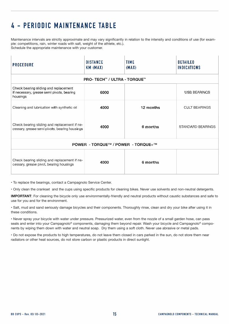
4 - P E R I O D I C M A I N T E N A N C E TA B L EMaintenance intervals are strictly approximate and may vary significantly in relation to the intensity and conditions of use (for exam-ple: competitions, rain, winter roads with salt, weight of the athlete, etc.). Schedule the appropriate maintenance with your customer.
B B C U P S - R ev. 0 3 / 0 3 - 2 0 2 1
P R O C E D U R E D I S TA N C E K M ( M A X )
T I M E ( M A X )
D E TA I L E DI N D I C AT I O N S
Check bearing sliding and replacement if necessary, grease semi pivots, bearing housings
USB BEARINGS
Check bearing sliding and replacement if ne-cessary, grease semi pivots, bearing housings
Check bearing sliding and replacement if ne-cessary, grease pivot, bearing housings
• To replace the bearings, contact a Campagnolo Service Center.
• Only clean the crankset and the cups using specific products for cleaning bikes. Never use solvents and non-neutral detergents.
IMPORTANT: For cleaning the bicycle only use environmentally-friendly and neutral products without caustic substances and safe to use for you and for the environment.
• Salt, mud and sand seriously damage bicycles and their components. Thoroughly rinse, clean and dry your bike after using it in these conditions.
• Never spray your bicycle with water under pressure. Pressurized water, even from the nozzle of a small garden hose, can pass seals and enter into your Campagnolo® components, damaging them beyond repair. Wash your bicycle and Campagnolo® compo-nents by wiping them down with water and neutral soap. Dry them using a soft cloth. Never use abrasive or metal pads.
• Do not expose the products to high temperatures, do not leave them closed in cars parked in the sun, do not store them near radiators or other heat sources, do not store carbon or plastic products in direct sunlight.


