This document provides a complete reference to all menus, functions, andfeatures of the BCD396XT Digital Trunk Tracker Scanner from Uniden. It isbased on the Operation Specification that is used both as a guide to the
implemented.
Some proprietary information has been removed, formatting has beenmodified, and extensive editing has been performed to make the text more readable. However, you will almost certainly find a handful of oddturns of phrases. Mostly, though, we hope that this reference work can help you better
intended to be a
available to scanner users online, you now have more information than ever on every facet of your scanner.
CTCSS/DCS CODE LIST .............................................................................................264
Friday, November 07, 2008 8
Feature Summary
Band Coverage Frequency (MHz)
Modulation Step (kHz) RemarkLower Edge Upper Edge25.0000 26.9600 AM 5.0 Petroleum Products & Broadcast Pickup26.9650 27.4050 AM 5.0 CB Class D Channel27.4100 27.9950 AM 5.0 Business & Forest Products28.0000 29.6800 NFM 20.0 10 Meter Amateur Band29.7000 49.9900 NFM 10.0 VHF Low Band50.0000 53.9800 NFM 20.0 6 Meter Amateur Band54.0000 71.9500 WFM 50.0 VHF TV Broadcast 2 472.0000 75.9950 FM 5.0 Intersystem & Astronomy76.0000 87.9500 WFM 50.0 VHF TV Broadcast 5 688.0000 107.9000 FMB 100.0 FM Broadcast 108.0000 136.9916 AM 8.33 Aircraft Band137.0000 143.9875 NFM 12.5 Military Land Mobile144.0000 147.9950 NFM 5.0 2 Meter Amateur Band148.0000 150.7875 NFM 12.5 Military Land Mobile150.8000 161.9950 NFM 5.0 VHF High Band162.0000 173.9875 NFM 12.5 Federal Government174.0000 215.9500 WFM 50.0 TV Broadcast 7 13216.0000 224.9800 NFM 20.0 1.25 Meter Amateur Band225.0000 379.9750 AM 25.0 UHF Aircraft Band380.0000 399.9875 NFM 12.5 Military Band400.0000 405.9875 NFM 12.5 Miscellaneous406.0000 419.9875 NFM 12.5 Federal Government Land Mobile420.0000 449.9875 NFM 12.5 70 cm Amateur Band450.0000 469.9875 NFM 12.5 UHF Standard Band470.0000 512.0000 NFM 12.5 UHF TV763.0000 775.9937 NFM 6.25 Public Service Band793.0000 805.9937 NFM 6.25 Public Service Band806.0000 823.9875 NFM 12.5 Public Service Band849.0125 868.9875 NFM 12.5 Public Service Band894.0125 960.0000 NFM 12.5 Public Service Band1240.0000 1300.0000 NFM 25.0 25 cm Amateur Band
Notes on Band Coverage:
You can edit the Modulation and Step for each band. The above table shows the factorydefault values.
Although TV bands are listed, the BCD396XT cannot decode Digital TV audio.
Friday, November 07, 2008 9
ChannelsDynamic You can create up to 25,000 total conventional channels, trunked channels, and trunked systemfrequencies.
Channels in a conventional system contain a frequency.Channels in a trunked system contain a talk group ID (TGID).
Memory ArchitectureAbsolute Limits:
Systems 500
Sites Total 1,000
Sites/System 256
Channel Groups per System 20
Channels+System Frequencies 25,000
Channels per conventional system
1000
Channels per trunked system 500
Trunk Frequencies per Site 500-1000 (depending on total TGIDs stored in the system)
Notes about limits: The actual results will be limited by the first absolute limit you hit. For example, if youhave created 1000 sites, you will not be able to create a new system even though you havecreated fewer than 500 systems.
You can check the % of memory used by using the menu.
Channel Memory ScanThe scanner can scan any combination of trunked and conventional systems simultaneously.
Priority ScanThe scanner checks conventional priority channels every 1-10 seconds (2 seconds default) when scanning a conventional system.
Priority Plus ScanThe scanner scans only the conventional priority channels.
Search with ScanThe scanner can do Service and Custom Searches along with system scanning.
Scan Speed100 Channels/Second (max) for conventional systems.
Friday, November 07, 2008 10
Scanning LockoutYou can lock out any System, Site, Channel Group, Channel, or search frequency.
Locked out channels are skipped (or ignored) during scanning.
If a system, site, or channel group is locked, all channels belonging to it will be skipped during scanning.
Temporary Lockout Sites, Systems, Channels, or Frequencies temporarily locked out are automatically unlocked when power is cycled.
Quick KeysYou can assign an SQK (System/Site/Search Quick Key) from 0-99.
You can assign a GQK (channel Group Quick Key) from 0-9.
Quick keys can be rapidly enabled/disabled from the keypad during scanning.
Startup ConfigurationYou can assign a startup configuration key to a system or search range so that it can be automaticallylocked out or unlocked during power up.
Channel AlertYou can set a separate audible/visual alert for each channel.
Alpha TaggingYou can assign an alphanumeric name to each System, Site, Channel Group, Channel, Location, Customsearch range, SAME group, and Tone-Out. You can use 16 characters per tag.
Duplicate Input AlertThe scanner will alert you if an entered alpha tag, frequency, etc has already been used in the samesystem.
Number TagYou can assign a unique number tag from 0-999 to each system and to each channel within a system. This tag allows you to rapidly tune to a specific channel.
Trunk TrackingThe scanner can track the following types of trunked systems:
Motorola Type I 800
Motorola Type II 800, 900, UHF, VHF
Motorola Rebanded
EDACS Wide, Narrow, SCAT
EDACS ESK (No ProVoice Decoding)
LTR
APCO P25 Standard, P25 One-Frequency
Friday, November 07, 2008 11
Multi-Site SystemAll trunked systems can have more than one site. All sites in the system share the same Channel Groups and Channels.
Control Channel Only Trunk Tracking can be achieved by entering only the control channels for Motorola and P25 systems.
P25 One-Frequency TrunkingThe scanner can follow individual talk groups on P25 single-frequency systems that use both NAC and
s for squelch control and user identification. ID Search and ID Store are available, just like on trunkedsystems.
Priority ID ScanningTrunked channels can be assigned priority. When the scanner is monitoring the control channel, channels you tag as priority are given a higher priority over non-priority channels when they become active.
Preemptive Priority ID ScanningFor Motorola systems that have channel priority active on the system, if you flag a channel as priority andthe system also has that TGID identified as a priority channel, the scanner will preempt any currenttransmission if the TGID becomes active.
Trunking Activity IndicatorsThe scanner shows all trunked activity when you hold on the control channel.
Custom SearchYou can program up to 10 custom search ranges and either search them exclusively or include these searches when scanning.
Quick SearchIf you hold on a conventional channel, you can start searching from the current frequency. If you hold on a trunked channel, you can quickly switch to ID Search mode.
Frequency AutostoreThe scanner can automatically store frequencies found during a search.
Search Speed / Turbo Search100 Steps/Second in search mode (max, except for 5 kHz steps)300 Steps/Second in search mode (max, 5 kHz steps) Turbo mode automatically applies to 5 kHz step searches.
Friday, November 07, 2008 12
Search LockoutYou can lock out up to 500 frequencies.
The limit of temporary L/O frequencies: 250
The limit of permanent L/O frequencies: 250
Locked out frequencies will be skipped in Search Mode or Close Call Mode.
You can review all locked out frequencies in Menu Mode.
Search KeySearch keys are short cuts to start searching for a single search range.
There are 3 search keys (sr1 to sr3).
Service SearchYou can search preset frequencies typically used by specific agencies or groups.
The kind of Service Search is as follows: Public Safety, News, HAM Radio, Marine, Railroad, Air, CB Radio,FRS/GMRS/MURS, Racing, FM Broadcast, Military Air, Special
Broadcast ScreenAllows the scanner to ignore hits on Pager, FM, UHF TV, VHF TV, NOAA WX and custom band frequencies.
AttenuatorYou can attenuate the incoming signal for channels that get interference from strong signal sources.
You can set a global attenuator to apply attenuation to all reception.
Code SearchRapid search for the CTCSS/DCS used during a transmission.
The scanner does not detect or decode P25 signals if you are operating CTCSS/DCS Search.
P25 NACP25 Network Access Code (NAC) is used to provide selective squelch operation on channels. The scannercan also search for the NAC code that is being used on a P25 digital channel.
Volume OffsetAdjust the volume level for any channel from -3 to +3 steps to balance audio level.
IF Exchange Switches the current frequency to use a different IF (intermediate frequency) for receiving radio signals toavoid interference.
Friday, November 07, 2008 13
Dropout DelayControls whether the scanner pauses at the end of a transmission to wait for a reply.
You can set the Delay time for each System. All Channels in the System share the same delay setting. Youcan also set the Delay time for Search, Close Call and Tone-Out.
You can set the minus delay time. In that case, the scanner only stops on transmissions for the set duration, then automatically resumes.
Weather and SAME AlertThe scanner can alert to Weather Alert Tone, all FIPS or selected FIPS.
Close Call® Frequency CaptureThe scanner can immediately detect and lock onto a transmission above threshold signal strength.
Close Call Temporary StoreThe scanner scans the last 10 frequencies captured by Close Call so that you can continue to receive thesignal even after the signal is not strong enough to trigger a Close Call hit..
Tone-Out Sequential Decode Lets you set the scanner to act as a two-tone pager for fire tone-out standby. If you do not know the tones being used, the scanner can detect the tones when it receives a page.
Location-Based Scanning* The scanner can automatically lock and unlock systems, sites and channel groups based on your currentlocation as provided by an external GPS unit (not included).
Location Alert System* The scanner alerts you when you approached a stored location.
Navigation Modes* Indicate the Direction / Distance / Time to Goal for locations you set.
GPS Compatibility*Compatible GPS units output location data that conforms to NMEA-0183 v3.01. The scanner uses the GGA and RMC sentences as defined by that specification. Note that this standard specifies an RS232 serial connection. GPS units that have USB connectivity are not compatible with this scanner.
Wired CloningYou can clone all programmed data, including Memory Architecture, Menu settings and other parameters from one BCD396XT to another BCD396XT connected with RS232C cable.
Band Scope Band Scope Mode searches a frequency range and displays a graphic of the signal level in real time.
In Band Scope Hold Mode, the user can monitor the frequency displayed.
Friday, November 07, 2008 14
PC ControlYou can download information into the scanner and control the scanner via your personal computer.
LCD and Keypad BacklightYou can select your desired LCD backlight color from White, Red, Magenta, Blue, Green, Cyan, or Yellow.
The Keypad backlight is single white.
The backlight can be adjusted to 3 different brightness levels
Alert Tone LevelThis feature lets you adjust the volume level of the following tones: Key Beep, Emergency Alert, ChannelAlert, Close Call Alert, Tone-Out detection Alert, Battery Low Alert and Location Alert.
Battery Low AlertWhen the battery voltage becomes low, the icon will blink and a Battery Low Tone will be generatedevery 15 seconds. This alert level is set at the same level as the key beep volume level.
Battery SaveYou can turn on/off this function by Menu Operation.
This works when there is no transmission over 1 minute in the following modes. This feature turns off RF power for 1 second and turns on it 300 ms to extend the battery life.
Scan Hold Mode at a Channel of conventional System (without Priority Scan)
Any Search Hold Mode
Key LockThis feature disables the keypad and scroll to prevent any accidental input.
Key Safe Mode This mode helps keep novice users from accidentally changing parameters or modes.
Some keys don't work in this mode.
Audio AGCThe scanner judges strength of the signal and changes the volume automatically.
Repeater Reverse One-touch key lets you switch to hearing the input frequency on a conventional repeater system ortrunked system.
Memory BackupScanner memory is backed up semi permanently.
Friday, November 07, 2008 15
Design The below is a design reference. There might be some differences between this image and the actual final design.
Friday, November 07, 2008 16
Controls and KeysLong press means pressing a key more than 2 second.
.
Normal Mode:Normal Mode means that the scanner is not in Function Mode. In this mode, the F icon is not displayed.
Function Mode:Pressing [FUNC] puts the scanner into Function Mode for 3 seconds. While it is in Function Mode,the scanner displays the F icon. If you press a button, the Function Mode time is continued foranother 3 seconds.
Long pressing [FUNC] puts the scanner into Function Mode without a timeout. The scannerdisplays Function Key and Holding , and the F icon blinks.
Pressing [FUNC] again in each Function Mode returns to Normal Mode and the F icon disappears.
Scroll ControlSelects a channel or frequency in Hold Mode.
Selects Menu items in Menu Mode.
Selects a character while editing the Name.
Sets the level in Volume / Squelch Level Control mode.
Scroll Control PushPressing this works the same operation as pressing [E / yes / gps] in Menu Mode.
Press this to set the volume level in the mode that is not Menu Mode.
Function + Scroll ControlUse to select a System in Scan or Scan Hold Mode.
Function + Scroll Control PushPress this to set the squelch level in any mode other than Menu Mode.
Scan / srch (Search) KeyPress to resume scanning. (Scan Hold Mode and while monitoring a channel in Scan Mode)
Press to go to Scan Mode. (Except Scan Mode, Scan Hold Mode and GPS Mode)
Function + Scan / srch KeyPress to resume searching. (Search Hold Mode and while monitoring in Search Mode)
Press to toggle between ID SCAN and ID SEARCH while scanning a trunked system.
Press to display the Quick Search Prompt. (Except in Search Mode, Search Hold Mode, GPS Modeand Band Scope Mode)
Press to return to the scanner screen. (GPS Mode)
Press to change the band scope search type. ( Band Scope Mode)
Hold / (Close Call) KeyPress to go to each Hold Mode. (Scan Mode, Search Mode, Close Call Only Mode, WX Scan Modeand Band Scope Mode)
In Close Call Only Mode, the scanner sounds an Error Tone if it has not yet gotten a hit.
Press to resume scanning or searching. (Hold Mode)
Function + Hold / KeyToggles the setting of Close Call.
Long press to start Close Call Only Mode.
L/O (Lockout) KeyPress once to temporarily lock out a system channel, a search frequency or a location data. This lock out is canceled when the power is turned off then back on.
Press twice within one second to permanently lock out a system channel, a search frequency or a location data. This lockout remains even if the power is turned off.
Long press to unlock all settings of the current system. (Scan Mode and Scan Hold Mode)
All Locations of the current Type are unlocked by long-pressing this key. (Review Location Mode)
The scanner unlocks all frequencies of Global Lockout List*. (Search Mode, Search Hold Mode,Close Call Only Mode and Close Call Hold Mode)
Press to cancel a prompt without changing settings in Menu Mode.
*Global Lockout List means collecting the locked out frequencies at Search Mode, Search Hold Mode,Close Call Only Mode and Close Call Hold Mode.
Friday, November 07, 2008 18
Function + L/O KeyPress once to temporarily lock out the current system, current site or current search range in Scan Mode and Scan Hold Mode. This lock out is cleared when power is turned off then back on.
Press twice in a second to permanently lock out the current system or current search range in Scan Mode and Scan Hold Mode. This locked out is kept even if the power is turned off.
Press to go to Rvw Search L/O. (Search Mode, Search Hold Mode, Close Call Only Mode and Close Call Hold Mode)
Long press to display the prompt to unlock all systems, sites, search ranges and Close Call Hits system and enable all Quick Keys for systems/sites/search ranges. (Scan Mode and Scan HoldMode) If you press [E / yes / gps], the scanner unlocks all data. If you press [. / no / pri], thescanner returns to the previous mode without unlocking.
Long press to display the prompt for unlocking all Locations of all types. (Review Location Mode ofGPS Mode) If you press [E / yes / gps], the scanner unlocks all data. If you press [. / no / pri], thescanner returns to the previous mode without unlocking.
(Light) / (Power) / (Key Lock)Press to illuminate the LCD back light according to Menu setting.
Press and hold to turn the scanner on or off.
Function + / / KeyPress to lock or unlock the keypad.
1 - 9, 0 KeyPress to enable or disable the System/Site/Search Quick Key for system or search range. (Scan Mode)
Press to turn on or off each custom search range number. These keys operate only in CustomSearch and not in other searches. (Search Mode)
Press to go to Direct Entry Mode or to enter a Number Tag. (All Hold Mode, Close Call Mode andTone-Out Mode)
While editing a name, press [4 / LEFT] or [6 / RIGHT] to move the cursor to the left or right.
Function + 1 - 9, 0 KeyPress to enable or disable Groups Quick Key in Scan Mode.
Function + 1 - 3 / sr1 - 3 (Search) KeyPress [1 3 / sr1 - 3] to start Service Search, Custom Search, Tone-Out Mode or Band Scope Modein Set Search Key. (except Scan Mode and GPS Mode)
Function + 4 / LEFT / ifx (IF Exchange) KeyPress to exchange the IF (intermediate frequency) for receiving radio signals to avoid interference.(except Scan Mode and GPS Mode)
Function + 5 / lvl (Volume Offset) KeyPress to change the volume offset level. (Scan Hold Mode)
Friday, November 07, 2008 19
Function + 6 / RIGHT / disp KeyPress to change the Display Mode. (Scan Hold Mode and Custom Search Mode)(Display mode 1 -> Display mode 2 -> Display mode 3 -> Display mode 1 -Press to change the GPS Display. (GPS Mode)
Function + 7 / att (Attenuator) KeyPress to toggle the attenuation state. (except GPS Mode)
Long press to toggle global attenuator. (except GPS Mode)
Function + 8 / rev (Reverse) KeyPress to monitor the reverse frequency. It returns to current frequency whenthe key is released. (Scan Hold Mode, Search Mode, Search Hold Mode, Close Call Only Mode andClose Call Hold Mode)
Function + 9 / mod (Modulation) KeyPress to change the modulation state. (except GPS Mode and WX Scan Mode)
Function + 0 / wx (Weather) KeyPress to toggle WX Scan Mode and WX Alert Scan Mode while WX Scan or WX Alert Scan.
Press to toggle WX Alert Priority. (except WX Scan Mode)
Long press to start WX Scan. (except WX Scan Mode)
. (Decimal) / no / pri (Priority) KeyPress to cancel these displays while displaying Error or Warning message.
Press to input "."(decimal) for frequency.
Press to input "-" or "i" for TGID.
Press to input a space in editing a data name.
Press twice to clear the data in editing data name.
- -Out Mode.
Press in Scan Mode to start the selection for the ten's place of a System/Site/Search Quick Key.Then, press number key to jump to each number's place of a Quick Key.
Function + . / no / pri KeyPress to toggle Priority Mode in Scan Mode. (On / Plus On / Off)
E (Enter) / yes / gps KeyPress to accept the input data or a Menu Item.
Press to edit the channel data. (Scan Mode and Scan Hold Mode)
Press to quickly save the frequency in Search Mode, Search Hold Mode, Close Call Mode, Close CallHold Mode, WX Scan Mode and WX Scan Hold Mode.
Press to go to the editing menu for current Tone-Out.
Press to go to Review Location Mode. (GPS Mode)
Function + E / yes / gps KeyPress to change GPS Mode.
Long press to store a current location data.
Friday, November 07, 2008 20
Menu KeyPress to enter the Menu Mode.
Press to go back up one menu level when in the Menu Mode.
Press after entering the value to indicate going to a number tagged system or channel.
Function + Menu KeyPress to go to the editing menu for the current system, search range or location data.
Friday, November 07, 2008 21
Displays
LCD Design The reference design shown below is for illustration purposes only and is not intended to be aphotorealistic representation of the display.
IconsSx: : This icon appears with icons of System and Site Quick Key numbers (from 0 to
99 ). x shows the current ten s place of Quick Keys for Systems or Sites.
GRP: This icon appears with icons of Quick Key number for Channel Groups (1 - 9, 0).
1 - 9, 0: In SCAN mode, the numbers of unlocked Quick Key for Systems/Channel Groupare displayed. The number for the currently scanned SQK set flashes.
In SCAN HOLD mode, the Quick Key number for the current System/ChannelGroup appears.
Enabled User Range numbers appear in Custom Search; thenumber blinks.
HOLD: This icon appears in Scan Hold, Search Hold and Close Call Hold Mode.
L/O: This icon appears at a locked out Channel or frequency.
PRI : This icon turns on during Priority Scan and this blinks during Priority Plus.
GPS: This icon appears when the scanner receives GPS data. This shows in the sameplace as " ".
AM / FM / NFM / FMB
/ WFM: These icons show the modulation type.
ATT: This icon appears when a channel has attenuator on and blinks when global attenuator is on.
P25: This icon shows the receiving digitalized voice of APCO P25.
Friday, November 07, 2008 22
LNK: This icon appears when data is received on a VOICE CHANNEL. This shows in thesame place as "P25".
DAT: This icon appears when data on CONTROL CHANNEL is received. This shows inthe same place as "P25" icon.
ENC: This icon appears when encrypted APCO P25 digitized voice is received. Thescanner mutes audio. This shows in the same place as "P25".
C67. 0 / DCS023 / NAC: 000 / etc.: The scanner displays the CTCSS/DCS/P25 NAC here. This shows in the same
place as "P25".
SCR: This icon appears when one or more Broadcast Screen Band is set to on.
WX: This icon turns on while the Weather Alert Priority Scan works.
F (Function icon) : This icon appears in Function Mode. Function Mode does not have a timeoutwhen this icon blinks.
P (Priority Channel) : This icon appears when the channel set to
(Signal Indicator) : This icon shows strength of the signal from 0 to 5.
(KEYPAD LOCK): This icon will appear only when the KEYLOCK function is On.
(BATTERY Low Alert): This icon blinks when the battery voltage is low. This icon blinks when a bad battery is installed and an AC adapter is connected. This icon appears duringbattery check.
(Close Call Pri ) : This icon appears in Close Call Priority Mode. This blinks in Close Call Only Mode
or when the scanner gets a Close Call hit.
(Close Call DND) : This icon appears in Close Call DND Mode is CC DND Mode. This is a reverse
display of Close Call Pri icon.
Dot MatrixThe display element consists of a 128 x 64 pixel display. See Font Data for character patterns.
Since the display is entirely dot matrix, a great variety of different things can be shown. The above shows the most common display elements in most modes. Additional examples are shown throughout this reference guide.
LCD Flashing TimeAbout 500 mS on/500 mS off (1 Hz).
Friday, November 07, 2008 23
TonesThe scanner can produce 3 fundamental tones, high (1200 Hz), middle (920 Hz), and low (640 Hz).Furthermore, there are Alert Tones and Weather Alert Sirens which include other sounds.
Additionally, special alert tones (Location Alert, CC alert, Emergency alert and WX alert, etc) can be set to custom volume levels.
General TonesKey Touch ToneWhen you press valid keys, the scanner will sound single high beep for 50 mS.
Confirmation ToneThe scanner will sound double high beep for confirmation (50 ms beep - 100 ms silent - 50 ms beep).
Exec ToneWhen you press [E / yes / gps] key etc. to accept the entry or setting, the scanner will sound high-middlebeep (75 ms high beep - 25 ms silent - 75 ms middle beep).
Error ToneWhen you press a key that does not have a valid function in the current mode, the scanner will sound a triple low beep (75 ms beep - 25 ms silent -- repeat 2 times)
Weather Alert SirensThe scanner sounds the following tones until any key is pressed, or for 8 seconds.
For Warning[100 ms 120 Hz - (20 ms every 150 - 195 Hz in 5 Hz step) - (30 ms every 200 - 590 Hz in 10 Hz step) - 500 ms600 Hz - 100 ms silent] --- repeat
For Watch[(50 ms 800 Hz - 30 ms silent - 50 ms 1050 Hz - 30 ms silent) -- repeat 3 times - 170 ms silent] --- repeat
For Advisory[100 ms 800 Hz - 50 ms silent - 100 ms 1050 Hz - 500 ms silent] - repeat
For Weather Alert Tone: Same as Weather Alert Siren For Warning.
Friday, November 07, 2008 24
Tones in Menu Mode
Selecting a menu itemAs you step to the next menu item by turning [Scroll Control] knob, the scanner will sound a single highbeep for 100 ms.
However, if the menu item is the last item and you turn [Scroll Control] knob in the clockwise direction, thescanner will sound a double high beep (75 ms beep - 25 ms silent - 75 ms beep).
When you select a menu item by pressing [E / yes / gps] key, the scanner will sound a single middle beepfor 100 ms.
Or, when you return to a previous menu by pressing [MENU] key, the scanner will sound a double middlebeep (75 ms beep - 25 ms silent - 75 ms beep).
Editing a name or a frequency etcWhen you select letters, the scanner sounds a single high beep for every click of the [Scroll Control] knob.
When you move the cursor from the left to the right, the scanner will sound a single middle beep (100 ms). Or, when you move the cursor from the right to the left, the scanner will sound a double middle beep (75ms beep - 25 ms silent - 75 ms beep).
If you store data by pressing [E / yes / gps], the scanner sounds the Exec Tone.
Alert in Scanner Mode You can select channel or frequency alert from Alert1-9 in Menu by "Set Alert" and "Emergency Alert".
Each alert has a unique pattern of tones.
Alert in GPS Mode
Alert for Point Of Interest You can select a location alert from Alert 1 to Alert 4 in Menu. Each alert provides a unique pattern oftones.
Alert for Dangerous XingThe alert for Dangerous Xing is a fixed three-tone sequence.
Alert for Dangerous RoadThe alert for Dangerous Road is a fixed five-tone sequence.
Battery Low ToneAt the low battery voltage level, the scanner will sound a single low beep (100 ms) every 15 seconds.
Friday, November 07, 2008 25
OperationNOTE: Valid keys for the "Press Any Key" prompt are all keys except for [ / / ]. Pressing [ / / ] always turns on or off the backlight. And specially, pressing [L/O] cancels the prompt and exit from any Menu and so on immediately.
Power OnPress [ / / ] for 1 second to turn on the scanner.
The scanner displays the opening screen and the copyright notice, and finally goes to the LAST MODE. Thelast select GPS Display mode is also backed up.
Notes on the Last Mode:LAST MODE means the mode when the scanner is turned off. It resumes Scan Mode,Custom/Service/Quick Search Mode, Weather Mode, Close Call Only, Tone-Out Mode, each HoldMode, GPS Mode and Band Scope Mode for LAST MODE.
In ID Search Hold Mode if ID has already been registered, LAST MODE will be ID Search Hold Mode.If ID has not been registered yet, LAST MODE will be Scan Mode.
Review Location Mode is set to normal Scanner Mode (not GPS Mode).
Uni den BearcatBCD396XTDi gi tal Trunki ngDynami c Scanni ng
Copyri ght 2009Uni den Ameri caCorp. All Ri ghtsReserved.
Opening Screen Copyright Notice Screen
Friday, November 07, 2008 26
Volume and Squelch ControlVolume and Squelch can be adjusted by rotating the [Scroll Control] in the following modes: Scan Mode,Scan Hold Mode, Search Mode, Search Hold Mode, Tone-Out Mode, Weather Scan Mode, Close Call OnlyMode, Band Scope Mode, Band Scope Hold Mode.
Volume Adjust ModeTo adjust the volume level, press [Scroll Control]. When the volume level indicator appears, rotate [ScrollControl] to change the volume level.
You can set the volume level from 0 to 15.
Volume Adjustment
Press [Scroll Control] again or wait for 10 seconds to quit from the volume level control mode.
Press [Function] + [Scroll Control] to enter the P25 Condition Mode.
Squelch Adjust Mode To adjust the squelch level, press [Function] + [Scroll Control]. When the squelch level indicator appears, rotate [Scroll Control] to change the squelch level.
The squelch level can set from 0 to 15.
Squelch Adjustment
Press [Scroll Control] key again or wait for 10 seconds to quit from the squelch level control mode.
Press [Function] + [Scroll Control] key to enter the P25 Condition Mode.
PRI 3. 87
System 125. 0000MHzAM
SQUELCH LEVEL 11
Battery Voltage
PRI 3. 87
System 125. 0000MHzAM
VOLUME LEVEL 11
Battery Voltage
Friday, November 07, 2008 27
P25 Condition ModePress [Function] + [Scroll Control] key to go to P25 Condition mode in Volume / Squelch Adjust mode.
You can see the current status of APCO decoding and the threshold values in this mode.
P25 Condition
T 1. 25 1. 58 1. 80 indicates the threshold voltage. The specific values will be determined by your setup.
The number following ERR: indicates the APCO decoder error rate.
This number preceding AUTO shows threshold value.
Press [Scroll Control] key or [Function] + [Scroll Control] key to quit the P25 Condition Mode. This modedoesn't have a time-out.
State Transition Diagram
Normal Mode Volume Adjust
Squelch AdjustP25 ConditionPush [F]+[Scroll Ctrl]
Push [Scroll Ctrl]
Push [F]+[Scroll Ctrl]
Push [F]+[Scroll Ctrl]
Push [Scroll Ctrl]Push [F]+[Scroll Ctrl]
Push [Scroll Ctrl]
PRI 3. 87
System 125. 0000MHzNFM P25
ERR: 14 8 AUTOT 1. 25 1. 58 1. 80
Battery Voltage
Friday, November 07, 2008 28
Menu Mode
General Operations
Key Operation To enter the Menu Mode: Press [Menu]
To select a Menu item: Turn [Scroll Control]
To select a Menu item or input data: Press [E / yes / gps] or tap the [Scroll Control]
To Return to the previous: Press [Menu]
To exit from Menu Mode:Press [Scan / srch] to go to Scan ModePress [Hold / ] to go to Scan Hold ModePress [Menu] at Top Menu to return to previous modePress [L/O] to exit Menu and return to previous mode
Notes: Tapping the [Scroll Control] can be used instead of [E / yes / gps] in Menu Mode or at variousprompts. NEXT item is a lower item in this document. Therefore, the next item of the lowest Item is highest item.Menu items are described as the bold letter in this specification.
Display Format in Menu Mode The Menu Item screen is four-line mode.
The first line displays the Menu Item Name and the selection items are displayed below.
For example, the Menu display of a channel modulation setting is as follows.
Select an item by turning [Scroll Control] until the item is highlighted, then pressing [E / yes / gps].
Set Modulati onAutoAMNFM
Friday, November 07, 2008 29
Edit NameThe editing cursor is displayed. Turn [Scroll Control] to choose the character and the cursor stays at thehighlighted position. The display is the following.
Press [4 / LEFT / ifx] to move the cursor to the left and [6 / RIGHT / disp] to move it to the right.
Press [. / no / pri] once to erase one character with the cursor. Press it twice to erase all characters.
If the inputted name exists already in the same category, the scanner beeps Confirmation Tone anddisplays "Name Exists" and "Accept? (Y/N)".
A system name is the same as a service search range name, custom search range name or othersystem name.A group name is the same as another group name in the same system.A channel name is the same as another channel name in the same group.A custom search range name is the same as a system name, service search range name or othercustom search range name.A SAME name is the same as another SAME name.A Tone-Out name is the same as another Tone-Out name.
Name Exi stsAccept? ( Y/N)
Press [E / yes / gps] to ignore the message and set the name. Then it proceeds to next step.
Press [. / no / pri] to return to the name editing state.
Note: If the user name has no character, the scanner prompts "Set Default Name" and "OK? (Y/N)".
Set Default NameOK? ( Y/N)
Press [E / yes / gps] to set Name to the default name. Press [. / no / pri] to return to name editing.
Edi t NameSystem 1 C
4 cursor 6
Friday, November 07, 2008 30
Edit Frequency and Set ToneThe editing cursor is displayed.
Press a number key to enter each digit and press the decimal key to input a decimal point.
The cursor moves to the left or the right by turning [Scroll Control] knob.
If you press the decimal key when a decimal point is already entered, the frequency data is cleared andthe editing cursor moves to the first position.
The stored frequency is determined by the following:The entered frequency is stored if it can be divided by a valid step.If it cannot be divided by a valid step, the scanner stores the nearer frequency at a frequency of5kHz step or a frequency of 6.25kHz step. So, you must input the correct frequency to store a frequency of 7.5 kHz step or 8.33 kHz step. (See: Band Coverage)
If the frequency is out of the range in Band Coverage, the scanner displays "Out of Band", Press Any Keyand sounds an Error Tone. Press any key to return to editing mode.
Out of Band
Press Any Key
For Channel Frequencies in conventional System, if the entered frequency is already stored into the sameGroup, it displays "Frequency Exists" Accept? (Y/N) and sounds a Confirmation Tone. Press [E / yes / gps] to ignore message and proceed to next step. Or press [. / no / pri] to return to the editing mode.
FrequencyExi sts
Accept? ( Y/N)
Edit Talk Group IDDecimal TGID editThe editing cursor is displayed.
Press a number key to enter the TGID and press the decimal key to enter a hyphen. The cursor moves tothe right by entering a number or hyphen.
Press the decimal key first to set "i" for I-Call entries. Then press the number keys to enter the I-Call ID.
Turn the [Scroll Control] to move the cursor position from left end to next to right end character, or fromleft end to right end character when you have already entered the maximum length.
Friday, November 07, 2008 31
Hexadecimal TGID editTurn the [Scroll Control] to select Hexadecimal characters from 0 to F ,
Press [4 / LEFT / ifx] to move the cursor left or press [6 / RIGHT / disp] to move cursor right.
Press [E / yes / gps] to set the Hex ID.
Note: You can change the TGID format in Set ID Format (DEC/HEX)
If you press the decimal key when there are already an acceptable number of hyphens, the TGID is clearedand the editing cursor moves to the first position.
Note: For details of TGID formats, please see: TGID FORMAT FOR TRUNKED SYSTEM.
If the entered TGID is invalid, the scanner beeps an Error Tone and displays "Bad TGID".
Press any key to return to the editing mode.
Bad TGI D
Press Any Key
Notice of Location Data InputUse WGS84 (World Geodetic System 1984) for latitude and longitude input.
The acceptable range of latitude and longitude is as follows. Latitude : 90 00'00.00 S - 00 00'00.00 N - 90 00'00.00 NLongitude : 180 00'00.00 E - 000 00'00.00 W - 180 00'00.00 W
The actual navigation distance may differ from the calculated one when a latitude exceeding 85 degrees(either North or South) is used.
Error Messages If the scanner tries to create a new System/Location/Site/Group/Channel/TGID when it is already at thelimit of System/Group/Channel, it displays Over Limit . (See: Memory Architecture)
If the scanner tries to create a new System/Location/Site/Group/Channel/TGID when the memory is full, itdisplays Memory Full .
If the scanner tries to create a new System/Location/Site/Group/Channel/TGID when the memory is broken, it displays Memory Error . When the scanner displays this message, you must initialize the
memory by pressing [2 / sr2] + [9 / mod] + [Hold / ] while turning on the scanner. The scanner has a repair fault if this does not correct the problem.
Friday, November 07, 2008 32
Top MenuPress [MENU] key to go to Menu Mode. Top Menu has the following items.
Program SystemProgram LocationSrch/CloCall OptSearch for...Close CallPriority ID Scan WX OperationTone-Out forWired CloneSettings
Turn the [Scroll Control] to select items and press [E / yes / gps] to go to the selected item.
Press [Menu] to exit from Menu Mode.
Program SystemYou can select a System for editing or create a new System.
Names of existing Systems are displayed as Menu Items. These systems are sorted by the order in which they were created. "New System" is displayed as the last menu item.
Note: When no systems have been programmed, only "New System" appears.
The limit of Systems is 500. So, if you try to select "New System" when there are already 500 Systems, thescanner displays "Over Limit" and sounds an Error Tone. Then it returns to Top Menu.
Over Li mi tPress Any Key
Select the System Name and press [E / yes / gps] to go to the Systems Settings Menu. (See: System Settings)
If you select a protected system, Protected System Access Not Allowed Press Any Key is displayed andan Error Tone sounds.
Select "New System" and press [E / yes / gps] to create a new System.
Friday, November 07, 2008 33
Creating a New SystemYou can create up to 500 systems.
To create a new system, select the system type from the following items. P25 Select for P25 Standard Trunk or One-Freq systemMOT Select for any Motorola Type system EDCS Select for EDACS WIDE/NARROW or EDACS SCAT systemLT Select for an LTR system Conventional Select for a non-trunked system.
If you select a P25 type, you need to select more system type information from the following:Standard Trunk Select for a P25 Standard Trunk systemOne-Freq Trunk Select for a P25 One-Freq Trunk system
If you select an EDCS type, you need to select more system type information from the following:WIDE/NARROW Select for an EDACS WIDE/NARROW systemSCAT Select for an EDACS SCAT system
Once you select the system type, the scanner prompts "Confirm?" and "Yes="E" / No="."".
Confi rm?
Yes= E / N o = .
Press [E / yes / gps] to confirm, and the system will be created.
Press [. / no / pri] to reject and return to the Menu of Select System.
When the System is created, the scanner assigns a default System name of "System xxx T" to the newSystem. (xxx: 1-3 digits sequential number / T: initial of type; P25= P , MOT="M", EDACS="E", LTR="L", Conventional="C"). Then, the scanner goes go to Edit System Menu.
Note: Once a system has been created, the system type setting cannot be changed.
Friday, November 07, 2008 34
System SettingsThis menu has the following items.
Edit NameEdit Sys OptionEdit Site Edit GroupCopy SystemDelete System
These setting items are different for each System Type. See System Settings for details of the differences.
The first line displays the System name. For example, the following figure shows it is in settings of theSystem named "System 1 C".
System 1 C
Edi t Name Edi t Sys Opti onEdi t Group
Turn the [Scroll Control] and press [E / yes / gps] or tap the [Scroll Control] to go to each setting.
Edit NameYou can name the system. Refer to FONT DATA for the characters that can be entered.
Press [E / yes / gps] to accept the name entered. The scanner returns to the previous menu.
Friday, November 07, 2008 35
Edit Sys Option You can change the following System settings.
Set Quick KeySet Startup KeySet Number Tag Set LockoutSet Hold TimeID Scan/Search Set Delay TimeEdit Fleet Map Priority ID Scan Set Status Bit Set End CodeEmergency AlertSet ID Format (DEC/HEX) Set ID Format (AFS/DEC)Rvw ID:Srch L/OClr All L/O IDsSet Audio AGCP25 Waiting TimeP25 NAC Option
These setting items are different for each System Type. See System Option for details of the difference.
Press [E / yes / gps] to enter each setting.
Set Quick KeyThis option allows you to select key that will rapidly lock/unlock the System when the scanner is Scan Mode. Turn the [Scroll Control] to select the Quick Key for the System. The Quick Key can be set from 0to 99 and . (= Not assigned).
Press a number key to jump the cursor to the head number of ten's place. For example if you press [2 /sr2], the cursor jumps to 20 .
Press [E / yes / gps] to accept and return to the previous menu.
Note: The highest number of priority is Quick Key 1 and lowest number is Quick Key 90.
(See: Scanning Order.)
Set Startup KeyThe scanner locks or unlocks the system according to setting of this option by pressing and holding a number key at power-on or while displaying the Opening Screen.
Turn [Scroll Control] to select the Startup Key in this menu. The Startup Key can be set from 0 to 9 and. (= Not assigned).
Press [E / yes / gps] to accept the selection and return to the previous menu.
Friday, November 07, 2008 36
Set Number TagThe System Number Tag can be set in this menu.
Press a number key to input the number tag. Press [. / no / pri] to clear the input.
Press [E / yes / gps] to accept the setting and return to the previous menu.
Note: The valid setting range is from 0 to 999. Blank means a number tag not assigned.
Set LockoutThis option allows you to lock or unlock the current system. When the system is locked out, the scannerdoes not check it.
Unlocked The system is unlocked.Temporary L/O The system is temporarily locked out. Lockout The system is locked out.
Press [E / yes / gps] to accept the selection and return to the previous menu.
Set Hold Time This setting determines the minimum time the scanner is forced to hold and scan System Channels beforemoving to the next System, even if there is no traffic on the Channels. You can set it from 0 to 255 seconds by pressing a number key.
Press [E / yes / gps] to accept the entry and return to the previous menu.
If you enter over 255 for the Hold Time, the scanner prompts "Out of Range" and "Set Max? (Y/N)". When [E / yes / gps] is pushed, maximum value 255 will be set.
It returns to the edit state, if you press [. / no / pri].
Note: The scanner will check all unlocked Channels at least 1 time before moving to the next system,independent of whether the hold time has been set or not.
ID Scan/SearchThis setting determines how the scanner scans trunked Systems.
ID Scan The scanner only stops on TGIDs that have been programmed and not locked out. ID Search The scanner stops on any TGID that is not locked out.
Press [E / yes / gps] to set the setting and return to the previous menu.
Friday, November 07, 2008 37
Set Delay TimeThis setting controls how long the scanner stays on a transmission before resuming scanning. If you select a positive value, the scanner will hold on the channel for that duration after the carrier drops beforeresuming scanning. If you select a negative value, the scanner will stay on a transmission until the carrierdrops or until the selected time elapses, whichever is shortest.
Turn [Scroll Control] to select the delay time setting from the following list:
Then press [E / yes / gps] to accept and return to the previous menu.
Edit Fleet MapMotorola 800 Type I/Hybrid Systems require a Fleet Map that sets specific Fleet - SubFleet parameters. There are 16 preset Fleet Maps listed in PRESET FLEET MAP that you can choose, and these are usually agood place to start when setting up a Type I/Hybrid System. If you choose a preset map and still havedifficulty following complete conversation, then you will have to program a Custom Fleet Map.
Note: A Hybrid System is simply a Type I System with some blocks designated as Type II blocks. Select SizeCode 0 to treat the block as Type II and select others to treat as Type I.
You can select from "Preset" and "Custom".
PresetCustom
PresetIf "Preset" is selected by pressing [E / yes / gps], you need to select from 16 preset Fleet Maps.
Preset 1Preset 2
:Preset 16
Press [E / yes / gps] to select one of the 16 preset Fleet Maps and return to the previous menu.
Friday, November 07, 2008 38
CustomOn the other hand, if "Custom" is selected, then you are prompted to enter the Fleet Map information.
You need to set Size Codes to all Blocks in order.
There are 8 Blocks from "Block 0" to "Block 7" and 15 Size Codes from "Size Code 0" to "Size Code 14".
In this selection, first Line displays the Block number and after second lines displays the Size Code.
Size Code 0Size Code 1Size Code 2
:Size Code 14
Turn [Scroll Control] to select the Size Code. Press [E / yes / gps] to set the Size Code and proceed to thenext Block setting. And press [Menu] to go back to the previous one.
Press [E / yes / gps] at the last Block to return to the previous menu with the current selection.
Press [Menu] at Block 0 to return to the previous menu. However, Size Codes once selected by pressing [E/ yes / gps] are not canceled.
Motorola 800 Type I and Type II:Select Custom and set all blocks to Size Code 0. The scanner treats this System as Motorola Type II. In other cases, it treats the System as Motorola Type I.
Note: If you change the Fleet Map setting, the ID display format will also change.
Priority ID ScanThis setting controls how the scanner treats Priority IDs.
You can select the following items.
On The scanner scans all unlocked IDs and also checks Priority IDs. Off The scanner provides no special treatment for Priority IDs.
Press [E / yes / gps] to accept the selection and return to the previous menu.
Set Status Bit
This setting determines how the scanner treats the status bits.
Yes The scanner pays attention to the status bits in the TGID. Ignore The scanner ignores status bits in the TGID.
Press [E / yes / gps] to accept the entry and return to the previous menu.
Friday, November 07, 2008 39
Set End Code This setting determines how the scanner treats the transmission end code.
Analog The scanner pays attention to the analog transmission end code.Analog+Digital The scanner pays attention to both analog and digital transmission end codeIgnore The scanner ignores the transmission end code and waits for carrier drop.
Press [E / yes / gps] to accept the selection and return to the previous menu.
Emergency AlertThe following options can be set in this menu.
Set Alert ToneSet Alert Light
Press [E / yes / gps] to enter the setting.
Set Alert ToneIf Set Alert Tone is selected, user can determines how the scanner treats the Talk Group that set with emergency flag.
Off The scanner ignores the emergency flag.Alert1-9 The scanner sounds the Emergency Alert Tone when any Talk Group goes active with the
emergency flag set.
When you select Off , the scanner returns to the previous menu.
When you select Alert1-9 , the scanner goes to the Alert Level selection.
Auto The alert is set to the same volume as normal audio.Level1-15 The alert is fixed to the selected audio level.
Press [E / yes / gps] to accept the entry and return to the previous menu.
Friday, November 07, 2008 40
Set Alert LightIf Set Alert Light is selected, you can select from the following alert colors:
OffBlueRedMagentaGreenCyan YellowWhite
If you select Off , the scanner returns to the previous menu.
If you select an alert light color, the scanner goes to the Alert Light Pattern selection.
On The alert light is set to onSlow Blink The alert light blinks slowlyFast Blink The alert light blinks fast
Press [E / yes / gps] to accept the entry and return to the previous menu.
Set ID Format (DEC/HEX)You can select the format for TGIDs on P25 and MOT type system.
Decimal Format The scanner uses decimal format for TGIDs. Hex Format The scanner uses hexadecimal format for TGIDs.
Press [E / yes / gps] to accept the entry and return to the previous menu.
Set ID Format (AFS/DEC)You can select the format for TGIDs on EDACS WIDE/NARROW systems.
AFS Format The scanner uses AFS format for TGIDs. Decimal Format The scanner uses decimal format for TGIDs.
Press [E / yes / gps] to accept the entry and return to the previous menu.
Friday, November 07, 2008 41
Rvw ID:Srch L/OAllows you to review TGIDs that are locked out in ID Search or ID Scan. Any TalkGroup in this list will beskipped if encountered in ID Search or ID Scan.
This option temporarily L/O IDs permanently L/O IDs
The first Line displays "Unlock?(Y/N)" and other lines display TGIDs that are locked out. Turn the [ScrollControl] to choose TGIDs.
Unlock?( Y/N) I D: 12340 I D: 11111I D: 34567
Press [E / yes / gps] to unlock the TGID.Press [. / no / pri] to advance to the next locked TGID.Press [Menu] to return the previous menu.
If no TGIDs have been locked, the scanner displays "Nothing Locked". Press any key to return to theprevious menu.
If all TGIDs are unlocked, it displays "Nothing Locked". Press any key to return to the previous menu.
Nothi ng Locked
Press Any Key
Friday, November 07, 2008 42
Clr All L/O IDsSelecting this causes the scanner to prompt "Confirm ?" and "Unlock All(Y/N)".
Confi rm?
Unlock All( Y/N)
Press [E / yes / gps] to unlock all TGIDs. Press [. / no / pri] to cancel this selection.The scanner returns to the previous menu.
If all TGIDs are unlocked, it displays "Nothing Locked". Then press any key to return to previous menu.
Nothi ng Locked
Press Any Key
Set Audio AGCWhen Audio AGC function is On , the scanner judges the volume level and changes the volumeautomatically.
You can turn either Analog or Digital audio On or Off .
Analog : On / Off Digital : On / Off
On Audio AGC is on.Off Audio AGC is off.
Turn [Scroll Control] to focus the cursor on the item. Press [E / yes / gps] to change the setting on / off andpress [Menu] to return to the previous menu.
Friday, November 07, 2008 43
P25 Waiting TimeThe feature is used to set a wait time for P25 decode. After receive a transmission the scanner will wait forthe set duration to check if there is any P25 signal.
Selectable waiting times are:0 ms
100 ms200 ms300 ms400 ms500 ms600 ms700 ms800 ms900 ms
1000 ms
Press [E / yes / gps] to accept the selection and return to the previous menu.
P25 NAC OptionThis menu is used to set P25 NAC (Network Access Code) option for the P25 One-Freq Trunk systems. Youcan select from the following items.
Search The scanner search for all the P25 NAC.Set P25 NAC The scanner uses the programmed P25 NAC
When you select Search :The scanner returns to the previous menu.
When you select Set P25 NAC :Press the number key to enter P25 NAC, valid range is from 0 to FFF hex.
Press [E / yes / gps] to set and return to the previous menu.
If out of range, the message Out of Range and Press Any Key will be shown with error tone.
Edit SiteSee Program Site.
Edit GroupSee Program Group.
Friday, November 07, 2008 44
Copy SystemYou can copy the System and all associated settings by select this menu item. The scanner prompts you fora new System Name.
Press [E / yes / gps] to copy the System with the entered System name.The scanner goes to the System Settings menu with the new System active.
Note: This operation also copies all sites, Groups and Channels belonging to the System.
Delete SystemYou can delete the current system and all associated settings by select this menu item. The scannerprompts "Confirm Delete?" to confirm deletion.
Press [E / yes / gps] to delete the current system.
Press [. / no / pri] to cancel deletion and return to the previous menu.
Note: If you confirm to delete the system, all site, all Groups and all Channel data belonging to the Systemare also deleted.
New Sys Name?
4 cursor 6
Friday, November 07, 2008 45
Program SiteYou can select an existing Site for editing or create a new Site. Site Names that already have been createdare displayed as Menu Items.
Sites are sorted in the order of the Site Quick Key (See: Set Quick Key) as 1, 2, ,0,11, 99, 90 and not assigned. The order of Sites belonging to the same Quick Key is determined by the order in which theywere created. "New Site" is displayed as the last menu item.
Select New Site and press [E / yes / gps] to create a new site.
Note: At first, only "New Site" is displayed.
The limit of Sites in a system is 256. So, if you try to select "New Site" when there are already 256 Sites, thescanner displays "Over Limit" and sounds an Error Tone.
Creating a New SitePress [E / yes / gps] to create a new site. After a new site is created, the scanner assigns a default site name of "Site xxx-yyy TTT". xxx: System index number,yyy: 1-3 digit sequential site index number,TTT: abbreviation for the site type, as follows.
MOT Type = "MOT" EDACS WIDE/NARROW= EDC
LTR Type = LTRP25 Standard Type = P25P25 One-Freq Type = 1FQ
Site Settings The following site settings are possible:
Edit NameSet Quick KeySet Startup KeyEdit Band Plan (P25)Edit Band Plan (Mot)Set Site TypeSet FrequenciesSet ModulationSet AttenuatorSet LockoutSet Hold TimeSet C-Ch OnlySet LocationInfo P25 Waiting TimeDelete SiteNew Site
The items available are different for each Site Type. See Site Settings for details of the difference.
Turn [Scroll Control] knob and press [E / yes / gps] key to go to each setting.
Friday, November 07, 2008 46
Edit NameYou can name the site.
Refer to FONT DATA for the characters that can be entered.
Press [E / yes / gps] to accept the name entered. The scanner returns to the previous menu.
Set Quick KeyThis option lets you select which Quick Key will rapidly lock/unlock the site in Scan Mode.
Turn [Scroll Control] to select the Site Quick Key. The Site assigned).
Press a number key to jump the cursor to the head number of ten's place. For example if you press [2 /
Press [E / yes / gps] to accept and return to the previous menu.
Set Startup KeyThe scanner locks or unlocks the system according to setting of this option by pressing and holding a number key at power-on or while displaying the Opening Screen.
Turn [Scroll Control] to select the Startup Key in this menu. The Startup Key can be set from 0 to 9 and. (= Not assigned).
Press [E / yes / gps] to accept the selection and return to the previous menu.
Edit Band Plan (P25)This setting menu is shown when the selected system is a P25 Standard Trunked system.
Usually, the scanner stores the plan automatically when it receives the plan from a repeater. Therefore,you do not have to set the plan in most systems. The plan must be set manually only when the repeaterdoesn t send the plan.
You can set 16 bands for a site. First, select the Band Plan number ( Select Plan ) by turning the [ScrollControl]. The scanner displays the Band Plan number, the base frequency and the spacing frequency as n:xxx.xxxxx/y.yy . (n : Band Plan number, xxx.xxxxx : the base frequency, y.yy : the space frequency)
Press [E / yes / gps] to select a band plan.
Input the base frequency ( Input Base Freq ). This frequency can be from 25.00000MHz to1300.00000MHz at 5.0Hz steps. Press [E / yes / gps] to set the base frequency.
Set the space frequency ( Input Spacing ). You can input from 125Hz to 128.0kHz in 125Hz Steps. Press [E /yes / gps] to finish the band plan setting.
If you enter an out of range value for the base frequency, the scanner displays Out of Band and Press Any Key and sounds an Error Tone. Press any key to return to editing mode.
Friday, November 07, 2008 47
If you enter less than 125Hz , the scanner prompts Out of Range" and "Set Min? (Y/N) Press [E / yes /gps] to set the minimum spacing frequency (125Hz). Or, press [. / no / pri] to return to editing state.
If you enter over 128.0kHz , the scanner prompts "Out of Range" and "Set Max? (Y/N)". Press [E / yes /gps] to set the maximum spacing frequency (128.0kHz). Or, press [. / no / pri] to return to editing state.
Note: The scanner displays n:---------/---- (n : Band Plan number) in Select Plan when the base frequency is 0MHz . It means the number is not used.
Edit Band Plan (Mot)This menu is shown when the selected system is a MOT type system.
You can select one of three kinds of band plans: 800/900 Standard800 Splinter Custom
To properly track Motorola VHF and UHF systems and rebanded 800 MHz systems, you should select Custom and enter what is known as the base frequencies (Lower and Upper), the spacing frequencies
and channel offsets for each System.
To select the custom Band Plan number, turn the [Scroll Control] to select its number from 1 to 6.Band Plan 1Band Plan 2Band Plan 3Band Plan 4Band Plan 5Band Plan 6
Then press[E / yes / gps] is pressed. You are then prompted to set the detailed information of band plan.Set Base FreqSet OffsetSet Spacing
When you select Set Base Freq , you are then prompted to Input Lower then Input Upper . Use thenumber keys and decimal key to input frequencies. Press [E / yes / gps] to set the frequency. If the enteredfrequency is out of band, Out of Band will be shown with an error tone. Press any key to go back toediting the base frequency.
When you select Set Offset , you can set the channel offset for the band plan entry. You can set theOffset from -1023 to +1023. Enter the absolute value using the number keys. If you input a value over1023, Out of Range and Set Max? (Y/N) will be shown. Press [. / no / pri] to return to editing state.Press [E / yes / gps] to set the value to maximum number (1023) and you will be prompted to Select Polarity . Select + Polarity or - Polarity , then press [E / yes / gps] to confirm the setting.
Friday, November 07, 2008 48
When you select Set Spacing , the following spacing values can be selected:5.00 kHz 6.25 kHz 10.00 kHz 12.50 kHz 15.00 kHz
Turn the [Scroll Control] to select. Press [E / yes / gps] to set the Spacing.
Note: If Base Freqs haven t been set yet, the setting of Offset and Spacing will not be accepted.
For rebanded systems, the most likely settings for Base (Lower and Upper), Offset and Spacing in the tableare:
Band Plan Base Freq (Lower) Base Freq (Upper) Offset Polarity Spacing1 851.025MHz 854.000MHz 440 + 25 kHz2 851.0125MHz 868.9875MHz 0 + 25 kHz
Set Site TypeYou can select the site type for EDACS WIDE/NARROW system.
Wide(Standard) EDACS wide siteNarrow EDACS narrow site
Press [E / yes / gps] to accept and return to the previous menu.
Set FrequenciesYou can select a stored frequency or enter a new system frequency.
Frequencies already set are displayed as a Menu Item and "New Frequency" is displayed as the last one.
For example, if you have stored "851.0125MHz" and "868.9875MHz", the selectable items are as follows:
Note: At first, only "New Frequency" is displayed.
The limit of trunk frequencies in a site is 500 - 1000. You can store up to 1000 total TGID and trunkfrequencies. When it is over the limit, the scanner sounds an Error Tone.
Sel Frequency 851. 0125MHz 868. 9875MHz
New Frequency
Friday, November 07, 2008 49
If "New Frequency" is selected by pressing [E / yes / gps], the scanner skips the next selection. Then it goesto Edit Frequency menu automatically to enter the frequency.
If you select a stored frequency and press [E / yes / gps], the scanner prompts for the next setting items. Edit FrequencySet Number Tag* Set LockoutVolume Offset (SCAT systems only)Delete Frequency New Frequency
Turn [Scroll Control] and press [E / yes / gps] to go to each setting.
*This setting is displayed only when the system type is "EDCS SCAT".
Edit FrequencyYou can enter or edit the frequency by pressing the number keys and decimal key.
Press [E / yes / gps] to store the frequency.
The scanner does not allow frequency duplication in a System. If the entered frequency is already storedinto that System, the scanner sounds an Error Tone and displays "Frequency Exists".
Frequency Exi sts
Press Any Key
Then press any key to return to the editing mode.
Valid frequency ranges are in Band Coverage. If the entered frequency is out of range, the scanner sounds an Error Tone and displays "Out of Band". And the scanner stays on this state.
If the type of System is EDACS WIDE/NARROW or LTR,the scanner prompts for a LCN (logical channelnumber). Press [0 - 9] to enter the LCN.
Note: You can only enter the LCN suitable for each System type. EDACS: 1-30, LTR: 1-20.
Press [E / yes / gps] to store the LCN and return to the previous menu. The scanner does not allow LCNduplication in a System. If the entered LCN is already stored, the scanner sounds an Error Tone anddisplays "LCN Exists".
LCN Exi sts
Press Any Key
Friday, November 07, 2008 50
Set Number TagThe channel Number Tag can be set in this menu.
Press a number key to input the number tag. Press [. / no / pri] to clear the input.
Press [E / yes / gps] to accept the setting and return to the previous menu.
Note: The valid setting range is from 0 to 999. Blank means a number tag not assigned.
This option is only shown when system type is EDACS SCAT.
Set LockoutThis option allows you to lock or unlock the current system. When the system is locked out, the scannerdoes not check it.
Unlocked The system is unlocked.Temporary L/O The system is temporarily locked out. Lockout The system is locked out.
Press [E / yes / gps] to accept the selection and return to the previous menu.
Volume Offset (SCAT systems only)This option is used to set a volume offset for each site frequency. The feature can let you adjust thevolume level relative to other channels when the frequency is active. Setting level are:
-3 -2
-1 0
+1+2+3
Press [E / yes / gps] to accept the selection and return to the previous menu.
Delete FrequencyYou can delete the current frequency and all associated settings by selecting this menu item. The scannerprompts "Confirm Delete?" to confirm deletion.
Press [E / yes / gps] to delete the current frequency.
Press [. / no / pri] to cancel deletion and return to the previous menu.
New FrequencyPress [E / yes / gps] to create a new frequency and go to Set Frequencies.
Friday, November 07, 2008 51
Set Modulation You can select the modulation from following settings.
Auto* The scanner uses the modulation normal NFM The scanner uses Narrowband FM demodulation.FM The scanner uses FM demodulation.
Press [E / yes / gps] to accept the entry and return to the previous menu.
*If the system type is MOT , LT or EDCS SCAT , when the default modulation of the frequency in BandDefaults is not FM or NFM, the scanner will operate as FM.
Set Attenuator You can attenuate RF reception on the frequency.
On The frequency will be attenuated.Off The frequency will not be attenuated.
Press [E / yes / gps] to accept the selection and return to the previous menu.
Set LockoutThis option allows you to lock or unlock the current system. When the system is locked out, the scannerdoes not check it.
Unlocked The system is unlocked.Temporary L/O The system is temporarily locked out. Lockout The system is locked out.
Press [E / yes / gps] to accept the selection and return to the previous menu.
Set Hold TimeIn Trunked Systems, this setting is applied only when a Control Channel can be received.
If no Control Channel can be received, the scanner goes to the next system immediately.
You change this setting from 0 to 255 seconds by pressing the number keys.
Press [E / yes / gps] to accept the entry and return to the previous menu.
If you enter over 255 for the Hold Time, the scanner prompts "Out of Range" and "Set Max? (Y/N)". When [E / yes / gps] is pushed, maximum value 255 will be set.
It returns to the edit state, if you press [. / no / pri].
Friday, November 07, 2008 52
Set Lati tude
00. 000000 N
Set C-Ch OnlyYou can select how the scanner tracks Motorola Systems. (C-Ch means control channel.)
On The scanner can track Motorola System by entering only the system control channels. You will not have to program the voice channels.
Off You need to enter the control channel and voice channels.
Press [E / yes / gps] to accept the entry and return to the previous menu.
Set LocationInfoYou can set the location data for the current site.
The setting items are:Set LatitudeSet LongitudeSet RangeSet GPS Enable
Turn [Scroll Control] to select the item and Press [E / yes / gps] to go to the settings.
Set Latitude Press the number keys to enter latitude data. Press any number key when the cursor is in the last positionto toggle between south latitude (S) and the north latitude (N).
Press [E / yes / gps] to accept and return to the previous menu.
If DMS:DDD MM SS.ss is selected in Set Pos Format, the display is the following.
If DEG:DDD.dddddd is selected in Set Pos Format, the display is the following.
Set Lati tude
00 N
Friday, November 07, 2008 53
Set Longi tude
00. 000000 W
Set LongitudePress the number keys to enter longitude data. Press any number key when the cursor is in the last position to toggle between east longitude (E) and west longitude (W).
Press [E / yes / gps] to accept and return to the previous menu.
If DMS:DDD MM SS.ss is selected in Set Pos Format, the display is the following.
If DEG:DDD.dddddd is selected in Set Pos Format, the display is the following.
Set RangeIn this menu, the setting unit is determined by the setting in Set Unit.
When you select mile in Set Unit, the displayed unit will be mile.
When you select km in Set Unit, the displayed unit will be km.
The valid setting range is from 0.5 to 125.0, in 0.5 steps.
Press [E / yes / gps] to accept the setting and return to the previous menu.
Set GPS EnableWhen this option is set to On , the scanner will control L/O status of this site by position information
received from a GPS.
On The L/O state of this site is automatically controlled by position information. Off The L/O state of this site is not influenced by GPS.
Press [E / yes / gps] to accept and return to the previous menu.
Set Longi tude
00 W
Friday, November 07, 2008 54
P25 Waiting TimeThe feature is used to set a wait time for P25 decode. After receive a transmission the scanner will wait forthe set duration to check if there is any P25 signal.
Selectable waiting times are:0 ms
100 ms200 ms300 ms400 ms500 ms600 ms700 ms800 ms900 ms
1000 ms
Press [E / yes / gps] to accept the selection and return to the previous menu.
Delete SiteYou can delete the current site and all associated settings by select this menu item. The scanner prompts "Confirm Delete?" to confirm deletion.
Press [E / yes / gps] to delete the current site.
Press [. / no / pri] to cancel deletion and return to the previous menu.
New SitePress [E / yes / gps] to create a New Site and goes to Creating a New Site.
Friday, November 07, 2008 55
Program GroupThis menu lets you select a Channel Group for programming or create a new Channel Group.
Names of Groups already created are displayed as Menu Items. The order of Groups is sorted by setting ofQuick Key for Groups (See: Set Quick Key ) as 1, 2, 3, ... , 9, 0 and . (=Not assigned). The order of Groups belonging to same Quick Key is determined by the assigned order. "New Group" is displayed as the last item.
For example, there are two groups named "Group 1" and "Group 2", selectable items are as follows: Group 1Group 2New Group
Select Group Group 1 Group 2New Group
Note: At first, only "New Group" is displayed.
The limit of Groups in a System is 20. So, if you try to select "New Group" when there are already 20Groups in that System, the scanner displays "Over Limit" and sounds an Error Tone. Then it returns toGroup selection.
Select the Group Name or "New Group" and press [E / yes / gps] to go to the Group Settings Menu.
If the "New Group" is selected, the scanner appends a Group to the System with a default Group name of "Group xx". (xx: 1-2 digits sequential number)
Group SettingsThis menu has following group settings:
Edit NameSet Quick KeyEdit ChannelSet LocationInfo Set LockoutDelete GroupNew Group
Note: The name of the Group will be shown in the first line of the display.
Press [E / yes / gps] to go to each setting.
Edit NameHere, you can name the Channel Group.
Refer to FONT DATA for the characters that can be entered.
Press [E / yes / gps] to accept the name entered. The scanner returns to the previous menu.
Friday, November 07, 2008 56
Set Quick KeyThis option lets you select which Group Quick Key will rapidly enable/disable the Group when the scanneris in the scanning mode.
Allowed settings are from 0 to 9 and not assigned. You can assign more than one Channel Group to thesame Quick Key.
Press [1 9, 0] to assign each number as a Group Quick Key.
Press [. / no / pri] to assign to no Group Quick Key.
Press [E / yes / gps] to accept and return to the previous menu.
Edit ChannelSee: Program Channel.
Set LocationInfoYou can set location data for the current channel group so it is automatically locked and unlocked as youchange location (when using an external GPS).
You set the following items:Set Latitude Set LongitudeSet RangeSet GPS Enable
Turn [Scroll Control] to select an item to set and press [E / yes / gps] to go to the settings.
Set Latitude Enter the latitude data using the number keys.
Press any number key when the cursor is in the last position to toggle between south latitude (S) and north latitude (N).
Then press [E / yes / gps] to accept and return to the previous menu.
If DMS:DDD MM SS.ss is selected in Set Pos Format, the
display is the following.
Set Lati tude
00 N
Friday, November 07, 2008 57
If DEG:DDD.dddddd is selected in Set Pos Format, the display is the following.
Set LongitudeEnter the longitude data using the number keys.
Press any number key when the cursor is in the last position to toggle between west longitude (W) andeast longitude (E).
Then press [E / yes / gps] to accept and return to the previous menu.
If DMS:DDD MM SS.ss is selected in Set Pos Format, the display is the following.
Set Longi tude
000 00 00. 00 W
If DEG:DDD.dddddd is selected in Set Pos Format, the display is the following.
Set Longi tude
000. 0000 W
Set RangeIn this menu, the setting unit depends on the setting in Set Unit.
When you select mile in Set Unit, the displayed unit is mile.
When you select km in Set Unit, the displayed unit is km.
The valid setting range is from 0.5 to 125.0 in 0.5 steps.
Press [E / yes / gps] to accept the setting and return to the previous menu.
Set Lati tude
00. 000000 N
Friday, November 07, 2008 58
Set GPS EnableWhen this option is set to On , the scanner will control the L/O status of this channel group using positioninformation supplied from a connected GPS.
On The L/O state is automatically controlled by position information. Off The L/O state is not influenced by GPS.
Press [E / yes / gps] to accept and return to the previous menu.
Set LockoutThis option allows you to lock or unlock the current channel group. When the channel group is locked out, the scanner does not check it.
Unlocked The channel group is unlocked.Temporary L/O The channel group is temporarily locked out. Lockout The channel group is locked out.
Press [E / yes / gps] to accept the selection and return to the previous menu.
Delete GroupYou can delete the current channel group and all associated settings by select this menu item. The scannerprompts "Confirm Delete?" to confirm deletion.
Press [E / yes / gps] to delete the current channel group.
Press [. / no / pri] to cancel deletion and return to the previous menu.
New GroupPress [E / yes / gps] to create a new group and go to Group Settings.
Friday, November 07, 2008 59
Program ChannelYou can select a Channel for programming or add a new Channel.
Names of Channels already added are displayed as Menu Items. The order of Channels is sorted by createdor pasted order. "New Channel" is displayed as the next to last Channel. "Paste Channel" will be displayed as the last item if a Channel has previously been copied from a compatible (same typed) System / Site.
For example, there are the Channel named "Channel A" and a Channel was copied, selectable items are as follows:
Select Channel Channel A New ChannelPaste Channel
Note: At first, only "New Channel" is displayed.
For conventional systems, the limit of Channels for one system is 1000. So, if you select New Channeland enter a frequency when there are already 1000 channels in the system, the scanner displays "OverLimit" and sounds an Error Tone. Then it returns to channel selection.
For trunked Systems, the limit of Channels for one system is 500. So, if you select "New Channel" and entera TGID when there are already 500 Channels in the system, the scanner displays "Over Limit" and sounds an Error Tone. Then it returns to Channel selection.
The limit of Channels and System frequencies is 25000. If you select "New Channel" and enter thefrequency or TGID when there are already 25000 Channels and System frequencies, the scanner displays "Over Limit" and sounds an Error Tone. Then it returns to Channel selection.
Select the Channel Name and press [E / yes / gps] to go to the Channel Settings Menu.
Select "Paste Channel" and press [E / yes / gps] to paste the Channel. All settings are copied, then thescanner goes to the Channel Settings Menu.
If the "New Channel" is selected by pressing [E / yes / gps], you need to enter the frequency for a conventional System s Channel or the TGID for a trunked system Channel.
Input Frequency:You must enter a frequency.
Note: Please see: Band Coverage for acceptable frequencies.
Press [E / yes / gps] to set the frequency. The channel name is set to the frequency as a default name as "xxxx.xxxxMHz". Then the scanner goes to the Channel Settings Menu.
Press [Menu] to return to the previous selection and cancel adding a Channel.
Friday, November 07, 2008 60
Input TGID:You must enter a TGID.
You can input only a TGID in the format suitable for the site type.
Motorola Type ID (Decimal Format ID) :When the custom Fleet Map setting for a MOT system is not all Size Code 0 for Blocks, the scanner treats the System as a Motorola Type I.
Press the number keys to enter the Block number, Fleet number and SubFleet number.
When the set Preset Fleet Map or custom Fleet Map has all Blocks with Size Code 0, the scanner treats theSystem as a Motorola Type ll.
Press the number keys to enter the TGID.
Note: Numbers only (up to 5 digits)
Motorola Type ID (Hex Format ID) :Turn [Scroll Control] to select Hex character from 0 to F .
Press [4 / LEFT / ifx] or [6 / RIGHT / disp] to move cursor left or right.
Press [E / yes / gps] to set the Hex ID.
Note: When the custom Fleet Map setting set to Size Code 0 for all Blocks, the scanner treats the Systemas a Motorola Type I or Hybrid system. In these cases Hexadecimal input will be treated as same as Decimal ID. (see FLEET MAP for detail)
E.g. If you enter 1 , 2 as a Type l Hex ID, it will be treat as 12, not 0x12.
P25 Type ID (Decimal Format ID) :For P25 Standard Trunk sites or One-freq Trunk systems.
Press the number keys to enter the TGID.
Note: Numbers only(up to 8 digits)
P25 Type ID (Hex Format ID) :Turn [Scroll Control] to select Hex character from 0 to F .
Press [4 / LEFT / ifx] or [6 / RIGHT / disp] to move cursor left or right.
Press [E / yes / gps] to set the Hex ID.
Friday, November 07, 2008 61
EDACS ID :For EDCS Wide/Narrow systems.
Press the number keys to enter the Agency number.
Press the decimal key to enter a hyphen.
Press the number keys to enter the Fleet number and SubFleet number.
Note: Agency number (00 - 15), hyphen, Fleet number (00 - 15) and SubFleet number (0 - 7)
The scanner does not accept all zero ID ("00-000").
You can omit the SubFleet number as a wildcard.
You can omit Fleet numbers and SubFleet numbers as wildcards.
LTR ID :For LTR systems.
Press the number keys to enter the Area code, Home repeater and User ID.
Note: 6 digit numbers; Area code (0 or 1), Home repeater (01 - 20), User ID (000 - 254)
I-Call (Motorola, EDACS, P25) :For any MOT System, EDCS Wide and Narrow, P25 Standard Trunk or P25 One-Freq Trunk system.
First, press the decimal key to enter "i" for I-Call. Then press the number keys to enter the ID.
Note: For details of TGID format, please see: TGID FORMAT FOR TRUNKED SYSTEM.
Press [E / yes / gps] to set the TGID. The Channel Name is set to the TGID as default name as "ID:xxxx". Then the scanner goes to the Channel Settings Menu.
Press [Menu] to return to the previous selection and cancel adding a Channel.
Friday, November 07, 2008 62
Channel SettingsThe following settings are available for channels.
Edit NameEdit FrequencyEdit TGIDSet Audio TypeSet Number Tag Set ModulationSet AttenuatorSet PrioritySet AlertSet LockoutVolume OffsetCopy ChannelDelete ChannelNew Channel
The specific settings available depend on the current system type.
See Channel Settings for details of the differences.
Note: The first Line in the display shows the name of the Channel in Menu Display.
Edit NameYou can provide a name for the channel.
Refer to FONT DATA for the characters that can be entered.
Press [E / yes / gps] to accept the name entered. The scanner returns to the previous menu.
Edit FrequencyIf you select to edit the frequency, the scanner displays the current frequency in edit mode.
See Edit Frequency.
Edit TGIDIf you select to edit the TGID, the scanner displays the current ID. You can use the keypad to change the ID.
When you press [E / yes / gps] to accept, the scanner checks for valid data and returns to the previous menu.
If the ID is invalid, the scanner shows Bad TGID and Press Any Key and sounds an error tone. Press anykey to return to the editing state.
Friday, November 07, 2008 63
Set Audio TypeYou can select an audio type for each channel.
All The scanner receives both Digital and Analog signals. Digital Only The scanner receives only Digital signals. Analog Only The scanner receives only Analog signals.
If you select All , the scanner returns to previous menu.
If you select Digital Only while setting a conventional system, you can set the P25 NAC (Network Access Code) option from the following items. However, these options are not shown for trunked systems.
Search The scanner searches for all the P25 NACs. Set P25 NAC The scanner search for the programmed P25 NAC.
If you select Search :The scanner returns to the previous menu.
If you select Set P25 NAC :Use the number keys to enter a P25 NAC. The valid range is from 0 to FFF.
Press [E / yes / gps] to set and return to the previous menu.
If you select Analog Only while setting a conventional system, you can set the CTCSS/DCS options fromthe following items. However, these options do not display when setting for trunked system.
Off The scanner ignores all tones and opens squelch on any signal. Search The scanner displays any tone being used, but opens squelch on any signal.CTCSS The scanner prompts you for the appropriate setting. Squelch will open for this Channel
only if the code matches. DCS The scanner prompts you for the appropriate setting. Squelch will open for this Channel
only if the code matches. Set Lockout The scanner prompts you to select CTCSS/DCS settings to ignore. Squelch will not open for
this Channel only if the code matches.
*For AM or WFM modulation, this setting will be ignored.
The scanner does not detect or decode P25 signals if you are operating CTCSS/DCS Search.
If you select Off or Search :The scanner returns to the previous menu.
If you select CTCSS or DCS :You can select the CTCSS frequency or DCS code. (Refer to CTCSS FREQUENCY and DCS CODE for selectablefrequencies and codes.)
Turn [Scroll Control] to select.
Press [E / yes / gps] to set and return to the previous menu.
Friday, November 07, 2008 64
If you select Set Lockout :You can select a CTCSS or DCS for lockout.
Turn [Scroll Control] to select and press [E / yes / gps] key to lock it out. Then the scanner returns to theprevious menu.
Set Number TagThe Channel Number Tag can be set in this menu.
Press a number key to input the number tag. Press [. / no / pri] to clear the input.
Press [E / yes / gps] to accept the setting and return to the previous menu.
Note: The valid setting range is from 0 to 999. Blank means a number tag not assigned.
Set Modulation You can select the modulation from the following settings. Auto The scanner uses the modulation normal (See: Band Defaults)AM The scanner uses AM demodulation.NFM The scanner uses Narrowband FM demodulation.FM The scanner uses FM demodulation.WFM The scanner uses Wideband FM demodulation.FMB The scanner uses FM Broadcast demodulation.
Press [E / yes / gps] to accept the entry and return to the previous menu.
Set Attenuator You can attenuate RF reception on the frequency.
On The frequency will be attenuated.Off The frequency will not be attenuated.
Press [E / yes / gps] to accept the selection and return to the previous menu.
Set PriorityThis option sets the Channel as a Priority Channel. You can set this On for each Channel independently. SeePRIORITY SCAN to see how this works for conventional. See PRIORITY ID SCAN to see how this works fortrunking.
On The Channel is treated with priority.Off The Channel is not treated with priority.
Press [E / yes / gps] to accept the entry and return to the previous menu.
Note: Although any conventional frequency can be set as a priority channel, the scanner is unable to scan over the number of priority channels that was set at menu MaxCHs/Pri-Scan. If unlocked priority channels are over this setting, only that portion of the priority channels will be scanned for priority.
Friday, November 07, 2008 65
Set AlertChannel alert options can be set using this menu.
Set Alert ToneSet Alert Light
Press [E / yes / gps] to enter the setting.
Set Alert ToneYou can select whether the scanner should sound an Alert Tone when this Channel becomes active*.
Off No alert sounds. Alert 1-9 The scanner sounds Alert1-9 with the Channel becomes active.
If you select Off , the scanner returns to the previous menu.
If you select Alert1-9 , the scanner goes to Alert Level selection.
Auto The alert is set to the same volume as normal audio.Level1-15 The alert is fixed to the selected audio level.
Press [E / yes / gps] to accept the entry and return to the previous menu.
Set Alert LightYou can select whether the scanner should have an alert light when this Channel becomes active*.
OffBlueRedMagentaGreenCyan YellowWhite
Off , the scanner returns to the previous menu.If you select an alert light color, the scanner goes to the Alert Light Pattern selection.On The alert light is set to onSlow Blink The alert light blinks slowlyFast Blink The alert light blinks fast
Press [E / yes / gps] to accept the entry and return to the previous menu.
*"Active" means that the scanner received a signal on the Channel in Scan Mode or Scan Hold Mode, orthe Channel is selected in Scan Hold Mode.
Friday, November 07, 2008 66
Set LockoutThis option allows you to lock or unlock the current channel. When the channel is locked out, the scannerdoes not check it.
Unlocked The channel is unlocked.Temporary L/O The channel is temporarily locked out. Lockout The channel is locked out.
Press [E / yes / gps] to accept the selection and return to the previous menu.
Volume OffsetThis option is used to set a volume offset for each channel. The feature can let you adjust the volume levelrelative to other channels when the frequency is active. Setting level are:
-3 -2
-1 0
+1+2+3
Press [E / yes / gps] to accept the selection and return to the previous menu.
Copy ChannelYou can copy a Channel and all associated settings by selecting this menu item.
The Channel Information is copied to the Copy Buffer when this item is selected. The Copy Buffer just has the last copied Channel Information.
The scanner displays Copy Channel and Copied to Buffer when you press [E / yes / gps].
Note: Pasting a Channel will not clear this Copy Buffer (See: Edit Channel
Delete ChannelYou can delete the current channel and all associated settings by select this menu item. The scannerprompts "Confirm Delete?" to confirm deletion.
Press [E / yes / gps] to delete the current channel.
Press [. / no / pri] to cancel deletion and return to the previous menu.
New ChannelPress [E / yes / gps] to create a New Site and go to Channel Settings.
Friday, November 07, 2008 67
Program LocationYou can select the any Location for programming or create a new Location.
First, select the location type to edit or create from the following types:POI Dangerous XingDangerous Road
Select an existing location or New Location. For a POI, it goes to POI Settings. For Dangerous Xing orDangerous Road , it goes to Dangerous Xing / Road Settings.
Note: You can review all created Locations in Review Location Mode. (See Review Location Mode.)
POI SettingsYou can set the following items.
Edit NameSet TypeSet AlertSet LocationInfo Set RangeSet LockoutDelete LocationNew Location
Turn [Scroll Control] and press [E / yes / gps] to go to each setting.
Dangerous Xing / Road SettingsYou can set the following items.
Turn [Scroll Control] and press [E / yes / gps] to go to each setting.
Edit NameYou can name the location.
Refer to FONT DATA for the characters that can be entered.
Press [E / yes / gps] to accept the name entered. The scanner returns to the previous menu.
Friday, November 07, 2008 68
Set TypeThis option can be used to select the location type.
POI Dangerous XingDangerous Road
Turn [Scroll Control] to select the type and press [E / yes / gps] to accept it.
Then the scanner returns to the previous menu.
Set AlertSet Alert ToneYou can select whether the scanner should sound an Alert Tone when approaching the set Location.
Off No alert sounds. Alert 1 - 4 The scanner sounds Alert1 - 4 when you approach the Location.
If you select
If you select Alert1 - 4 the scanner goes to the Alert Level selection.
Auto The alert is set to the same volume as normal audio.Level1 - 15 The alert is fixed to the selected audio level.
Set Alert LightYou can select whether the scanner should have an Alert Light when you approach the set Location.
OffBlueRedMagentaGreenCyan YellowWhite
Off , the scanner returns to the previous menu.
If you select an alert light color, the scanner goes to the Alert Light Pattern selection.
On The alert light is set to onSlow Blink The alert light blinks slowlyFast Blink The alert light blinks fast
Press [E / yes / gps] to accept the entry and return to the previous menu.
Note: This setting menu appears only in POI .
Friday, November 07, 2008 69
Set Alert VolumeThis option can be used to set the alert level.
Auto The alert is set to the same volume as normal audio.Level1-15 The alert is fixed to the selected audio level.Off No alert sounds.
Press [E / yes / gps] to accept the data and return to the previous menu.
Note: This setting menu appears in Dangerous Xing and Dangerous Road .
Set Alert LightThis option can be used to set Alert Light.
OffBlueRedMagentaGreenCyan YellowWhite
Off , the scanner returns to the previous menu.
If you select an alert light color, the scanner goes to the Alert Light Pattern selection.
On The alert light is set to onSlow Blink The alert light blinks slowlyFast Blink The alert light blinks fast
Press [E / yes / gps] to accept the entry and return to the previous menu.
Note: This setting menu appears in Dangerous Xing and Dangerous Road .
Set LocationInfoYou use this option to set the location data.
First, you set the latitude.
Press the number keys to enter latitude data. Press any number key when the cursor is in the last positionto toggle between south latitude (S) and the north latitude (N).
Press [E / yes / gps] to go to the longitude setting.
Press the number keys to enter longitude settings. Press any number key when the cursor is in the last position to toggle between east longitude (E) and west longitude (W).
Press [. / no / pri] to jump to the next input area. For example, press [. / no / pri] on Degree Number forDMS to jump to the Minute Number. Press this again to jump to the second number. Press [. / no / pri] ora number key on N/S or W/E to toggle these settings.
Friday, November 07, 2008 70
Set RangeThis option sets the range for a POI.
In this menu, the setting unit depends on the setting in Set Unit.
When you select mile in Set Unit the displayed unit will be miles.
When you select km in Set Unit the displayed unit will be kms.
The valid setting range is from 0.05 to 4.0, by 0.05 steps.
Press [E / yes / gps] to accept the setting and return to the previous menu.
Note: This setting menu appears only in POI .
Set HeadingThis option sets the heading direction-based alerts.
The options are:All Range The scanner always sounds an alert and turns on the Alert Light when you go into
range of the location.North ( 0º) South (180º) NE ( 45º) SW (225º) East ( 90º) West (270º) SE (135º) NW (315º)
Press [E / yes / gps] to accept the and return to the previous menu.
Note: This setting menu appears in Dangerous Xing and Dangerous Road .
Set Speed LimitThis option sets the speed limit for location alerts. The scanner only alerts when your speed is over thissetting.
In this menu, the setting unit depends on the setting in Set Unit.
When you select mile in Set Unit the displayed unit will be mph .
When you select km in Set Unit the displayed unit will be km/h .
The valid setting range is from 0 to 200, in steps of 1.
Press [E / yes / gps] to accept the entry and return to the previous menu.
Note: This setting menu appears in Dangerous Xing and Dangerous Road .
Friday, November 07, 2008 71
Set LockoutThis option allows you to lock or unlock the current location. When the location is locked out, the scannerdoes not check it.
Unlocked The location is unlocked.Temporary L/O The location is temporarily locked out. Lockout The location is locked out.
Press [E / yes / gps] to accept the selection and return to the previous menu.
Delete Location You can delete the current location and all associated settings by select this menu item. The scannerprompts "Confirm Delete?" to confirm deletion.
Press [E / yes / gps] to delete the current location.
Press [. / no / pri] to cancel deletion and return to the previous menu.
New Location If you select this in the POI setting menu and press [E / yes / gps], the scanner creates a New POI andgoes to POI Settings.
Or, if you select this item in Dangerous Xing or Dangerous Road , the scanner creates a New Dangerous location and goes to Dangerous Xing / Road Settings.
Friday, November 07, 2008 72
Srch/CloCall Opt This menu includes the following:
Freq LockoutsBroadcast ScreenTone/Code Search Repeater FindMax Auto StoreSet Delay TimeSet AttenuatorSet Audio AGCP25 Waiting Time
Press [E / yes / gps] to go to each setting.
Each setting in these options is applied to some or all Search Modes*.
* Search Mode is Service Search, Custom Search, Quick Search, Search and Store, Close Call and CC AutoStore.
The mode in which a setting is applied showed in the following table.Service
Search*1Custom
Search*1Quick Search
Searchand Store
CloseCall
CC AutoStore
CC HitsSystem
BandScope
Freq Lockouts O O O O O OBroadcast Screen O O O*2 O OTone/Code Search O O O O O ORepeater Find O O OMax Auto Store O OSet Delay Time O O OSet Attenuator O O O OSet Audio AGC O O OP25 Waiting Time O O O O
*1While searching a search range in Search with Scan, these settings are valid.*2In Search and Store, this setting is valid only when the scanner stores a Custom Search frequency.
Friday, November 07, 2008 73
Freq LockoutsYou can select from these items.
Unlock AllRvw Search L/O
Press [E / yes / gps] to enter each menu.
Unlock All Selecting this causes the scanner to prompt "Confirm?" and "Unlock All(Y/N)".
Press [E / yes / gps] to unlock all frequencies. Then the scanner returns to Freq Lockouts.
Press [. / no / pri] to cancel this and return to the previous menu.
Note: If no frequencies have been locked, the scanner displays "Nothing Locked".
Press any key to return to the previous menu.
Rvw Search L/OAllows you to review frequencies that are locked out in Search Mode or Close Call Mode. Any frequency inthis list will be skipped if encountered in these modes.
The first Line displays "Unlock?(Y/N)" and the remaining lines display locked out frequencies.
Turn [Scroll Control] to choose frequencies.
Unlock? ( Y/N) 30. 8600MHz
160. 9050MHz455. 0375MHz T
T will be displayed following the frequency if it is a temporary lockout frequency.
Press [E / yes / gps] to unlock the displayed frequency and change to the next locked out frequency.
Press [. / no / pri] to advance to the next locked out frequency.
Press [Menu] to return the previous menu.
Note: If no frequencies have been locked, the scanner displays "Nothing Locked".
If you unlock the last frequency, the scanner displays "Nothing Locked".
Friday, November 07, 2008 74
Broadcast ScreenThis option sets whether the scanner screens broadcast frequencies.
You can select the following items. Set All Band OnSet All Band OffSet Each BandProgram Band
Press [E / yes / gps] to enter each menu.
Set All Band OnThis function can turn all bands On.
When you press [E / yes / gps], the scanner displays All Band and On .
The scanner then returns to the previous menu.
Set All Band OffThis function can turn all bands Off.
When you press [E / yes / gps], the scanner displays All Band and Off
The scanner then returns to the previous menu.
Set Each BandYou can turn on or off each of the following bands.
Pager : On/Off : Various, according to FCC allocationFM : On/Off : 88.1000 - 107.9000 MHzUHF TV : On/Off : 470.0000 - 512.0000 MHzVHF TV : On/Off : 54.0000 - 72.0000 MHz
On The scanner ignores hits on the band frequencies. Off The scanner does not Screen for the band frequencies.
Turn [Scroll Control] to put the cursor focus on the band that you want to change, and press [E / yes / gps] to change the setting.
Then press [Menu] to return to the previous menu.
Friday, November 07, 2008 75
Program BandYou can set up to 10 custom band screens. Select a band and press [E / yes / gps] to go to the limit setting.
You need to set a lower and upper limit frequency. First, enter the lower limit frequency and store it bypressing [E / yes / gps]. Next, enter the upper limit frequency and press [E / yes / gps] to store the upperlimit. The scanner returns to the previous menu.
Note: If the lower frequency is larger than the upper frequency, the setting is automatically changed.
Tone/Code Search This option sets whether the scanner will search for a CTCSS/DCS code or P25 NAC code when it finds an active frequency.
Off The scanner does not search for CTCSS/DCS codes.CTCSS/DCS Search The scanner searches for CTCSS/DCS codes.
If the scanner detects the code, it displays the found code.
P25 NAC Search The scanner searches for P25 NAC codes.
If the scanner detects a NAC code, it displays NAC code.
Press [E / yes / gps] to set this setting and return to the previous menu.
Note: For AM, WFM or FMB modulation, this setting is ignored and the scanner treats this setting as Off .
If you set this function to CTCSS/DCS Search , the scanner will not decode APCO P25 signals.
Repeater FindThis option sets whether the scanner attempts to locate the transmission on a repeater output frequencywhen it detects a transmission on a common repeater input frequency.
On The scanner automatically applies repeater reverse to detected transmissions. If the scanner can detect the transmission on the output frequency, it displays "Repeater Found" on the display, andremains on the output frequency. If it does not detect the transmission on the output frequency orit lost the found signal, the scanner remains on the transmission on the original frequency.
Off The scanner does not perform Repeater Find.
Press [E / yes / gps] to set this setting and return to the previous menu.
Note: You cannot lock out the Repeater frequency. And Repeater frequencies are not related to the lockedout frequency list of Freq Lockouts.
Friday, November 07, 2008 76
Max Auto StoreThis setting controls how many hits the scanner will automatically store in either Search and Store or CloseCall Auto Store.
When the scanner has saved the maximum number of hits set by this setting, it stops storing.
When there are already more auto-stored Channels than the number of Max Auto Store, the scanner willnot perform Auto Store operation.
The valid setting range is from 1 to 256.
Press the number keys to enter the number.
Press [E / yes / gps] to set this setting. Then return to previous menu.
If you enter 0, the scanner prompts "Out of Range" and " Set Min? (Y/N)". Press [E / yes / gps] to set thevalue to minimum 1 . Or, press [. / no / pri] to return to editing state and the entered value is .
If you enters over 256, the scanner prompts "Out of Range" and "Set Max? (Y/N)". Press [E / yes / gps] to set the value to maximum 256 . Or, press [. / no / pri] to return to editing state and the entered value is
.
Set Delay TimeThis setting controls how long the scanner stays on frequency after a transmission ends before resumingsearching.
Turn [Scroll Control] to select the delay time setting from the following list:
Then press [E / yes / gps] to accept and return to the previous menu.
Set Attenuator You can select to attenuate RF reception on all frequencies in the search range.
On The frequencies are attenuated.Off The frequencies are not attenuated.
Press [E / yes / gps] to accept the entry and return to the previous menu.
Friday, November 07, 2008 77
Set Audio AGC When Audio AGC function is On , the scanner judges the volume level and changes the volumeautomatically.
You can On or Off .
Analog : On / Off Digital : On / Off
On Audio AGC is on.Off Audio AGC is off.
Turn [Scroll Control] to focus the cursor on the item. Press [E / yes / gps] to change the setting on / off andpress [Menu] to return to the previous menu.
P25 Waiting TimeThe feature is used to set a wait time for P25 decode. After receiving a transmission the scanner will wait for the set duration to check if there is any P25 signal. Selectable waiting times are:
Press [E / yes / gps] to accept the selection and return to the previous menu.
Friday, November 07, 2008 78
Search for... This menu includes the following items.
Service Search Edit Service Custom Search Edit CustomSearch and StoreSet Search Key
Press [E / yes / gps] to enter each item.
Service Search You can select from 12 preset search bands for searching.
Public SafetyNewsHam RadioMarineRailroad AirCB RadioFRS/GMRS/MURS RacingFM Broadcast Military AirSpecial
Press [E / yes / gps] to exit from Menu Mode and start searching the selected band.
(See: Service Search )
Edit ServiceSelect Service Search Range and press [E / yes / gps] to go to each Search Range Setting.
You can set the following items for each Service Search Range.Set Delay TimeSet AttenuatorSet Audio AGCP25 Waiting TimeSearch with Scan
Press [E / yes / gps] to enter each setting.
Note: The first line in the display shows the name of the selected Service Search.
Friday, November 07, 2008 79
Set Delay TimeThis setting controls how long the scanner stays on frequencies after a transmission ends before resumingsearching.
Turn [Scroll Control] to select the delay time setting from the following list:-10 sec-5 sec -2 sec 0 sec 1 sec 2 sec 5 sec 10 sec30 sec
Then press [E / yes / gps] to accept and return to the previous menu.
Set AttenuatorYou can select to attenuate RF reception on all frequencies in the search range.
On The frequencies are attenuated.Off The frequencies are not attenuated.
Press [E / yes / gps] to accept the entry and return to the previous menu.
Set Audio AGCWhen Audio AGC function is On , the scanner judges the volume level and changes the volumeautomatically.
You can On or Off .
Analog : On / Off Digital : On / Off
On Audio AGC is on.Off Audio AGC is off.
Turn [Scroll Control] to focus the cursor on the item. Press [E / yes / gps] to change the setting on / off andpress [Menu] to return to the previous menu.
Friday, November 07, 2008 80
P25 Waiting TimeThe feature is used to set a wait time for P25 decode. After receiving a transmission the scanner will wait for the set duration to check if there is any P25 signal.
Selectable waiting times are:0 ms
100 ms200 ms300 ms400 ms500 ms600 ms700 ms800 ms900 ms
1000 ms
Press [E / yes / gps] to accept the selection and return to the previous menu.
Search with ScanYou can set the following items.
Set Quick KeySet Startup KeySet Number Tag Set LockoutSet Hold Time
Press [E / yes / gps] to enter each setting.
Set Quick KeyYou ed) by turning [Scroll Control].
Quick Key for search is used to rapidly enable or disable the range. The searching order does not change bythis setting.
Press [E / yes / gps] to accept and return to the previous menu.
Set Startup KeyThe scanner locks or unlocks the search according to setting of this option by pressing and holding a number key at power-on or while displaying the Opening Screen.
Turn [Scroll Control] to select the Startup Key in this menu. The Startup Key can be set from 0 to 9 and. (= Not assigned).
Press [E / yes / gps] to accept the selection and return to the previous menu.
Set Number TagA Number Tag can be set in this menu.
Press a number key to input the number tag. Press [. / no / pri] to clear the input.
Friday, November 07, 2008 81
Press [E / yes / gps] to accept the setting and return to the previous menu.
Note: The valid setting range is from 0 to 999. Blank means a number tag not assigned.
Set LockoutThis option allows you to lock or unlock the current search. When the search is locked out, the scannerdoes not check it.
Unlocked The search is unlocked.Temporary L/O The search is temporarily locked out. Lockout The search is locked out.
Press [E / yes / gps] to accept the selection and return to the previous menu.
Set Hold TimeThis setting determines the maximum time the scanner is forced to hold and search this range beforemoving to the next, even if there is no traffic on the frequencies.
You can change the hold time from 0 (the scanner checks all frequencies of the range regardless of time)to 255 seconds by using number keys.
If the setting is something other than "0", the scanner goes to the next system or search when the holdtime elapses. However, it does not go to next one while receiving a signal.
Press [E / yes / gps] to accept the entry and return to the previous menu.
If you enter over 255 for the Hold Time, the scanner prompts "Out of Range" and "Set Max? (Y/N)". When [E / yes / gps] is pushed, maximum value 255 will be set.
It returns to the edit state, if you press [. / no / pri].
Custom Search The scanner exits from Menu Mode and goes to Search Mode. Then it starts searching the Custom Ranges. (See: Custom Search)
Friday, November 07, 2008 82
Edit Custom You can edit the 10 Custom Search Ranges.
Names of Custom Search Ranges are displayed as Menu items.
For example, if all names are not changed from default name, selectable items are as follows:
Custom 1Custom 2
:Custom 10
Select the Name and press [E / yes / gps] to go to Menu of editing Custom settings.
Note: The first line displays the name of the selected Custom Search.
Edit NameYou can name the custom range.
Refer to FONT DATA for the characters that can be entered.
Press [E / yes / gps] to accept the name entered. The scanner returns to the previous menu.
Edit Srch LimitYou need to set 2 limits for searching.
First, enter the lower limit frequency and store it by pressing [E / yes / gps].
Next, enter the upper limit frequency and press [E / yes / gps] to store the upper limit
The scanner returns to the previous menu.
Note: If the entered Lower Limit is higher than the entered Upper Limit, the scanner will swap these automatically.
Friday, November 07, 2008 83
Set Delay TimeThis setting controls how long the scanner stays on frequencies after a transmission ends before resumingsearching.
Turn [Scroll Control] to select the delay time setting from the following list:-10 sec-5 sec -2 sec 0 sec 1 sec 2 sec 5 sec 10 sec30 sec
Then press [E / yes / gps] to accept and return to the previous menu.
Set ModulationYou can select the modulation from the following settings. Auto The scanner uses the modulation normal (See: Band Defaults)AM The scanner uses AM demodulation.NFM The scanner uses Narrowband FM demodulation.FM The scanner uses FM demodulation.WFM The scanner uses Wideband FM demodulation.FMB The scanner uses FM Broadcast demodulation.
Press [E / yes / gps] to accept the entry and return to the previous menu.
Set AttenuatorYou can select to attenuate RF reception on all frequencies in the search range.
On The frequencies are attenuated.Off The frequencies are not attenuated.
Press [E / yes / gps] to accept the entry and return to the previous menu.
Set StepYou can select the search step for Custom Search.
Auto Automatically assign the search step based on the band.5.0 kHz 15.0 kHz6.25kHz 20.0 kHz7.5 kHz 25.0 kHz8.33kHz 50.0 kHz
10.0 kHz 100.0 kHz12.5 kHz
Press [E / yes / gps] to accept the setting and return to the previous menu.
Friday, November 07, 2008 84
Set C-Ch OnlyThese options let you set whether the scanner tracks talk group activity when it detects a Motorola or LTR control channel. This section has the following menus:
C-Ch Only ModeSet MOT BandPlan
C-Ch Only ModeYou can select how the scanner tracks Motorola System and LTR System. (C-Ch means Control Channel.)
On The scanner only searches for Motorola and LTR Control Channels. Off The scanner treats all signals as normal transmission.
Press [E / yes / gps] to accept the entry and return to the previous menu.
Set MOT BandPlanYou can select one of the following options to assign a band plan that the scanner will use if it detects a Motorola control channel. Note that if the actual received channel does not use the specified band plan,the scanner will not follow voice traffic on the system.
The instructions for doing this are the same as for setting a band plan for a programmed system. See Edit Band Plan (Mot) for option settings.
Set Audio AGCWhen Audio AGC function is On , the scanner judges the volume level and changes the volumeautomatically.
You can On or Off .
Analog : On / Off Digital : On / Off
On Audio AGC is on.Off Audio AGC is off.
Turn [Scroll Control] to focus the cursor on the item. Press [E / yes / gps] to change the setting on / off andpress [Menu] to return to the previous menu.
Friday, November 07, 2008 85
P25 Waiting TimeThe feature is used to set a wait time for P25 decode. After receive a transmission the scanner will wait forthe set duration to check if there is any P25 signal.
Selectable waiting times are:0 ms
100 ms200 ms300 ms400 ms500 ms600 ms700 ms800 ms900 ms
1000 ms
Press [E / yes / gps] to accept the selection and return to the previous menu.
Search with ScanThis menu is same as the one in the Edit Service Menu.
See Search with Scan.
Friday, November 07, 2008 86
Search and StoreThis function lets the scanner search for new frequencies in Custom Search Ranges or Service Search Ranges, or new TGID's on a trunked System.
First, select a System to store the found Channels into. The scanner displays all created Systems. Turn[Scroll Control] to select the System. Press [E / yes / gps] to make the selection.
If there are no Systems, you cannot perform this function. The scanner sounds an Error Tone and displays"No System Stored . Press any key to return to the previous menu.
Note: In this function, the scanner ignores the setting of Repeater Find.
For Conventional SystemIf a conventional System is selected, the scanner prompts you for "Custom Search" and Service Search ranges. Turn [Scroll Control] to select the kind of search to use.
Custom Search Public SafetyNewsHam RadioMarineRailroad AirCB RadioFRS/GMRS/MURS RacingFM Broadcast Military AirOther
Once a search range is selected by pressing [E / yes / gps], any time a frequency in that search range goesactive, the scanner checks to see if that frequency has been previously stored in that System. If so, itresumes searching. Otherwise, it stores the frequency into the Group named "Found Channels" (thescanner automatically creates this group if it does not exist). Then it resumes searching.
Note: If all frequencies of the selected search are locked out, the scanner displays "All Locked!" on Secondline and it cannot start storing operation. Then it goes to End State. (See: End Conditions)
During Search and Store for a conventional System, "SEARCH AND STORE" scrolls on the second line.
System Name and Search Range Name are alternately displayed on first line.
If the scanner finds a frequency, it performs duplication check in the System and displays "Memory Check" on second line. And while storing the frequency to Memory, it displays "Storing" on second line.
Publi c Safety
SEARCH AND STORE
System 1 C
ARCH AND STORE
Friday, November 07, 2008 87
For Trunked SystemIf a trunked System is selected, you will be asked to select a site. If no site is stored in that system,message No Site Stored Press Any Key will be displayed and the scanner will sound an error tone. Afterthe site is selected, the scanner begins searching that System. Any time a TalkGroup goes active, thescanner checks to see if that TalkGroup has been previously stored in that System. If so, it resumes searching. Otherwise, it stores the TGID into the Group named "Found Channels" (the scannerautomatically creates this Group if it does not exist). Then it resumes searching.
If the selected site is locked out, it is unlocked and the scanner starts ID Auto Store on the site.
Note: Search and Store does not work in the following conditions. The scanner sounds an Error Tone, andit displays System Name on first Line and Error Message on second line. Then it goes to End State. (See:End Conditions )
Error Condition Error MessageA System / a Site that has no frequency is selected. "No Control Chan" The Quick Key for the System / Site to which that System /Site belongs is turned off.
"Nothing to Scan"
The Group that stores found Channels already has thenumber of Max Auto Store or more Channels stored.
"Over Limit"
Note: The following selections are invalid. The scanner displays Error Message and "Press Any Key". Press any key to return to System selection.
Error Condition Error MessageEDACS SCAT System is selected. "Invalid System"A system that does not store a site that can be selected. No Site Stored
During Search and Store operation for a trunked System, "ID SEARCH AND STORE" scrolls on the secondline. System / Site Name is displayed on the first Line.
Si te 3- 1 MOTI D SEARCH AND ST
NFMS0: - - - 4 - - - - - -GRP- - - - - - - - - -
If the scanner finds a TGID, it performs a duplication check in the System (the scanner does not show thisstate). And while storing the TGID into Memory, it displays "Storing" on the second line.
End ConditionsThe scanner will stop storing if the number of found frequencies or TGID exceeds Max Auto Store. Then it displays "Limit Reached" and sounds a Confirmation Tone.
When the number of Channels in trunked System exceeds 500, the scanner stops the storing operation.Then it displays "TGID Full".
When it exceeds the limit of Group/Channel creation during a storing operation, the scanner stops thestoring operation. Then it displays "Over Limit" and sounds an Error Tone.
Friday, November 07, 2008 88
If the Memory is full, it displays "Memory Full" on the second line and sounds an Error Tone.
It does not exit from Search and Store Mode automatically.
During "Search and Store" operation or in one of the above-mentioned End State, only the followingoperations are valid.
Pressing [Hold / ] stops this operation and the scanner goes to each Search Hold Mode.
Pressing [Scan / srch] exits this mode and goes to Scan Mode.
Pressing [Menu] exits this mode and the scanner goes to the Menu Mode. If you exit from Menu Mode,the scanner goes to each Search Mode (selected Search for storing operation).
Pressing [FUNC] + [Menu] also exits from this mode and goes to each Menu.
Note: In this mode, you cannot hear any transmission.
Set Search KeyThe scanner has three search keys that let you quickly start a search range: Search Key 1 , Search Key 2 ,and Search Key 3 .
Select the number of Search Key and set a search range from the Service Search ranges, Custom Search ranges, Tone-Out and Band Scope.
Press [E / yes / gps] to accept the entry and return to the previous menu.
Friday, November 07, 2008 89
Close CallThis menu has the following items.
Close Call OnlyCC Auto StoreHits with Scan Set CC ModeSet CC OverrideSet CC AlertSet CC Bands
Note: "CC" means "Close Call".
Press [E / yes / gps] to enter the menu.
Close Call OnlyWhen this item is selected at Close Call, the scanner exits from the Menu Mode and goes to the Close CallOnly Mode. Then it starts searching for Close Call hits. (See: Close Call Only)
CC Auto StoreWhen this item is selected at Close Call, the scanner exits from the Menu Mode and goes to the CC AutoStore Mode. Then the scanner automatically stores new CC hits (up to the limit set by the Max Auto Storesetting) into the Group named "Found Channels" of System named "Close Call" (automatically created if it does not exist).(See: Close Call Auto Store)
Note: In this mode, you cannot hear any Close Call transmission.
Hits with ScanThese are the settings for the Close Call temporary stored system.
The setting items are as follows. Set Quick KeySet Number Tag Set LockoutSet Hold Time
Press [E / yes / gps] to enter the menu.
Set Quick KeyYou can select a Quick Key from 0 to 99 or . (= Not assigned) by turning [Scroll Control]. The Quick Key is only for rapidly enabling or disabling the system and is not for deciding the scan priority.
Press [E / yes / gps] to accept and return to the previous menu.
Friday, November 07, 2008 90
Set Number TagNumber Tag can be set in this menu.
Press a number key to input the number tag. Press [. / no / pri] to clear the input.
Press [E / yes / gps] to accept the setting and return to the previous menu.
Note: The valid setting range is from 0 to 999. Blank means a number tag not assigned.
Set LockoutThis option allows you to lock or unlock the Close Call system. When the system is locked out, the scannerdoes not check it.
Unlocked The system is unlocked.Temporary L/O The system is temporarily locked out. Lockout The system is locked out.
Press [E / yes / gps] to accept the selection and return to the previous menu.
Set Hold Time This setting determines the maximum time the scanner is forced to hold and search this range beforemoving to the next scanning, even if there is no traffic on the frequencies. You can change it from 0 (thescanner checks all frequencies of the range regardless of time) to 255 seconds by using the number keys.
If you choose a setting other than "0", the scanner goes to next system or search when the hold timeelapses. However, it does not go to the next one while receiving a signal.
Press [E / yes / gps] to accept the entry and return to the previous menu.
If you enter over 255 for the Hold Time, the scanner prompts "Out of Range" and "Set Max? (Y/N)". When [E / yes / gps] is pushed, maximum value 255 will be set.
It returns to the edit state, if you press [. / no / pri].
Set CC Mode These settings affect when CC actually operates. When it is set to CC DND or CC Primode, every 2 seconds the scanner will switch the filter settings to the ones set by the CC Bands option.
Off Close Call is turned off for all modes. CC DND Close Call does not function while monitoring a transmission.CC Pri Close Call functions every 2 seconds even if there is a career.
Press [E / yes / gps] to set the mode and return to the previous menu.
Note: The Close Call function is not performed in Weather Mode and Tone-Out Mode.
Friday, November 07, 2008 91
Set CC Override This mode determines how the scanner will behave when a Close Call signal is detected.
On The scanner alerts (depending on the CC Alert setting) and displays then immediatelyjumps to the Close Call frequency.
Off The scanner alerts (depending on the CC Alert setting) and displays "CC Found!" and "Press FUNCKey" for the time set at Set CC Pause. If you press [FUNC] or [E / yes / gps] during this time, thescanner jumps to the Close Call frequency.
Detail of this setting : Close Call Search.
Press [E / yes / gps] to accept the entry and return to the previous menu.
Set CC AlertYou can edit these settings.
Set Alert ToneSet Alert LightSet CC Pause
Press [E / yes / gps] to enter each item.
Set Alert ToneThis item can select the type and the level alert.
Off Beep doesn t sound.Alert1-9 The scanner sounds Alert1-9 with CC found.
If you select Off, the scanner returns to the previous menu.
If you select Alert1-9, the scanner goes to Alert Level selection.
Auto The alert is set to the same volume as normal audio.Level1-15 The alert is fixed to the selected audio level.
Press [E / yes / gps] to accept the entry and return to the previous menu.
Friday, November 07, 2008 92
Set Alert LightYou can set whether the scanner should have an alert light when it gets a Close Call hit.
OffBlueRedMagentaGreenCyan YellowWhite
Off , the scanner returns to the previous menu.
If you select an alert light color, the scanner goes to the Alert Light Pattern selection.
On The alert light is set to onSlow Blink The alert light blinks slowlyFast Blink The alert light blinks fast
Press [E / yes / gps] to accept the entry and return to the previous menu.
Set CC PauseThis option can set time from the reception of a Close Call hit to when it returns to previous mode.
Turn [Scroll Control] to set from the following item.3 sec5 sec
10 sec15 sec30 sec45 sec60 secInfinite
Press [E / yes / gps] to accept the entry and return to the previous menu.
Friday, November 07, 2008 93
Set CC Bands This setting controls the band filtering used during Close Call operation.
Turn [Scroll Control] to move the cursor, and press [E / yes / gps] to change the setting.
On The scanner check Close Call in this Band.Off The scanner does not check this Band.
Press [Menu] to return to the previous menu.
Friday, November 07, 2008 94
Priority ScanYou can set following items in this menu.
Set Priority Set Interval MaxCHs/Pri-Scan
Press [E / yes / gps] to enter each setting.
Set PriorityThis setting controls how the scanner treats Priority Channels.
You can select the following items. Off The scanner provides no special treatment for Priority Channels. On The scanner scans all unlocked Channels and also checks Priority Channels. Plus On The scanner scans only Priority Channels.
Press [E / yes / gps] to set the Priority function and return to the previous menu.
Set IntervalThis menu, lets you set the priority scan active interval time.
Press the number keys to enter the time, press [. / no / pri] to clear the input.
Note: Valid input range is from 1 to 10 sec.
If you enter 0 sec for the interval time, the scanner prompts Out of Range and Set Min?(Y/N) . Press [E / yes / gps] to select the minimum value (1 sec). Press [. / no / pri] to return to the editing state.
If you enter over 10 sec for the interval time, the scanner prompts Out of Range and Set Max?(Y/N) . Press [E / yes / gps] to select the maximum value (10 sec). Press [. / no / pri] to return to the editing state.
MaxCHs/Pri-ScanYou can set the Maximum priority channel numbers that are scanned during one priority scan interrupt using this menu. If there are more scannable priority channels than the value you select, the channels aredivided into more than one group and the scanner scans each group in turn.
Note: The valid set range is from 1 to 100 channels.
Press the number keys to input the number. Press [E / yes / gps] to store the setting.
If you enter 0 for the max priority scan channels, the scanner prompts Out of Range and Set Min?(Y/N) . Press [E / yes / gps] to select the minimum value (1 channel). Press [. / no / pri] to return tothe editing state.
If you enters over 100 for the max priority scan channels, the scanner prompts Out of Range and SetMax?(Y/N) . Press [E / yes / gps] to select the maximum value (100 channels). Press [. / no / pri] to returnto the editing state.
Friday, November 07, 2008 95
WX OperationThis menu lets you set the following items.
Select "Weather Scan" and press [E / yes / gps] to start Weather Scan.
Select any other and press [E / yes / gps] to enter each setting.
Weather Scan When this item is selected at WX Operation, the scanner exits from the Menu Mode and goes to WeatherScan Mode. Then it starts scanning the 10 Weather channels normally.
The scanner stops if there is a carrier. If the carrier is lost, it resumes scanning (See: WEATHER SCANMODE)
Weather AlertYou can select how Weather Scan works. Select from "Alert Only", names of SAME groups and All FIPS . If the names of the SAME groups are not changed from default setting, the displayed items are as follows.
Alert OnlySAME 1SAME 2SAME 3SAME 4SAME 5All FIPS
If you select Alert Only, the scanner immediately sounds a Weather Alert Siren (for Weather Alert Tone)when it detects the 1050 Hz Weather Alert Tone, then opens squelch and remains on the WeatherChannel.
If you select one of the SAME Groups, the scanner attempts to decode the SAME data packets that precede the Weather Alert Tone. Then the scanner sounds a Weather Alert Siren (for Warning, Watch orAdvisory) when the received County is the same as the programmed data. It then opens squelch andremains on the Weather Channel.
If you select All FIPS, the scanner sounds a Weather Alert Siren (for Warning, Watch or Advisory) when it decodes the SAME data packets. Then opens squelch and remains on the Weather Channel.
Press [E / yes / gps] to select and the scanner exits from Menu Mode. Then it goes to Weather Scan Modewith this selection.
Friday, November 07, 2008 96
Program SAMEYou can edit the 5 SAME Groups. The names of SAME Groups are displayed as Menu Items. Default names as follows.
SAME 1SAME 2SAME 3SAME 4SAME 5
Select the Name and press [E / yes / gps] to go to Same Group Editing Menu.
SAME Group SettingsYou can set the following items.
Edit NameEdit County
Press [E / yes / gps] to go to each setting.
Note: The first line displays the name of the SAME Group.
Edit NameYou can name the SAME Group.
Refer to FONT DATA for the characters that can be entered.
Press [E / yes / gps] to accept the name entered. The scanner returns to the previous menu.
Edit CountyEach SAME Group has 8 entries. You can edit the desired FIPS Code. Stored codes are displayed as MenuItems.
For example, if the SAME Group has "043221", "043227" and "------", selectable items are as follows: No.1 : 043221No.2 : 043227No.3 : - - - - - -:No.8 : - - - - - -
Select the item and press [E / yes / gps] to enter the editing state.
In the editing state, the editing cursor is displayed. Press the number keys to enter the FIPS code. Thecursor moves to the right by entering number. Turn [Scroll Control] to choose the cursor position from theleft end to next to right end character, or from left end to right end character when there are alreadyentered up to limit of length. Press the decimal key to clear all numbers.
Press [E / yes / gps] to store the code and return to the previous menu.
Note: If you try to store the County before entering all 6 digits, that County is set to "------" as blank.
Friday, November 07, 2008 97
Set Delay TimeThis setting controls how long the scanner stays on the Weather Channel after a transmission ends beforeresuming.
Turn [Scroll Control] to select the delay time setting from the following list:-10 sec-5 sec -2 sec 0 sec 1 sec 2 sec5 sec 10 sec30 sec
Then press [E / yes / gps] to accept and return to the previous menu.
Set Attenuator You can attenuate RF reception on the frequency.
On The frequency will be attenuated.Off The frequency will not be attenuated.
Press [E / yes / gps] to accept the selection and return to the previous menu.
Set Audio AGC When On , the scanner judges volume of the signal and changes the volumeautomatically.
You can turn On or Off AGC for Analog audio.
Analog : On / Off
On Audio AGC is on.Off Audio AGC is off.
Turn [Scroll Control] to focus the cursor on the item. Press [E / yes / gps] to change the setting and press [Menu] to return to the previous menu.
WX Alt PriorityThis setting determines how the scanner treats the Weather Channels in Scan/Hold Mode Search/HoldMode and Close Call Mode.
On The scanner checks the Weather Channels every 5 seconds to check for the presence of a 1050 Hz Weather Alert Tone.
Off The scanner does not check the Weather Channels.
Press [E / yes / gps] to set this setting and return to the previous menu.
Friday, November 07, 2008 98
Tone-Out for This menu lets you set the following items.
Tone-Out StandbyTone-Out Setup
Select Tone-Out Standby to start monitoring the Tone-out Frequency.
Select Tone-Out Setup to go to Tone-Out Setup.
Tone-Out Standby When this item is selected at Tone-Out for , the scanner exits from Menu Mode and goes to Tone-Outstandby Mode.
Tone-Out SetupYou can edit the 10 Tone-Out channels.
The Names of the Tone-Out channels are displayed as Menu Items.
Band Defaults 25. 0: AM / 5. 0 27. 0: AM / 5. 027. 4: AM / 5. 0
Set Modulati on AM NFMFM
Set Step 5. 0 kHz 6. 25kHz7. 5 kHz
Friday, November 07, 2008 109
Turn [Scroll Control] to focus the cursor on the band you want to change. Then, press [E / yes / gps] to enter the modulation setting menu.
The following modulation setting values will be shown.AM set the current band as AM modulationNFM set the current band as NFM modulationFM set the current band as FM modulationWFM set the current band as WFM modulationFMB set the current band as FMB modulation
Turn [Scroll Control] to select the value, press [E / yes / gps] to set the selection and go to the Step Settingmenu.
Turn [Scroll Control] to select the value, press [E / yes / gps] to set the selection and return to the BandDefaults setting menu.
P25 LP FilterThis option can be used to activate the P25 Low Pass Filter feature.
On P25 Low Pass Filter onOff P25 Low Pass Filter off
Press [E / yes / gps] key to accept the selection and return to the previous menu.
Friday, November 07, 2008 110
See Scanner InfoThis menu lets you see some information about the scanner, including the memory usage.
Select from the following items.
% Memory UsedFirmware Version
Press [E / yes / gps] to go to each setting.
% Memory Used When you select this option, the scanner displays the percent of memory that is used, the number andpercent of systems, sites and channels that are created.
This display is as follows.
Memory Used: 62%SYSTEM 135: 27%SI TE 921: 92%CHN 15758: 63%
The Value is displayed until you press any key and return to the previous menu.
Firmware VersionWhen you select this option, the scanner displays the firmware version as "Version #.##.##".
And the serial number of the unit is displayed as "SN##############" on the bottom of the screen.
Note The serial number includes 14 digits.
Press any key to return to the previous menu.
Friday, November 07, 2008 111
SCAN MODE
Display during Scan ModeThe LCD display in Scan mode is as follows.
SCAN : This scrolls to the left from the right while Scan Mode.S : This icon appears with icons of Quick Key numbers for Systems / Sites. GRP : This icon appears with icons of Quick Key number for Groups.
Startup Key OperationThe scanner can change the lockout state for each system or each site when you turn it on while pressing a number key.
First, you set the Startup Key for each system or each site.
You can set one key from 0 to 9 for each system or site.
If you hold a number key while turning on the scanner, it displays the following message after displayingthe copyright message.
Systems and Sites whose Startup Key matches the one you press are unlocked and systems and siteswhose Startup Key do not match are locked out. Systems and Sites whose startup key are assigned . arenot affected (if they were locked or unlocked before, their lockout status does not change).
Quick keys for the matching systems and sites are also enabled.
Start ScanningWhen you press [Scan / srch] to go to the Scan Mode the scanner scans all sites and systems that are not locked out and whose System/Site quick key is enabled. Then, the scanner scans all unlocked Service andCustom Search Ranges whose quick keys are enabled (Search with Scan). After Search with Scan, thescanner scans CC Hits System.
Startup Confi g.Key No. 1
Processi ngPlease Wai t
System 1 CSCAN
S0: 1 2 3 4 * 6 7 8 9 0GRP 1 2 4 5 * 7 - - 0
The first line shows the system, site or search range namewhile scanning.
This shows the scanning direction.
These show the one s place of Quick Key for system or site.
These show Quick Key for channel groups.
This shows the ten s place of Quick Keys for systems or sites.
Friday, November 07, 2008 112
While in the Scan Mode, the first line displays currently scanned system, site or search range name and thesecond line displays "SCAN" (for conventional System) or "ID SCAN", "ID SEARCH" (for trunked System)scrolling from the right to the left, or a search frequency. Disabled Quick Keys are displayed as * . TheQuick Key for the Current System blinks.
When all channels are locked out directly or indirectly*, the scanner displays "Nothing to Scan" and thescanner stays in the Scan Mode.
*"A channel is locked out directly or indirectly" means: 1. The channel is locked out. 2. The group containing the Channel is locked out. 3. The Quick Key for groups to which that group belongs is disabled.4. The system / site containing the channel is locked out. 5. The Quick Key for systems / sites to which that system belongs is disabled.
Scan ModeNothi ng to Scan
S0: - - - - - - - - - -GRP - - - - - - - - - -
If the Channels are unlocked by cancellation of any of the above-mentioned states, the scanner will start scanning immediately.
Scan for conventional system ID Scan for trunked system ID Search for trunked system
System 1 C
SCAN
S0: 1 2 3 4 5 6 7 8 9 0GRP 1 2 - 4 5 6 - - - 0
Si te 2- 1 MOTI D SCAN
NFMS0: 1 2 3 4 5 6 7 8 9 0GRP 1 - - - 5 - - - - -
Si te 3- 2 EDC
I D SEARCHNFM
S0: 1 2 3 4 5 6 7 8 9 0GRP 1 - - - - - 7 - - -
Service Search in Search with Scan Custom Search in Search with Scan Close Call Hits with Scan
Close Call Hi ts462. 6375MHz
NFMS0: - - - - - - - - - -GRP - - - - - - - - - -
Publi c Safety30. 8600MHz
NFMS1: 1 - - - - - - - - -GRP - - - - - - - - - -
Custom 125. 0000MHz
AMS1: - - 3 - - - - - - -GRP - - - - - - - - - -
Friday, November 07, 2008 113
Scanning OrderFirst, systems belonging to Quick Key 1 are scanned. Then systems that belong to Quick Key2 ,9,0,11, 19,10,21, ,99,90 are scanned in order. Systems with no Quick Key are scanned last.
When the scanning of all systems ends, the scanner starts Service Search for any unlocked/enabledsearches. The scanner searches Public Safety, News, . . . , Military Air and Special in turn.
When Service Search ends, it starts Custom Search. The scanner searches Custom Search from range 1 to10 in turn.
After Custom Search ends, the scanner scans a system that is named Close Call Hits*
*This is a system where the scanner automatically stores the frequencies found by Close Call.
(See CC Hit with Scan for details. )
If Close Call Hits system has no frequencies, the scanner does not scan this system. After the scanner finishes scanning Close Call Hits system, the scanner scans from top system again.
You can change the scanning direction by turning [Scroll Control].
The scanning order of the systems / sites belonging to the same Quick Key is the order registered to that Quick Key. The scanning order of the systems / sites belonging to no Quick Key is the order set to none.
When a system / site is created, the scanner automatically sets the Quick Key to none. So, if you do not change the Quick Key setting, the scanning order will be the order of system / site creation.
The scanning order of groups in a conventional system also depends in the order set to any Group QuickKey or none. Groups with no Group Quick Key set are scanned in the order of group creation.
The scanning order of Channels in a roup depends in the order of Channelcreation.
However, locked out or disabled items* are not scanned.
*Locked out or disabled items means locked out System / Sites, locked out Channel Groups, locked out Channels, disabled System/Site Quick Keys and disabled Group Quick Keys.
Friday, November 07, 2008 114
Scanning Operation
Quick Key Operation For Conventional Systems, the SQK is set at the system level. However, for trunked systems, the SQK is setat the site level instead of the system level.
In the display, enabled SQKs show their number; disabled SQKs show ; SQKs with no system assignedshow "-".
During scanning, you can enable or disable single digit SQKs by pressing the corresponding [1 - 9, 0] key.
For two- rst press [. / no / pri], then enter the two digits to enable or disable that SQK.
Systems belonging to disable SQKs are not scanned.
*You cannot enable or disable an SQK if no system or site is assigned to it.
*The displayed GQKs (channel Group Quick Keys) show the status of GQKS for the system currently beingscanned.
For example, the scanner displays as follows if the SQKs 3 , 4 , 6 , and 9 are disabled.
The details of scanning depend on whether the System is a conventional System or a trunked System.
Ten s blinks when you press [. / no / pri] .
If you do not press a digit within 2 seconds of pressing [. / no / pri], the entry times out and nothing ischanged.
System 1 CSCAN
S0: 1 2 * * 5 * 7 8 * 0GRP 1 2 3 4 5 6 7 8 9 0
System 1 CSCAN
S0: 1 2 * * 5 * 7 8 * 0GRP 1 2 3 4 5 6 7 8 9 0
Friday, November 07, 2008 115
Scan for Conventional SystemsIn conventional scanning, the scanner steps through each unlocked channel. If there is activity on thechannel, the scanner monitors activity until the transmission ends.
While monitoring the transmission, the first line alternates between the current system name and currentgroup name every 1 second. The second line displays the current channel name.
The Quick Keys for the current system and channel group blink. Furthermore, the attenuation setting,modulation and CTCSS/DCS/P25 NAC data of current channel are displayed.
Even if the transmission ends, the scanner holds on the channel for the duration of the system delay time. After the system delay time elapses, if there is no transmission the scanner resumes scanning.
*If CTCSS/DCS or P25 NAC is applied to a channel, the received signal must match for the scanner to holdon the transmission. (Not for AM, WFM or FMB modulation.)
The scanner continuously scanning each system system hold time setting.However, the scanner surely scans all unlocked channels at least 1 time, even if this takes longer than theset time.
The scanner will advance to the next system once the scanner scans all unlocked channels and the systemhold time has elapsed.
Scan for Trunked SystemsIn trunked scanning, the scanner holds on the control channel (C-Ch) and decodes the TGIDs as theybecome active.
*If C-Ch Only is set to on at Set C-Ch Only for the site, trunking is performed using control channel data only. A voice channel (V-Ch) does not have to be programmed into memory. (Motorola Systems only)
While scanning, press Function then [Scan / srch] to toggle between ID Scan and ID Search. You can alsochange this mode through the Menu. (See: ID Scan/Search.)
ID Search :If a TGID does not match any locked out TGID, the scanner goes to the V-Ch and monitors the transmissionuntil it ends.
ID Scan :If a TGID matches a TGID stored in an unlocked channel, the scanner goes to the V-Ch and monitors thetransmission until it ends.
While monitoring a TGID already stored into the Memory, the first line of the display alternates betweenthe current site name and current channel group name every 1 second, and second line displays thecurrent channel name. The Quick Key numbers for the current site and group blinks.
While monitoring a TGID not stored into the Memory, the first line displays current site name, and thesecond line displays the current TGID. The current Site and Group Quick Keys blink.
While monitoring the TGID:Press [Scan / srch] or turn [Scroll Control] to return to the C-Ch. Then the scanner waits for a moment onthe C-Ch to see if another TGID is active. If the scanner finds another TGID, it monitors the found TGID. But if there is only the TGID that was being monitored just before, it monitors that TGID again.
Press [L/O] to lock out the TGID and store it to the list of ID Lockouts of the system (See: Clr All L/O IDs). This lock out information is common to every site in the system. Then the scanner returns to the C-Ch.
If the transmission ends, it returns to the C-Ch and exclusively listens for the last-active TGID until the sitedelay time expires.
After the system delay time elapses, the scanner checks to see if the Site Hold time has elapsed. If so, thescanner advances to the next System or Site. If the Site Hold Time has not elapsed, the scanner continues to monitor the C-Ch for TGID activity.
Lockout OperationYou can lock out each site but cannot lock out the system to which the site belongs.
In Trunked Systems (except EDACS SCAT system), one system can have multiple sites and those sites sharethe same TalkGroup IDs.
If you lock out a TGID, the TGID is locked out for all sites in the system.
Friday, November 07, 2008 117
ID Display FormatThe scanner displays received ID in the following format on the second line.Normal IDThe scanner displays as "ID:xxxx" for no-named TGID.
Example) MOT Type I ID : ID:101-1 MOT Type II : ID:12345 (Decimal Format) : ID:123 h (Hexadecimal Format)
P25 ID : ID:12345 (Decimal Format) : ID:1234h (Hexadecimal Format)
*If the left side ID is already named, the scanner only displays that ID s name.
*The scanner alternately displays ID:XXXXXXXX SRC(or ID:XXXXXXh SRC) and ID:YYYYYYYY DST(orID:YYYYYYh DST) during a P25 individual call.
Friday, November 07, 2008 118
PATCH IDThe scanner displays a PATCH list IDs and received PATCH ID as "ID:xx-xxx yy-yyy".
(xx-xxx : One of the PATCH list IDs, yy-yyy: received PATCH ID)
Example) EDACS PATCH ID: ID:01-012 00-002MOT Type II: ID:42000 42016
*If the first PATCH list ID is already named, the scanner only displays that ID s name.
PARTIAL IDThe scanner displays the wild card portion of a PARTIAL ID as "-" in ID scanning.
When the scanner finds the ID that matches the PARTIAL ID, it displays the full received ID.
Example) PARTIAL ID: ID:01-01- (while scanning)ID:01-015 (when it receives a ID)
Quick Save for ID SearchPress [E / yes / gps] to quickly store a TGID when the scanner stops on the TGID in ID Search.
The scanner prompts "Quick TGID Save?".
Qui ck TGI D Save?4128
Press [E / yes / gps] to store the TGID. The scanner creates a channel group named Qck Save Grp in thecurrent system. The TalkGroup ID is stored in that channel group.
If you want to select another channel group to stores the TGID, press [. / no / pri]. Then select the group tostore the channel into. The scanner stores it in the selected channel group.
Friday, November 07, 2008 119
Trunking Activity Indicators (Display Mode 3)The scanner shows trunking activity when held on the C-Ch.
Press [6 / RIGHT / disp] in Function Mode to change the Display Mode in Scan Hold Mode. (See SCAN HOLDMODE.)
In EDACS and LTR systems, the order of indicators is the order of LCN.
In Motorola systems, it is the order of the frequency programming.
*This mode does not work for EDACS SCAT Systems. Only the C-CH blinks in Motorola Systems programmed using C-CH Only Mode.
When the scanner receives a trunked system channel grant, the V-Ch blinks and the C-Ch lights. Thescanner has 30 Channel Activity Indicators to visualize trunked system activity. This shows which site frequencies are in use.
The following figure shows that the scanner is staying on LCN1 and LCN3 and LCN4 are active.
While the scanner is staying on a V-Ch, the voice channel blinks and its C-Ch turns on.
The following figure shows that the scanner is staying LCN3 and LCN1 is the control channel.
Si te 1- 1 MOT
I D SEARCH
S0: 1 2 * * 5 * 7 8 * 0GRP 1 2 3 4 5 6 7 8 9 0
Trunking Activity Indicators.
Si te 1- 1 EDCI D SEARCH
S0: - - - - - - - - - -GRP - - - - - - - - - -
Si te 1- 1 EDCI D: 01- 012
S1: - - 3 - - - - - - -GRP - - - - - - - - - -
Friday, November 07, 2008 120
Location Based ScanningThis operation controls the lockout state for each group or site when the scanner is connected to a GPSunit.
This works automatically based on the location data from GPS when the feature is set to On in Set GPSEnable.
If the scanner goes within the l group or site, the scanner displays "Location Unlock" on the first line and the group name or the site name on second line.
GPS
Locati on UnlockSi te 1- 1 MOT
S0: - - - - - - - - - -GRP - - - - - - - - - -
When the scanner goes outside the set range, the group or site is automatically temporarily locked out.
The scanner displays Location L/O on first line and the group name or the site name on second line.
GPS
Locati on L/OSi te 1- 1 MOT
S0: - - - - - - - - - -GRP - - - - - - - - - -
This operation does not affect systems/sites whose SQK is disabled.
If a GPS is detected as soon as the scanner is turned on, the scanner displays "GPS CONNECTED" instead of displaying individual lock/unlock messages for groups and sites. It applies the location-based rules to allsystems at one time.
GPS
GPS CONNECTED
S0: - - - - - - - - - -GRP - - - - - - - - - -
Friday, November 07, 2008 121
Control Channel Data Stream OutputThe scanner can output the data stream on the control channel. You can turn on this feature in the menuSet C-CH Output. When it is active, the scanner will output the data stream whenever it is receiving a control channel. Also, for Motorola analog systems, the scanner will output the low speed data streamwhile receiving a voice channel.
Data Stream Output: ONWhen data stream output is set to on, the scanner will output the data stream in the following format:
<Msg Type>,<CC data>.
Data Stream Output: ExtendWhen data stream output function is set to extend, the scanner will output the data stream in thefollowing format: <Msg Type>,<CC data>.,<decoded description>.
<CC data> = OSW Data on Control Channel. It is deferent each Trunk System Type.
[MOT System]MOT,<cmd>,<prv>,<id>
<cmd> = command or LCN (Hex 3 digits, 10 bits) <prv> = private bit (1 bit) <id> = ID (Hex 4 digit, 16 bits)
For example: MOT,15C,0,D110
[ED Wide/Narrow] EDW,<b>,<cc>,<pppppp>
<b> = block number in a OSW (0 or 1)<cc> = command (Hex 2 digits, 6 bits)<pppppp> = message (Hex 6 digits, 22 bits)
For example:EDW,0,3B,238333EDN,0,3B,238333
Note: For EDACS narrow systems, the indicator will change from EDW to EDN.
Friday, November 07, 2008 122
[LTR System]LTR,<A>-<GG>-<HH>-<III>-<FF>
<A> = Area Number (0 or 1)<GG> = Goto Repeater Number (Hex 2 digits, 5 bits)<HH> = Home Repeater Number (Hex 2 digits, 5 bits) <III> = ID Number (Hex 2 digits, 8 bits) <FF> = Free Repeater Number (Hex 2 digits, 5 bits)
For example:LTR,0-01-01-FA-02
[P25]P25,<X1X2X3X4X5X6X7X8X9XAXBXC>
<X1-XC> = message (Hex 24 digits, 96 bits)
For example:P25,34007502403201ED251EDB45
[MOT Subaudio]MOT,<id>
<id> = ID (Hex 4 digit, 16 bits)
For example:MOT,D110
<decoded description>
Friday, November 07, 2008 123
For Motorola system:Decoded Description Remark,CNM TG-tttt CH-ccc VC-ffffffff Call for Talk Group
tttt = Talk Group ID (Hex 4 digits, 16 bits) ccc = LCN (Hex 3 digits, 10 bits) ffffffff = Frequency (BCD 8 digits)
,CIP TG-tttt CH-ccc VC-ffffffff Call for ICALLtttt = Talk Group ID (Hex 4 digits, 16 bits) ccc = LCN (Hex 3 digits, 10 bits) ffffffff = Frequency (BCD 8 digits)
,CIV TG-tttt TGR-dddd CH-ccc VC-ffffffff Call for ICALL (Individual Call)tttt = Talk Group ID (Hex 4 digits, 16 bits) dddd = Talk Group ID for Receiver (Hex 4 digits, 16 bits) ccc = LCN (Hex 3 digits, 10 bits) ffffffff = Frequency (BCD 8 digits)
,CPT TG-tttt CH-ccc VC-ffffffff Call for Patch/Multiselecttttt = Talk Group ID (Hex 4 digits, 16 bits) ccc = LCN (Hex 3 digits, 10 bits) ffffffff = Frequency (BCD 8 digits)
,EVM Event Command for Multiple OSW,SID-ssss System ID
ssss = System ID (Hex 4 digits) ,PAT-pppp MEM-mmmm Patch List Update
pppp = Patch/Multiselect ID (Hex 4 digits, 16 bits) mmmm = Member ID (Hex 4 digits)
,SIT-nn Site Numbernn = Site Number (Hex 2 digits, 6 bits)
,CCH CH-ccc CC-ffffffff Control Channelccc = LCN (Hex 3 digits, 10 bits) ffffffff = Frequency (BCD 8 digits)
Friday, November 07, 2008 124
For EDACS system:Decoded Description Remark,CNM TG-ttt CH-cc VC-ffffffff Call for Talk Group
ttt = Talk Group ID (Hex 3 digits, 11 bits) cc = LCN (Hex 2 digits, 5 bits) ffffffff = frequency (BCD 8 digits)
,CIP TG-tttt CH-cc VC-ffffffff Call for ICALLtttt = Unit ID (Hex 4 digits, 14 bits) cc = LCN (Hex 2 digits, 5 bits) ffffffff = frequency (BCD 8 digits)
,CPT TG-ttt CH-cc VC-ffffffff Call for Patch tttt = Patch ID (Hex 3 digits, 11 bits) cc = LCN (Hex 2 digits, 5 bits) ffffffff = frequency (BCD 8 digits)
,PAT-ppp MEM-mmm Patch List Update ppp = Patch ID (Hex 3 digits, 11 bits) mmm = Member ID (Hex 3 digits, 11 bits)
,SIT-ss Site ID ss = Site ID (Hex 2 digits, 6 bits)
For LTR system:Decoded Description Remark
,CAL TG-a-hh-dd Free-ee CH-gg VC-ffffffff Call for Talk Groupa = Area (Hex 1 digits, 1 bit) hh = Home Ch (Hex 2 digits, 5 bits)dd = ID (Hex 2 digits, 8 bits) ee = Free Ch (Hex 2 digits, 5 bits) gg = Goto Ch (Hex 2 digits, 5 bits) ffffffff = Frequency (BCD 8 digits)
,DIS TG-a-hh-dd Free-ee Disconnect Codea = Area (Hex 1 digits, 1 bit) hh = Home Ch (Hex 2 digits, 5 bits)dd = ID (Hex 2 digits, 8 bits) ee = Free Ch (Hex 2 digits, 5 bits)
Friday, November 07, 2008 125
For P25 system:Decoded Description Remark,IU N-n B-bbbbbbbb S-sss Identifier Update
n = Identifier Number bbbbbbbb = Base Frequency (Hex 8 digits, 32 bits)sss = Spacing (Hex 3 digits, 10 bits)
,IUVU N-n B-bbbbbbbb S-sss Identifier Update for VHF/UHFn = Identifier Numberbbbbbbbb = Base Frequency (Hex 8 digits, 32 bits)sss = Spacing (Hex 3 digits, 10 bits)
,CNM TG-tttt CH-ccc VC-ffffffff Group Voice Channel Grant Update tttt = Talk Group ID (Hex 4 digits, 16 bits) cc = LCN (Hex 3 digits, 12 bits) ffffffff = Frequency (BCD 8 digits)
,CIV TG-tttttt TGR-dddddd CH-ccc VC-ffffffff Call for ICALLtttttt = Unit ID (Hex 6 digits, 24 bits) dddddd = Unit ID of Recievor (Hex 6 digits, 24 bits) cc = LCN (Hex 3 digits, 12 bits) ffffffff = Frequency (BCD 8 digits)
,SID-ssss SUB-uu SIT-ii System IDssss = System ID (Hex 4 digits, 16 bits)uu = Sub System ID (Hex 2 digits, 7 bits)ii = Site Number (Hex 2 digits, 7 bits)
,WACN-wwwww WACN ID wwwww = WACN ID (Hex 5 digits, 20 bits)
Friday, November 07, 2008 126
Temporary System Hold*For trunked systems, .
**In Temporary System Hold state, Priority Scan and Close Call function are not performed.
The scanner scans only one system while displaying F icon by pressing [FUNC] Key. This state is called"Temporary System Hold".
In this state, press [L/O] once to temporarily lock out a current system with Temporary L/O message.
Press [L/O] twice within one second to permanently lock out the current system with Locked outmessage.
Long press this key to display the prompt Unlock All Systems? for unlocking all systems, sites, search ranges and Close Call Hits system and enable all Quick Keys for all system/site.
Press [E / yes / gps] to unlock all data. Then scanner displays All Systems and Unlocked .
Press [. / no / pri] to return to the previous mode without unlocking.
In a trunked system, press [Scan / srch] key in Function Mode to change ID Search and ID Scan for thesystem.
When you select a system while the scanner is Temporary System Hold without a timeout, the scannerscans only the selected system.
If the selected system is locked out, it is automatically unlocks and scans the system. Other lockout states* are not unlocked.
When it cannot scan the selected system, the scanner displays the system name on the first line andNothing to Scan the second line.
The scanner displays this message until you press any key. Then the scanner exits Temporary System HoldMode and starts scanning.
* means the following. The scanner displays Nothing to Scan .
Quick Key for the selected system is disabled. All channel groups for the selected system are locked out. Quick key for all channel groups are disabled off. All channels for the selected system are locked out.
F
System 1 CScan
S0: 1 2 3 4 5 6 7 8 9 0GRP 1 2 3 - - - 7 - - -
Friday, November 07, 2008 127
System HoldLong press [Hold / ] to goes to the System Hold Mode.
While on System Hold, the scanner scans only one system and the scanner flashes the HOLD icon.
Long press [Hold / ] key to resume full system scan, and other keys will work normally.
If the selected system , the scanner can t go to System Hold Mode.
Quick System Select*In trunked system, the system means site .
*In Quick System Select state, Priority Scan and Close Call function are not performed.
Turn [Scroll Control] knob in Function Mode to select a System. While selecting systems, scanning is not performed.
You can select from all Systems that have 1 or more Channels. Locked out Systems and Systems belongingto disabled SQKs also appears in this selection.
Press [E / yes / gps] or the [Scroll Control] to select a system and return to the previous mode.
Press [L/O] in Function Mode to toggle lockout state for the selected system.
Press [1 - 9, 0] in Function Mode to enable or disable GQKs for the selected System.
Quick System Select ResumePressing [FUNC] or [E / yes / gps] or press the [Scroll Control] resumes scanning immediately from theselected system even if the system is locked out (it is force to be unlocked). The scanner also resumes scanning when a timeout happens.
The temporary system hold status continues after system selection.
If the scanner has no channels to scan (as listed below) in the selected system, it displays "Nothing toScan".
SQK for the selected system is disabled.All channel groups for the selected system are locked out. GQK for all channel groups are disabled.All channels for the selected system are locked out.
The scanner resumes scanning from the next system when you press any key.
HOLD
System 1 CScan
S0: 1 2 3 4 5 6 7 8 9 0GRP 1 2 3 - - - 7 - - -
Friday, November 07, 2008 128
System Select in Scan Hold Mode When you go to Quick Select System from Scan Hold Mode and exit from this state, the scanner holds onthe first channel of the selected system.
If you select a locked out system, the locked state for the selected system is not changed.
Quick Save for CTCSS/DCS/P25 NAC DataWhen CTCSS/DCS search or P25 NAC search is set for a conventional channel and the scanner is detecting a CTCSS/DCS tone data or P25 NAC data, you can store the tone data into the current channel by pressing [E/ yes / gps]. The scanner prompts "Set Found CTCSS/DCS?" and "Yes="E" / No="."".
Set FoundCTCSS/DCS?
Yes= E / No= .Press [E / yes / gps] to store the tone data and go to the editing menu for the current channel.
Press [. / no / pri] to go to the editing menu for the current channel without storing it.
Press [Scan / srch] or [Hold / ] to go to Scan Mode or Scan Hold Mode without storing it.
Press [L/O] or [MENU] to cancel the prompt and returns to the previous mode.
Set FoundP25 NAC?
Yes= E / No= .
Friday, November 07, 2008 129
Key Operation During Scan
Normal Mode
[Scroll Control] knobTurn this knob to resume scanning while monitoring.
Turn this knob to change the scan direction. If the scanner is scanning system scan, service search, thencustom search turn this knob counterclockwise to scan custom search, service search, then system scan.
[Scan / srch] keyPress this key to resume scanning while monitoring.
[Hold / ] keyPress this key to go to Scan Hold Mode.
Long press this key for System Hold Mode.
In System Hold Mode, long press this key for full system scan.
[L/O] keyPress this key once to temporarily lock out the monitored channel or TGID (in ID Search Mode). When thescanner is turned off, the channel or TGID is unlocked.
Press this key twice within one second to lockout the monitored channel or TGID (in ID Search Mode).When the scanner is turned off, these lockouts remain.
Long press this key to unlock all channels and TGIDs in the current system when the scanner is receiving a signal.
[1 9, 0] keyPress these keys to enable or disable SQKs.
[. / no / pri] keyPress this key to go to the mode that selects the ten s place for SQKs, then press the number key to jumpto the ten s place.
[E / yes / gps] keyPress this key to edit the data for the current channel.
If the current system is a protected system, the scanner displays the Protected System Access NotAllowed Press Any Key and sound an error tone.
[MENU] keyPress this key to go to the Menu Mode at Top Menu.
Function Mode
F+[Scroll Control] knobTurn this knob to select a system quickly. The scanner will start scanning from the selected system.
Friday, November 07, 2008 130
F+[Scan / srch] keyIf the current system is a conventional system or search range:
Press this key to display the prompt for starting Quick Search. Press [E / yes / gps] to start Quick Search.Press [. / no / pri] to go to Search for....Press [L/O] to cancel the prompt. Press [Hold / ] to go to Quick Search Hold Mode for the current frequency.
If the current system is a trunked system:Press this key to switch between ID Search and ID Scan.
F+[Hold / ] keyPress this key to toggle Close Call functions.
Long press this key to start Close Call Only Mode.
F+[L/O] keyPress this key once to temporarily lock out a system, site, or a search range. When the scanner is turnedoff, this is unlocked.
Press this key twice in a second to lockout a system, site or a search range. When the scanner is turned off, these lockouts remain.
Long press this key to display the prompt Unlock All Systems? to unlock all systems, sites, search ranges and Close Call Hits system and enable all Quick Keys for all systems/sites.
Press [E / yes / gps] to unlock all data.
Press [. / no / pri] to return to the previous mode without unlocking.
F+[1 9, 0] keyPress this key to enable or disable GQKs for the current system.
F+[. / no / pri] keyPress this key to toggle Priority Mode for conventional priority.
F+[E / yes / gps] keyPress this key to change to the GPS Mode.
Long press this key to store the current location. Then the scanner prompts you to select the location type.
F+[MENU] key Press this key to go to the editing menu for the current system or current search range.
If the current system is a protected system, the scanner displays the Protected System Access NotAllowed Press Any Key and sounds an error tone.
Friday, November 07, 2008 131
SCAN HOLD MODEPress [Hold / ] in Scan Mode to go to Scan Hold Mode.
Display while in Scan Hold ModeThe display in Scan Hold mode is as follows.
C67. 0 : This appears when the channel has a CTCSS or DCS. In CTCSS/DCS Search Mode, if this is hit, the value blinks. If CTCSS/DCS is set to lockout, the display alternatesbetween the CTCSS/DCS data and "******".In P25 NAC Search Mode, if a P25 NAC code is found, it will also be displayed inthis area.
HOLD : This icon appears while in Scan Hold Mode.: This icon shows the strength of the signal from 0 to 5.
P : This icon appears if the channel is set to Priority On .NFM : These icons show the modulation type.ATT : This icon appears when the channel is set to Attenuator On .Sx: : This icon appears with icons of the SQK (from 0 to 99 ). x shows the current
ten s place for the SQK. GRP : This icon appears with icons of the GQK (1 - 9,0).
General OperationTurn [Scroll Control] to select the channel, trunk frequency, TGID or search frequency.
Hold on a Channel in Conventional System:The scanner alternately displays the system and channel group name on the first line and it displays thechannel on the second line. The SQK and GQK for the channel is displayed. The scanner continuouslymonitors the selected channel.
While holding on a channel, the scanner changes the display for the system name and channel group nameevery second.
Press [E / yes / gps] to go to the editing menu of channel you are holding on at Channel Settings.
Press [FUNC] to go to the Function Mode and display the system number tag, channel number tag, IF Exchange and Volume level.
Press [6 / RIGHT / disp] in Function Mode to change the Display Mode.
The scanner displays the channel name on the second line.
In Display Mode 2, the scanner displays the current channel frequency under the channel name instead of the priority channel icon, modulation icon, and attenuator.
In Display Mode 3, since the scanner can t display the Trunking Activity Indicators for a conventional system, it displays just like Mode 1 for conventional.
For example, the scanner displays as follows when the channel name for .
In Display Mode 2 and 3, e CC Pri or CC DND the Close Call icon is not displayed when CTCSS/DCS setting is set or tone data has been detected in CTCSS/DCS Search mode.
F HOLD T001. 001
Group 1Channel A
AM I FX V - 3 S0: 1 - - - - - - - - -GRP - - - 4 - - - - - -
Hold on a Channel (TGID) in Trunked System:*If there are two or more sites in the system, the same TGIDs will appear in every site. The scanner checks the current site for the selected TGID.
When you hold on a channel in a trunked system and a C-Ch exists, the scanner displays as follows.
If the TGID you are holding on is stored into the system, first line alternately displays the site name andchannel group name. The second line displays the TGID Name. The V-Ch frequency is displayed under theTGID display.
For example, "ID:0-01-063" for the LTR System displays in Channel Name Display Mode 2.
Hold on System Frequency:The scanner displays the system name and System ID on the first line. It displays the trunk frequency onthe second line.
For example, if 935.0125 MHz in "Site 3-1 MOT" belonging to Quick Key 1 is selected, the scanner displays:
HOLD
Si te 3- 1 MOT935. 0125MHz
NFMS0: 1 - - - - - - - - -GRP - - - - - - - - - -
Press [E / yes / gps] to go to the System Editing menu at System Settings.
When the scanner receives a TGID, it displays the received TGID on the second line. If the TGID is alreadystored into the system and it is named, the channel name is displayed instead of the TGID. The holdingtrunked frequency is displayed under the TGID display.
In a P25 System, pressing [FUNC] key causes the scanner to display the WACN (Wide Area Communications
Channel Name Display Mode 1 Channel Name Display Mode 2
Channel Name Display Mode 3
HOLD
System 3 LI D: 0- 01- 063
S0: 1 - - - - - - - - -GRP - - - - - - - - - -
Friday, November 07, 2008 135
*In Motorola System, System ID is displayed as "SID:xxxxh-yyzz".
xxxxh means System ID. means Sub System ID. This is always is 00 for Motorola analog systems. zzmeans SITE ID.
*WACN ID is displayed as xxxxx .
For a system other than an EDACS SCAT System, the scanner monitors the received signal on the C-Ch or V-Ch.
*For EDACS SCAT Systems, the scanner only monitors Voice Data. It always the displays system name onthe first line and the trunk frequency on the second line.
Hold on Search Frequency:The scanner displays the Search Range Name on the first line and the held frequency on the second line.
HOLD
Publi c Safety30. 8600MHz
NFMS0: - - - - - - - - - -GRP - - - - - - - - - -
Press [E / yes / gps] to go to Quick Save Mode.
Hold on Conventional SystemTurn [Scroll Control] clockwise to select the next channel.
Turn [Scroll Control] counterclockwise to select the previous channel.
If you turn [Scroll Control] clockwise when the scanner is on the last channel in the system, the scannergoes to the next system. If you turn [Scroll Control] counterclockwise when the scanner is on the first channel in the system, it goes to the previous system.
Hold on Trunked SystemTurn [Scroll Control] to select the site frequency and channel (TGID).
Turn [Scroll Control] clockwise to select the next system frequency or channel and turn [Scroll Control]counterclockwise to select previous one.
If you turn [Scroll Control] clockwise when the scanner is on the last site frequency, it goes to the first channel in the System. If you turn [Scroll Control] clockwise when the scanner is on the last channel, it goes to the next system or site.
Turning [Scroll Control] counterclockwise on the first channel goes to the last site frequency. And turning[Scroll Control] counterclockwise on the first site frequency goes to the previous system or site.
When the scanner holds on a site frequency, the scanner displays the received TGID. It does not go to anyvoice channel. And you cannot lock out the displayed TGID.
Friday, November 07, 2008 136
Hold on TalkGroup ID from ID Search / ID ScanThe scanner monitors the held TGID continuously.
While monitoring a TGID already stored into Memory, the first line displays alternates between the currentsite name and the current group name, and the second line displays the current channel name. Also, theSQK and GGK numbers for the current monitoring site and channel group appears.
While monitoring an TGID not stored into Memory, the first line displays the current site name and thesecond line displays the monitored TGID. Also the SQK number for current Site appears.
Press [Scan / srch] or [Hold / ] to resume ID Search or ID Scan.
Direct Entry*The scanner receives nothing in this mode.
You can quickly store a frequency or a TGID using [0 - 9] and [. / no / pri].
You can also direct access channels that have channel number tags assigned.
Store Frequency*You cannot use this function to store a frequency for a trunked System.
To quickly store a frequency into a channel for a conventional system, enter the frequency including thedecimal point using the keypad, then press [E / yes / gps]. The scanner prompts "Quick Freq Save?".
*If you press [Hold / ] without pressing [E / yes / gps] key, the scanner goes to Quick Search Hold Modeat the entered frequency. (See: Go to Quick Search Hold Directly)
Qui ck Freq Save?25. 0000MHz
If you press [E / yes / gps], the scanner creates a system named Qck Save Cnv Sys and creates a groupnamed "Qck Save Grp" in the System. The scanner stores the entered frequency. If the scanner already thesystem and the group, the frequency is stored into the group.
If you press [. / no / pri], you can select a conventional system and the channel group for the frequency. The scanner displays only conventional systems that already exists. Next, the scanner displays channelgroups and lets you select the channel group to store the entered frequency into.
Friday, November 07, 2008 137
Store TGIDTo quickly store a TGID into a channel, enter the TGID using the number and decimal keys. Press thedecimal key twice to enter a hyphen. If you press the decimal key first or at the left end, it will be enteredas "i" for I-Call ID. Then press [E / yes / gps] and the scanner prompts "Quick TGID Save?".
Qui ck TGI D Save?4128
If you press [Hold / ] without pressing [E / yes / gps], the scanner goes directly to the ID Search HoldMode and the TGID is not stored. When you enter an illegal ID, the scanner displays Bad TGID Press AnyKey and sounds an error tone.
If you press [E / yes / gps], the scanner creates "Qck Save Grp" in the current system and stores this TGIDthere.
If you press [. / no / pri], the scanner prompts you to select a system to store this TGID.
Select the system* and the channel group, then the TGID is stored.
*In system selection, the scanner displays only the systems whose TGID format matches the TGID youentered. The ID format and system type relation are the following.
Input TGID (n: number) System Typennn-nnnnnn-n n- nnn-nnnn-nnn-n nnnnn innnnn
Motorola Systems(Type I, Type II)
nnnnninnnnnnnn
P25 Systems
nn-nnnnn-nn-nn-innnnn
EDACS Systems*Only AFS Format is allowed forDirect Entry except for I-Call ID.
n-nn-nnnn-nn-
LTR Systems
*For details of TGIDs, please see: TGID FORMAT FOR TRUNKED SYSTEM.
Once saved, the scanner allows you to change the Channel settings at menu location Channel Settings.
Press [HOLD / ] to go to ID Scan Hold and the scanner tries to acquire the Control Channel for thecurrent site or the first site of the System. If successful, it then holds on the stored Channel. Otherwise, it displays "Finding CtrlChan" (and Channel Name).
Friday, November 07, 2008 138
Direct AccessUse this feature to quickly access a channel with number tags. System or channel number tags can be set in the menu. However if you set a channel number tag that already exists in the same system, or if you seta system tag that already exists in another system (include scan systems, service search with scan systems, custom search with scan systems, CC Hits with scan systems), a warning message will be displayedExists Acce . Press [E / yes / gps] to set the same number tag, or press [. / no / pri] to input a new number tag.
To jump to a tagged channel from HOLD mode, enter the system number tag followed by a decimal point , then press [MENU]. The scanner goes to Scan Hold Mode at the entered
number tag.
For example, if you want to select Channel E from the below example, press [7][.][5][Menu].
System A (Number tag = 1)
Channel A (Number tag = 1)
Channel B (Number tag = 5)
Channel C (Number tag = 100)
System B (Number tag = 7)
Channel D (Number tag = 10)
Channel E (Number tag = 5)
Channel F (Number tag = 3)
System number tag
Channel number tag
You do not have to enter the system number tag to select a channel in the current system.
When the scanner is holding on one of System A channels, press [1][0][0][Menu] to select Channel C.
If you press only system number tag with a dot, the scanner select the first channel of the system. Pressing[7][.][Menu], Channel D is selected. If no such system number tag exits, the scanner displays SYS NumberTag XXX. is not Stored Press Any Key and sounds an error tone.
If you enter an illegal channel number tag, the scanner displays CH Number Tag XXX.XXX is not StoredPress Any Key and sounds an error tone.
Di rect Entry7. 5
Friday, November 07, 2008 139
Key Operation During Scan Hold Mode
Normal Mode
[Scroll Control] knobTurn this knob to select the channel.
[Scan / srch] keyPress this key to resume scanning.
[Hold / ] keyPress this key to resume scanning.
Long press this key to activate System Hold Mode and resume scanning.
[L/O] keyPress this key once to temporarily lock out the held frequency or TGID. When the scanner is turned off,this is unlocked.
Press this key twice in a second to lock out the held frequency or TGID. When the scanner is turned off,this remains locked.
Long press this key to unlock all channels in the current system (for conventional systems).
Long press this key to unlock all frequencies of the site and all TGIDs of the current system (for trunkedsystem / sites).
[1 9, 0] keyPress this key to enter numbers and go to Direct Entry.
[. / no / pri] keyPress this key to input decimal point, hyphen or i for Direct Entry.
[E / yes / gps] keyPress this key to edit the data for the current channel.
Press this key to edit the system when the scanner is held on a trunked frequency.
If the current system is protected system, the scanner displays Protected System Access Not AllowedPress Any Key and sound an error tone.
[MENU] keyPress this key to go to the Menu Mode at Top Menu.
Press this key to use Direct Access in Direct entry mode.
Friday, November 07, 2008 140
[FUNC] keyPress this key to go to Function Mode with a 3-second timeout. The scanner displays the system numbertag and channel number tag. If you do not press a key within 3 seconds, function mode is automaticallycancelled.
Long press this key to go to Function Mode without a timeout.
For P25 Systems, pressing [FUNC] causes the scanner to display the WACN ID instead of the System ID onthe first line.
Function Mode
[Scroll Control] knobTurn this knob to quickly select a system.
[Scan / srch] keyPress this key to display the prompt for starting Quick Search.
If the current system is a conventional system or search range:Press [E / yes / gps] to start Quick Search.Press [. / no / pri] to go to Search for....Press [L/O] to cancel this prompt. Press [Hold / ] to go to Quick Search Hold Mode for the current frequency.If the current system is a trunked system:Press [E / yes / gps] to start ID Search.Press [. / no / pri] to go to Search for....Press [L/O] to cancel this prompt. Press [Hold / ] to go to Scan Hold Mode.
[Hold / ] keyPress this key to toggle Close Call functions.
Long press this key to start Close Call Only Mode.
[L/O] keyPress this key once to temporarily lock out a system or a search range. When the scanner is turned off, this is unlocked.
Press this key twice in a second to lockout a system or a search range. When the scanner is turned off, this remains locked out.
Long press this key to turn on all Quick Key settings for systems / Sites, and unlock all systems and search ranges.
Long press this key to display the prompt Unlock All Systems? for unlocking all systems, sites, search ranges and Close Call Hits system and enable all Quick Keys for all system/sites.
Press [E / yes / gps] to unlock all data.
Press [. / no / pri] to return to the previous mode without unlocking.
Friday, November 07, 2008 141
[1-3 / sr1-3] keyPress this key to start searching the search range set at Set Search Key.
[4 / LEFT / ifx] keyPress this key to exchange the IF(intermediate frequency) for receiving radio signals to avoid interference.
[5 / lvl ] keyPress this key to change the volume offset level.
[6 / RIGHT / disp] keyPress this key to change the Display Mode.
[7 / att] keyPress this key to toggle the attenuator setting.
Long press this key to toggle the global attenuator setting.
[8 / rev] keyLong press this key to show the reverse frequency for the current frequency.
And release this key to return to the current frequency.
[9 / mod] keyPress this key to toggle the modulation state for global setting.
[0 / wx] keyPress this key to change WX Alert Priority Mode.
Long press this key to start WX Scan.
[. / no / pri] keyPress this key to toggle Priority Mode for conventional priority.
[E / yes / gps] keyPress this key to change to the GPS Mode.
[MENU] keyPress this key to go to the editing menu for the current system or current search range.
If the current system is a protected system, the scanner displays Protected System Access Not AllowedPress Any Key and sound an error tone.
Friday, November 07, 2008 142
PRIORITY SCAN There are two kinds of Priority Scan. (See: Set Priority)
Refer to Set Priority for setting Priority Channels.
Priority ScanThis works in Scan Mode or Scan Hold Mode when the Priority Scan setting is on. In this condition, " PRI" icon appears.
PRI
System 1 C
SCAN
S0: 1 2 3 4 5 6 7 8 9 0GRP 1 - - - 5 - - - - -
When the scanner is scanning a conventional system, it interrupts every 2 seconds to check Priority Channels (P-Ch) of all unlocked conventional Systems for activity. If there are many P-Chs, Priority Scan interrupts normal scanning for a long time.
Although any conventional frequency can be set as a priority channel, the scanner is unable to scan over100 channels at once. If there are more than 100 unlocked priority channels, the first 100 channels will bescanned for priority scanning but others won t.
The priority for P-Channels is determined by System and Group Quick Key settings.
The highest priority is for P-Channels to which the SQK and GQK are "1". And the lowest priority is for P-Channels to whic 90 and 0 .
Priority for P-Channels in the same channel group follows the order in which the channels were created.
If there are no Priority Channels or all Priority Channels are locked out, the scanner displays "Priority Scan No Channel" and sounds an Error Tone. The scanner cannot work the Priority Scan. The scanner restarts normal scanning when you press any key. Priority Scan is set to off automatically.
PRI
Pri ori ty ScanNo Channel
Friday, November 07, 2008 143
Priority Plus ScanThis works in Scan Mode or Scan Hold Mode when the setting of Priority Scan is Plus On. In this condition,the "PRI" icon blinks and the scanner scans only Priority Channels.
If there is no Priority Channel or all Priority Channels are locked out, the scanner displays "Priority Scan NoChannel" and sounds an Error Tone. Then Priority Plus Scan stops.
Press any key to cancel it. Priority Scan is turned off automatically and it starts normal scanning.
Key Operation During Priority ScanKey operations are the same as in Scan Mode and Scan Hold Mode.
See: Key Operation During Scan and Key Operation During Scan Hold Mode.
PRI
System 1 CSCAN
S0: 1 2 * * 5 * 7 8 * 0GRP 1 2 - - - 6 - - - 0
Friday, November 07, 2008 144
PRIORITY ID SCAN Refer to Set Priority to set Priority Channels. Refer to Priority ID Scan for activation of Priority ID Scan.
Priority ID ScanPriority ID Scan works in ID Scan/Search Mode or ID Scan/Search Hold Mode when the Priority ID Scan setting is on.
This works on Motorola and EDACS (Wide, Narrow), LTR, and P25 Standard systems.
This function is very similar to conventional priority although there is no interrupt during thetransmission. Priorities are checked in between transmissions, when the scanner is receiving the controlchannel, as during the channel delay period.
Motorola system can receive priority IDs while the scanner is on the voice channel. However, for this towork, the channel must also be assigned as a priority channel by the radio system (otherwise, the TGID will
The scanner can only look for priority channels on the trunked system it is currently scanning and onlyresponds if the priority channel is unlocked..
The within the system, channels in channel groups with GQK 1 are treated with highest priority, followedby
Key Operation During Priority ID ScanKey operations are same as in ID Scan Mode and ID Scan Hold Mode.
See: Key Operation During Scan and Key Operation During Scan Hold Mode.
Friday, November 07, 2008 145
SEARCH MODEThe scanner has Service Search, Custom Search and Quick Search in Search Mode.
Display during Search ModeThe LCD display in Search mode is as follows.
NFM : These icons show the modulation type.ATT : This icon appears when the attenuator for a range or global attenuator is On.C67.0 : The scanner displays the data of CTCSS/DCS in the location here.SCR : This icon appears when one or more Broadcast Screen is set to On.REP : This icon appears when the Repeater Find function is On.IFX : This icon appears on frequency that have IF exchange On.
General OperationWhile searching, frequencies are displayed in order, and the searching direction is also displayed on right end.
HAM Radi o
29. 6000MHzNFM
While searching, locked out frequencies are skipped. The lockout information is common to all Searchesand Close Call. You can confirm or unlock these locked out frequencies at Freq Lockouts.
Press [Hold / ] to go to Search Hold Mode for the current frequency.
If CTCSS/DCS Search is On (See: Tone/Code Search), the scanner searches for any active CTCSS/DCS on thefrequency. (Not for the AM, FMB and WFM modulation.)
For example, if it stops on 152.8700MHz in News and finds CTCSS is 67.0 Hz, the scanner displays as follows.
If the scanner finds DCS 023, the scanner would display DCS023 instead of C67.0 .
Custom 150. 0000MHz
NFM ATT C67. 0SCR REP I FX
1 2 3 4 5 6 7 8 9 0
This shows a search range name.
This shows the searching direction.
These show the number of the range currently searched.
( This ho in h. )
News152. 8700MHz
NFM ATT C67. 0
Friday, November 07, 2008 146
Service SearchYou can search one of the pre-programmed search ranges.
Publi c Safety
30. 8600MHzNFM
The Scanner starts from the lowest frequency of the selected range and searches in ascending ordescending order. While searching, turn [Scroll Control] to change the searching direction.
If the scanner finds a transmission, it stops on the frequency and the second line displays the frequencyand the unit MHz . The scanner displays a signal meter that shows a signal level. (1 5)
For example, if it stops on 30.9000 MHz in Public Safety, the scanner displays as follows.
Publi c Safety30. 9000MHz
NFM
If the search range is one that includes channel numbers (like CB or Marine), the scanner displays thefrequency and the channel number. The frequency unit is not displayed.
For example, if it stops on 27.4050 MHz of CB Radio, the scanner displays as follows.
CB Radi o27. 4050 CH40
AM
While monitoring the transmission, press [SCAN / srch] in Function Mode or turn [Scroll Control] to resumesearching.
Press [L/O] once to temporarily lock out the frequency. The scanner displays Temporary L/O".
Press [L/O] twice in a second to permanently lock out the frequency. The scanner displays Locked Out ,then resumes searching from the next frequency.
*If you lock out all frequencies in the selected range, the scanner displays "All Locked!" on the second lineand searching does not work.
Friday, November 07, 2008 147
Custom SearchCustom search can start by selecting Custom Search.
When performing a custom search, you can turn on or off custom ranges by pressing the [0 - 9] keys. Youcannot turn off the last Custom Range. If you try, the scanner sounds an Error Tone. The scanner onlysearches turned on custom ranges. The current search range number blinks.
The scanner starts searching from the lowest frequency of the first turned on range and proceeds inascending order. Or, it starts from the highest frequency of the last turned on range and searches indescending order. While searching, turn [Scroll Control] to change the search direction.
If the scanner finds a transmission, it stops on the frequency and the second line displays the frequency.
While monitoring the transmission, press [SCAN / srch] in Function Mode or turn [Scroll Control] to resumesearching.
Press [L/O] once to temporarily lock out the frequency. The scanner displays Temporary L/O".
Press [L/O] twice in a second to lock out the frequency permanently. The scanner displays Locked Out ,then resumes searching from the next frequency.
If you turn off the current search range number, the scanner searches from the next range.
The scanner stays on a frequency until the delay time expires after a transmission ends.
When you start a Custom Search by selecting "Custom Search" from the Menu, the frequency is initializedand the scanner starts searching. When searching in ascending order, the scanner searches from thelowest frequency of the lowest-numbered turned on Range. When searching in descending order, thescanner searches from highest frequency of the highest-numbered turned on Range.
When the scanner returns to Custom Search by canceling Menu Mode, it resumes searching from theprevious frequency in the previous direction. However, if the limit settings of one of Custom Ranges arechanged and the previous frequency becomes out of limit, it searches from the lowest frequency of theprevious Range for ascending order or from highest frequency of the previous Range for descending order.
Custom Search Temporary Hold :The scanner searches only the selected range while in Function Mode. When the scanner returns toNormal Mode, it resumes searching all enabled ranges.
Custom 125. 0000MHz
AM
1 2 3 4 5 6 7 8 9 0
Friday, November 07, 2008 148
Custom Search Range Select :You can select the range by turning [Scroll Control] in Function Mode. When the scanner returns to Normal Mode, it searches from the selected range.
If you select a range that is turned off, the scanner turns on the range and starts searching from the range.
Custom Search in Control Channel Only Mode This is valid only for Custom ranges that have the C-CH Only setting turned on at Set C-Ch Only. And this function tracks Motorola and LTR.
The scanner searches only for control channels. If a received transmission is not a control channel,searching resumes immediately.
Receive Motorola Control Channel:The scanner starts trunking. Acquired TGIDs are displayed. The first line displays the system name andsystem ID name/ID in turn. The second line displays the TGID. The C-Ch frequency is displayed in the lineunder the TGID display.
If you have set the correct band plan for the received control channel at Set MOT BandPlan, the scannerwill automatically track voice calls on the system.
The scanner toggles the following display while receiving signals.
Scanner displays system name.
Scanner displays system ID.
If no ID exists, it displays "I D: - - - - - - - - ".
Custom 1I D: 6432
851. 0125
1 2 3 4 5 6 7 8 9 0
Grand Prai ri eI D: 6432
851. 0125
1 2 3 4 5 6 7 8 9 0
Custom 1I D: 6432
851. 0125
1 2 3 4 5 6 7 8 9 0
SI D: 1615h I D: 6432
851. 0125
1 2 3 4 5 6 7 8 9 0
Friday, November 07, 2008 149
Receive LTR Control Channel:The scanner displays LT System and TGID. The scanner toggles the following display while receiving it.
Key Operation :Turn [Scroll Control] to resume Frequency Search.
When receiving a Motorola control channel, press [6 / RIGHT / disp] key in Function Mode to change thesystem ID name display (Display Mode 1,3) and system ID display (Display Mode 2). This inScan Mode, because this is used for Group Quick Key operation.
Search and StoreThe scanner searches and stores found frequencies or TGIDs automatically. You can make the scannerperform this function by menu selection. See Search and Store for details.
In this operation, the setting of Set C-Ch Only is invalid.
Quick SearchQuick Search searches all bands.
You can start Quick Search by pressing [SCAN / srch] key in Function Mode during Scan Mode, Scan HoldMode, Close Call Mode, Weather Scan Mode and Tone-Out Mode. The scanner prompts "Quick Search?".
Qui ck Search?Yes= E / No= .
If you press [E / yes / gps, the scanner starts Quick Search.
If you press [. / no / pri, the scanner goes to Menu at Search for....
If you press [Hold / ], the scanner goes directly to Quick Search Hold Mode.
Pressing [L/O] cancels the prompt and it returns to previous mode.
Custom 1I D: 0- 01- 001
851. 0125
1 2 3 4 5 6 7 8 9 0
LT SystemI D: 0- 01- 001
851. 0125
1 2 3 4 5 6 7 8 9
Friday, November 07, 2008 150
Quick Search for frequencyThe scanner searches from the current channel frequency when the Quick Search starts from monitoring /holding in conventional systems, Close Call Mode, Weather Scan Mode and Tone-Out Mode.
The range of this searching is all ranges of the scanner.
Turn [Scroll Control] to change the searching direction.
Qui ck Search
29. 7000MHzNFM
If the scanner finds a transmission, it stops on the frequency and the second line displays the frequency.
While monitoring the frequency, press [SCAN / srch] in Function Mode or turn [Scroll Control] to resumesearching.
Press [L/O] once to lock out the frequency temporarily. The scanner displays "Temporary L/O".
Press [L/O] twice in a second to lock out the frequency permanently. The scanner displays Locked Out ,then resumes searching from the next frequency.
Quick Search for TalkGroup IDWhen the scanner is on a trunked system in Scan Hold Mode, the scanner performs ID Search operation onthe current System. The setting of ID Scan/Search is ID Search. See Scan for Trunked Systems.
Friday, November 07, 2008 151
Key Operation During Search Mode
Normal Mode
[Scroll Control] knobTurn this knob to change the searching direction.
While monitoring a frequency, turn this knob to resume searching.
[SCAN / srch] keyPress this key to go to Scan Mode.
[Hold / ] keyPress this key to go to Search Hold Mode.
[L/O] keyPress this key to temporarily lock out the current frequency. When the scanner is turned off, the frequencyis unlocked.
Press this key twice in a second to permanently lock out the current frequency. When the scanner isturned off, the frequency remains locked.
Long press this key to unlock all frequencies that are locked out in Search Mode and Close Call Mode.
[1 - 9, 0] keyPress this key to turn on or off each custom search range. However, this key operates only in CustomSearch and does not operate in other searches.
[E / yes / gps] keyPress this key to quickly store the current frequency.
[MENU] keyPress this key to go to the Menu Mode at Top Menu.
Function Mode
[Scroll Control] knobTurn this knob to select a custom search range. The scanner restarts searching from the selected search range. This knob operates only in Custom Search and does not operate in other searches.
[SCAN / srch] keyPress this key to resume searching while monitoring a frequency.
[Hold / ] keyPress this key to toggle Close Call functions.
Long press this key to start Close Call Only Mode.
[L/O] keyPress this key to go to Rvw Search L/O.
Friday, November 07, 2008 152
[1 - 3 / sr 1 - 3] keyPress this key to start searching the search range set at Set Search Key.
[4 / LEFT / ifx] KeyWhile monitoring a frequency, press this key to exchange IF(intermediate frequency).
[6 / RIGHT / disp] KeyPress this key to change the system ID display and system ID name display in custome search if C-Ch OnlyMode is on.
[7 / att] keyPress this key to toggle the attenuator state for the search range.
Long press this key to toggle global attenuator.
[8 / rev] keyLong press this key to show the reverse frequency for the current frequency.
And release this key to return to the current frequency.
[9 / mod] KeyPress this key to change the modulation.
[0 / WX] keyPress this key to change WX Alert Priority Mode.
Long press this key to start WX Scan.
[E / yes / gps] key
Press this key to change to the GPS Mode.
[MENU] keyPress this key to go to Search for... in Service Search and Custom Search.
Press this key to go to Srch/CloCall Opt in Quick Search.
Friday, November 07, 2008 153
SEARCH HOLD MODEPress [Hold / ] in Search Mode to go to Search Hold Mode and the scanner holds on the current frequency.
General OperationThe scanner monitors the frequency continuously. The scanner displays the search range name on the first line. In Quick Search, it displays "Quick Search" on the first line. The scanner displays the monitoredfrequency on the second line.
Turn [Scroll Control] to select the frequency.
Press [L/O] once to temporarily lock out the frequency. The scanner displays "Temporary L/O".
Press [L/O] twice in a second to permanently lock out the frequency. The scanner displays Locked Out .
Press [L/O] on a locked out frequency to unlock it. The scanner displays Unlocked .
Long press [L/O] to unlock all frequencies in the current search range. The scanner displays Srch Lockouts and All Unlocked .
Press [SCAN / srch] in Function Mode or [Hold / ] key to restart searching.
Custom Search Range Select :Turn [Scroll Control] knob in Function Mode to select the Custom Search Range. Once the Range is changed, the monitoring frequency is set to upper limit frequency or lower limit frequency depends onsearching direction. If the direction is ascending order, the frequency is set to lower limit frequency of selected Range. Otherwise, if that is descending order, the frequency is set to upper limit frequency.
Press [Scroll Control] knob again or [SCAN / srch] key to start searching.
Go to Quick Search Hold Directly When the scanner stops on a received signal or holds on in any Hold Mode, the user can go to Quick Search Hold Mode directly.
Enter a frequency using [0-9] and [. / no / pri] then press [Hold / ]. The scanner goes to Quick Search Hold Mode ant tunes to the entered frequency.
Direct EntryEnter the frequency or TGID by using the number and decimal keys, then press [E / yes / gps] key to quicklystore a channel. (See: Direct Entry for details.)
Friday, November 07, 2008 154
Quick SavePress [E / yes / gps] without entering data to quickly store the held frequency.
This Quick Save function is almost the same as Direct Entry.
(See: Direct Entry for details.)
The name of the stored frequency is the frequency when the scanner is not receiving location data from a GPS unit.
If you store the detected frequency while receiving location data from a GPS unit, the channel name of thestored frequency becomes the current Latitude/Longitude data.
The channel name format depends on the format set in Set Pos Format.
DMS:DDD°MM SS.ss is setIf the latitude data is 32°57'33.60 N and the longitude data is 97°05'34.18 W , the channel namebecomes 3257.33-09705.34 .
DEG:DD.dddddd is setIf the latitude data is 32.959333 N and the longitude data is 097.092827 W , the channel namebecomes 32.9593-097.0928 .
Friday, November 07, 2008 155
Key Operation During Search Hold Mode
Normal Mode
[Scroll Control] knobTurn this knob to change the searching direction.
While monitoring a frequency, turn this knob to resume searching.
[SCAN / srch] keyPress this key to go to Scan Mode.
[Hold / ] keyPress this key to resume searching.
[L/O] keyPress this key to temporarily lock out the current frequency. When the scanner is turned off, the frequencyis unlocked.
Press this key twice in a second to permanently lock out the current frequency. When the scanner is turned off, the frequency stays locked.
Long press this key to unlock all frequencies that are locked out in Search Mode and Close Call Mode.
[1 - 9, 0] keyPress this key to enter numbers and go to Direct Entry.
[. / no / pri] keyPress this key to input decimal point, hyphen or i for Direct Entry.
[E / yes / gps] keyPress this key to quickly store the current frequency.
[MENU] keyPress this key to go to the Menu Mode at Top Menu.
Function Mode
[Scroll Control] knobTurn this knob to select a custom search range. The monitored frequency is set to the upper limit frequency or lower limit frequency, depending on the search direction.
This knob operates only in Custom Search and does not operate in other searches.
[SCAN / srch] keyPress this key to resume searching while monitoring a frequency.
[Hold / ] keyPress this key to toggle Close Call functions.
Long press this key to start Close Call Only Mode.
Friday, November 07, 2008 156
[L/O] keyPress this key to go to Rvw Search L/O.
[1 - 3 / sr 1 - 3] keyPress this key to start searching the search range set at Set Search Key.
[4 / LEFT / ifx] KeyPress this key to exchange IF(intermediate frequency) for the current frequency.
[6 / RIGHT / disp] KeyPress this key to change the system ID display and system ID name display if C-Ch Only Mode is on.
[7 / att] keyPress this key to toggle the attenuator state for the search range.
Long press this key to toggle global attenuator.
[8 / rev] keyLong press this key to show the reverse frequency for the current frequency.
And release this key to return to the current frequency.
[9 / mod] KeyPress this key to change the modulation.
[0 / WX] keyPress this key to change WX Alert Priority Mode.
Long press this key to start WX Scan.
[E / yes / gps] keyPress this key to change to the GPS Mode.
[MENU] key*Press this key to go to Search for... in Service Search and Custom Search.
Press this key to go to Srch/CloCall Opt in Quick Search.
Friday, November 07, 2008 157
CLOSE CALL MODEThe basic Close Call feature allows the scanner to immediately lock onto a transmission above a thresholdsignal strength. The way the scanner treats a Close Call is based on settings of the menu at Srch/CloCallOpt and Close Call.
Display during Close Call Mode
: This icon indicates when the Close Call Mode is CC Pri .
: This icon indicates when the Close Call Mode is CC DND .
Close Call Search*Close Call function does not work in Temporary Hold or System Select of Scan Mode, Weather Scan Mode, Search and Store Mode and Tone-Out Mode.
**While the scanner is staying on a repeater frequency or a reverse frequency, it does not prompt for anynew Close Call hits.
The scanner checks Close Call transmissions while scanning or searching every 2 seconds.
If a Close Call hit is found, the scanner alerts the user according to the setting of Set CC Alert, and the Close Call icon blinks.
CC DND is set:The scanner does not make Close Call checks when it is already receiving a voice transmission.
DND means .
CC Pri is set:The scanner makes Close Call checks even if it is receiving a voice transmission.
You wi
CC Override is On:When the scanner gets a Close Call hit, it displays as follows.
Press any key other than [Hold / ] to listen the detected frequency.
CC Found! Press Any Key1 2 3 4 5 6 7
CC Found! Press Any Key1 2 3 4 5 6 7
Friday, November 07, 2008 158
Press [Hold / ] to go to Close Call Hold Mode on the frequency.
If the scanner gets a Close Call hit in GPS Mode, it displays Press FUNC Key on the 4th line.
You can listen to the detected frequency by pressing [FUNC] or [Hold / ].
CC Override is Off:When the scanner gets a Close Call hit, it displays as follows.
Press [FUNC] or [E / yes / gps] to listen to the detected frequency.
Press [. / no / pri] or that is set in Set CC Pause to ignore the Close Callhit and return to the previous state. In this state, pressing [Scroll Control], [L/O] or [Menu] operates thesame as pressing [. / no / pri], and other keys are invalid.
If you ignored the hit during the CC Pause time, the scanner will not check for any Close Call transmissionfor 10 seconds.
Press [Hold / ] to go to Close Call Hold Mode with the frequency.
When the scanner gets a Close Call hit in GPS Mode, it displays Press FUNC Key on the 4th line and you
can press [FUNC] or [Hold / ] to listen to the detected frequency. Other keys cannot be used for thedetected frequency.
SW 1h 10m15. 03 mi
HOMEPress FUNC Key
CC Found! Press FUNC Key
Friday, November 07, 2008 159
Monitoring Close Call Transmission:While monitoring a Close Call transmission, the scanner displays "Close Call" on the first line and thefrequency on the second line. The modulation is displayed and the Close Call icon blinks.
If Attenuation, Broadcast Screen or Repeater Find for Srch/CloCall Opt are on, each icon is displayed.
For example, if the scanner finds a transmission on 462.7125 MHz, it displays as follows.
In this condition, the scanner does not check for other Close Call hits.
Press [Hold / ] while monitoring a Close Call hit to go to Close Call Hold.
Turn [Scroll Control] to cancel the monitoring condition. Then the scanner checks the remaining CC Bands. If it gets a Close Call hit, the scanner alerts again. Otherwise, it returns to the previous mode.
Press [L/O] once to temporarily lock out the frequency. The scanner displays "Temporary L/O".
Press [L/O] twice in a second to permanently lock out the frequency. The scanner displays Locked Outthen resumes searching from the next frequency.
The scanner stays on the frequency until the Delay time expires even if the transmission ends. Then thescanner checks the remaining CC Bands. If it gets a Close Call hit, the scanner alerts again. Otherwise, it returns to the previous mode.
If all the bands are set to Off at Set CC Bands, the scanner does not check for Close Call hits.The scannerdisplays Close Call and "All Band Off!" and sounds an Error Tone when it tries to perform the Close Callcheck. Then the scanner sets CC Mode to Off of Set CC Mode.
The scanner stays at this state.
In this state, press any key to turn all Close Call bands on.
Close Call462. 7125MHzNFM ATTSCR REP
Close CallAll Band Off!
Friday, November 07, 2008 160
Close Call Only The scanner performs this by menu at Close Call Only. Or, long press [Hold / ] in function mode toperform this quickly.
The scanner only tries to find a Close Call transmission.
Close Call will be displayed on the first line and the Close Call meter is displayed in the second line. This meter indicates the transmission signal level of each band.
If the scanner has already received a Close Call hit and you press [Hold / ], the scanner holds on thelatest Close Call hit frequency. Or if it has not yet received a Close Call hit, the keypress is ignored and thescanner sounds an Error Tone.
Press the number keys from [1 / sr1] to [7 / att] to switch each band on or off. You can also use the menuto turn bands on or off. See Set CC Bands.
If the scanner gets a Close Call hit, the scanner displays "CC Found!" and "Press Any Key". And the bandnumber that the found close call belongs to blinks.
Press any key to see and hear the found frequency.
Press [Hold / ] to go to Close Call Hold Mode.
In Close Call Only Mode, press [Menu] in Function Mode to go to Close Call Menu at Close Call.
Close Call462. 6750MHz
NFM
Close Call
1 2 3 4 5 6 7
CC Found! Press Any Key
1 2 3 4 5 6 7
Friday, November 07, 2008 161
Monitoring Close Call Transmission:In this monitoring state, the scanner does not check other Close Call transmissions. Press [Hold / ] while monitoring the hit to go to Close Call Hold.
While the scanner is monitoring the transmission, turn [Scroll Control] to resume Close Call.
If all the bands are Off at Set CC Bands, the scanner cannot check for Close Call hits. The scanner displays "All Band Off!" and sounds an Error Tone. In this state, press any key to turn all the Close Call bands on.
Close Call HoldIn Close Call Hold, the scanner holds on the current Close Call hit frequency even if the transmission ends. The scanner displays "HOLD" and the held frequency. The Close Call Icon blinks and the modulation type isdisplayed.
For example, if the scanner finds a transmission on 174.0000 MHz, it displays as follows.
In this condition, the scanner does not check for other Close Call hits.
While holding on a frequency, turning [Scroll Control] goes to Quick Search Hold with the held frequency.And Close Call Mode will be set to off.
Press [Hold / ] to return to the previous state*. If the Close Call transmission is found again, thescanner alerts again.
*The previous state is one of these modes: Scan Mode, Scan Hold Mode, each Search Mode, each Search Hold Mode, Close Call Only Mode.
Close Call Auto StoreThe scanner will automatically store Close Call hits. You can set this function using menu CC Auto Store.
During Close Call Auto Store operation, "SEARCH AND STORE" will scroll on the first Line and the Close Callmeter that indicates the transmission signal level of each band will be shown in the second line.
HOLD
Close Call174. 0000MHzNFM
SEARCH AND STORE
1 2 3 4 5 6 7
Friday, November 07, 2008 162
If the scanner finds a Close Call transmission, it displays "CC Found!" on the first line. Then it performsduplication check in the "Close Call" System and displays "Memory Check" on the first line. While storingthe frequency to Memory, it displays "Storing" on the first line.
The scanner will stop storing if the number of found frequencies reaches Max Auto Store. Then it displays "Limit Reached" and sounds a Confirmation Tone.
When it exceeds a limit for creating a System/Group/Channel while storing, the scanner stops storing.Then it displays "Over Limit" and sounds an Error Tone.
If the scanner becomes full during the storing operation, it displays "Memory Full" on the first line and sounds an Error Tone.
The scanner does not automatically exit from CC Auto Store Mode.
Pressing [Hold / ] stops this operation and goes to Close Call Only Mode. (It does not go to Close CallHold.)
Pressing [Scan / srch] exits this mode and goes to Scan Mode.
Pressing [Menu] exits this mode and goes to Menu Mode. If you exit from Menu Mode, it goes to Close Call Only Mode.
Pressing [Menu] in Function Mode exits this mode and goes to the Close Call Menu.
Pressing [Scan / srch] in Function Mode prompts "Quick Search?" and exits this mode. Then press [E / yes / gps] to go to Quick Search Mode, press [. / no / pri] to go to Search Menu, press [L/O] to cancel the prompt
and go to Close Call Only Mode, or press [Hold / ] to go to Quick Search Hold Mode.
CC Hit with ScanThe scanner stores the detected frequency in the Close Call Hits system. When the scanner is turned off, the stored frequencies are lost.
This system can store up to 10 frequencies. When there are already 10 frequencies in the Close Call Hitssystem, storing a new frequency overwrites the oldest one.
If this system does not have frequencies, the scanner does not scan this system.
The scanner does not store frequencies you skipped by pressing [L/O].
You set the Quick key, lockout state, number tag and hold time for this system at Hits with Scan.
Direct Entry / Quick Save / Go to Quick Search Hold ModeWhenever it is in Close Call Hold Mode, you can enter a frequency or a TGID by pressing [0-9 ] or [. / no /pri] key, then press [E / yes / gps] to quickly store the entry.
(See Direct Entry for details.)
Friday, November 07, 2008 163
When the scanner monitors or holds on a Close Call transmission, press [E / yes / gps] to quickly store thecurrent frequency.
While monitoring a Close Call frequency, if you turn [Scroll Control], the scanner goes to Quick Search HoldMode with the frequency.
Key Operation During Close Call Only Mode
Normal Mode
[Scroll Control] knobWhile monitoring a frequency, turn this knob to resume close call searching.
[Scan / srch] keyPress this key to go to Scan Mode.
[Hold / ] keyIf the scanner has already received a Close Call hit, press this key to hold on the frequency.
If not, the scanner will sound an Error Tone.
[L/O] keyWhile monitoring a frequency, press this key to temporarily lock out the current frequency. When thescanner is turned off, the frequency is unlocked.
Press this key twice in a second to permanently lock out the current frequency. When the scanner is turned off, the frequency stays locked out.
Long press this key to unlock all frequencies that are locked out in Search Mode and Close Call Mode.
[1 - 7] keyPress these keys to turn on/off each Close Call Band. This operation also can be done in menu Set CCBands.
[E / yes / gps] keyWhile monitoring a frequency, press this key to quickly store the current frequency.
[Menu] keyPress this key to go to the Menu Mode at Top Menu.
Function Mode
[Scan / srch] keyPress this key to display the prompt for starting Quick Search.
The scanner displays the prompt. Press [E / yes / gps] to start Quick Search, press [. / no / pri] to go to
Menu Mode at Search for..., press [L/O] to cancel the prompt or press [Hold / ] to go to Quick Search Hold Mode.
Friday, November 07, 2008 164
[Hold / ] keyPress this key to set the Close Call Mode to off and go to Scan Mode.
[L/O] keyPress this key to go to Rvw Search L/O.
[1 - 3 / sr 1 - 3] keyPress this key to start searching the search range set at Set Search Key.
[4 / LEFT / ifx] KeyWhile monitoring a frequency, press this key to exchange IF (intermediate frequency) for the current frequency.
[7 / att] key
Press this key to toggle the attenuator state for Close Call bands.
Long press this key to toggle the global attenuator status.
[8 / rev] keyLong press this key to show the reverse frequency for the current frequency.
And release this key to return to the current frequency.
[9 / mod] KeyPress this key to change the modulation.
[0 / WX] keyPress this key to change WX Alert Priority Mode.
Long press this key to start WX Scan.
[E / yes / gps] keyPress this key to change to the GPS Mode.
[Menu] keyPress this key to go to Close Call
Key Operation During Close Call Hold Mode
Normal Mode
[Scroll Control] knobTurn this knob to go to the Quick Search Hold Mode.
[Scan / srch] keyPress this key to go to Scan Mode.
[Hold / ] keyPress this key to return to previous mode.
Friday, November 07, 2008 165
[L/O] keyPress this key to temporarily lock out the current frequency. When the scanner is turned off, the frequencyis unlocked.
Press this key twice in a second to permanently lock out the current frequency. When the scanner is turned off, the frequency stays locked.
Long press this key to unlock all frequencies that are locked out in Search Mode and Close Call Mode.
[1 9, 0] keyPress this key to input a frequency or a TGID for Direct Entry.
[. / no / pri ] keyPress this key to input i for Direct Entry.
[E / yes / gps] keyPress this key to quickly store the current frequency.
[Menu] keyPress this key to go to the Menu Mode at Top Menu.
Function Mode
[Scan / srch] keyPress this key to display the prompt for starting Quick Search.
The scanner displays the prompt. Press [E / yes / gps] to start Quick Search, press [. / no / pri] to go to
Menu Mode at Search for..., press [L/O] to cancel the prompt or press [Hold / ] to go to Quick Search Hold Mode.
[Hold / ] keyPress this key to set the Close Call Mode to off and go to Scan Mode.
[L/O] keyPress this key to go to Rvw Search L/O.
[1 - 3 / sr 1 - 3] keyPress this key to start searching the search range set at Set Search Key.
[4 / LEFT / ifx] Key
Press this key to exchange IF (intermediate frequency) for the current frequency.
[7 / att] keyPress this key to toggle the attenuator state for Close Call bands.
Long press this key to toggle the global attenuator status.
[8 / rev] keyLong press this key to show the reverse frequency for the current frequency.
And release this key to return to the current frequency.
Friday, November 07, 2008 166
[9 / mod] KeyPress this key to change the modulation mode.
[0 / WX] keyPress this key to change WX Alert Priority Mode.
Long press this key to start WX Scan.
[E / yes / gps] keyPress this key to change to the GPS Mode.
[Menu] keyPress this key to go to Close Call
Friday, November 07, 2008 167
WEATHER SCAN MODEYou can start scanning the 10 Weather Channels either by using the menu or by pressing Function and longpressing [0 / WX].
The scanner scans the 10 Weather Channels normally, or alerts when a 1050 Hz Weather Alert Tone or aSAME Weather Alert is broadcast on a Weather Channel.
You cannot lockout any Weather Channel.
*Close Call function does not work while during Weather Scan Mode even if "Set CC Mode" is CC DND or.
Normal Weather ScanThe scanner starts this when you select Weather Scan in Menu Mode at WX Operation.
The scanner scans 10 Weather Channels normally.
WX Scan Scan
FM
When it finds a broadcast, it stops on the Channel.
WX Scan162. 5500MHz CH1
FM
If the signal is lost, the scanner resumes scanning for Weather Channels.
Weather Alert ScanThe scanner starts this when you either select the Weather Alert function in Menu Mode at Weather Alertor press Function key and [0 / WX] key in Normal Weather Scan Mode to start this mode.
The scanner scans 10 Weather Channels and alerts when it detects a 1050 Hz Weather Alert Tone or aSAME Weather Alert.
WX Alert SCAN
FM
If it is set to Alert Only, the scanner immediately sounds a Weather Alert Siren (for Weather Alert Tone)and displays "Warning WX" and "WX Alert" when it detects the 1050 Hz Weather Alert Tone. This Sirensounds as long as 1050 Hz Weather Alert Tone is broadcasted, or press any key to stop the Siren. Then thescanner opens squelch and remains on the Weather Channel.
If you press any key, the scanner goes to WX Scan Hold Mode and releases the mute.
Friday, November 07, 2008 168
Warni ng WXWX Alert
If the scanner is set to one of the SAME Groups, the scanner attempts to decode the SAME data packets that precede the Alert Tone. Then the scanner sounds a Weather Alert Siren (for Warning, Watch orAdvisory) when the received County is the same as the programmed data. The scanner displays warninglevel as "Warning WX", "Watch WX" or "Advisory WX" on the first line and it displays the decoded Event Code on the second line. (See: CEA2009-SAME EVENT CODE for displayed characters.)
If you press any key, the scanner goes to Weather Scan Hold Mode and releases the mute and remains onthe Weather Channel.
If the scanner decodes the EOM (= End of Message) in Weather Alert Scan Mode, it returns to the mute condition. However if the scanner is already in Weather Scan Hold Mode, it will not mute by decoding theEOM.
For example, the scanner displays as follows when it decodes the SAME data that has an Event Code of"EAN".
Warni ng WXEMG Noti fy
If the scanner is set to All FIPS, the scanner sounds a Weather Alert Siren (for Warning, Watch or Advisory)when it decodes the SAME data packets that precede the Alert Tone. It displays the warning level andEvent Code, then opens squelch and remains on the Weather Channel.
*When the scanner detects the SAME data, it sounds each Weather Alert Siren for a maximum of 8seconds. But you can suspend the siren by pressing any key.
*When the scanner detects the 1050 Hz Weather Alert Tone, it sounds Weather Alert Siren as long as 1050Hz Weather Alert Tone is broadcasted, or press any key to stop the Siren.
Weather (Alert) Scan HoldPress [Hold / ] during Weather (Alert) Scan to hold on the current Weather Channel.
The scanner displays HOLD icon and displays WX Scan or WX Alert on the first line and the ChannelNumber and frequency on the second line. The scanner checks only the held Channel.
HOLD
WX Alert162. 5500 CH1
FM
Friday, November 07, 2008 169
The scanner does not sound until it detects the 1050 Hz Weather Alert Tone or decodes the SAME data inWeather Alert Scan Hold. See: Weather Alert Scan for operation when it detects the1050 Hz Weather Alert Tone or decodes the SAME data.
Press [Hold / ] again to return to Weather (Alert) Scan.
Weather Alert Priority (WX Alt Priority)The scanner interrupts scanning or searching every 5 seconds and checks whether there is a 1050 Hz Weather Alert Tone on Weather Channels.
If the tone is detected, the scanner stays on to the Weather Channel and sounds a Weather Alert Siren (forWeather Alert Tone). Pressing any key stops this Siren.
After the Siren stops, the scanner opens squelch and remains on the Weather Channel.
If you presses any key again, the scanner goes to Weather Scan Hold Mode.
*WX Alt Priority function does not work while the scanner is in Weather Scan Mode, "Search and Store"Mode, Tone-Out Mode or CC Auto Store.
Direct Entry / Quick SaveWhen the scanner is holding on a Weather Channel, enter a frequency or TGID by pressing the number anddecimal keys, then press [E / yes / gps] to quickly store the entered data.
When the scanner is holding or monitoring a Weather Channel, press [E / yes / gps] to quickly store thefrequency.
Key Operation During Weather (Alert) Scan Mode
Normal Mode [Scroll Control] knobTurn this knob to resume Weather Scan.
[SCAN / srch] key Press this key to go to Scan Mode.
[Hold / ] keyPress this key to go to Weather Scan Hold Mode.
[E / yes / gps] keyPress this key to quickly store the current frequency.
[MENU] keyPress this key to go to the Menu Mode at Top Menu.
Friday, November 07, 2008 170
Function Mode [SCAN / srch] keyPress this key to display the prompt for starting Quick Search.
The scanner displays the prompt. Press [E / yes / gps] to start Quick Search, press [. / no / pri] to go to
Menu Mode at Search for..., press [L/O] to cancel the prompt or press [Hold / ] to go to Quick Search Hold Mode.
[1 - 3 / sr 1 - 3] keyPress this key to start searching the search range set at Set Search Key.
[4 / LEFT / ifx] KeyWhile monitoring a frequency, press this key to exchange IF(intermediate frequency).
[7 / att] keyPress this key to toggle the attenuator state for the search range.
Long press this key to toggle global attenuator.
[0 / WX] keyPress this key to change to WX Scan or WX Alert Scan.
If you press this key in WX Scan Mode, you can selects how the WX Scan works and the scanner starts WX Alert Scan.
Or, the scanner immediately starts WX Scan when this key is pressed in any WX Alert Scan Mode.
[E / yes / gps] keyPress this key to change to the GPS Mode.
[MENU] keyPress this key to go to WX Operation.
Key Operation During Weather (Alert) Scan Hold Mode
Normal Mode [Scroll Control] knobTurn this knob to select the Weather Channel.
[SCAN / srch] key
Press this key to go to Scan Mode.
[Hold / ] keyPress this key to resume each Weather Scan.
[1 - 9, 0] keyPress this key to enter numbers and go to Direct Entry.
[. / no / pri] keyPress this key to input decimal point, hyphen or i for Direct Entry.
Friday, November 07, 2008 171
[E / yes / gps] keyPress this key to quickly store the current frequency.
[MENU] keyPress this key to go to the Menu Mode at Top Menu.
Function Mode [SCAN / srch] keyPress to display the Quick Search prompt. Press [E / yes / gps] to start Quick Search, press [. / no / pri] to
go to Search for..., press [L/O] to cancel the prompt or press [Hold / ] to go to Quick Search Hold.
[1 - 3 / sr 1 - 3] keyPress this key to start searching the search range set at Set Search Key.
[4 / LEFT / ifx] KeyPress this key to exchange IF(intermediate frequency) for the current frequency.
[7 / att] keyPress this key to toggle the attenuator state for the search range.
Long press this key to toggle global attenuator.
[0 / WX] keyPress this key to switch between WX Scan or WX Alert Scan. If you press this key in WX Scan Mode, youcan select how the WX Scan works and the scanner starts WX Alert Scan. The scanner immediately starts WX Scan when this key is pressed in any WX Alert Scan Mode.
[E / yes / gps] keyPress this key to change to the GPS Mode.
[MENU] keyPress this key to go to WX Operation.
Friday, November 07, 2008 172
TONE-OUT MODESelect Tone-Out Standby in Tone-Out for
Note: In this function, Close Call and WX Priority don't operate.
Display during Tone-Out Mode
Tone-Out Standby
FM : These icons show the modulation type.ATT : This icon shows the attenuator status of the current channel. When Global attenuator is
on, this icon blinks. I FX : This icon shows when the current channel is an IF exchange frequency.
Tone-Out Search
FM : These icons show the modulation type.ATT : This icon shows the attenuator status of the current channel. When Global attenuator is
on, this icon blinks. I FX : This icon shows when the current channel is an IF exchange frequency.
Tone- Out SearchTone- Out 1
FM ATT I FX CH1A : 0. 0HzB : 0. 0Hz
This shows Tone-Out Search Status.
This shows Tone-Out channel name.
This shows Tone-Out channel number.
Tone A = Tone B = 0.0 Hz
Tone- Out StandbyTone- Out 1
FM ATT I FX CH1A : 1000. 0HzB : 2000. 0Hz
This shows Tone-Out Standby Status. This shows Tone-Out channel name.
This shows Tone-Out channel number.This shows Tone A and B frequency.
Friday, November 07, 2008 173
Tone-Out Standby Mode If at least one of Tone A and Tone B have a programmed tone, the scanner goes to Tone-Out Standby.While monitoring the Tone-Out frequency, the speaker is muted until matching Tones are detected.
For two-tone pages, enter a value for Tone A and Tone B. For single-tone pages (alert by a single short tone), enter the tone value for Tone A and "0" forTone B. For group tones (alert by a single long tone), enter "0" for Tone A and the tone value for Tone B.
When you set a tone value for Tone A and Tone B, if a transmission is detected, the scanner checks whether the tone is corresponding to Tone A.
If the first tone matches Tone A, the scanner confirms that the tone is present for more than 250ms.
Then the second tone is confirmed whether it detects second tone less than 500ms.
If the second tone matches Tone B and the tone is present for more than 100ms, the scanner openssquelch and activates the alert tone and alert light that you set for this tone set. Then the scanner goes to Tone-Out Hold Mode.
When you set a tone value for Tone A and "0" for Tone B, the scanner confirms that Tone A matches thefirst tone and is present for the following range.
Tone A: 1.25 3.75 sec
Then, the scanner goes to Tone-Out Hold Mode.
Or, when you set "0" for Tone A and a tone value for Tone B, the scanner confirms that Tone B matches the first tone and it is present for more than 3.75 sec.
Then, the scanner goes to Tone-Out Hold Mode.
Friday, November 07, 2008 174
Multi-Channel MonitoringThe scanner can check multiple tone combination for channels that have the same settings for frequency,Modulation and Attenuator.
For example, the scanner can check tone combination from CH 1 to CH3 at the same time when youprogram the scanner with the following settings.
Frequency (MHz) Modulation Attenuator Tone A (Hz) Tone B (Hz)CH 1 137.0000 Auto*(NFM) Off 1000.0 2000.0CH 2 137.0000 Auto*(NFM) Off 2200.0 3200.0CH 3 137.0000 NFM Off 1500.0 2500.0CH 4 137.0000 NFM On 1800.0 2800.0CH 5 137.0000 FM Off 2000.0 3000.0CH 6 138.0000 Auto*(NFM) Off 1000.0 2000.0
*Modulation setting "Auto" follows the initialization of Band Coverage. However, when modulation of thefrequency in Band Coverage is not FM or NFM, it is forced to FM. And Auto is compared as NFM or FMwith other channel s setting.
*The scanner detects the Tone on the channel that its number is the smallest if you set the same tone inmultiple channels.
While Tone-Out Standby Mode for Multi-Channel Monitoring, the scanner switches the channel display every 2 seconds. But the scanner checks all Tones for Multi-Channels simultaneously.
When one of the tone combinations is detected, it goes to Tone-Out Hold Mode.
Friday, November 07, 2008 175
Tone-Out Search ModeWhen both Tone A and Tone B are set to 0.0Hz, this channel will be treated as a Tone-Out Search channel.The scanner starts the Tone-Out Search. During monitoring the Tone-Out frequency, the speaker is muteduntil Tones are detected.
In Tone-Out Search mode, if a transmission is detected, the scanner starts to check for two-tone pages, single-tone pages and group tones.
For two-tone pages, Tone A must be present for more than 250ms, Tone B must be present for more than 100ms, and the time gap between Tone A and Tone B must less than 500ms.
For single-tone pages, the Tone must be present between 1.25-3.75 seconds.
For group tones, Tone must be present for more than 3.75 seconds.
If one kind of these tones is detected, the scanner begins to check whether it has been registered inanother tone-out channel with the same setting for frequency, Modulation and Attenuator. If it has beenregistered, the scanner goes to Tone-Out Hold Mode with the registered channel number. If not, thescanner goes to Tone-Out Hold Mode with the current Tone-Out search channel number.
Note: A Tone-Out Search channel is not treated as Multi-Channel even it has the same setting of frequency, Modulation and Attenuator with other channels.
When in Tone-Out Search Mode, scanner will not switch the channel display each 2 seconds for the Multi-Channel.
Friday, November 07, 2008 176
Tone-Out Hold ModeYou can hear the transmission in Hold Mode. When the transmission ends and the delay time expires, the
scanner returns to standby condition or search condition. Or pressing [Hold / ] also returns to standbycondition or search condition.
The scanner displays the following in Tone-Out Hold Mode.
You can change to Hold Mode from Standby Mode of Search Mode by pressing [Hold / ]. Tone-outHold Mode has no timeout.
If the scanner detects a new tone-out sequence that has not been register yet. The found tone-out sequence will flash.
You can return to the Tone-Out Search Mode by pressing [Hold / ].
If you press [E / yes / gps], you will be prompted to save the new detected tone-out sequence.
Set FoundTone A and B?
Yes= E / No= .
Press [E / yes / gps] to save the new tone-out sequence and move to the tone-out setting menu Tone-Out Settings. Press [. / no / pri] to cancel the new tone-out sequence and move to the tone-out setting menuTone-Out Settings.
Note: If you change the Channel by turning [Rotary] when in Hold Mode, the Hold condition is canceledand it moves to next channel.
Tone- Out HoldTone- Out 1
FM CH1 A : 1000. 0 HzB : 2000. 0 Hz
Friday, November 07, 2008 177
Key Operation During Tone-Out Mode
Normal Mode [Scroll Control] KnobTurn this knob to change the channel. Then the scanner is muted if it releases the mute.
[Scan / srch] key Press this key to go to Scan Mode.
[Hold / ] Key In Tone-Out Standby Mode or Tone-Out Search Mode, press this key to go to Tone-Out Hold Mode andrelease the mute.
In Tone-Out Hold Mode, press this key to go to Tone-Out Standby Mode or Tone-Out Search Mode, andthe scanner is muted.
[1 9, 0] keyPress this key to enter a frequency or a TGID for Direct Entry.
[. / no / pri] key Press this key to input i for Direct Entry.
[E / yes / gps] keyPress this key to go to the channel menu at Tone-Out Settings.
[Menu] KeyPress this key to go to the Menu Mode at Top Menu.
[L/O] KeyThis key will be ignored.
Friday, November 07, 2008 178
Function Mode
[Scan / srch] keyPress this key to display the prompt for starting Quick Search.
The scanner displays the prompt. Press [E / yes / gps] to start Quick Search, press [. / no / pri] to go to
Menu Mode at Search for..., press [L/O] to cancel the prompt or press [Hold / ] to go to Quick Search Hold Mode.
[Hold / ] keyPress this key to go to Close Call Mode.
Long press this key to go to Close Call Only Mode
[1 - 3 / sr 1 - 3] keyPress this key to start searching the search range set at Set Search Key.
[4 / LEFT / ifx] keyPress this key to exchange IF (intermediate frequency) for the current frequency.
[7 / att] keyPress this key to toggle the attenuator setting.
Long press this key to toggle the global attenuator setting.
[9 / mod] keyPress this key to change the modulation.
[0 / WX] keyPress this key to change WX Alert Priority Mode.
Long press this key to start WX Scan.
[E / yes / gps] keyPress this key to change to the GPS Mode.
[Menu] keyPress this key to go to Tone-Out for .
Friday, November 07, 2008 179
GPS MODEBy connecting a GPS Unit, the scanner can operate the following functions.
Automatic lockout control for Scan Systems, Sites, and Channel GroupsNavigation to POI (Point Of Interest) Location Alerts
This mode guides to the destination by connecting a GPS Unit to the serial port of the scanner andreceiving location data through it.
baud rate to the same as the GPS unit. This is normally 4800 bps
The formats of the GPS data that the scanner can receive are only GGA (Global Positioning System Fix Data) and RMC (Recommended Minimum Specific GNSS Data) based on NMEA-0183 ver.3.01
Display Mode in GPS ModeThere are 6 kinds of Display Mode in GPS Mode; GPS DATA, ETA, Clock, Elevation, Speed and Location. Andthere are two displays for a GPS Data receipt error.
If you do not select any POI, the Display Mode can be selected from GPS DATA and Location. Press [6 /RIGHT / disp] in Function Mode to change the Display Mode to the opposite side.
Or, if a POI is selected, the Display Mode can be selected from ETA, Clock, Elevation, Speed and Location. Press [6 / RIGHT / disp]in Function Mode to toggle the Display Modes in order.
*In GPS Mode, the 4th line displays the background operation of Scanner Mode. However, nothing is displayed on this area when the scanner goes to GPS Mode from Band Scope Mode.
Friday, November 07, 2008 180
Examples of each Display Mode are as follows.
GPS DATA Display ETA Display Clock Display
Elevation Display Speed Display Location Display
GPS DATA DisplayThis Display Mode displays the direction of travel, the time, the speed and the elevation.
The left side of the 1st line displays the current direction of travel.The right side of the 1st line displays the present time.The left side of the 2nd line displays the current speed.The right side of the 2nd line displays the elevation of the current location.The 3rd line always displays "OFF" because a POI is not selected.
ETA / Clock / Elevation / Speed DisplayThese Display Modes display the direction and the distance for the selected POI, the direction of travel andindividual information.
The large arrow shows the direction to the selected POI. The left side of the 1st line displays the current direction of travel.The 2nd line displays the distance to the selected POI. The right side of the 1st line displays individual information.
- ETA Display Mode shows the ETA (Estimated Time for Arrival) to the selected POI. - Clock Display Mode shows the present time.- Elevation Display Mode shows the elevation of the current location.- Speed Display Mode shows the current speed.
The name of the selected POI is displayed on 3rd line.
Location DisplayThis Display Mode displays the latitude and longitude of the current location.
The 1st line displays the latitude of the current location.The 2nd line displays the longitude of the current location.The 3rd line displays "OFF" (when a POI is not selected) or the name of the selected POI.
SW 1h 10m
15. 03 mi
HOME
SCAN
SW 01: 23P
39 mph 544 ft
OFF
SCAN
SW 13: 23
15. 03 mi
HOME
SCAN
SW 62 kph
24. 19 km
HOME
SCAN
N 32 57' 33. 60
W 97 05' 34. 18
HOME
SCAN
SW 166 m
24. 19 km
HOME
SCAN
Friday, November 07, 2008 181
Display Formats of Each Information:The advance direction: This is one of N, NE, E, SE, S, SW, W and NW.The time: The time is displayed as "hh:mm" (hh: hour, mm: minute). If "12H" is
selected at Set Time Format, "A" or "P" is displayed at a right end.The speed: This is a triple digits. According to the setting of Set Unit, "mph"
(mile/hour) or "kph" (km/hour) is displayed for a unit. The elevation: This is displayed as "EEEE ft" (EEEE: elevation of a positive number) or "-
EEE ft" (EEE: elevation of a negative number) using four digits. Accordingto the setting of Set Unit, "ft" (feet) or "km" is displayed for a unit.
The direction for the POI: One of eight directions is shown. There are " ", " ", " ", " ", " ", " ", " " and " ". In Function Mode, this arrow changes to small one.
The distance for the POI: This is displayed as "DDDD.dd mi" (DDDD.dd: distance). According to thesetting of Set Unit, "mi" (mile) or "km" is displayed for a unit.
The ETA to the POI: This is displayed as "hhh mmm" (hh: hour, mm: minute).The latitude: This is displayed as "N" or "S" and "DD MM'SS.ss" (for DMS format) or
"DD.dddddd" (for DEG format).The longitude: This is displayed as "W" or "E" and "DDD MM'SS.ss" (for DMS format) or
"DDD.dddddd" (for DEG format).
Error DisplayWhen the scanner does not receive GPS data, the scanner displays No GPS Input .
When the scanner is searching for the satellite, the scanner displays Searching for Satellite .
You can select a POI by turning [Scroll Control] knob even if the scanner displays an error message.
Location Alert OperationThis alerts you when you approach a destination, a Dangerous Xing or a Dangerous Road by ringing an alert.
Location Alert System Types have POI (Point Of Interest) , Xing (Dangerous Xing) and Road(Dangerous Road) .
No GPS I nput
HOME
SCAN
Searchi ng
for Satelli te
HOME
SCAN
Friday, November 07, 2008 182
Display with Location Alert
This shows Location Alert System Type.
This shows that the scanner is in Location Alert.
This shows the distance to Location Alert.
This shows Location Alert name.
This shows the direction of Location Alert.
While displaying the F icon, Location Alert arrow changes to a small font.
Point Of InterestThe alerts you by ringing an alert if you approach the selected destination. The timing to which the alertrings is set up in Set LocationInfo. Or, the alert is set up in Set Alert.
The screen displays ALERT for on the first line. And the second line displays POI as Location AlertSystem Type and the distance to the destination.
Dangerous Xing / RoadThe scanner may ring an Alert three times at different timings.
The screen displays "ALERT for" on the first line. And the second line displays the Location Alert SystemType and the distance to the Alert Location. An arrow which shows the direction of Alert Location isdisplayed too. Alert Light is turned on.(See: Set Alert Light.)
Dangerous Xing Dangerous Road
There are three ranges for Alert, 1.0mile, 0.50 mile and 0.10 mile if you select mile as the unit. If youselect km as the unit, the alert distances are 1.0km, 0.50 km and 0.10 km. (See: Set Unit)
ALERT for
Road 0. 500mi
R183 at Beltli ne
SCAN
ALERT for
POI 0. 500mi
HOME
SCAN
ALERT for
Xi ng 0. 500mi
R183 at Beltli ne
SCAN
ALERT for
Road 0. 340mi
Route 84
SCAN
Friday, November 07, 2008 183
The scanner alerts only once for each range when it meets both of the following two conditions.
First condition is heading for Alert Point. This is cleared when you headvalue that is set in Set Heading.
The second condition is speed. It meets this condition when the current speed exceeds the speedthat is set in Set Speed Limit.
For example, see the following illustration. Car 1 is traveling within the range of the alert location point
Car 2 is traveling within the range of the alert l
If Car 1 is running at a speed higher than the limit set for the point, the scanner rings an Alert, the display changes to Location Alert Mode and the Alert Light is turned on.
If Car 1 is running at speed lower than the limit set for the point, the scanner does not ring an alert, thedisplay changes to Location Alert Mode.
If Car 1 accelerates to a speed higher than the limit set for the point after it enters range, the scanner willring an Alert and the Alert Light is turned on.
On the other hand, no Alert (Alert display, Alert Light, and Alert Beep) will sound for Car 2 regardless of its speed.
Lockout Operation The scanner temporarily locks out the current Location Alert if you press [L/O] once while an alert for thelocation is active. The scanner automatically unlocks the locked out location when it moves 4 miles ormore from the Alert Point.
The scanner permanently locks out the current Location Alert if you press [L/O] twice in a second. As longas you do not unlock the locked out location at menu (See: Set Lockout), Location Alert Operation andAlert Light for the locked out location does not work.
Turn [Scroll Control] during a location alert to temporarily lockout the displayed Location Alert.
Friday, November 07, 2008 184
Priority for Location AlertWhen a Location Alert with a higher priority occurs during a Location Alert, the current Location Alert is canceled and the scanner alerts for the Location with the high priority.
The priority order is as follows: 1) Dangerous Road 2) Dangerous Xing3) Point of Interest
GPS Operation during Scanner DisplayIf a Location Alert occurs when the scanner is displaying the scanner screen, the scanner displays theLocation Alert data in reverse type on the bottom line and the Alert Light turns on. The scanner displays the direction of the Location Alert, Location Alert system type and the distance to the Location Alert.
During the Location Alert, the scanner carries out the Location Alert operation with the scanner operationdisplay. When the Location Alert operation finishes, the scanner returns to the usual scanner display.
Registration of Location InformationYou can store current location data and the heading value by long pressing [E / yes / gps] key in FunctionMode.
The moment you press [E / yes / gps] key in Function Mode, the scanner holds the current location data.
Then the scanner displays the dialog for selecting a location type. By pressing [E / yes / gps] for typeselection, registration is completed and the name and location of stored location are displayed.
The stored data is named as T YYMMDD hhmmss that shows a type, date and the time.
Note: T means location system type. (P : POI / R : DRD / X : DXG) YY means year. MM means month.DD means day. hh means hour. mm means minute. ss means second.
For example, when a default name is X 091020 102554 , the system type is Dangerous Xing and was stored in 2009/10/20 10:25:54.
However, if the connection of GPS Unit is invalid, the scanner beeps an error tone when [E / yes / gps] is pressed.
*You can register current Location Information to a previously stored Location, too. For this operation,long press [FUNC] + [E / yes / gps] key in Review Location Mode. (See Review Location Mode for details.)
F _ H O L D _ _ _ _ _ _ _ _ _ G P S
System 1_______C
851. 0125MHz_ _ N F M
S 0 : 1 - - - - - - - - -
G R P - 2 - - - - - - - -
F _ H O L D _ _ _ _ _ _ _ _ _ G P S
System 1_______C
851. 0125MHz_ _ N F M
Road 0. 500mi
Friday, November 07, 2008 185
F _ P O I __L / O _ _ _ _ _ G P S
Revi ew_Locati on
HollywoodR A N G E : 0 . 1 0 M I L E
_ _ N _ 0 0 º 0 0 ' 0 0 . 0 0
_ _ W 0 0 0 º 0 0 ' 0 0 . 0 0
F _ D X G _ L / O _ _ _ _ _ G P S
Revi ew_Locati on
CrossroadH E A D : A L L _ L S : 7 5 M
_ _ N _ _ 0 0 º 0 0 ' 0 0 . 0 0
_ _ W 0 0 0 º 0 0 ' 0 0 . 0 0
F _ D R D _ L / O _ _ _ _ _ G P S
Revi ew_Locati on
CrossroadH E A D : N W _ _ L S : 7 5 K
_ _ N _ 0 0 . 0 0 0 0 0 0
_ _ W 0 0 0 . 0 0 0 0 0 0
Review Location Mode*In this mode, scanning/searching operation, navigation and Location Alert operation are invalid.
You can review all created Locations.
In GPS Mode, press [E / yes / gps] to go to Review Location Mode.
At first, the last displayed Location is selected.
The first line displays "Review Location" and the second line displays the Name of the Location. LocationType, Lockout status and GPS icon are displayed above the first line. Other parameters are displayed underthe second line.
For POI, Range is displayed as "RANGE:0.10 MILE" or "RANGE:0.10 KM". For Dangerous Xing or Dangerous Road, Heading and Limit Speed are displayed as "HEAD:xxx" and "LS: 75M" ( or "LS:75K"). The xxx is one of ALL, N, NE, E, SE, S, SW, W and NW.
Latitude and Longitude are displayed at the bottom of the screen.
Displays of each Type are as follows.
POI Dangerous Xing Dangerous Road
Key OperationKey Operation of Review Location Mode is different from normal GPS Mode.
Turn [Scroll Control]: Select a Location from all stored Locations. In this mode, Locations aresorted by Location Type. The order of Type is POI, Dangerous Xing andDangerous Road. Locations are sorted by Name in each Type.
Turn [Scroll Control] inFunction Mode: This skips to the location that starts with the next letter of the alphabet.
Press [SCAN / srch]: Go to Scan Mode.
Press [Hold / ]: Go to Scan Hold Mode.
Press [L/O] key: Change the lockout status of the displayed Location.
Long press [L/O]: Unlock all Locations of the current Type. "Unlocked All TTTs?" and"Yes="E" / No="."" are displayed. The "TTT" shows Location Type as POI, DXG or DRD.
Friday, November 07, 2008 186
If you press [E / yes / gps], the scanner unlocks all locations of the current Type.
If you press [. / no / pri], the scanner returns to the previous modewithout unlocking.
Long press [L/O] inFunction Mode: Display the prompt "Unlock All Locations?" to unlock all Locations of all
Types.
If you press [E / yes / gps], the scanner unlocks all locations.
If you press [. / no / pri], the scanner returns to the previous modewithout unlocking.
Press [. / no / pri]: Return to GPS Mode.
[E / yes / gps]: Go to the location edit menu for the selected Location.The construction of this edit menu is the same as the Menu of POISettings or Dangerous Xing / Road Settings. However, pressing[MENU] in this edit menu returns to Review Location Mode, andpressing [L/O] in this menu goes to GPS Mode.
If you select "New Location" in the editing menu, the scanner returnsto Review Location Mode with new Location activation.
If you select "Delete Location" in the editing menu, the scannerreturns to Review Location Mode and the next Location is selected. If
, the scanner returns to the GPS Modeimmediately.
Long press [E / yes / gps] in Function Mode: Overwrite the Latitude/Longitude of selected Location using the current
Location Data from the GPS Unit. "Storing Location" is displayed and thescanner sounds an Exec Tone.
If the GPS connection is invalid, it can not overwrite and the scannerbeeps an error tone when [FUNC] + [E / yes / gps] is pressed.
Press [MENU]: Return to GPS Mode.
Friday, November 07, 2008 187
Key Operation During GPS Mode*Refer to Review Location Mode for Key Operation of Review Location Mode.
Normal Mode [Scroll Control] knobTurn this knob to select a POI.
While displaying the F icon, the location alert arrow changes to a small font.
Turn this knob during a location alert to temporarily lockout the displayed Location Alert.
[SCAN / srch] keyPress this key to return to the previous mode in scanner screen.
[Hold / ] keyThis key works on scanner operation which is running in the background.
If scanner operation is Scan Mode or Search Mode, the scanner goes to Hold Mode by pressing this key. Orit is Scan Hold or Search Hold, the scanner resumes scanning or searching.
[L/O] keyPress this key once to temporarily lockout the current Location Alert during a Location Alert.
When the scanner is turned off, the frequency is unlocked. Or, the scanner automatically unlocks thelocked out location when it moves 4 miles or more from the Alert Point.
Press this key twice in a second to permanently lockout the current Location Alert during a Location Alert.
When the scanner is turned off, these locations remain locked out.
[E / yes / gps] keyPress this key to go to Review Location Mode.
[MENU] keyPress this key to go to the Menu Mode at Top Menu.
Friday, November 07, 2008 188
Function Mode [Scroll Control] knobTurn this knob to skip to the location that starts with the next alphabetic character.
Press this knob to go to Normal Mode.
[L/O] keyPress this key once to temporarily lockout the current Location Alert during a Location Alert.
When the scanner is turned off, the frequency is unlocked. Or, the scanner automatically unlocks thelocked out location when it moves 4 miles or more from the Alert Point.
Press this key twice in a second to permanently lockout the current Location Alert during a Location Alert.
When the scanner is turned off, these locations remain locked out.
[6 / RIGHT / disp] keyPress this key to change the GPS Display.
[E / yes / gps] key
Long press this key to store the current location.
[MENU] keyPress this key to go to the editing menu for the current location system.
Friday, November 07, 2008 189
BAND SCOPE MODEBand Scope Mode searches a frequency range and displays the signal level in real time.
You can set the center frequency and span of the frequency range.
In Hold Mode, you can monitor the displayed frequency.
*Close Call, Priority Scan, Weather Scan and GPS functions do not work in Band Scope Mode.
Scope Mode
SRCH MF 850. 8125
START END850. 00 852. 00
Search Mode with Normal Screen
MAX MF 850. 8125
CF 851. 0000SPN 2M STP 12. 5K
Search Mode with Setting Screen
HOLD MF 850. 8125
START END850. 00 852. 00
Hold Mode with Normal Screen
F HOLD MF 850. 8125
NFM ATT I FX
Hold Mode in Function Mode
190
SRCH : This icon appears while in Search Mode.MAX : This icon appears while in MAX Hold Search Mode.
This shows in the same place as " SRCH ".HOLD : This icon appears while in Hold Mode.
This shows in the same place as " SRCH ".MF 850. 8125: This icon and number show the marker frequency.
: This icon shows the signal level.: This icon shows the marker point.
: This icon shows the center frequency point. START 850. 00 : This icon and number shows the start frequency of the search range.
END 852. 00 : This icon and number shows the end frequency of the search range.CF 851. 0000 : This icon and number shows the center frequency.SPN 2M : This icon and parameter shows the frequency span. STP 12. 5K: This icon and parameter shows the search step.NFM : This icon shows the modulation type.ATT : This icon appears when the attenuator state for a range is On.I FX : This icon appears on the frequency has IF exchange On.
Search ModeThe scanner searches and displays the signals of the frequency range in real time.
The scanner displays "SRCH".
The frequency range expressed in 32 bars is determined by the center frequency and span.
If the frequency range includes outside of the range from 25.0000 to 1300.0000 MHz, the scanner doesnot search that range.
While searching, the center frequency icon and the bar which shows the current frequency blink.
The scanner starts from the lowest frequency of the frequency range and searches in ascending order.
If the scanner finds a transmission, the scanner displays a signal level (0-7) in the bar including thefrequency.
If the scanner finds some signals in the bar, the strongest and the latest signal are displayed.
Note: If a signal is outside of band coverage, the scanner doesn't search it.
Press [FUNC] + [Scan / srch] in Max Hold Search Mode to go to this mode.
Max Hold Search ModeThe scanner searches the signals of the frequency range.
The scanner displays the frequency for the strongest signal.
The scanner displays "MAX".
The other functions are the same as Search Mode.
Press [FUNC] + [Scan / srch] in Search Mode to go to this mode.
191
Hold ModeYou can monitor frequency displayed in this mode.
The scanner displays "HOLD".
Center frequency icon and bars do not blink different from Search or Max Hold Search Mode.
You can select the frequency to monitor by moving the marker pointer.
Turn Scroll Control, the marker changes the frequency every step.
Turn Scroll Control in Function Mode, the marker changes the frequency every bar.
Press [Hold / ] in Search Mode or Max Hold Search Mode to go to this mode.
General Operation
Normal ScreenThis screen is usually displayed in Band Scope Mode.
This screen displays the start and end frequency of the range on the bottom line.
You can control the marker to monitor a frequency in Hold Mode and register the marker frequency as the center frequency.
Setting ScreenThis screen is displayed to operate the band scope settings.
This screen displays center frequency of the range, search step and span of the range on the bottomline.
You can change these parameters.
Press [. / no / pri] while on the normal screen to display this screen.
In this screen, press [. / no / pri] to select the next setting item.
The icon of the selected item blinks.
You can change the selected item parameter (except CF ) by turning the Scroll Control.
When the CF is selected, go to the edit frequency menu to change the center frequency by pressing [E/ yes / gps]. (See Edit Frequency.)
If you change a parameter, the scanner clears the search result and searches again.
The scanner returns to a normal screen 10 seconds after the last operation or by pressing [L/O].
Function Mode Press [FUNC] to go to Function Mode and display the modulation, the attenuator and IF Exchange.
Restart SearchingThis function is used to clear the search result and search again.
192
You can restart searching by pressing [FUNC] + [L/O].
The scanner also restarts searching if you change any parameter or search mode.
In Hold Mode, the scanner searches a search range only once.
193
Search Setting Parameters
Center FrequencyThis parameter is the center frequency of the search range.
*Please see: Band Coverage for acceptable frequencies.
When you go to Band Scope Mode from another mode with a frequency, the scanner sets thatfrequency as the center frequency.
Span This parameter is the span of the search range.
Search StepYou can change the search step to find a transmission.
The search time changes depending on the search step size.
You can select from 5 / 6.25 / 7.5 / 8.33 / 10 / 12.5 / 15 / 20 / 25 / 50 / 100 (kHz).
Modulation Modulation can be selected from AUTO / AM / NFM / FM / WFM / FMB.
This parameter is used in HOLD Mode.
When you go to Band Scope Mode from another mode with a frequency, the scanner sets the others modulation as Band Scope Mode s modulation.
194
Key Operation during Band Scope Mode
Normal Mode during Normal Screen[Scroll Control] KnobSets the level in Volume / Squelch Level Control mode.
Turn this knob, the marker changes the frequency every step.
[Scan / srch] KeyPress this key to go to Scan Mode.
[Hold / ] KeyIn Search or Max Hold Search Mode, press this key to go to Hold Mode.
In Hold Mode, press this key to return to the previous search mode.
[ ./ no / pri] KeyPress this key to display a setting screen.
[E / yes / gps] KeyPress this key to register the marker frequency as the center frequency.
[Menu] KeyPress this key to enter the Menu Mode.
Normal Mode during Setting Screen[Scroll Control] KnobSets the level in Volume / Squelch Level Control mode.
Turn this knob to change the selected item parameter except CF item.
[Scan / srch] KeyPress this key to go to Scan Mode.
[Hold / ] KeyIn Search or Max Hold Search Mode, press this key to go to Hold Mode.
In Hold Mode, press this key to return to the previous search mode.
[ ./ no / pri] KeyPress this key to select the next setting item.
[E / yes / gps] KeyWhen the CF item is selected, press this key to go to the edit menu for the center frequency.
[Menu] KeyPress this key to enter the Menu Mode.
Function Mode
[Scroll Control] KnobSets the level in Volume / Squelch Level Control mode.
Turn this knob, the marker changes the frequency every bar.
195
[Scan / srch] KeyPress this key in Search Mode to go to Max Hold Search Mode.
Press this key in Max Hold Search Mode to go to Search Mode.
In Hold Mode, press this key to restart searching.
[Hold / ] KeyPress this key to toggle Close Call functions.
Long press this key to start Close Call Only Mode.
[L/O] KeyPress this key to restart searching.
[1 - 3 / sr1 3] KeyPress this key to start Service Search, Custom Search, Tone-Out Mode or Band Scope Mode in Set Search Key.
[4 / LEFT / ifx] KeyIn Hold Mode, press this key to exchange IF(intermediate frequency).
[7 / att] keyPress this key to toggle the attenuator state for the search range.
Long press this key to toggle global attenuator.
[9 / mod] KeyPress this key to change the modulation.
[0 / wx] KeyPress this key to change WX Alert Priority Mode.
Long press this key to start WX Scan.
[E / yes / gps] Key
Press this key to change to the GPS Mode.
[Menu] KeyPress this key to enter the Menu Mode.
196
WIRED CLONE MODEYou can clone almost all the data of one scanner to another.
After connecting the two scanners, turn on the two scanners. Then select "Master" or "Slave" WiredClone.
Confirm StateFirst, you select Master or Slave.
Press [Scan / srch] on the Slave Unit, then on the Master Unit. The Master Unit checks whether the SlaveUnit is connected correctly. When the Master Unit receives an acceptable response from the Slave Unit, the data transfer is started from the Master Unit to the Slave Unit. If the Master Unit doesn't receive an acceptable response in 10 second, it fails with an error.
Press [L/O] to return to Menu Mode at Wired Clone.
In the Slave Unit, when [Scan / srch] key is pressed and the display is "Clone Slave Waiting Data", the
only control that will work is [ / / ] for turning off the scanner and turning on the backlight.
Transferring StateDuring the data transfer, the scanners display a progress message. ("=" shows progressing transfer.)
Complete StateWhen the data transfer is completed, the scanners display "Complete".
Press [L/O] on the Master Unit to return to Confirm State.
When you reboot the Slave Unit, it is has the new cloned data.
Clone Master
Press SCAN Key
Clone Slave
Press SCAN Key
Master Unit Slave Unit
Master Unit Slave Unit
Clone Master
=== >
Clone Slave
=== <
Clone Master
Complete
Clone Slave
Complete
Master Unit Slave Unit
197
Note: When you reboots the Slave Unit, the Unit will check and erase the protected systems first, this process may take a few minutes which depend on the how many protected systems there are.
Error StateIf the data transfer is not successful, the "Error" message appears.
Press [L/O] to return to Confirm State. Or power off the scanner.
Clone Master
Error
Master Unit
Note: The Slave Unit does not have an Error State. Even if the Slave Unit receives invalid data, it continues waiting for valid data.
Key Operation During Clone Mode
Confirm State[Scan / srch] key : The scanner start data transfer.
[Menu] key : The scanner goes to Menu at Wired Clone
[FUNC] + [Menu] key : The scanner goes to Menu at Wired Clone
[L/O] key : The scanner goes to Menu at Wired Clone
[ / / ] key : Turn off the power supply or illuminate the LCD backlight.
Another State[L/O] key : The scanner goes back Confirm state. (Master Unit)
[ / / ] key : Turn off the power supply or illuminate the LCD backlight.
Note: If you turn off the Slave scanner before cloning completes, memory is cleared when you turn thescanner back on.
198
KEYLOCKPress [Func] + [ / / ] to lock or unlock the keypad. If you change this setting, the scannerdisplays "Keypad Lock" and "On" or "Off".
While the keypad is locked, any key operation other than [Hold / ],[ / / ],[Func] and
turning [Scroll Control] key are invalid. (Of course, [Func] + [ / / ] key is also valid to cancelthe keypad lock status)
Pressing any other key causes the scanner displays "Keypad Lock" and "On" and does not sound anybeep.
Keypad Lock
On
Keypad Lock
Off
199
KEY SAFE MODEThis mode prevents accidentally changing parameter or modes. This mode is for handing the scanner tosomeone unfamiliar with its operation.
Some keys don't work in this mode.
Changed Key Operation in Key Safe Mode The key in which a setting is applied showed in the following table.
Scan Service Search
CustomSearch
Quick Search
WXCloseCall
Tone-Out
GPSBandScopeN
ormalM
ode
Scan / srch O*1 O*1 O*1 O O O O O
Hold / OL/O O*2 O*2 O*2 O*2 O*2,4 O*2
1 - 3 / sr1 - 34 / LEFT / ifx 5 / lvl
6/RIGHT/ disp 7 / att 8 / rev9 / mod0 / wx . / no / priE / yes / gps O O O O O O O OMenu O O O O O O O O OFunction
Mode
Scan / srch O O O O O
Hold / O*4 O*4 O*4 O*4 O*4 O*4 O*4 O*4
L/O O O O O1 - 3 / sr1 - 3 O*5 O O O O O O O
4 / LEFT / ifx O*5 O*3 O*3 O*3 O*3 O*3 O O
5 / lvl O*5
6/RIGHT/ disp
7 / att O*5 O O O O O O O8 / rev9 / mod O*5 O O O O O O0 / wx O*4.5 O*4 O*4 O*4 O O*4 O*4 O*4
. / no / priE / yes / gps O O O O O O O O OMenu O O O O O O O O O
*1 This key works as RESUME key in search hold mode.*2 You can control temporary L/O and unlock permanent L/O. *3 This function is applied in hold mode or monitoring a transmission.*4 Long press of this key does not work.*5 This function is applied only in hold mode.
200
Key Safe OperationTurns on power supply while pressing and holding [FUNC] key to go to the LAST MODE* in Key Safe Mode.
The scanner displays the Key Safe Mode On message after displaying the copyright message.
In Key Safe Mode, the on power supply while pressing and holding [FUNC] key to return to LAST MODE*in Full Operation. The scanner displays the Key Safe Mode Off message after displaying the copyrightmessage.
If you try to set this function and Startup Key Operation together by pressing and holding [FUNC] keyand the number key, the scanner does not set Key Safe Operation.
LAST MODE means the mode when the scanner is turned off. It resumes Scan Mode,Custom/Service/Quick Search Mode, Weather Mode, Close Call Only, Tone-Out Mode, each Hold Mode,GPS Mode and Band Scope Mode for LAST MODE.
In ID Search Hold Mode if ID has already been registered, LAST MODE will be ID Search Hold Mode. If IDhas not been registered yet, LAST MODE will be Scan Mode.
Review Location Mode is set to normal Scanner Mode (not GPS Mode).
Key Safe Message If you try to change a parameter or change to another mode, the scanner displays the followingmessage and sounds an Error Tone.
Key Safe ModePress FUNC whi lePower On forFull Operati on
201
MEMORY INITIALIZATIONPress and hold [2 / sr 2], [9 / mod] and [Hold / ] and turn on the scanner to initialize the Memory andbe able to restore the Preprogram list.
The scanner clears all data and returns to initial setting. The display is as follows.
All Memory Clear
Please Wai t
*If you unplug the AC Adapter or turn off the scanner during initialization, the scanner starts initializingagain at next power on.
After clearing data, the scanner displays "Restore Preprogram List? Yes = "E" / No = "." " then you can select whether to restore the Preprogram List.
Restore
Preprogram Li st?
Yes= E / No= .
Press [E / yes / gps] to restore the Preprogram List. Or, pressing / no / pri] to use without restoring thePreprogram List.
Then other keys are invalid and do not ring Key Beep.
If you press [E / yes / gps], the display is as follows.
Loadi ng
Preprogram Li st
Please Wai t
202
BATTERY CHARGE
Battery Type SelectYou can power the scanner non-rechargeable batteries (not supplied), nickel metal hydride (Ni-MH)rechargeable batteries or AC adapter.
You need to select the battery type before using batteries.
Turn off the scanner and remove the battery compartment cover. There is a switch to select the batterytype like the following figure.
ALKALINE Ni-MH[ ]
Set the switch to " Ni-MH " only if you are using Ni-MH batteries.
Set the switch to " ALKALINE if you are using non-rechargeable batteries.
The scanner has a built-in circuit that charges the Ni-MH batteries.
To charge the batteries, connect the AC adapter to the scanner s power jack after installing the Ni-MHbatteries with correct setting of the battery type switch.
The scanner charges the installed Ni-MH batteries. You can change the charging time.(See: Set ChargeTime)
*Never use non-rechargeable batteries in the scanner with the switch set to Ni-MH.
Charging the BatteryIf an AC adapter is connected to the scanner, or a battery is installed to the scanner when an AC adapteris connected, the scanner will check the battery condition.
When the scanner is turned off:If the battery is a rechargeable one, the scanner charges the battery.
The scanner displays Normal Charging while charging the battery.
Normal Chargi ng
When the scanner charges the battery, it steps up the voltage gradually.
203
The scanner displays "Pre-Charging". "Pre-Charging" is a transition to the beginning of Chargi
Pre- Chargi ng
When the charge time elapses, it displays Charge Complete
Charge Complete
If a battery is not installed, it displays No Battery .
No Battery
If the scanner detects that the battery cannot be charged, it displays Battery Error .
Battery Error
If there is a battery and Battery Type of the scanner is set to ALKALINE, it displays Charge Off .
Charge Off
204
If the scanner detects an illegal voltage (voltage outside the allowable range), it displays Voltageand you cannot turn on power.
I llegal Voltage
When the scanner is turned on:If the battery is good, the scanner charges the battery and it operates ordinarily. When the scannercannot judge the battery to be a good one at once, the scanner checks the battery and the battery iconis displayed.
If the scanner judges the battery good, the scanner starts charging and the battery icon disappears.
If it cannot regard the battery as good within 60 seconds, the scanner stops checking and the batteryicon blinks.
205
OTHERS
AVAILABLE SYSTEM SETTINGSDifferent types of systems and sites have different settings available.
*In the following table, "CNV" means Conventional System.
System Settings
System Settings CNV*P25
MOTEDACS
LTRStandardTrunk
One-FreqTrunk
WIDE /NARROW
SCAT
Edit Name O O O O O O OEdit Sys Option O O O O O O OEdit Site --- O O O O O OEdit Group O O O O O --- OCopy System O O O O O O ODelete System O O O O O O O
System Option Settings
System OptionSettings
CNV*P25
MOTEDACS
LTRStandard Trunk
One-FreqTrunk
WIDE /NARROW
SCAT
Set Quick Key O --- --- --- --- --- ---Set Startup Key O --- --- --- --- --- ---Set Number tag O O O O O O OSet Lockout O --- --- --- --- --- ---Set Hold Time O --- --- --- --- --- ---ID Scan/Search --- O O O O --- OSet Delay Time O O O O O O OEdit Fleet Map --- --- --- O --- --- ---Priority ID Scan --- O --- O O --- OSet Status Bit --- --- --- O --- --- ---Set End Code --- --- --- O --- --- ---Emergency Alert --- --- --- O O --- ---Set ID Format (DEC/HEX) --- O O O --- --- ---Set ID Format (AFS/DEC) --- --- --- --- O --- ---Rvw ID:Srch L/O --- O O O O --- OClr All L/O IDs --- O O O O --- OSet Audio AGC O O O O O O OP25 Waiting Time O --- --- --- --- --- ---P25 NAC Option --- --- O --- --- --- ---
206
Site Settings
Site SettingP25
MOTEDACS
LTRStandardTrunk
One-FreqTrunk
WIDE /NARROW
SCAT
Edit Name O O O O --- OSet Quick Key O O O O O OSet Startup Key O O O O O OEdit Band Plan (P25) O --- --- --- --- ---Edit Band Plan (Mot) --- --- O --- --- ---Set Site Type --- --- --- O --- ---Set Frequencies O O O O O OSet Modulation --- --- O O O OSet Attenuator O O O O O OSet Lockout O O O O O OSet Hold Time O O O O O OSet C-Ch Only --- --- O --- --- ---Set LocationInfo O O O O O OP25 Waiting Time --- --- O --- --- ---Delete Site O O O O --- ONew Site O O O O --- O
Site Frequency Settings
Site FrequencyP25
MOTEDACS
LTRStandardTrunk
One-FreqTrunk
WIDE /NARROW
SCAT
Edit Frequency O O O O O OInput LCN --- --- --- O --- OSet Number tag --- --- --- --- O ---Set Lockout O O O O O OVolume Offset --- --- --- --- O ---Delete Frequency O O O O O O
New Frequency O O O O O O
207
Channel Settings
Channel Settings CNV*P25
MOTEDACS
LTRStandardTrunk
One-FreqTrunk
WIDE /NARROW
SCAT
Edit Name O O O O O --- OEdit Frequency O --- --- --- --- --- ---Edit TGID --- O O O O --- OSet Audio Type O --- --- O --- --- ---Set Number tag O O O O O --- OSet Modulation O --- --- --- --- --- ---Set Attenuator O --- --- --- --- --- ---Set Priority O O --- O O --- OSet Alert O O O O O --- OSet Lockout O O O O O --- OVolume Offset O O O O O --- OCopy Channel O O O O O --- ODelete Channel O O O O O --- ONew Channel O O O O O --- O
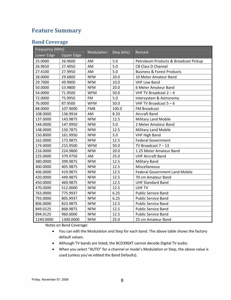
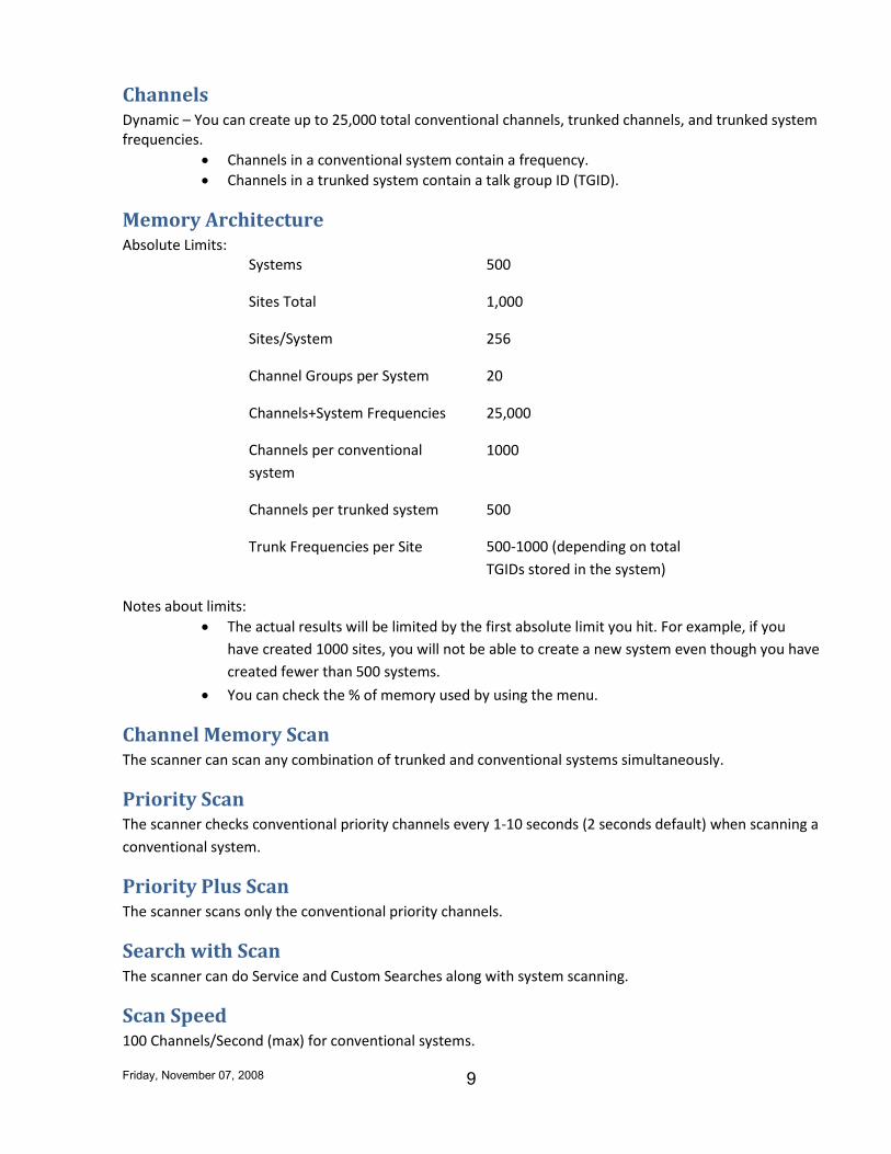
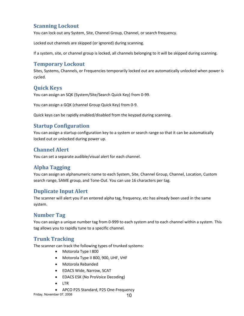
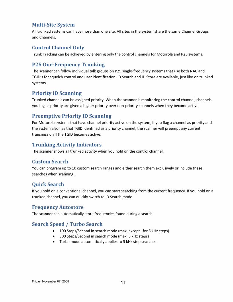
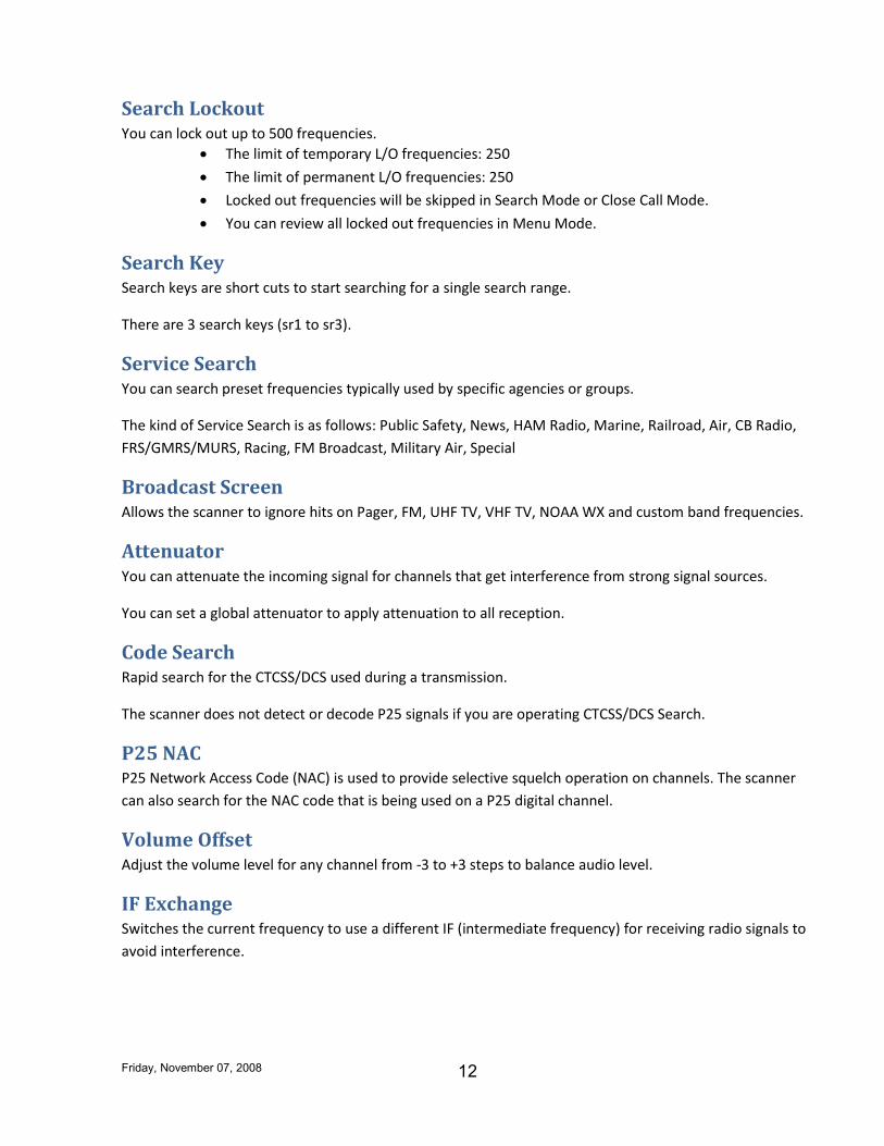

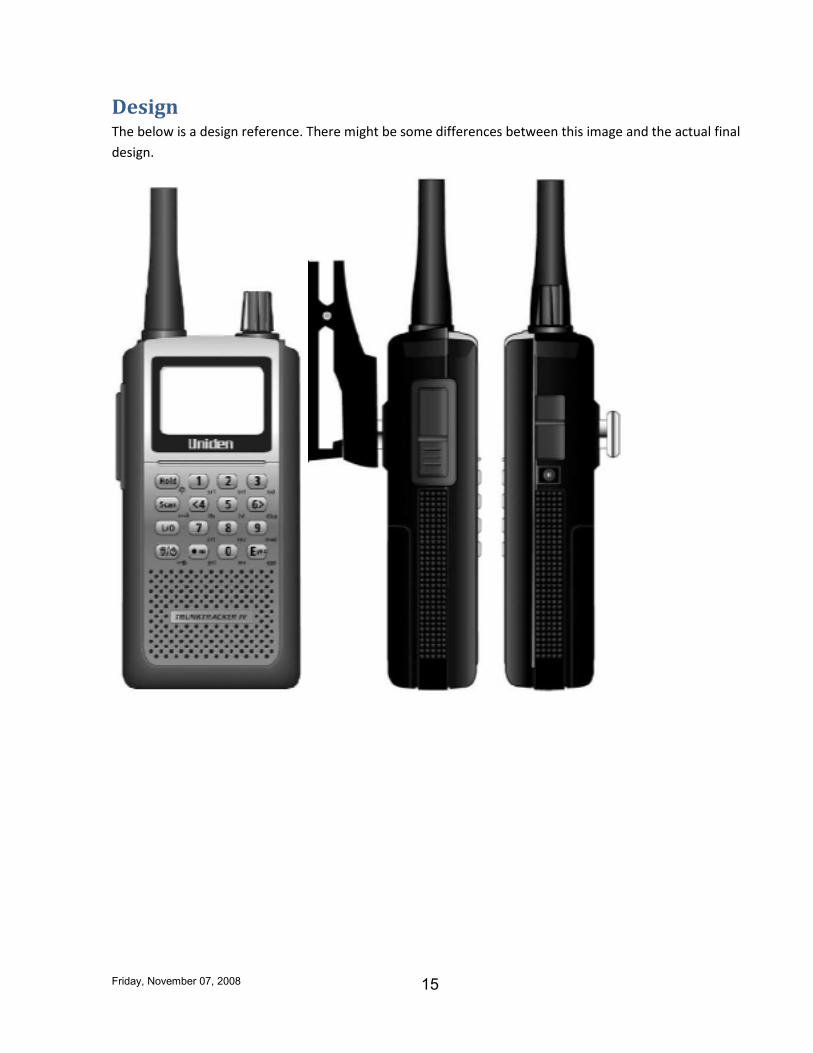

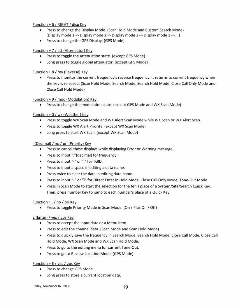

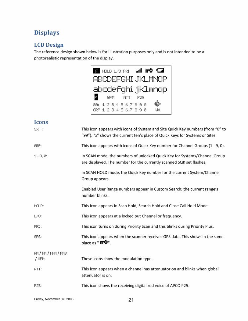
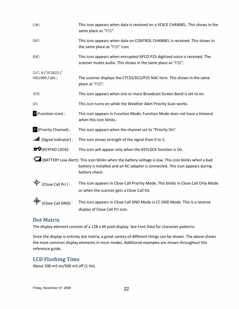
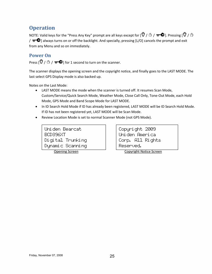
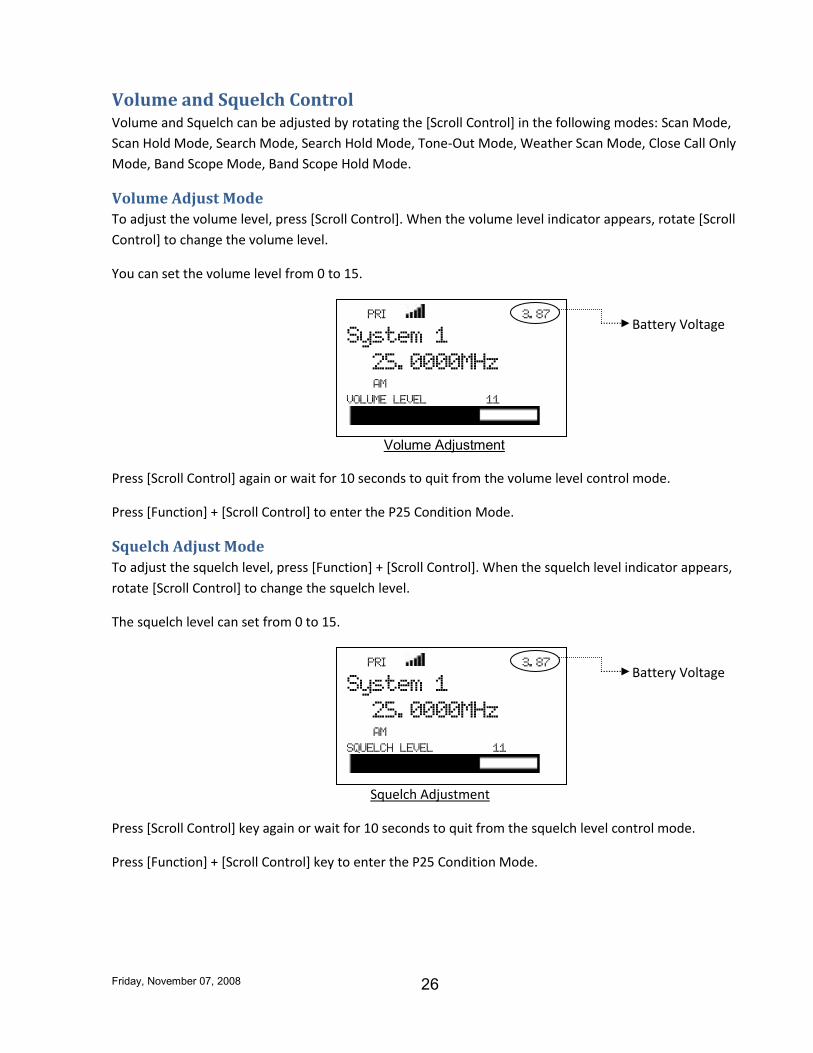
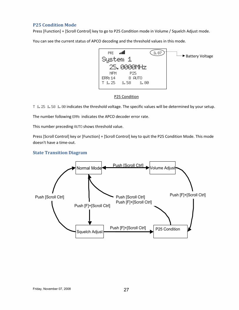
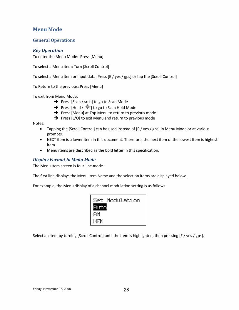
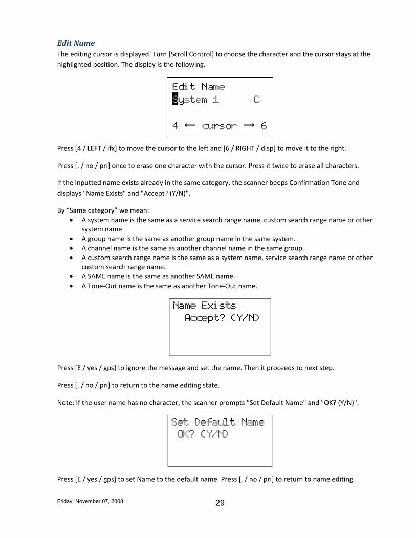
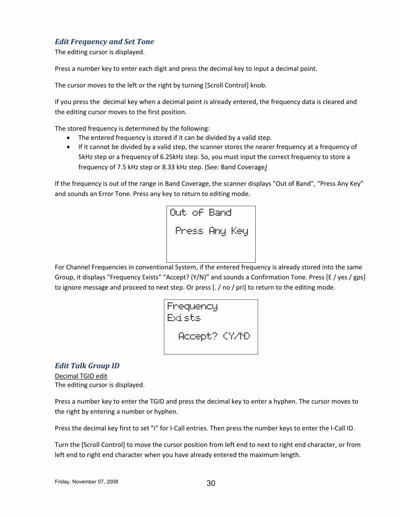
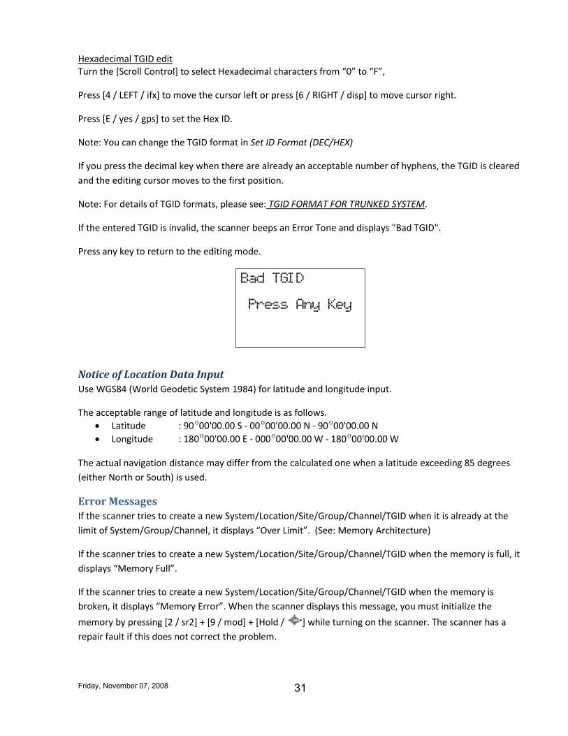
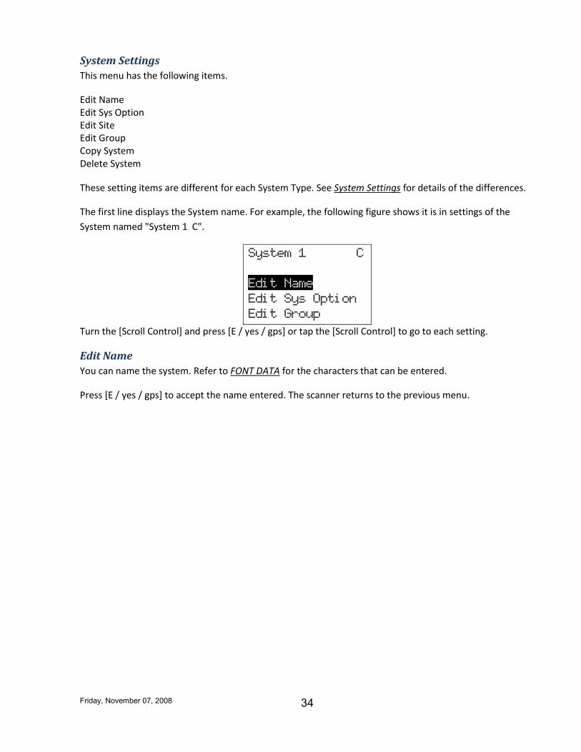
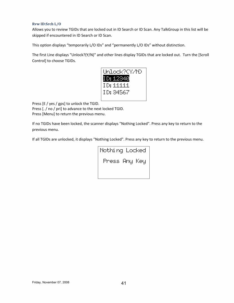

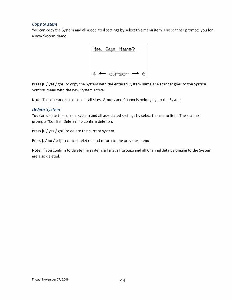
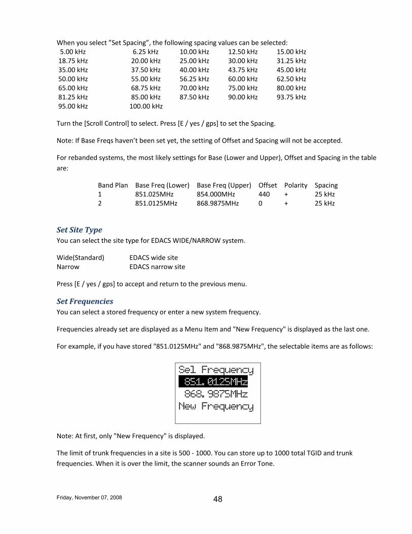
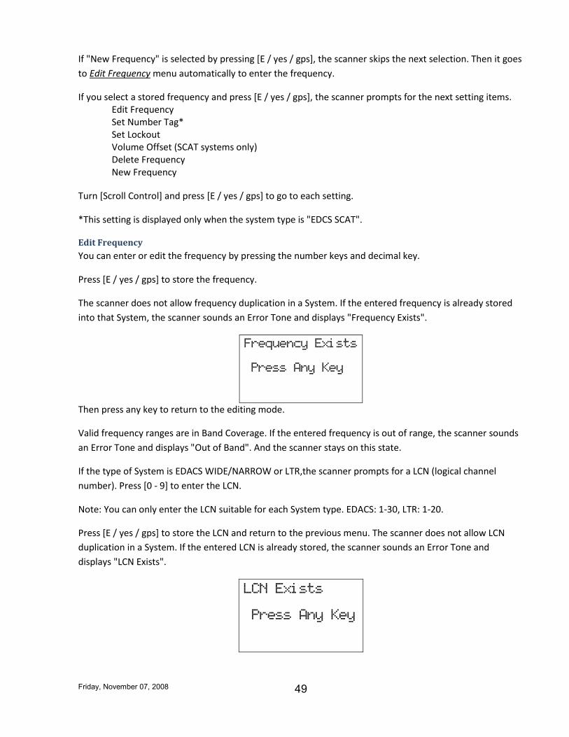
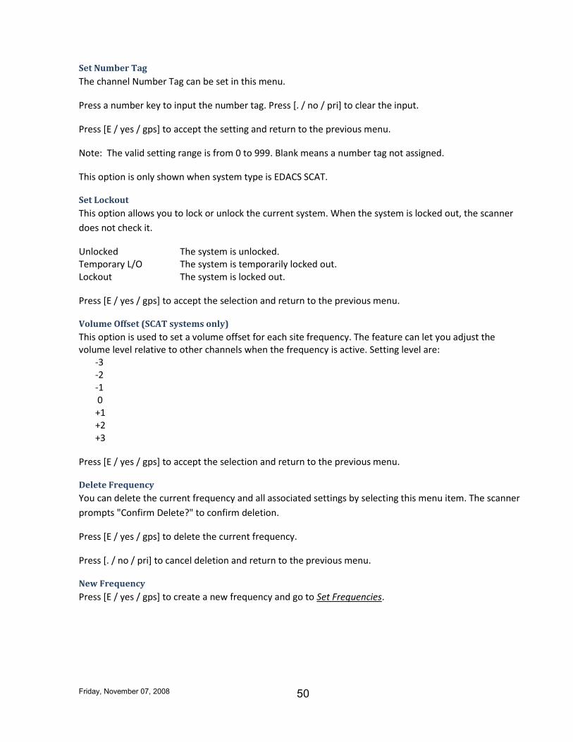
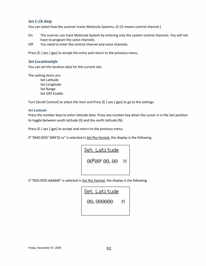
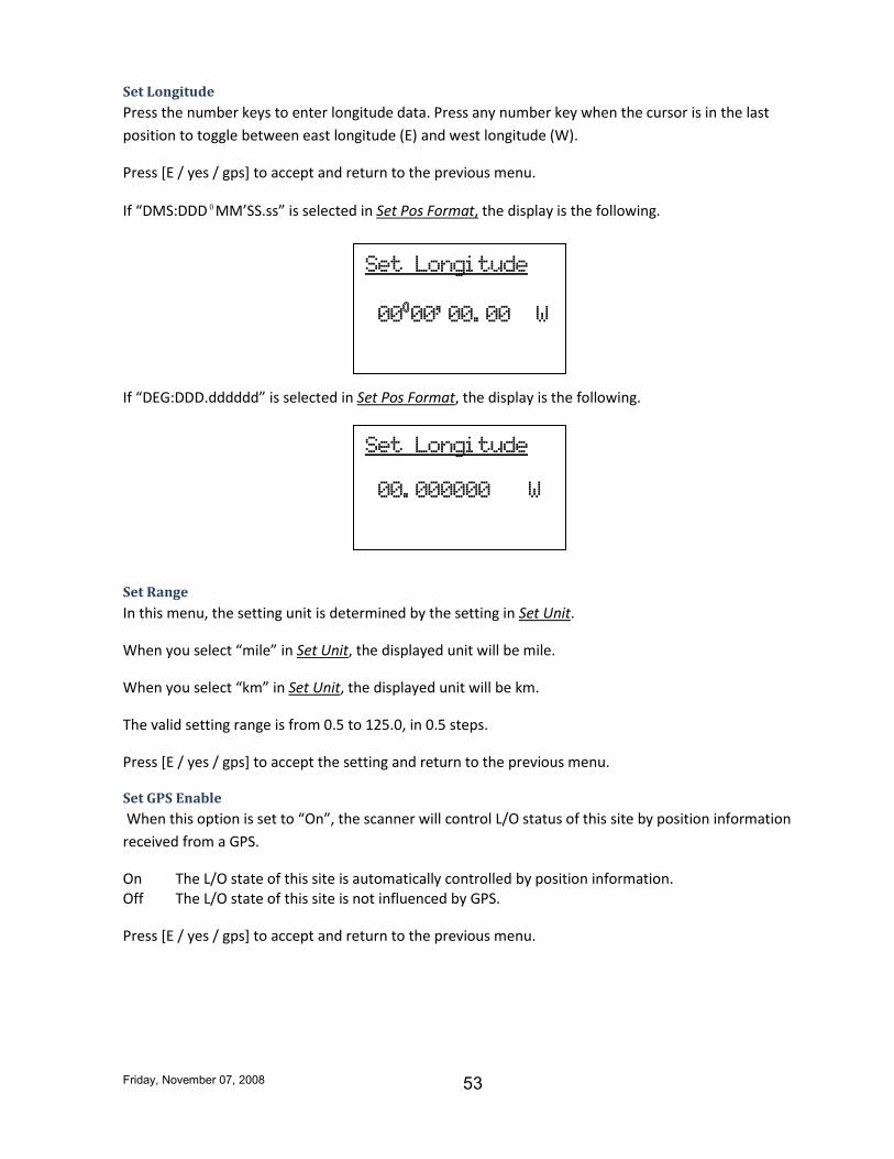
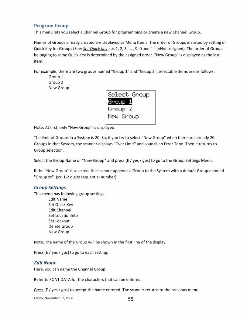
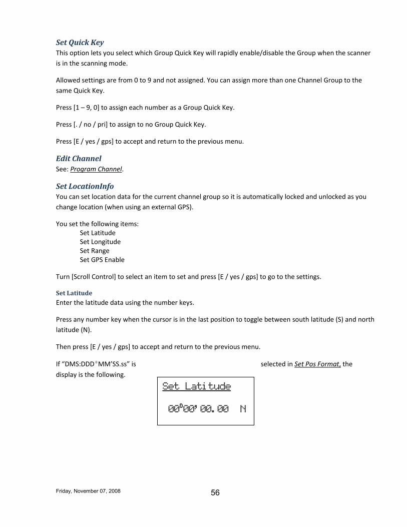
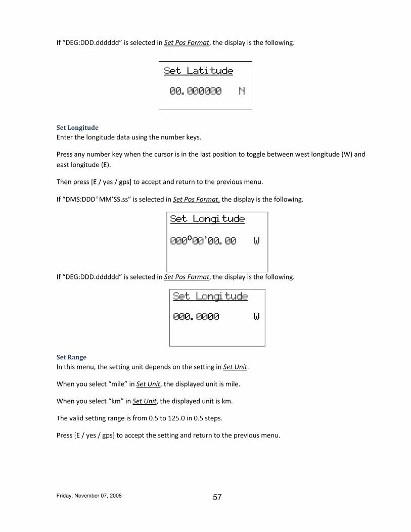
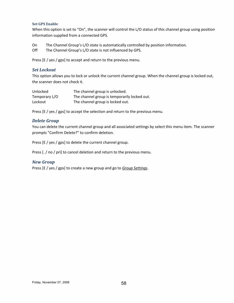
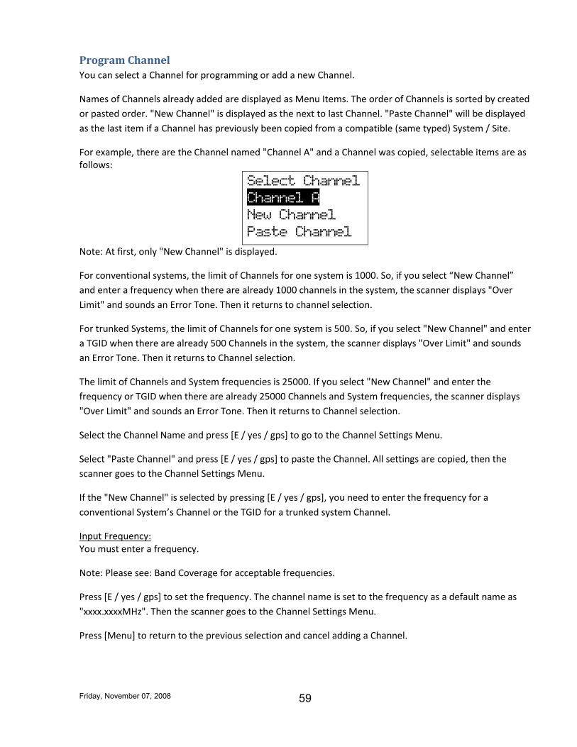

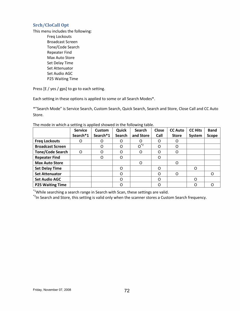
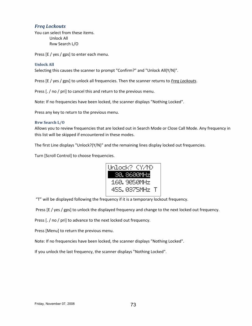
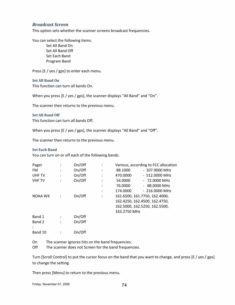

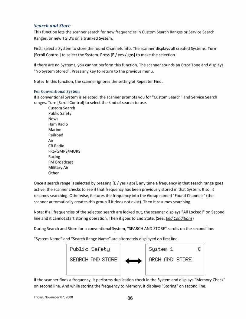
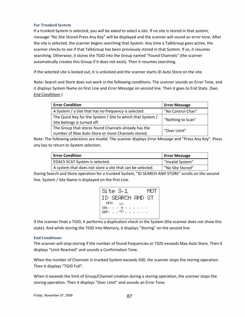
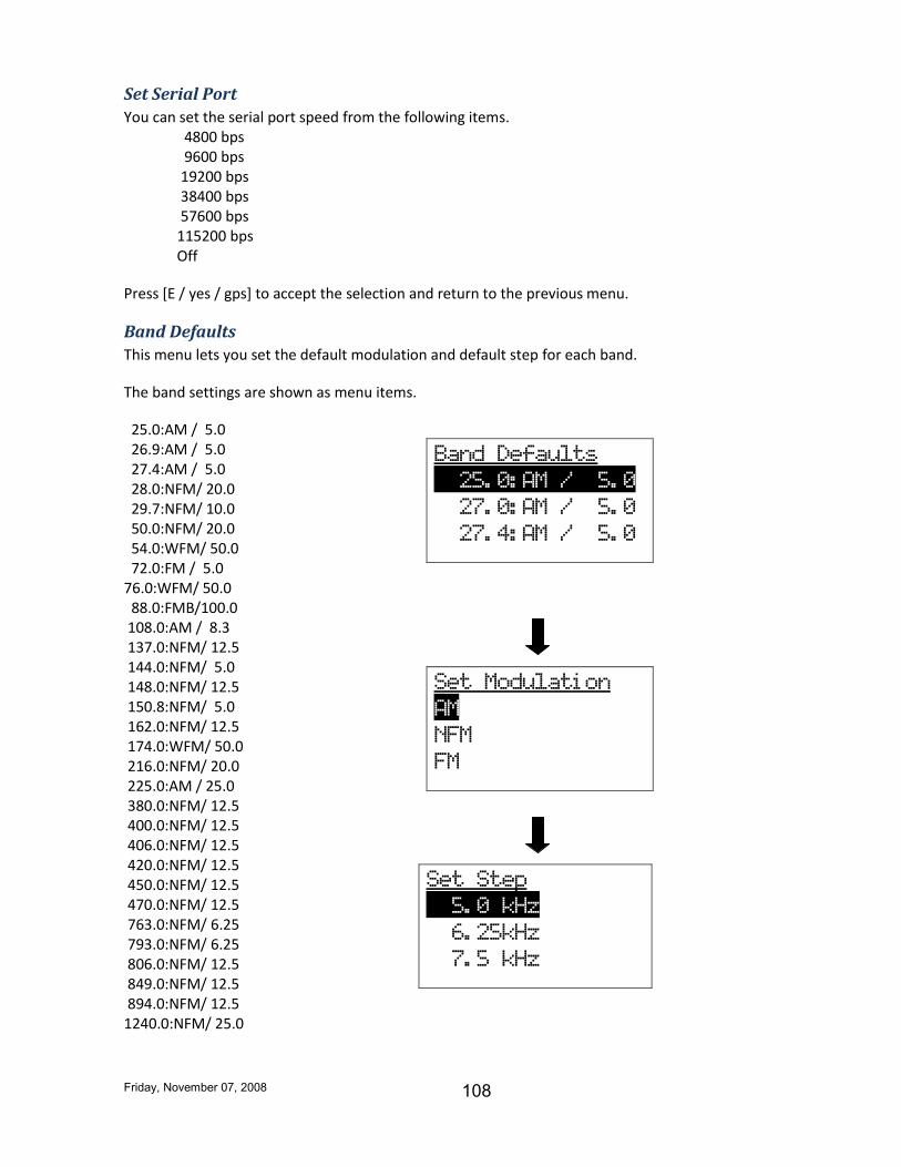
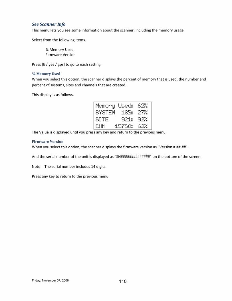
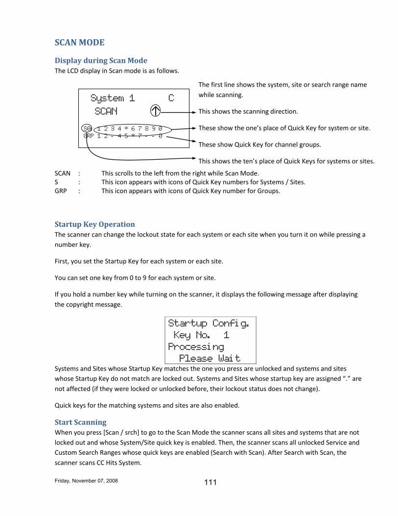
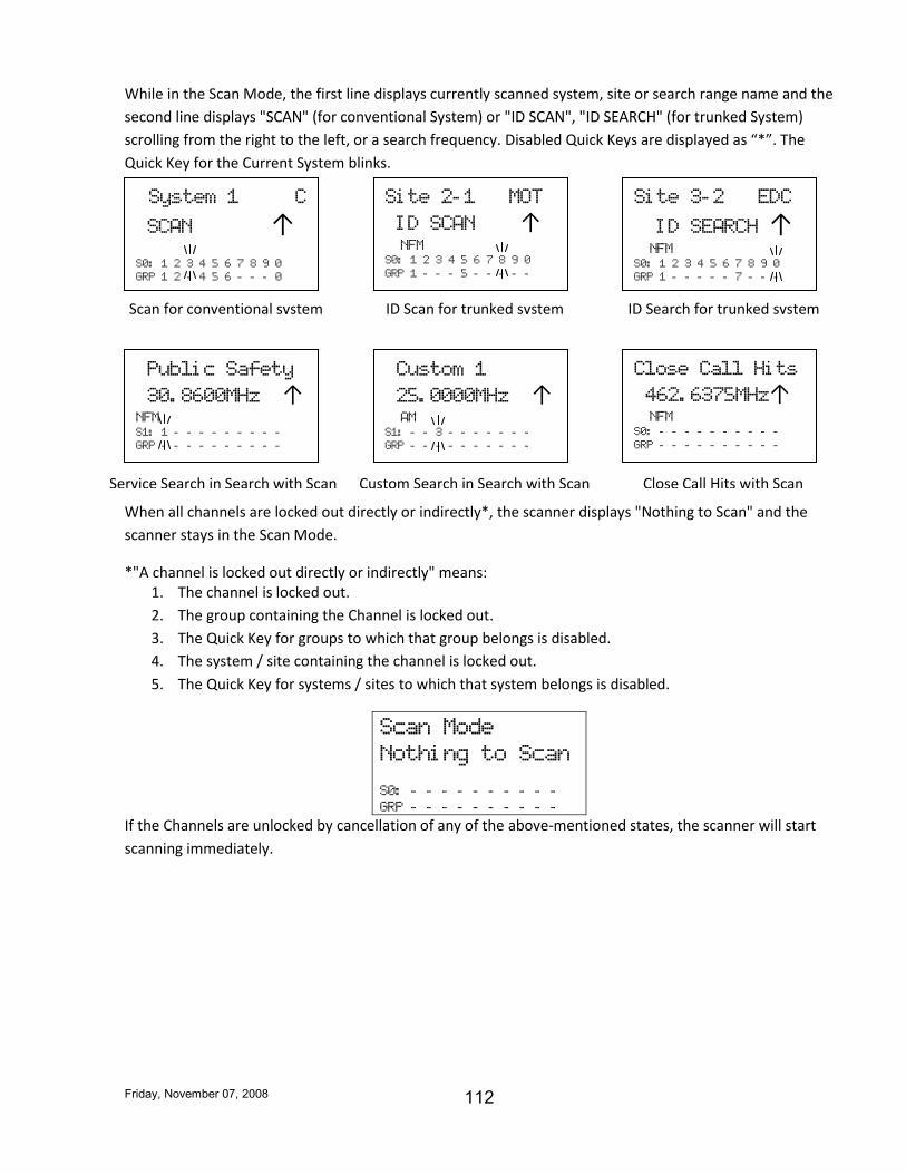
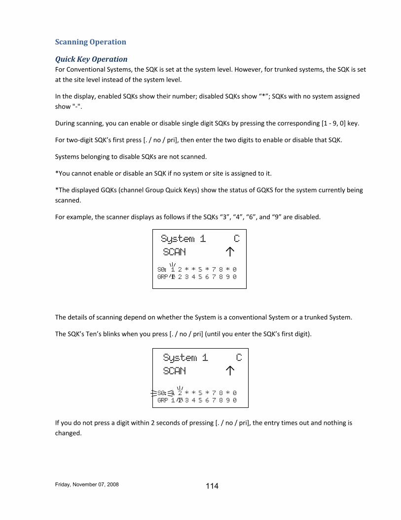
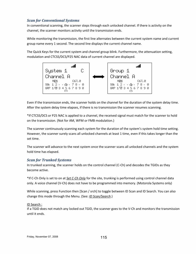

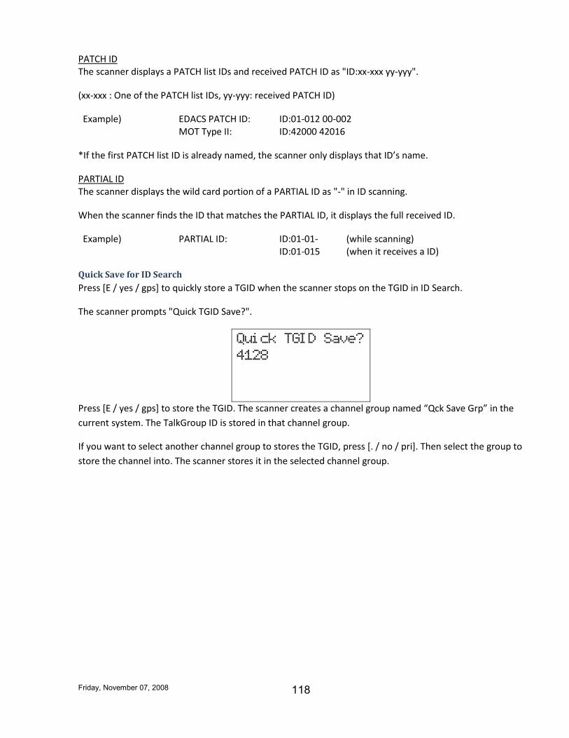
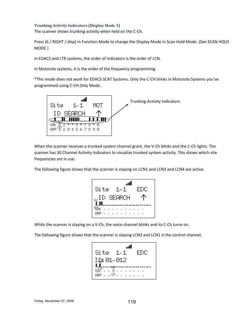
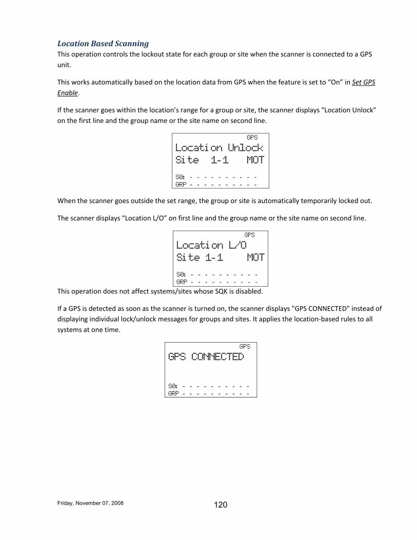
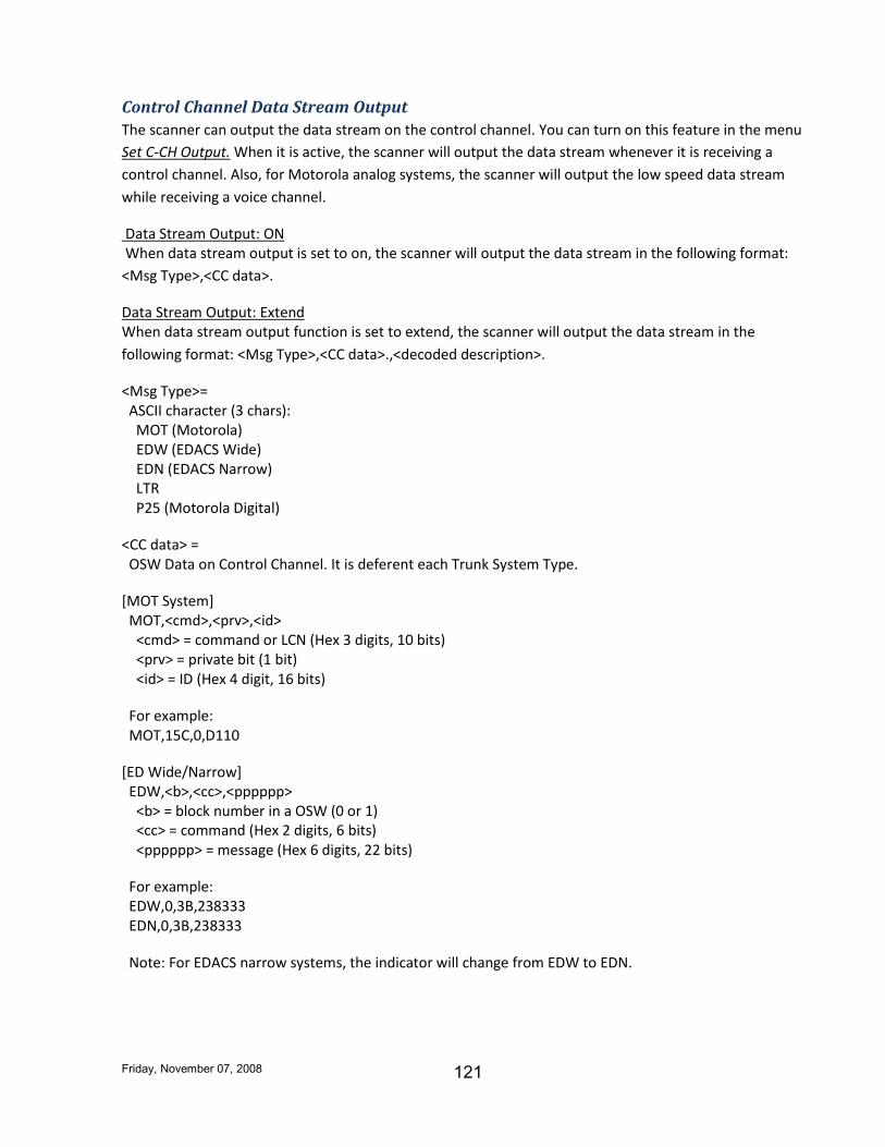
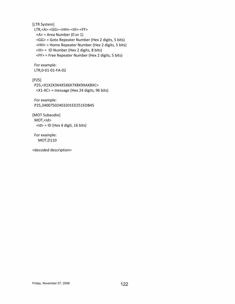
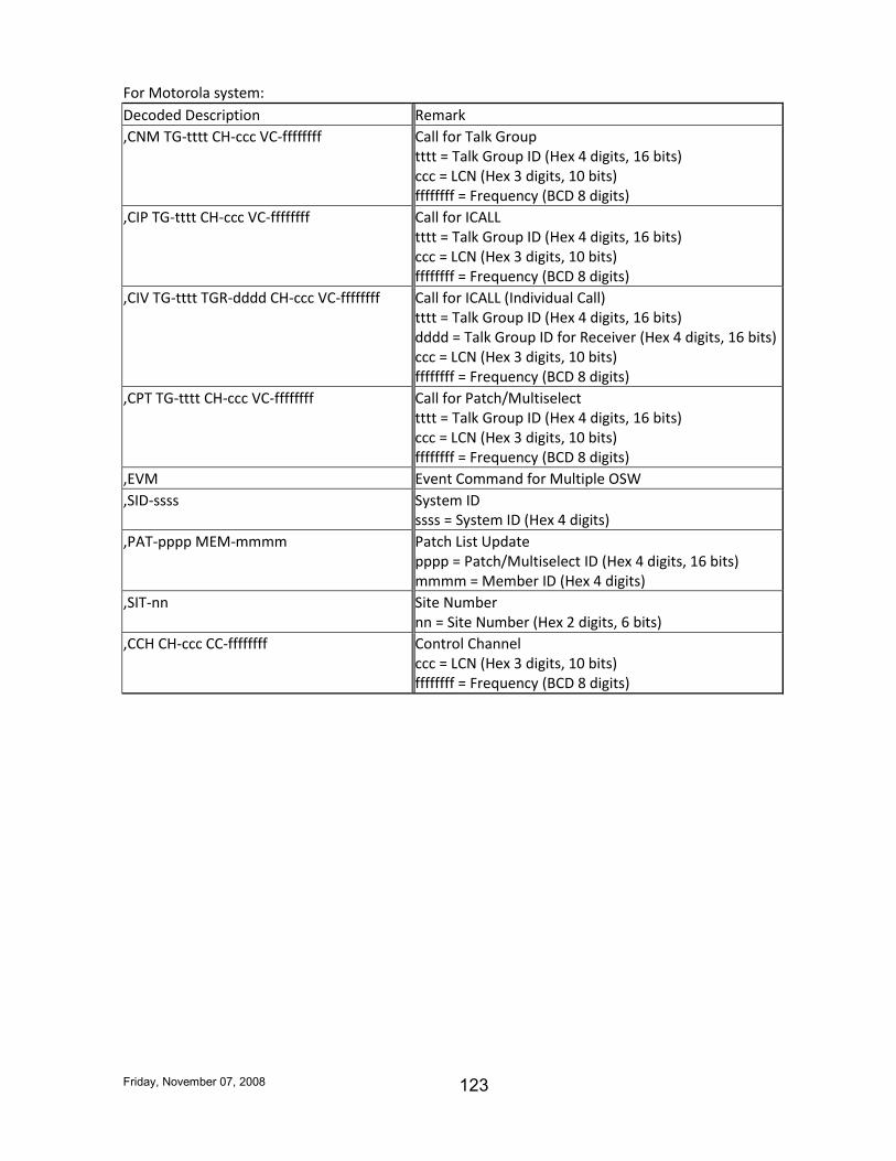
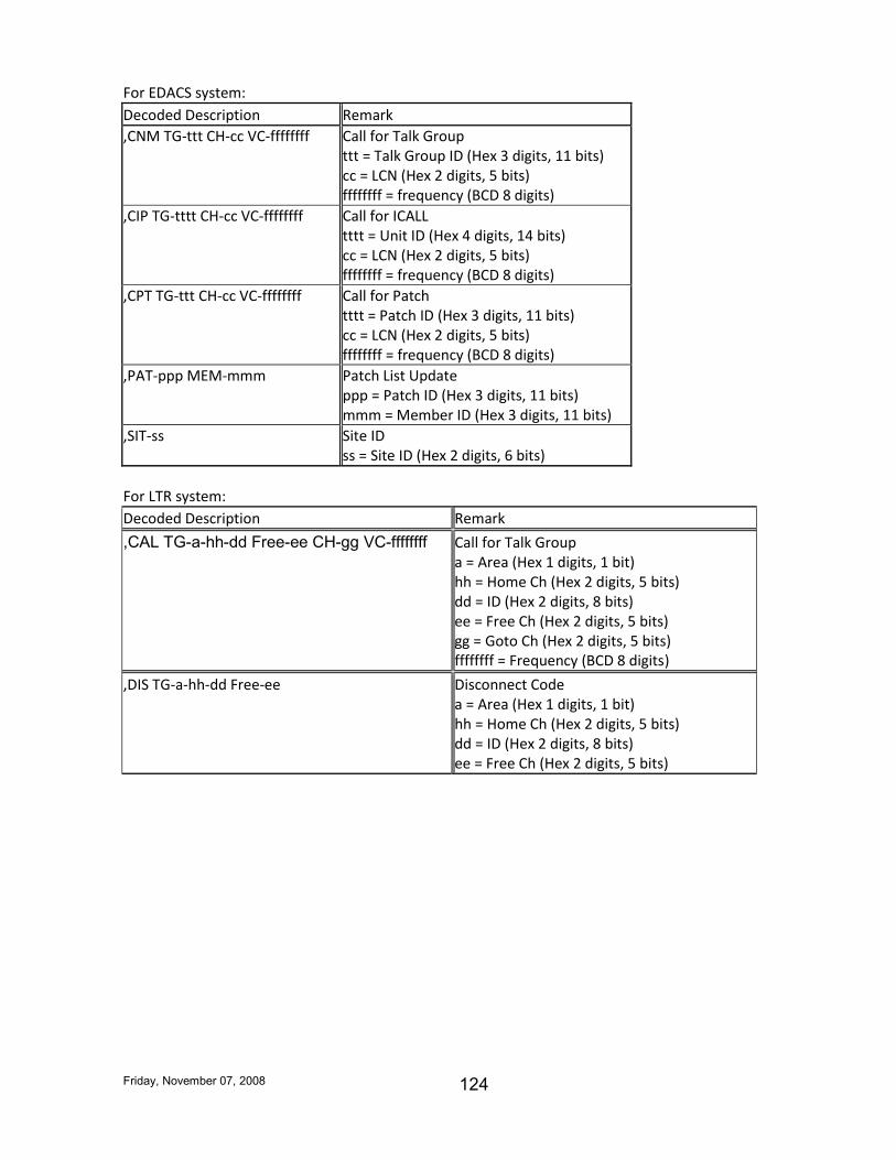
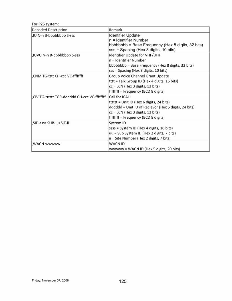
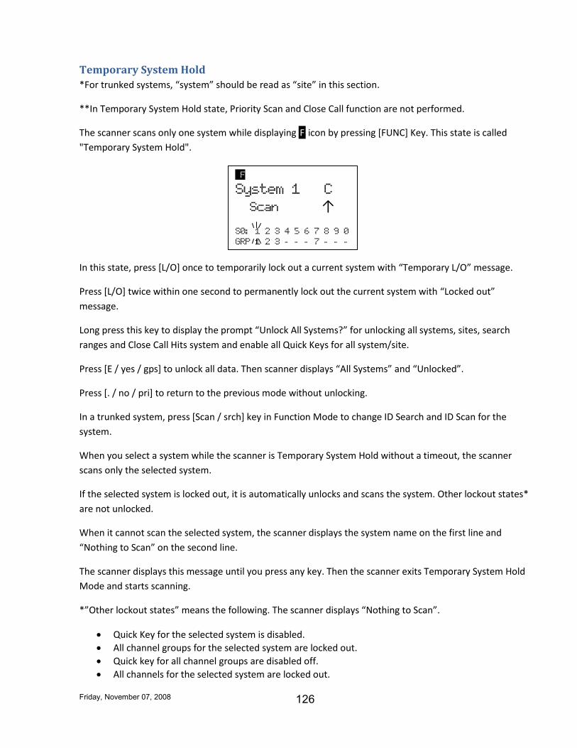
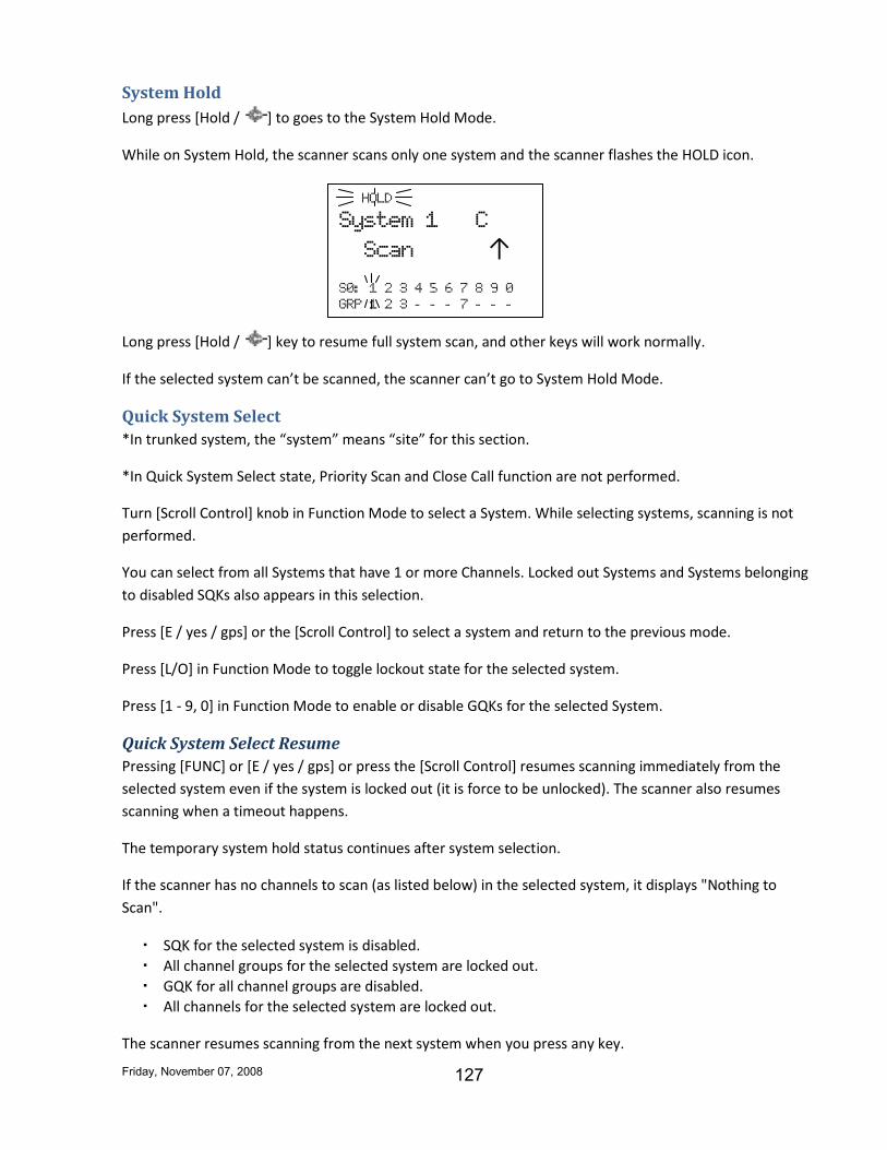
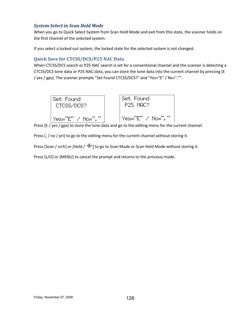
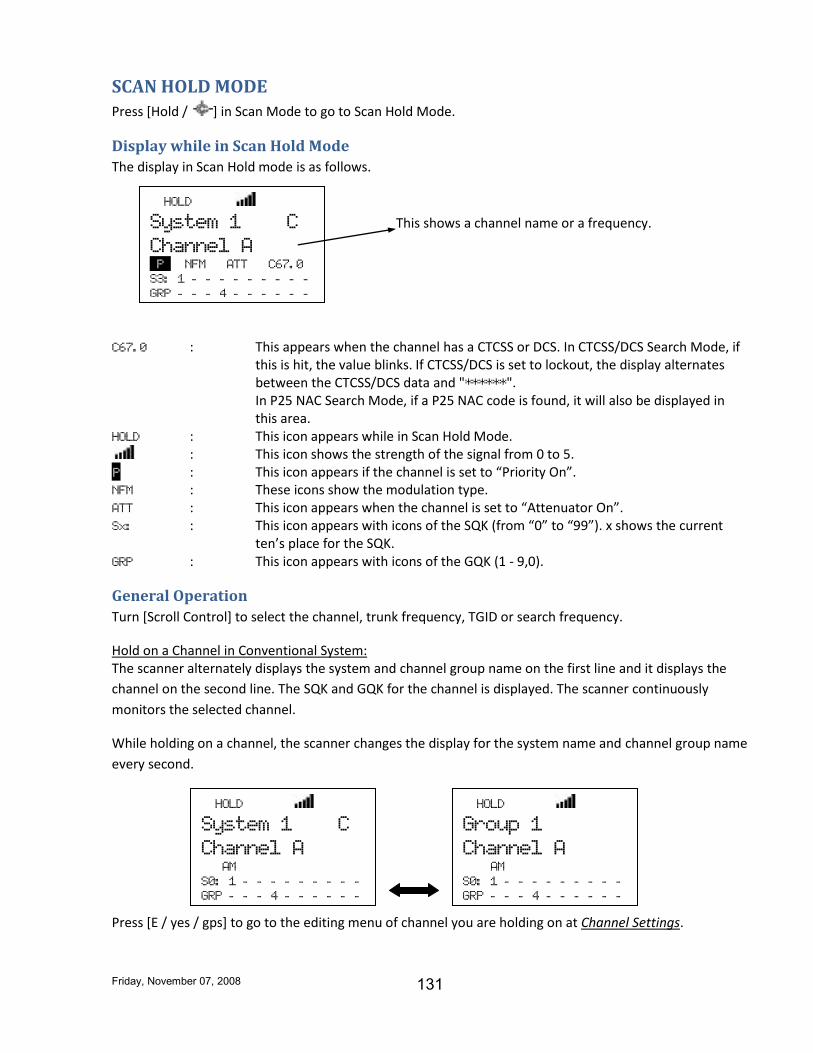
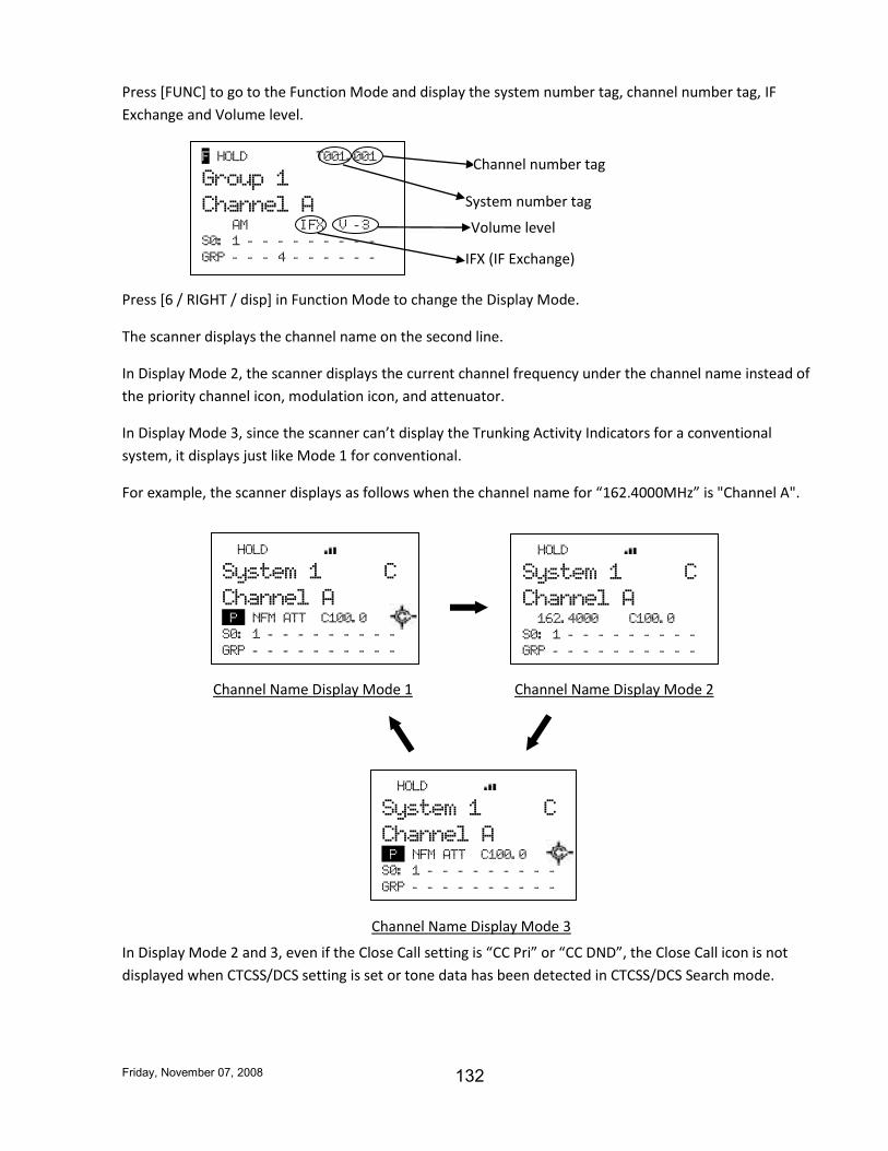
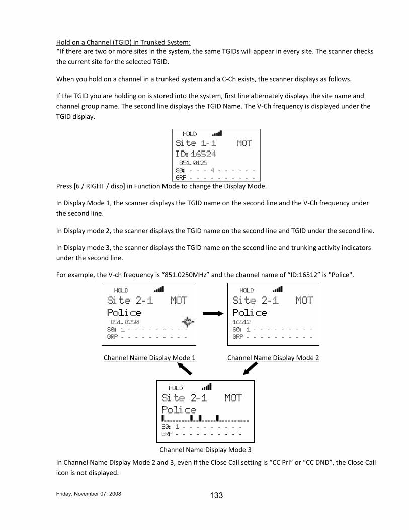
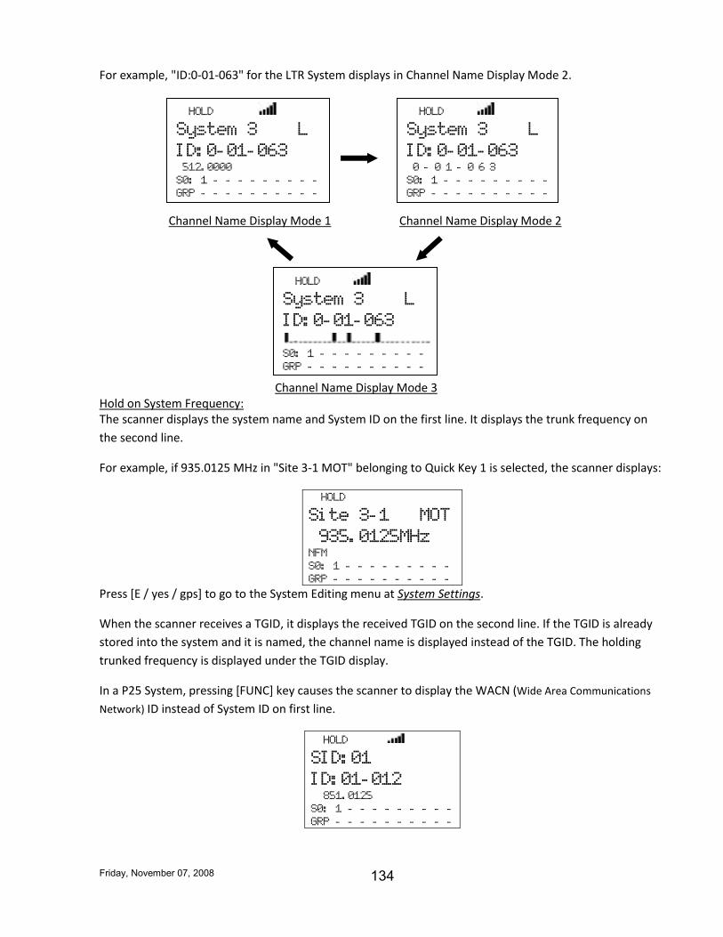
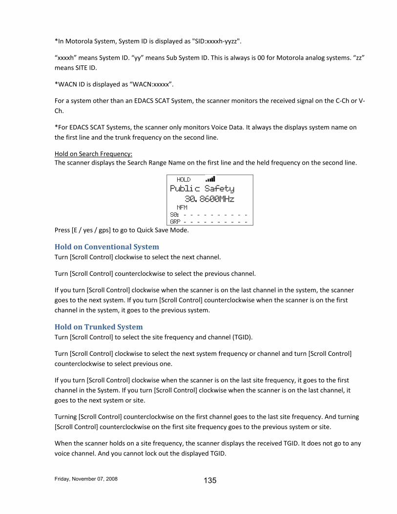
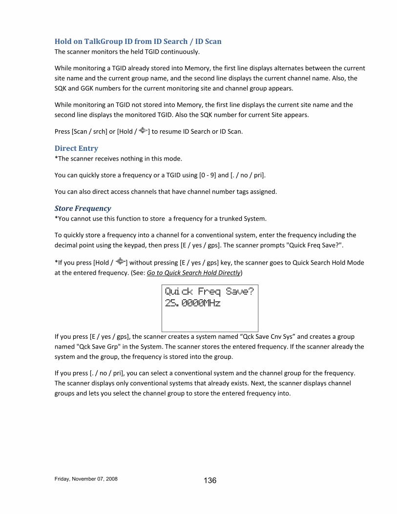
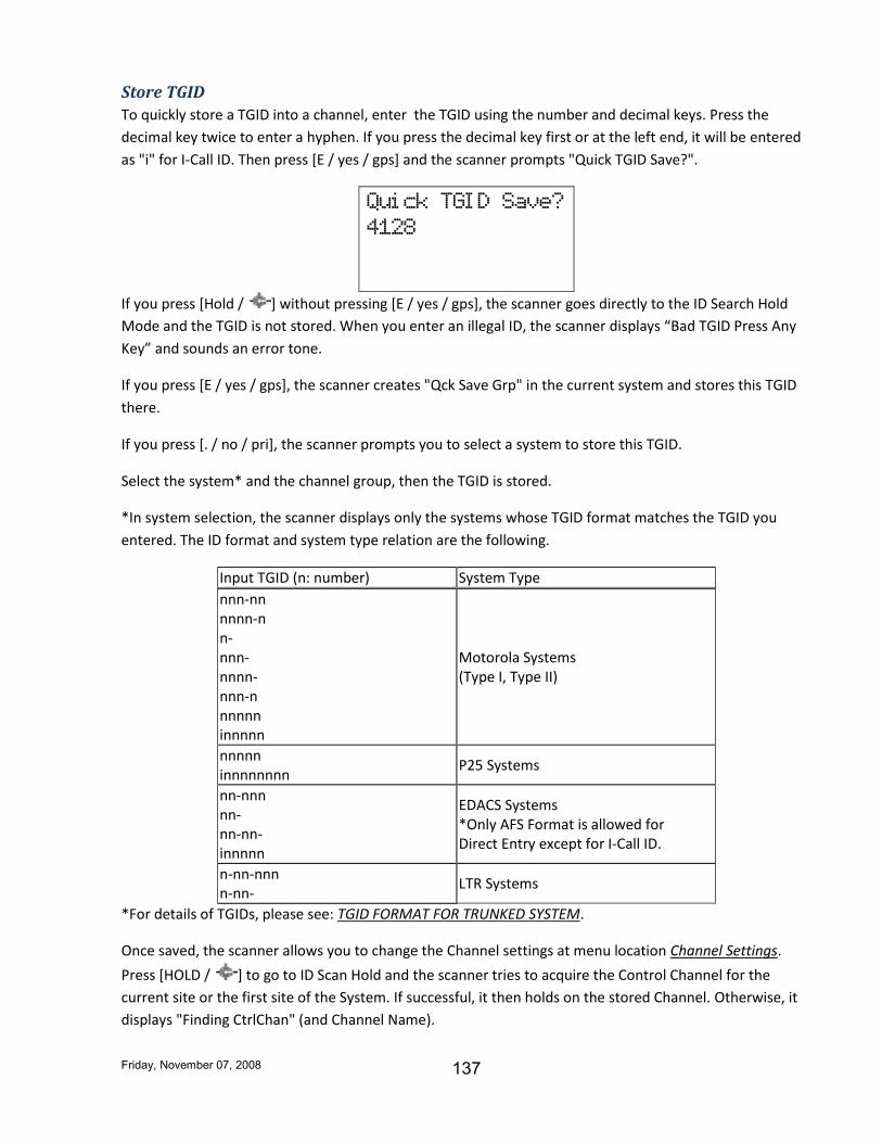
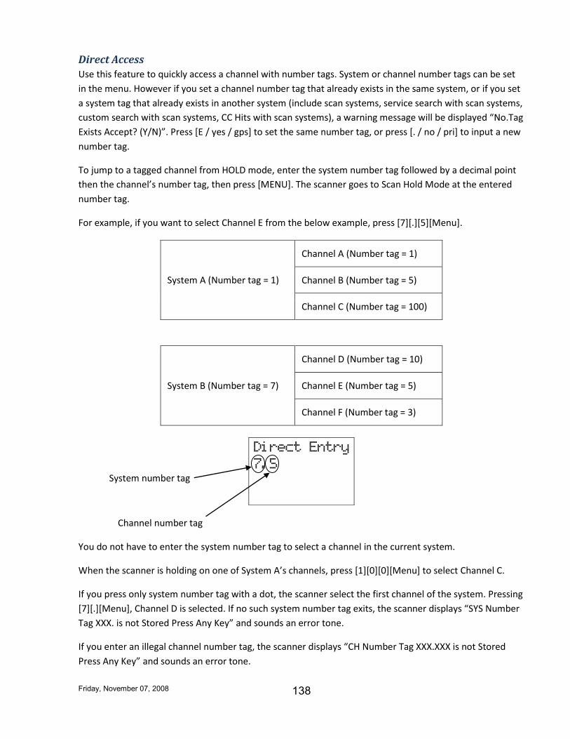
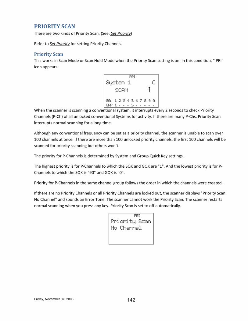
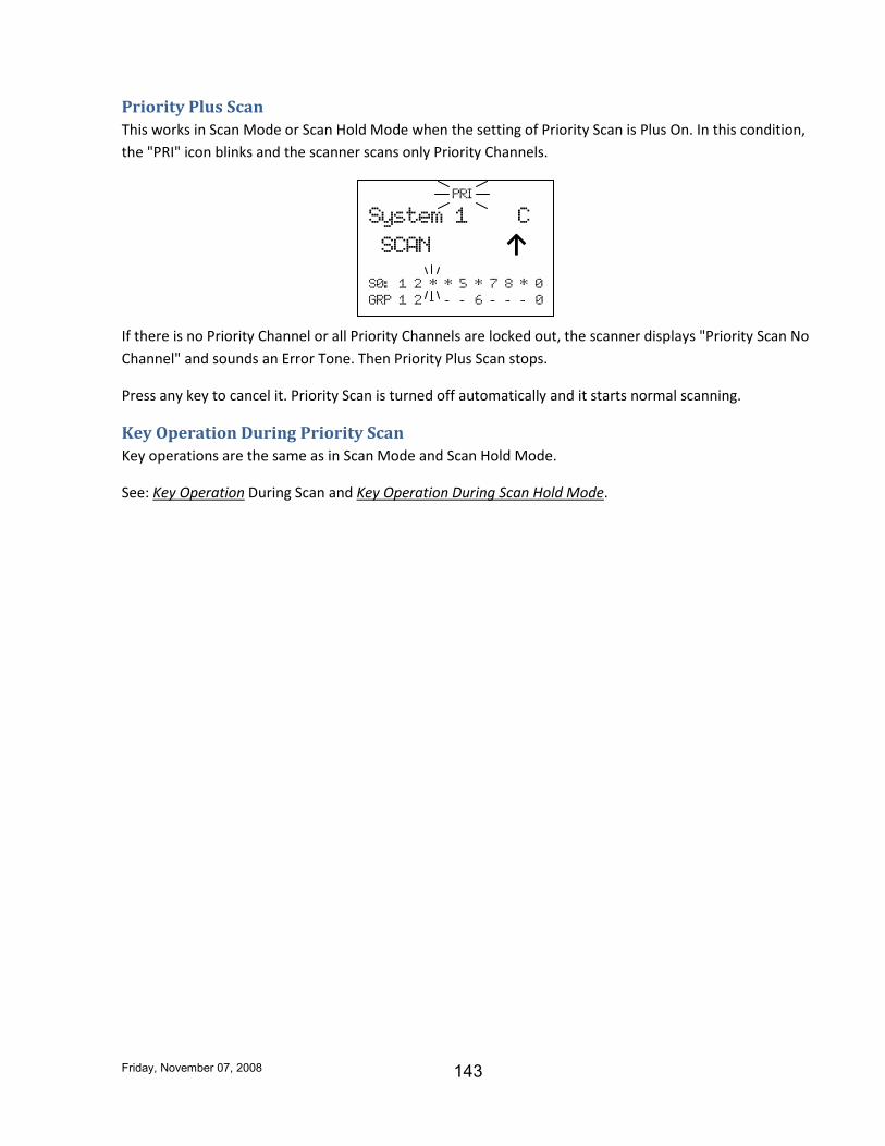
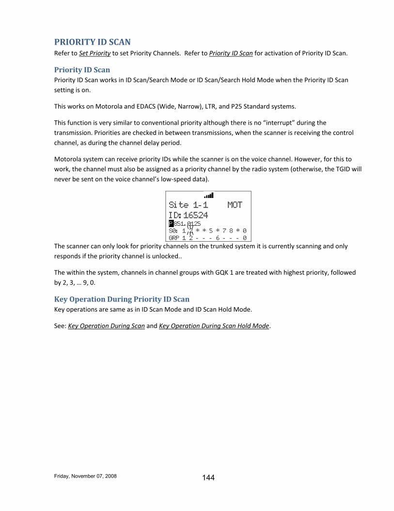
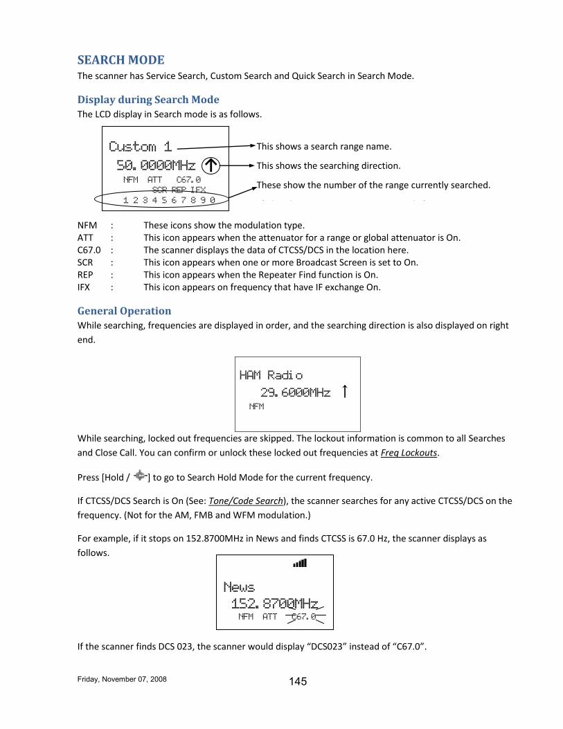
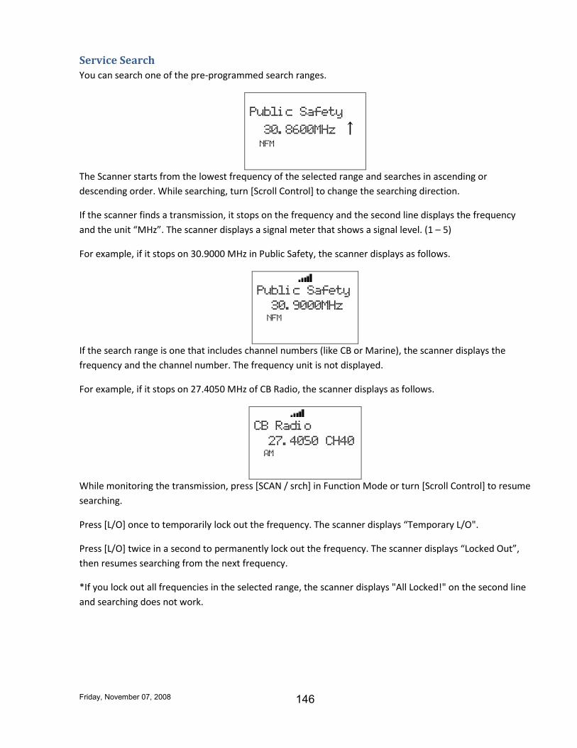
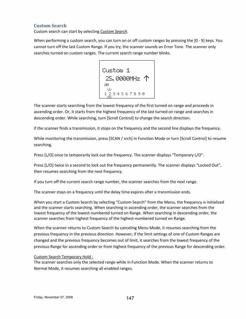
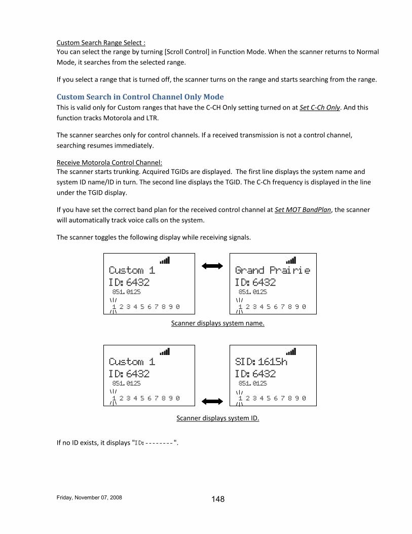
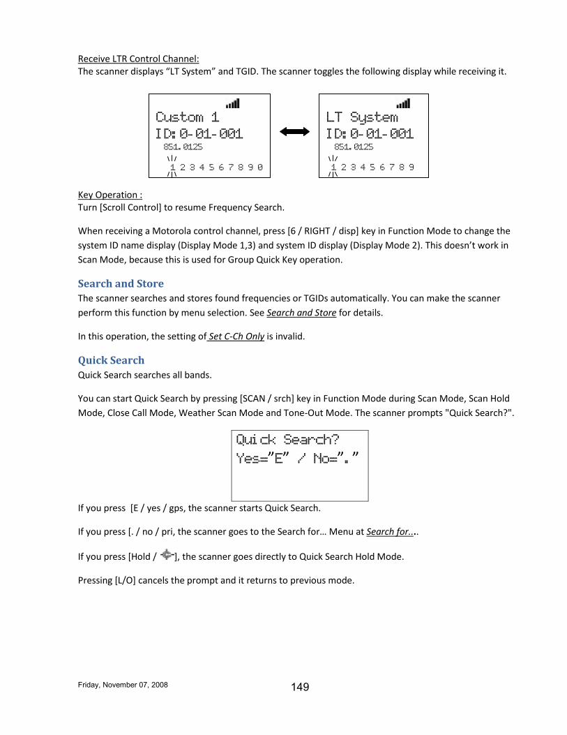
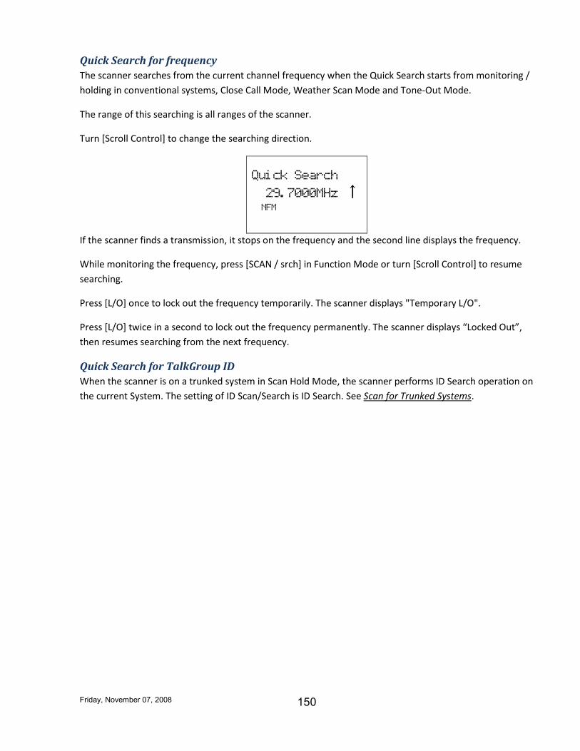
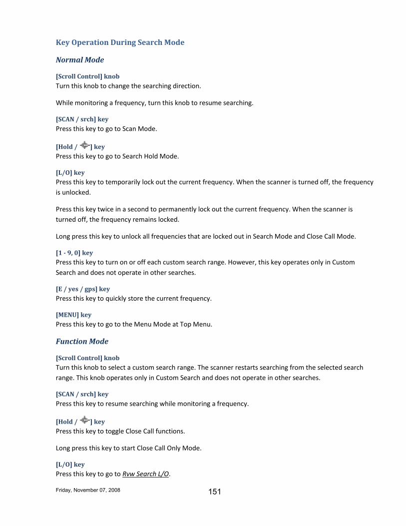
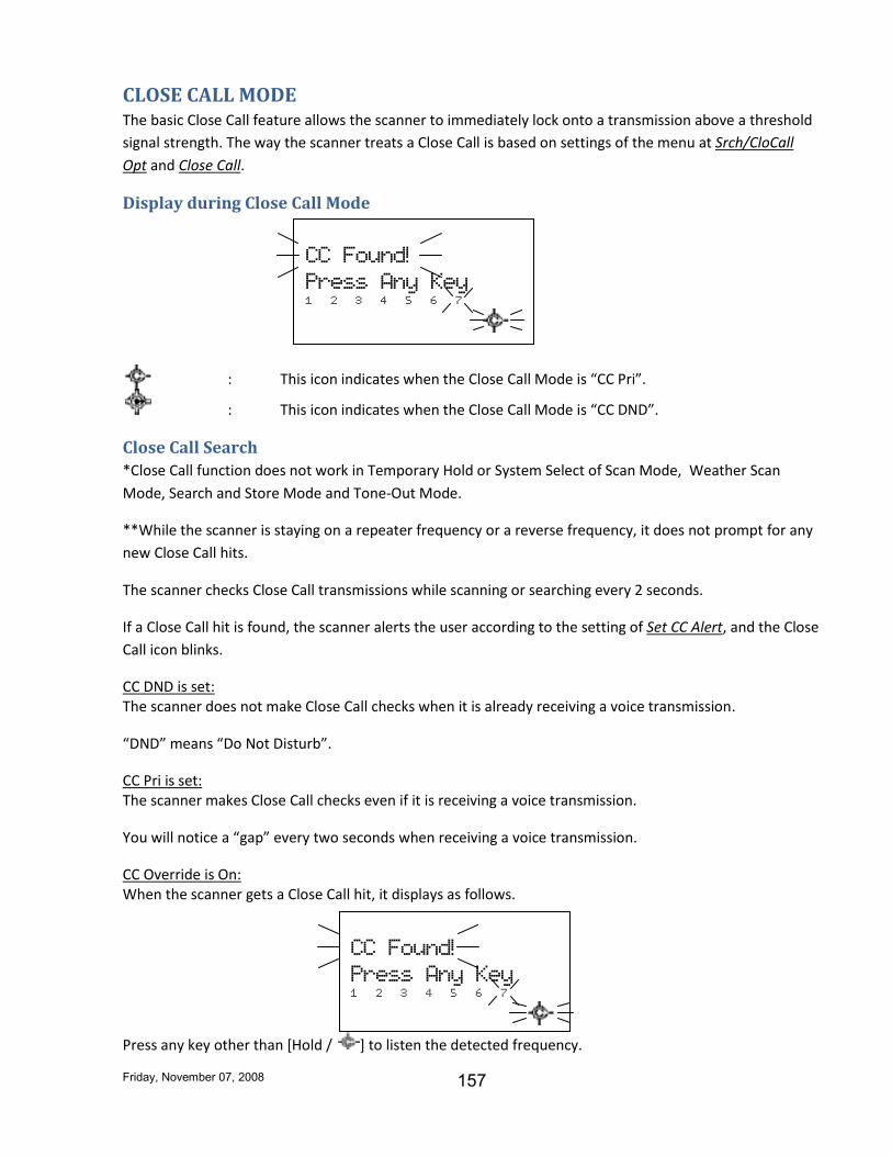
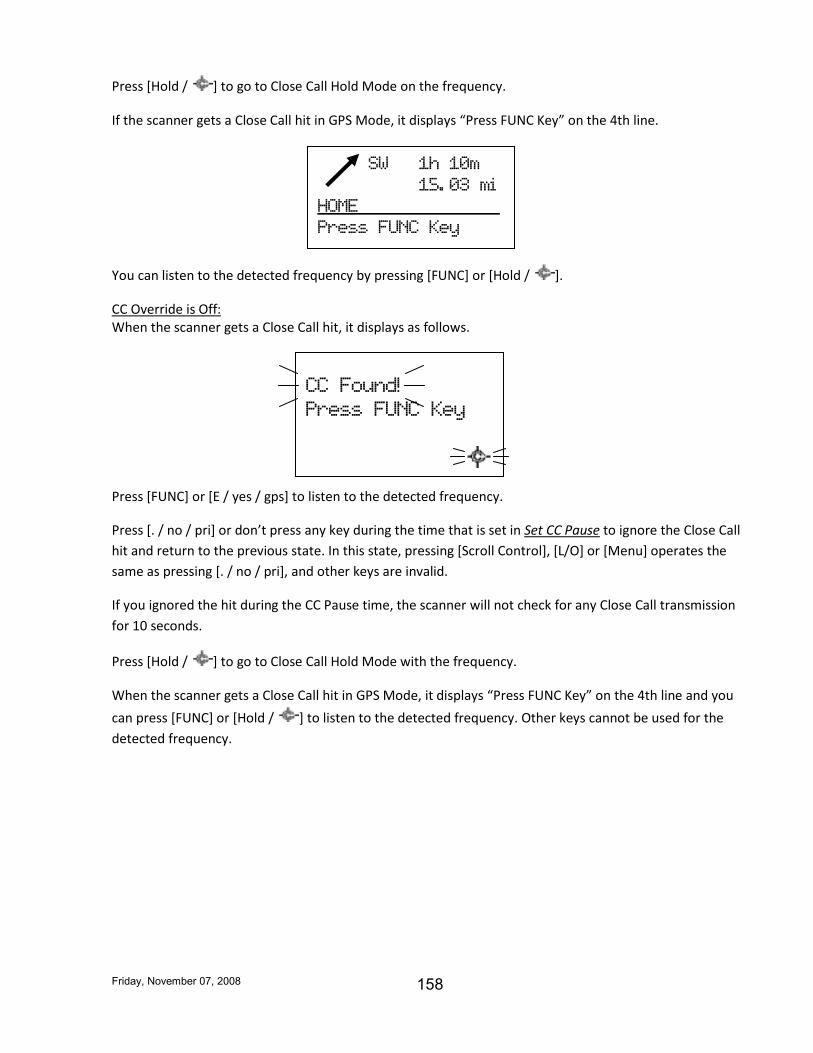
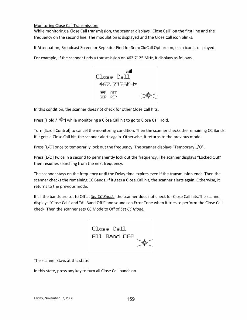
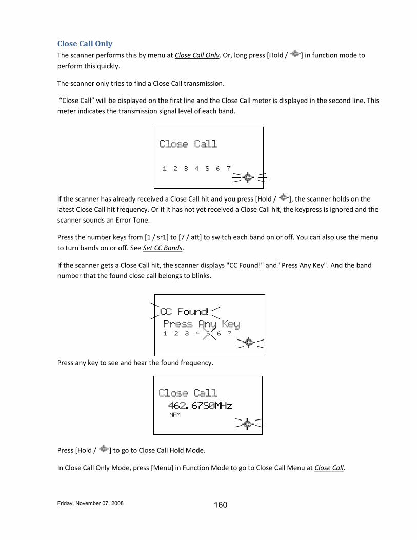
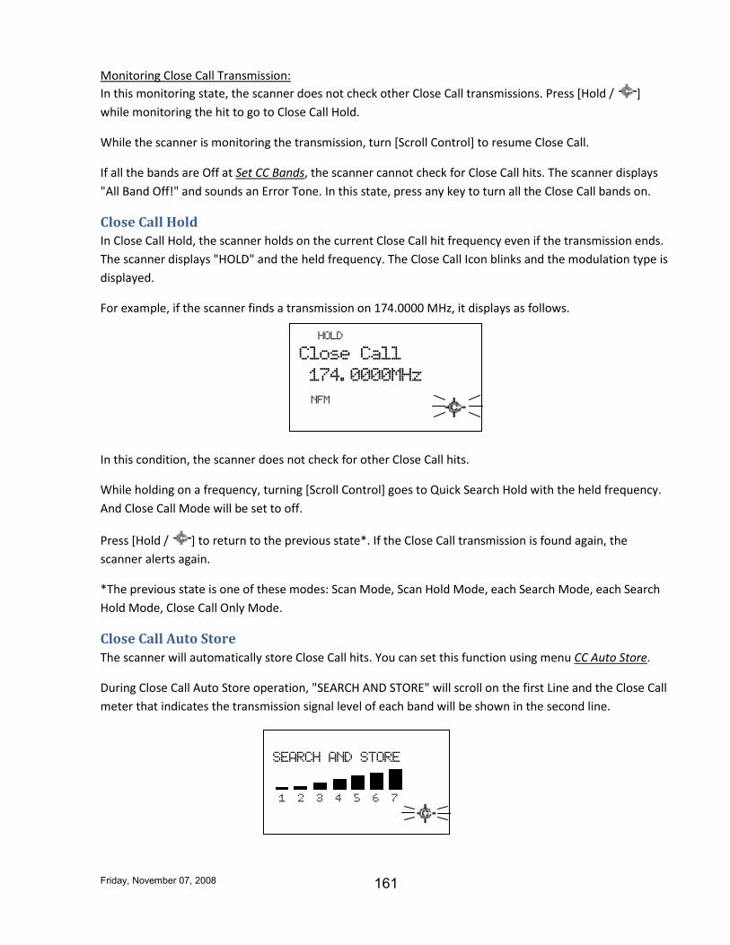
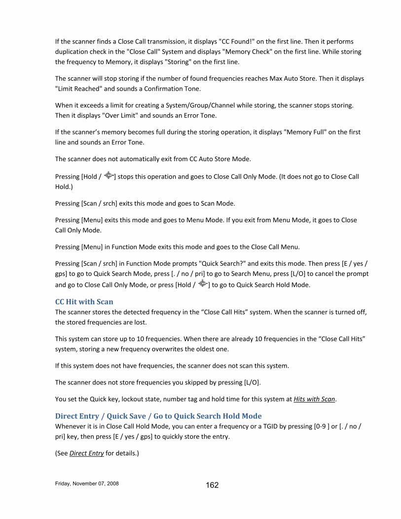
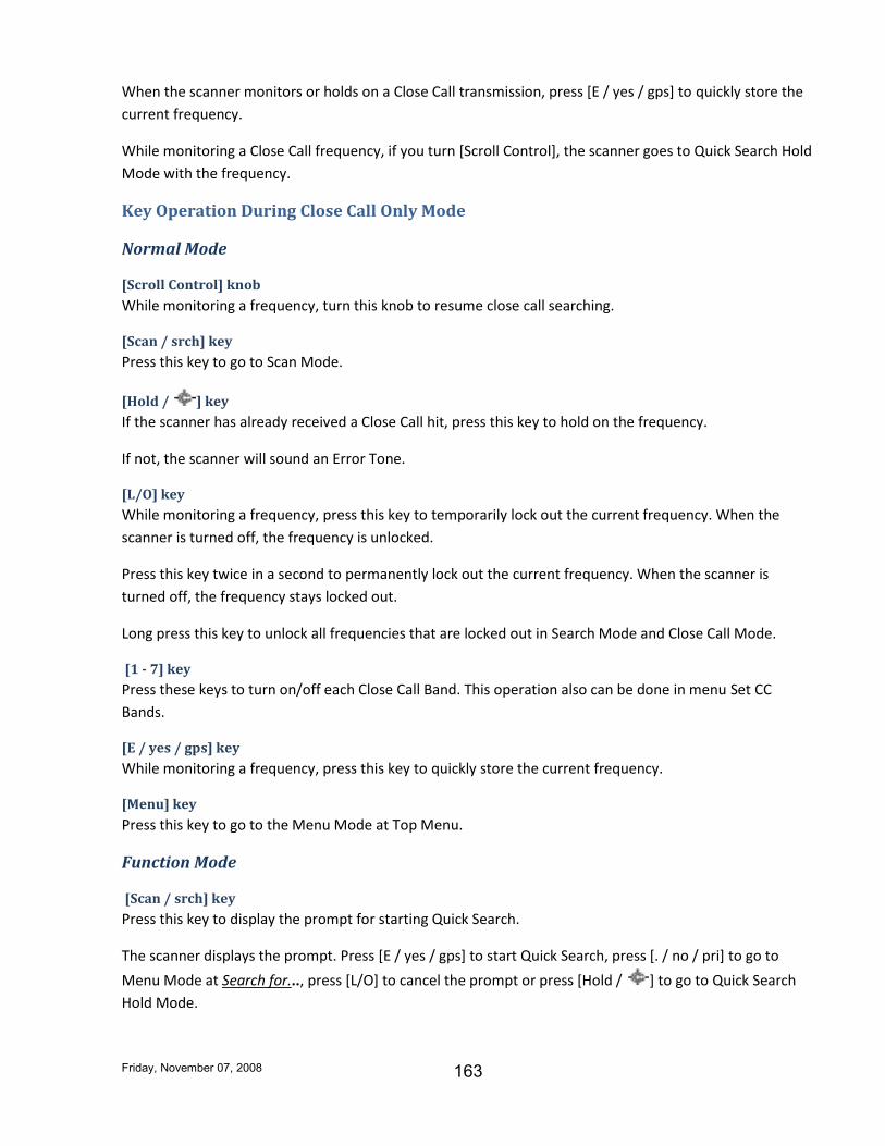
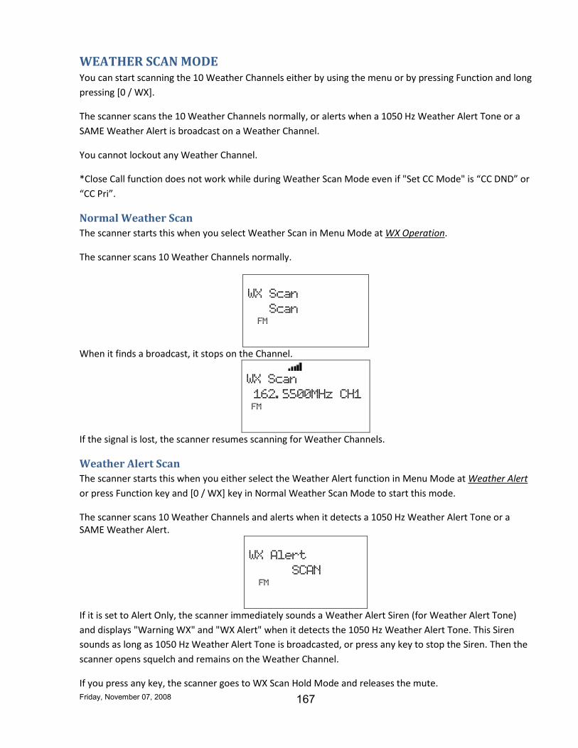
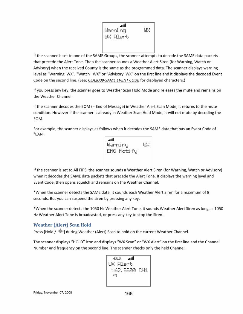
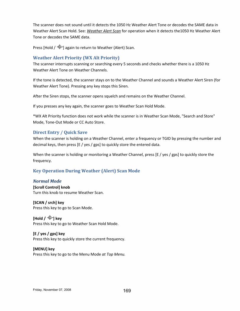
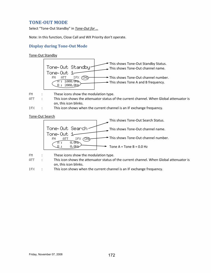
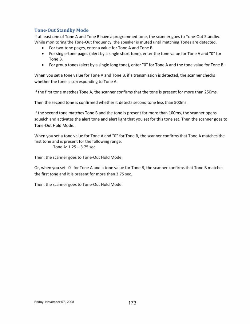
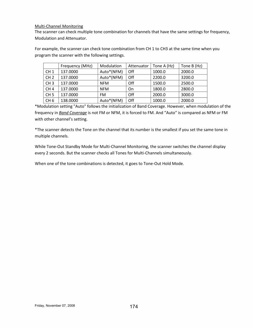
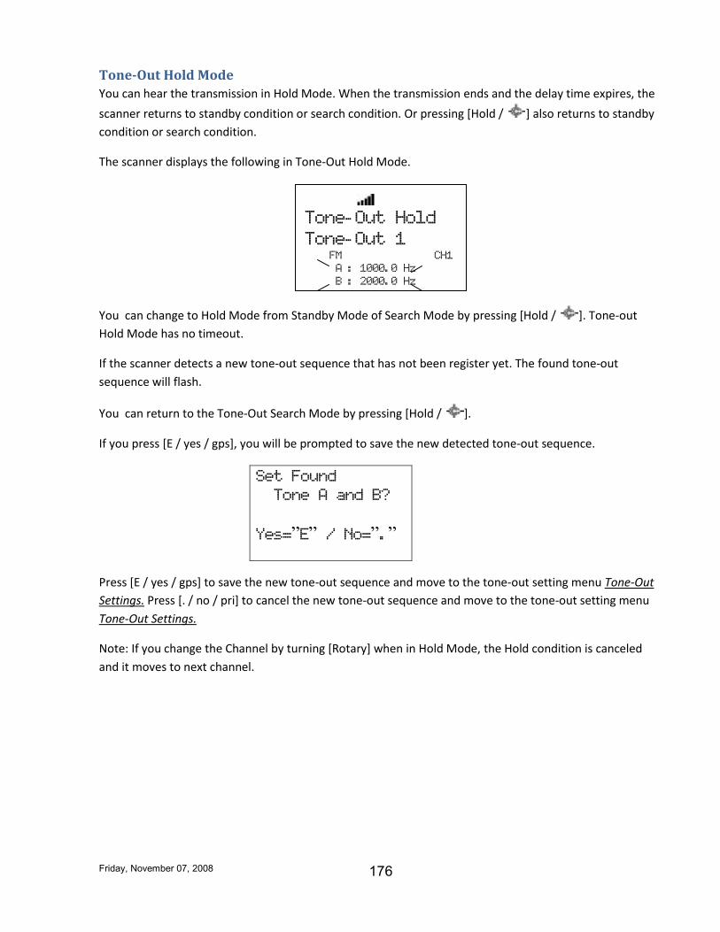
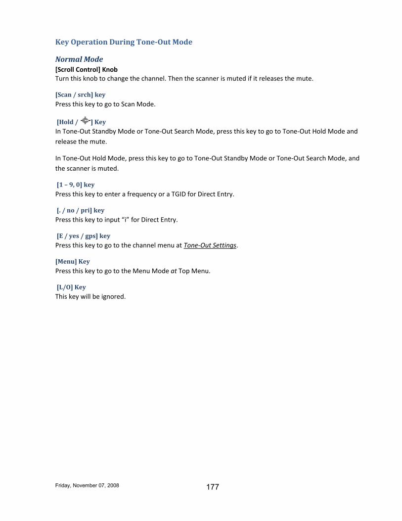

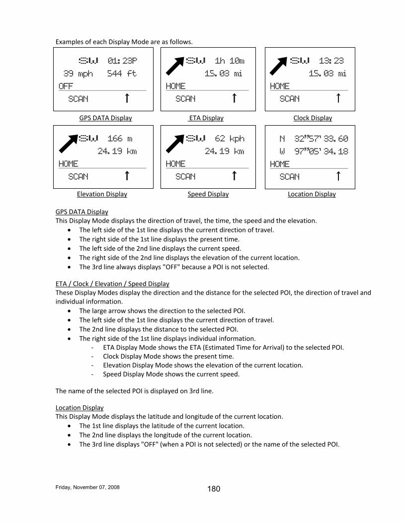
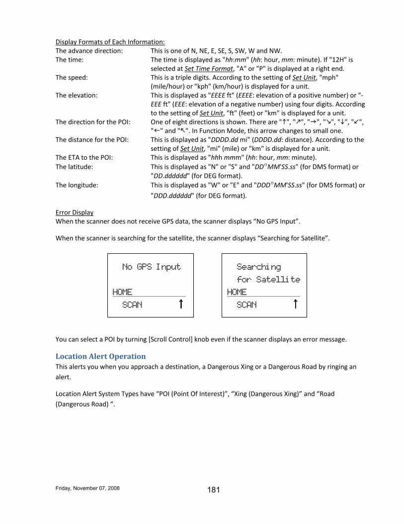
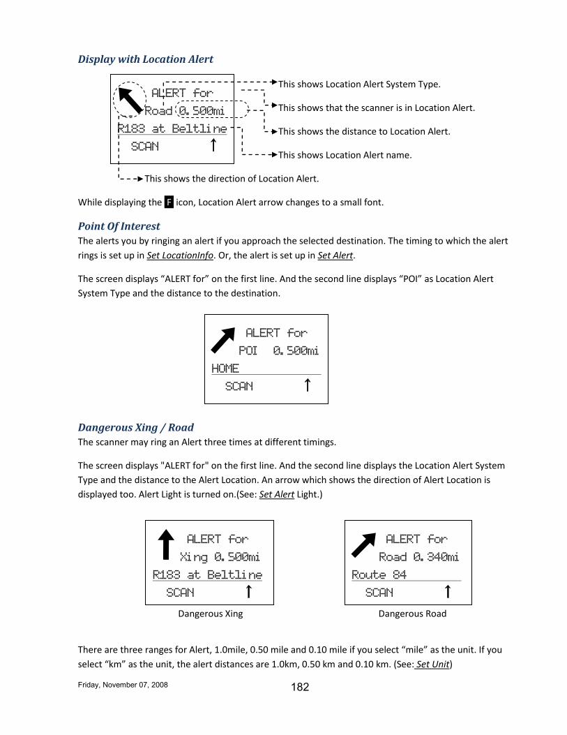

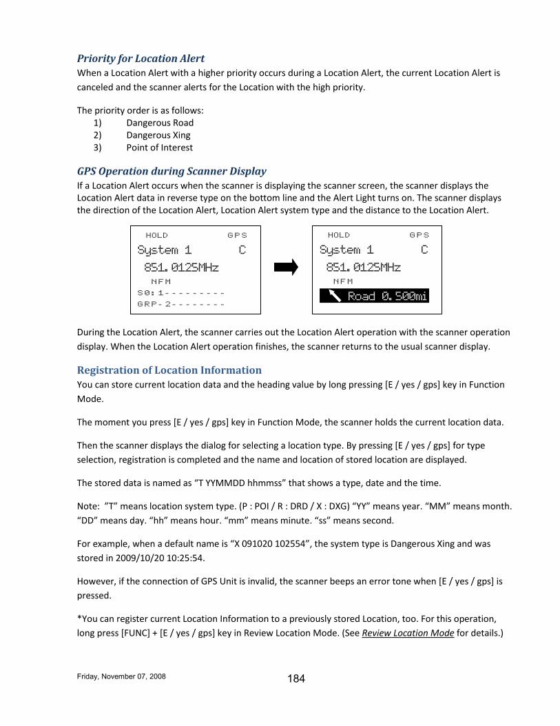
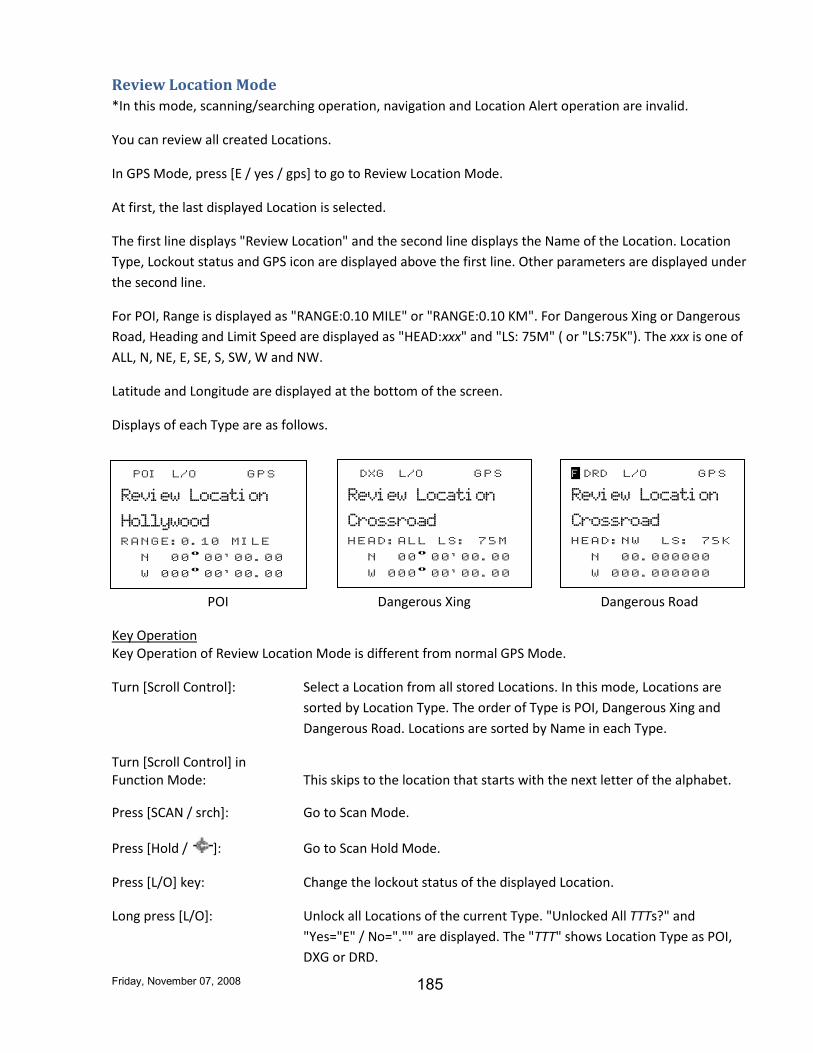
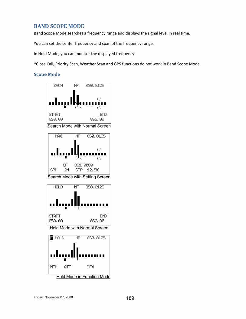
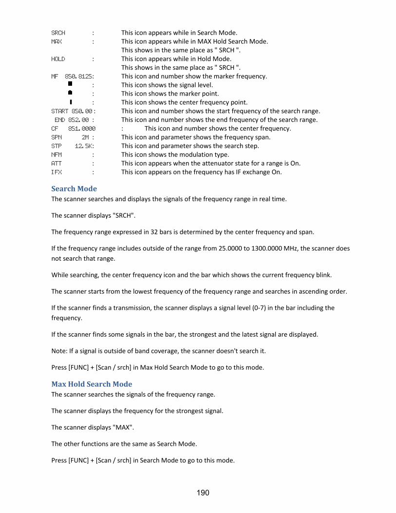

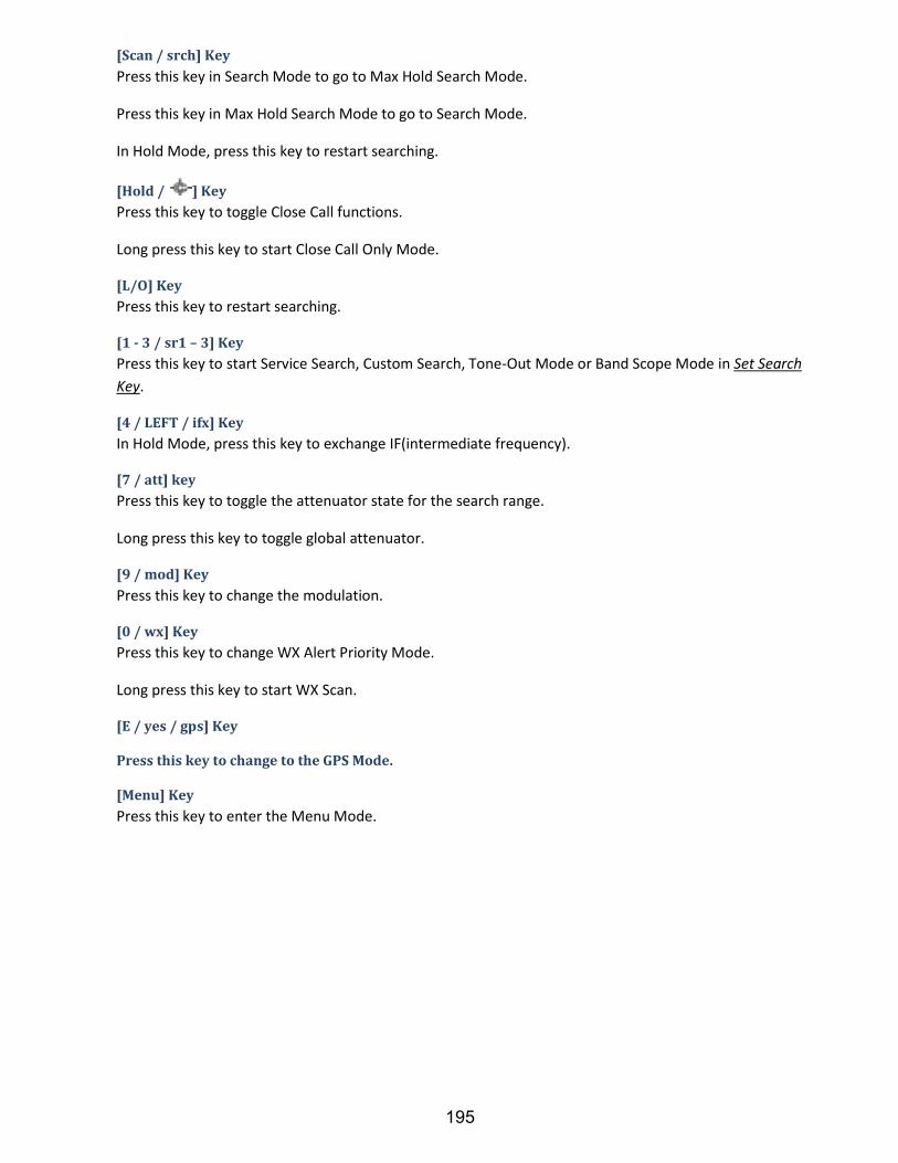
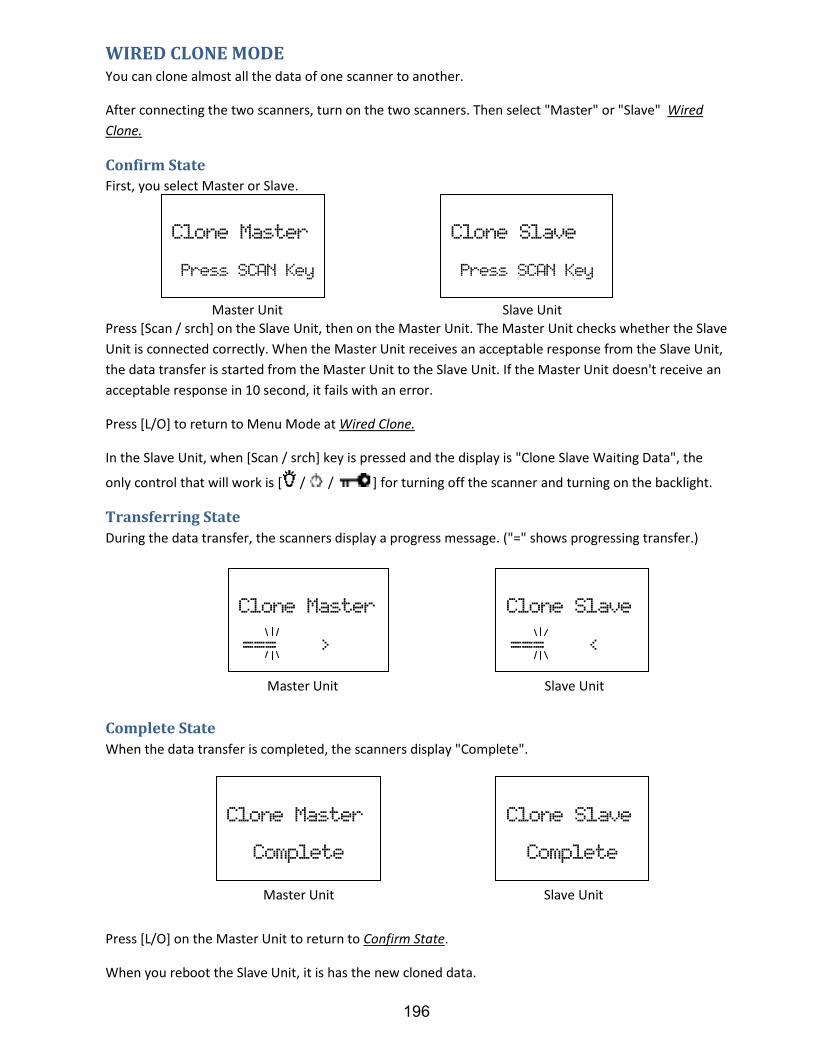

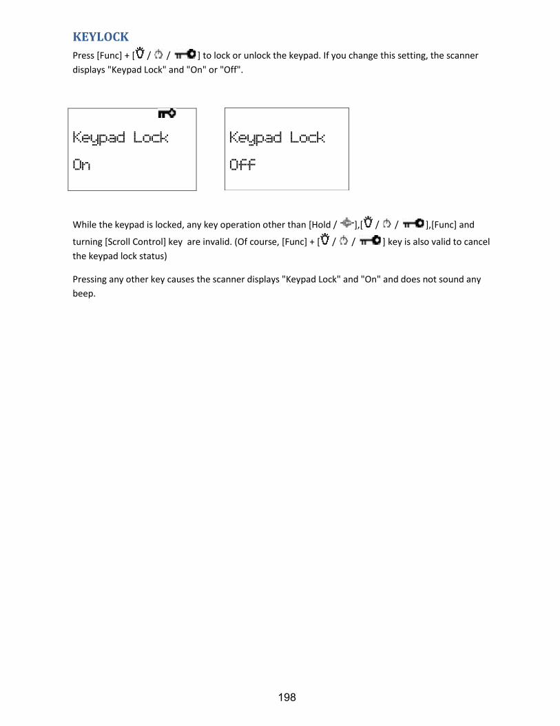
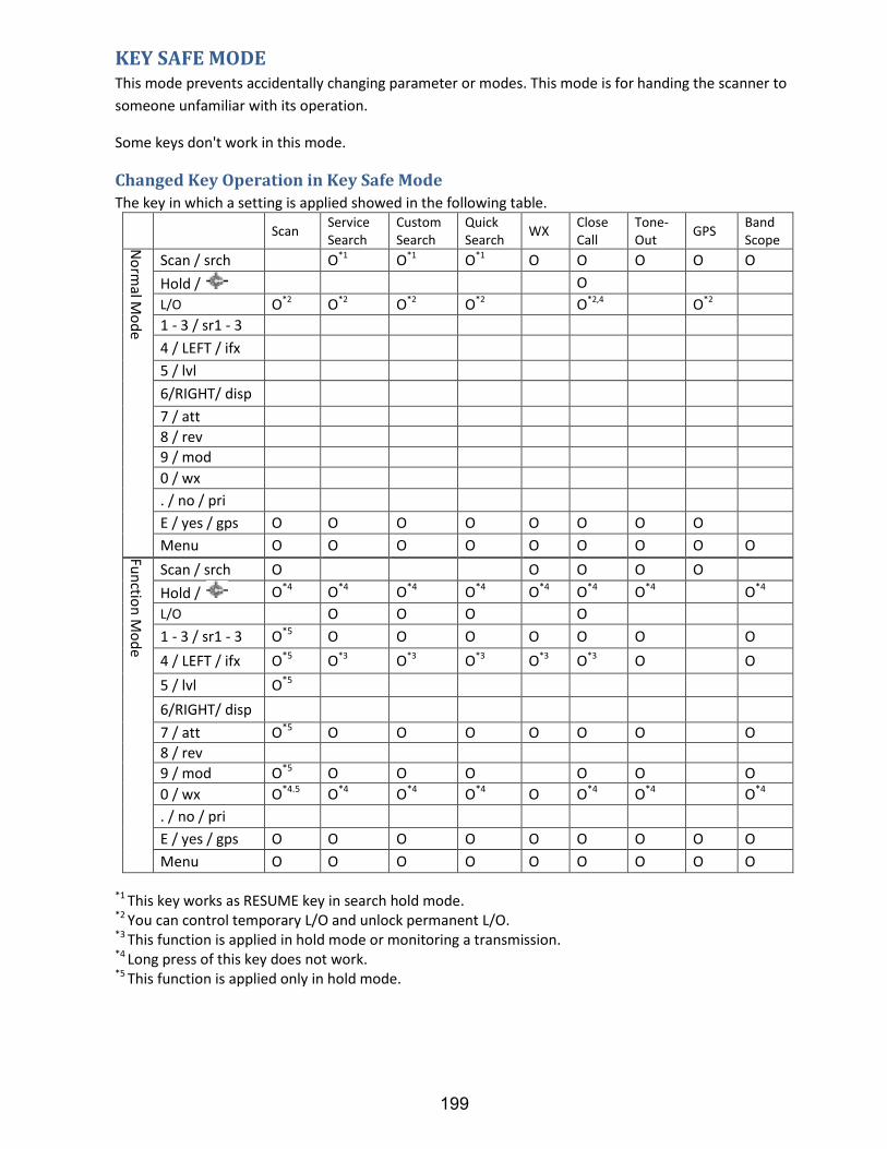

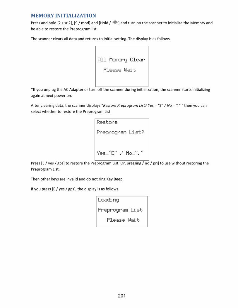
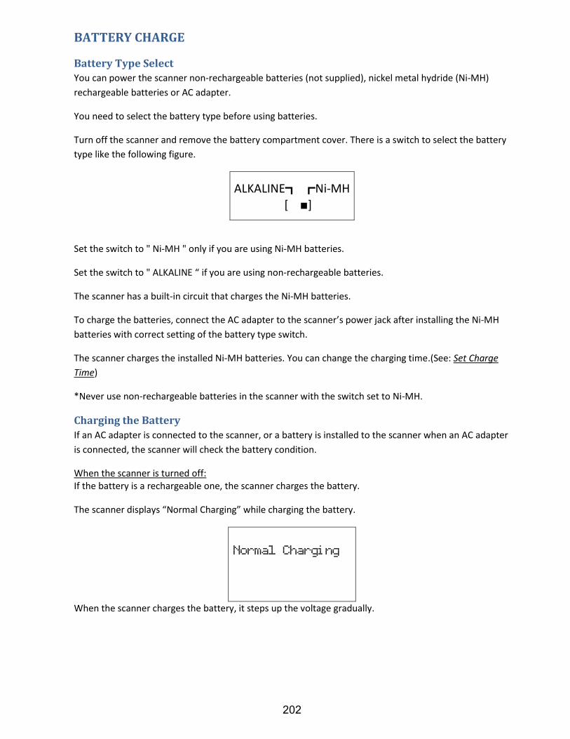
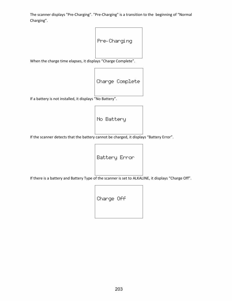
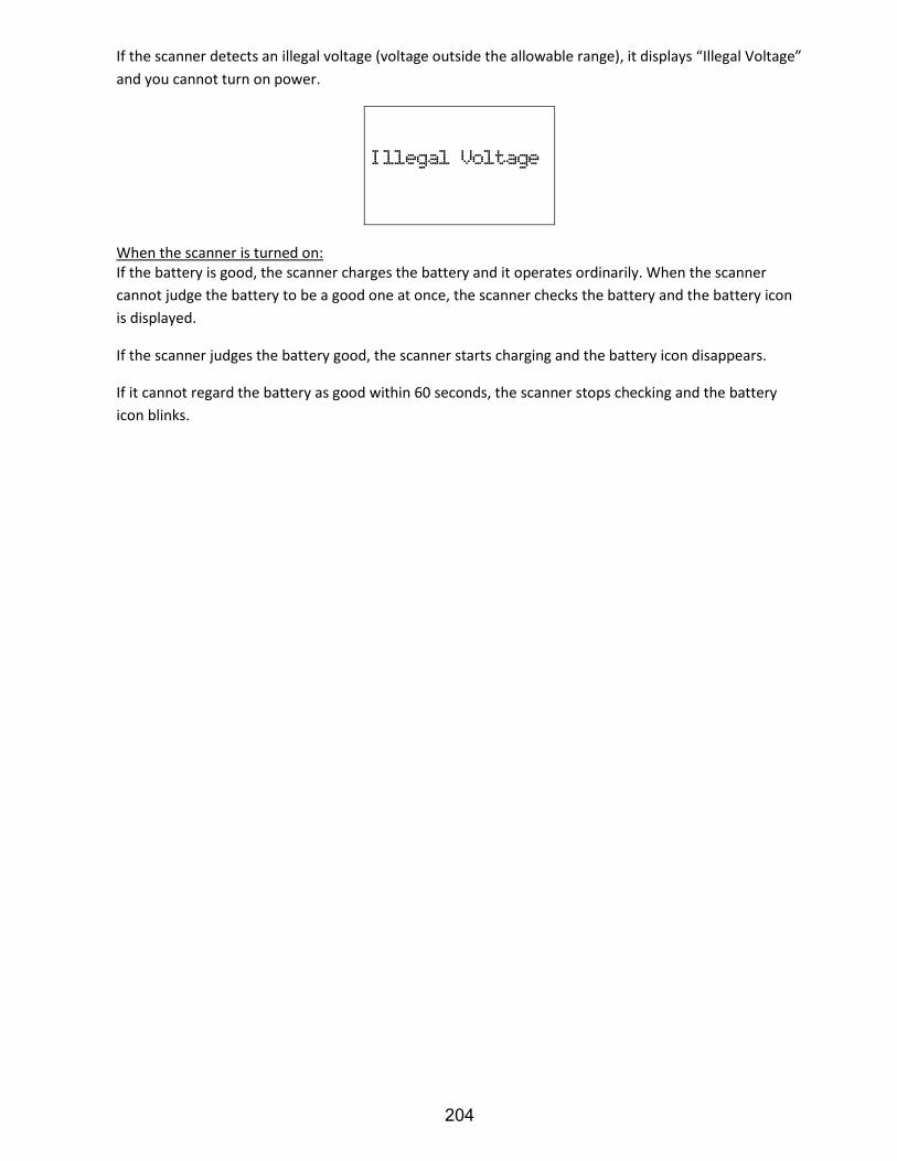
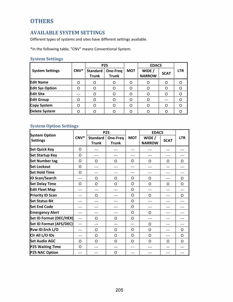
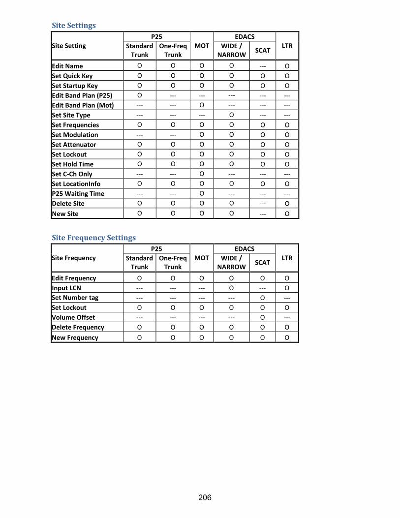
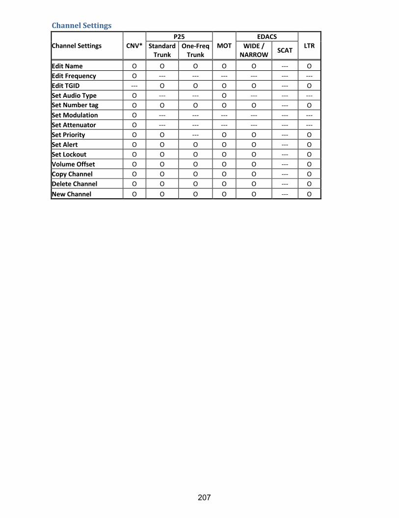


![[XLS] 7-10... · Web view1 0 0 0 2 0 0 0 3 0 0 0 4 0 0 0 5 0 0 0 6 0 0 0 7 0 0 0 8 0 0 0 9 0 0 0 10 0 0 0 11 0 0 0 12 0 0 0 13 0 0 0 14 0 0 0 15 0 0 0 16 0 0 0 17 0 0 0 18 0 0 0 19](https://static.documents.pub/doc/80x56/5ae8a6607f8b9a29049069b5/xls-7-10web-view1-0-0-0-2-0-0-0-3-0-0-0-4-0-0-0-5-0-0-0-6-0-0-0-7-0-0-0-8-0.jpg)


