BE1-87T UHA-4 9-94 BE1-87T TRANSFORMER DIFFERENTIAL RELAY FUNCTIONAL DESCRIPTION Pages 2-5 SPECIFICATIONS Pages 6-7 EXTERNAL CONNECTIONS Pages 8-9 ORDERING Pages 10-11 The BE1-87T Transformer Differential Relay is designed as primary protection for power transformers against internal faults. Available in either single- or three-phase configurations, this solid-state relay compares the currents entering and leaving the protected transformer. If any imbalance is detected that is not attributable to other (tested) factors, the relay provides a contact closure to isolate the power trans- former to limit damage. FEATURES • Single- and three-phase configurations. • Input isolation. • Three-phase configuration includes internal phase shift compensation with zero-sequence current blocking. • 2nd- and 5th-harmonic restraint. • Adjustable through-current restraint. • % I OP display. • Tap scaling covers the range of 2.0 to 8.9 amperes in 0.1-ampere increments in 5 Ampere CT models, and 0.4 to 1.78 amperes in 0.02- ampere increments in 1 Ampere CT models. • Low sensing burden. • Maintains proper operation when tested for interference in accordance with IECC C37.90-1989, Trial-Use Standard Withstand Capability of Relay systems toRadiated electromagnetic Interference from Transceivers. • UL listed (except for 250Vdc power supply). • 2-year limited warranty. INSTRUCTION MANUAL Request publication 9-1713-00-990 P. O. BOX 269 HIGHLAND, ILLINOIS 62249, U.S .A. PHONE 618-654-2341 FAX 618- 654-2351 ADDITIONAL INFORMATION
The BE1-87T Transformer Differential Relay is designed as primary protection forpower transformers against internal faults. Available in either single- or three-phaseconfigurations, this solid-state relay compares the currents entering and leaving theprotected transformer. If any imbalance is detected that is not attributable to other(tested) factors, the relay provides a contact closure to isolate the power trans-former to limit damage.
FEATURES• Single- and three-phase configurations.• Input isolation.• Three-phase configuration includes internal phase shift compensation
with zero-sequence current blocking.• 2nd- and 5th-harmonic restraint.• Adjustable through-current restraint.• % IOP display.• Tap scaling covers the range of 2.0 to 8.9 amperes in 0.1-ampere
increments in 5 Ampere CT models, and 0.4 to 1.78 amperes in 0.02-ampere increments in 1 Ampere CT models.
• Low sensing burden.• Maintains proper operation when tested for interference in accordance with IECC
C37.90-1989, Trial-Use Standard Withstand Capability of Relay systems to Radiated electromagnetic Interference from Transceivers.
The “calculate max individual current” circuit deter-mines which scaled input is receiving the greatest
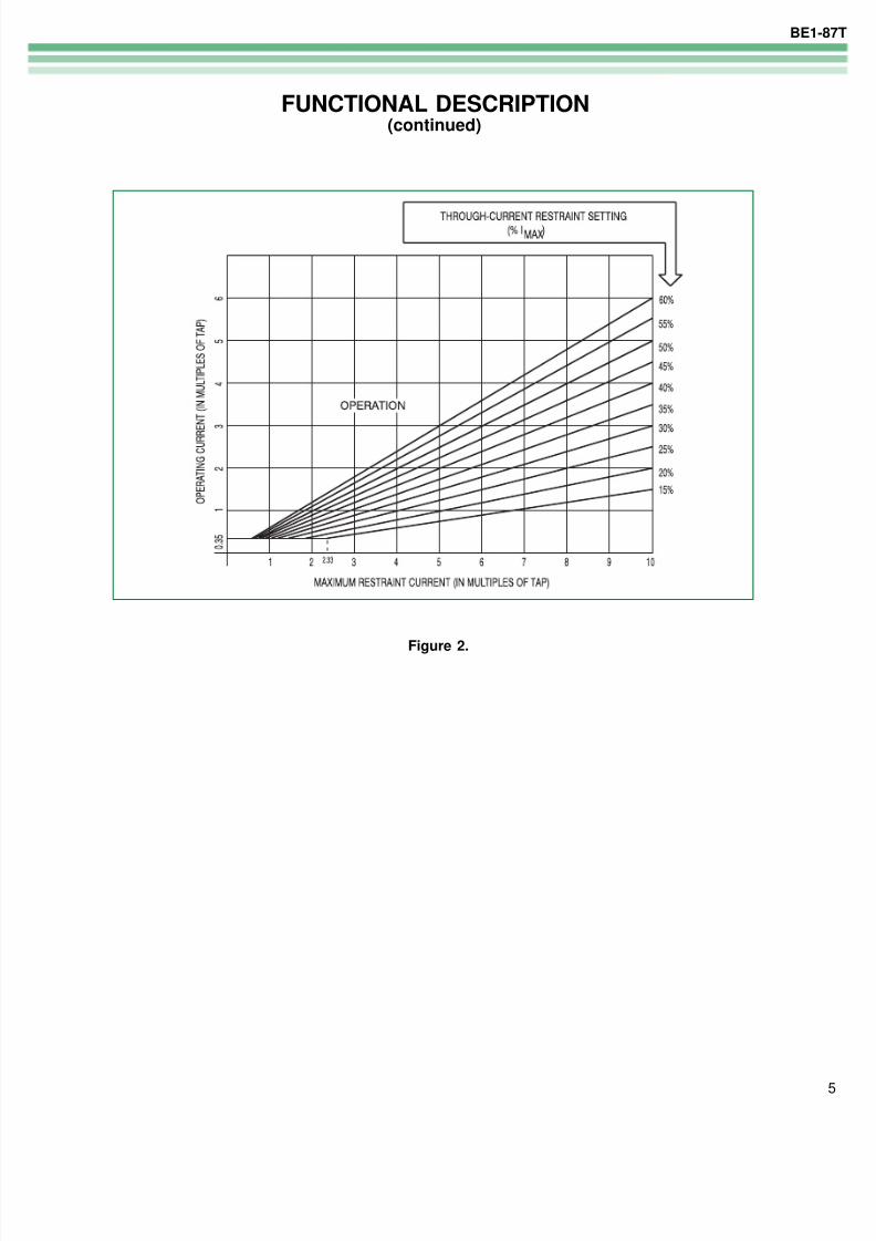
current. The resulting signal, %I MAX (figure 2) repre-sents the percentage of through-current and isextended to the trip comparator, where it is comparedto the operating current.
If the operating current is greater than %I MAX andthere is no inhibit signal present, a restrained trip isproduced; also an auxiliary output will occur (depend-ing on relay configuration).
Harmonic Restraints
The restrained trip output may be inhibited by eitherof two harmonic restraints. These are generated byfilters tuned to the second- and fifth-harmonic contentof the operate current. Comparators monitor thesesignals. When the fifth-harmonic content exceeds35% of the operate current (indicating overexcitationof the transformer), or when the 2nd-harmoniccontent exceeds 12% (single-phase) or 18% (three-phase) of the operating current (indicating a magneticinrush condition), an inhibit signal blocks operation ofthe Restrained output relay. The three-phase modeuses summing of the second harmonic signal toprovide secure operation.
Critical Speed Applications (Option)
On some applications, overall fault clearing time canbe a major issue. The 87T can optionally be config-ured with a faster overall operating speed for theseapplications.
GENERAL
The BE1-87T is a solid-state relay to protect power
transformers by providing an output contact closurewhen the “scaled” currrent into the protected trans-former does not equal the “scaled” current out (withindefined limits). The relay is harmonically restrained toprevent tripping during intial energization andoverexcitation conditions. A through-current restraintalso provides security against tripping for externalfaults. An unrestrained tripping element is included toprovide high speed tripping in the event of a severeinternal fault.
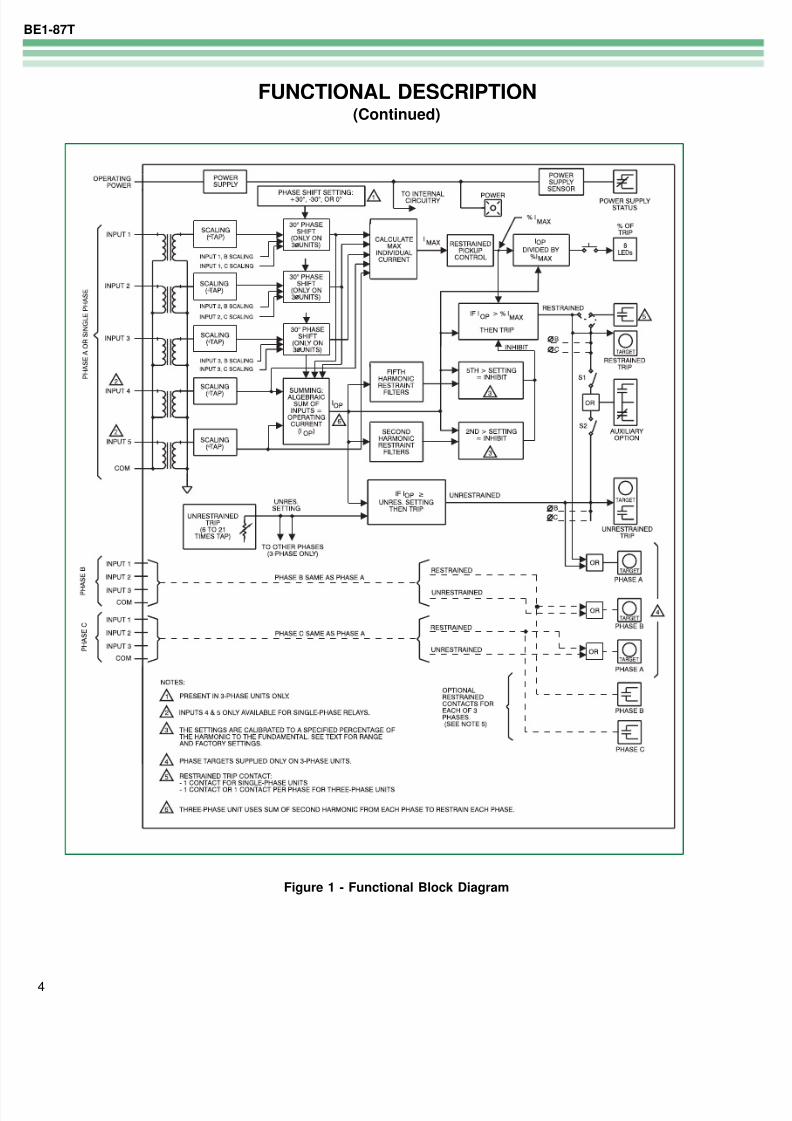
The functional block diagram in Figure 1 illustrates theoverall operation of the BE1-87T. Since the relay is
available as either a single-phase or three-phasedevice, only phase A is shown in detail. Phases B andC, when present, are functionally similar to phase A.
CURRENT TRANSFORMERS
A standard current transformer with a 5A or 1A sec-ondary winding supplies sensing current for each input.These current transformers may be shared with otherprotective relays due to the isolation of individualinputs. The sensed currents are, in turn, applied to theinternal input transformers of the relay.
SCALING
Input currents are scaled by rotary switches thatintroduce resitances to the internal CT secondaries.The switches are calibrated in 0.1 ampere incrementsfrom 2.0 to 8.9 amperes (5 ampere CT models) and0.02 ampere increments from 0.4 to 1.78 amperes(1 ampere CT models). The many graduations ofadjustment are provided to allow each input to ap-proach an ideal representation of its actual operatingper unit value.
SUMMING
The analog signals representing each input’s contribu-tion are electronically sound. This process producesthe operating current (I OP ), which is the algebraic sumof the input currents.
Ideally, with perfectly matched CTs, a transformerwithout an internal fault would have an I OP of zero. Afault would be indicated by a nonzero I OP . However,saturation caused by heavy through-currents, magneticinrush or overexcitation can cause I OP to be present
The 87T can be optionally configured with a front panel
indication of system unbalance, to permit verification ofproper relay connections. The display consists of 8LEDs, which show the unbalance as a percent of trip.
IOP
% IMAX( )UNRESTRAINED TRIP OUTPUT
The I OP signal is also compared against a referenceestablished by the front panel UNRESTRAINED TRIPsetting. When this reference is exceeded, the unre-strained trip output relay is energized. The unre-strained trip is not affected by through-current orharmonic content.
PHASE SHIFT AND ZERO SEQUENCE FILTER(Available only in three-phase relays)
In three-phase relays, the phase-shift jumpers may beplaced to provide +30 degrees, -30 degrees or nocompensation for delta-wye or wye-delta transformerconfigurations. The ±30 degree phase shift will accom-plish the corresponding zero sequence blocking.
In single-phase relays, the internal phase shift is notavailable and the phase shift compensation and zerosequence filtering must be provided by the external CTconnections.
AUXILIARY RELAY (Option)
The auxiliary relay is controlled by two switches, S1and S2, which allow it to respond to a restrained trip, orto an unrestrained trip, or both. The S1 and S2switches are located on the mother board.
POWER SUPPLY
The solid-state power supply is a low burden, flybackswitching design which delivers a nominal ±12 Vdc tointernal circuitry. The power supply inputs are notpolarity sensitive. A red LED illuminates to indicate thatthe power supply is functioning properly.
The Type Y power supply includes a field adjustablelink that is factory set for 125 Vdc input power. Analternative position is selected for 48-volt input power.
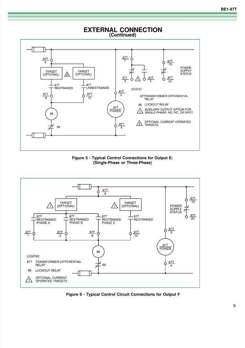
POWER SUPPLY STATUS OUTPUT
The power supply status output relay has a normally
closed (NC) contact. This relay is energized by thepresence of nominal voltage at the output of thepower supply. Normal operating voltage then keepsthe relay continuously energized and its contactopen. However, if the power supply voltage fallsbelow requirements, the power supply status outputrelay will de-energize, and close its contact.
TARGET INDICATOR CIRCUITS (Option)
When a target option is specified, magneticallylatched indicators are included within the relay. Theymay be actuated by either of two methods as definedby the style chart designation.
Internally operated (type C) targets are operated byinternal driver circuits that are actuated by a signalfrom the relay’s internal logic circuits, paralleling theclose signal to the output relay.
Current operated (type D) targets are actuated whena minimum of 0.2 A flows through the relay’s outputcontacts. To accomplish this, a special reed relay isplaced in series with the output contacts to enable thetarget indicator. (The series impedance of the reed
relay is less than 0.1 ohm.)
When targets are specified, the BE1-87T relay issupplied with FUNCTION (RESTRAINED and UNRE-STRAINED) targets. Three-phase styles are addition-ally supplied with ELEMENT (PHASE A, B, C)targets.
PUSH-TO-ENERGIZE OUTPUT SWITCHES(Option)
If Option 2-S has been selected, small pushbuttonswitches are included for the restrained and unre-
strained functions. Each switch will energize thecorresponding output relays for test purposes. Toprevent accidental operation of these switches, theyare recessed behind the front panel of the relay, andare accessed by inserting a thin non-conducting rodthrough access holes in the panel.
CURRENT SENSING INPUTSThe unit is designed to operate from the second-ary of current transformers rated at either 5A or1A. Frequency range is ±5 Hz of nominal. Maxi-mum current per input (5 Ampere CT Models)20A continuous; 250A or 50 X tap (whichever isless) for 1 second; (1 Ampere CT Models) 4Acontinuous; 50A or 10 X tap (whichever is less)for 1 second. For ratings other than one second,the rating may be calculated as:
I = ____ t
where t is the time (in seconds) that the currentflows, and K = 250A or 50 times tap, whichever isless (5A CT Models); or K = 50A or 10 times tap,
whichever is less (1A CT Models).
CURRENT SENSING BURDENLess than 0.1 ohm per phase.
SCALING CONTROL (or Tap Setting)Front panel rotary switches permit scaling thesensed input current (or Tap Setting) over therange of:(5 Ampere CT Models) 2.0 to 8.9A, in 0.1A
increments(1 Ampere CT Models) 0.4 to 1.78A, in 0.02Aincrements
RESTRAINED OUTPUT PICKUP CONTROLFront panel thumbwheel switches permit adjust-ment of the restrained pickup as a percentage ofthrough current, and over the range of 15 to 60%in increments of 5%. (Figure 2)
MINIMUM PICKUPIOP = 0.35 x tap setting ±6%. (Figure 2)
SECOND-HARMONIC RESTRAINTInhibit of the restrained output occurs when thesecond-harmonic component exceeds the pickupsetting which is internally adjustable over therange of 8% to 15% of the operating current forsingle-phase units, or 11% to 27% three-phaseunits. The factory setting is 12% for single-phaseunits and 18% for three-phase units.
FIFTH-HARMONIC RESTRAINTInhibit of the restrained output occurs when thefifth-harmonic component exceeds a pick-upsetting which has an internally adjustable rangeof 25% to 45% of the operating current. Thefactory setting is 35%.
UNRESTRAINED OUTPUT PICKUP CONTROLFront panel thumbwheel switches provide adjust-ment of the desired pickup point for the unre-strained element of the relay from 6 to 21 timesthe tap setting in increments of 1x tap.
OUTPUTSOutput Contacts are rated as follows.
Resistive120/240 Vac: Make 30A for 0.2 seconds, carry7A continuously, break 7A.250 Vac: Make and carry 30A for 0.2 seconds,carry 7A continuously, break 0.3A.500 Vdc: Make and carry 15A for 0.2 seconds,carry 7A continuously, break 0.1A.
TARGET INDICATORSInternally operated and current operated targetsare available (in accordance with the style num-ber).
Internally operated targets utilize the internal tripsignal to energize the output relay and the targetdrivers. Current operated targets are energized
by a minimum of 0.2A flowing through the outputcontacts.
The series impendence of the current operatedtarget is 0.1 ohms or less. The current operatedtargets are rated at 30A for 0.2 seconds, 7A for 2minutes and 3A continuous. Note: This is lessthan the rating of the output contact and canconstrain the control circuit.
Single-phase Units - When specified, either aninternally operated or a current operated targetwill be supplied for the relay.
Three-phase Units - When targets are specified,either internally operated or current operatedtargets indicate the function (Restrained orUnrestrained) that caused the trip as well as theassociated phase element (A,B,C).
ISOLATION1500 Vac at 60 Hz for one minute in accordancewith IEC 255-5 and ANSI/IEEE C37.90-1989(Dielectric Test).
SURGE WITHSTAND CAPABILITYQualified to: ANSI/IEEE C37.90-1989, Standard Surge Withstand Capability Test and Fast Tran- sient Test , and IEC 255-5 Impulse Test and Dielectric Test.
RADIO FREQUENCY INTERFERENCE (RFI)Maintains proper operation when tested forinterference in accordance with IECC C37.90-1989, Trial-Use Standard Withstand Capability of Relay systems to Radiated electromagnetic Interference from Transceivers .
SHOCKIn standard tests, the relay has withstood 15 g ineach of three mutually perpendicular axes withoutstructural damage or degradation of performance.
VIBRATIONIn standard tests, the relay has withstood 2 g ineach of three mutually perpendicular axes sweptover the range of 10 to 500 Hz for a total of sixsweeps, 15 minutes each sweep, without struc-tural damage or degradation of performance.
OPERATING TEMPERATURE-40°C to +70°C (-40°F to +158°F)
STORAGE TEMPERATURE-65°C to +100°C (-85°F to +212°F)
TypeNominal
InputVoltage
Input VoltageRange
Burden atNominal
(Energized)
Burden atNominal
(De-Energized)
J 125 Vdc120 Vac
62 - 150 Vdc90 - 132 Vac
9.0 W21.0 VA
6.5 W16.0 VA
K 48 Vdc 24 - 60 Vdc 8.5 W 6.0 W
L 24 Vdc 12 - 32 Vdc 9.0 W 6.5 W
Y 48 Vdc125 Vdc
24 - 60 Vdc62 - 150 Vdc
7.5 W8.5 W
6.0 W6.5 W
Z 250 Vdc
230 Vdc
140 - 280 Vdc
190 - 270 Vac
9.5 W
28.0 VA
7.7 W
26.6 VA
WEIGHT22.3 pounds (three-phase unit)
19.5 pounds (single-phase unit)
CASE SIZEM1 case (double ended).Refer to Bulletin SDA for dimensions.
AGENCY RATINGS UL listed (except for 250Vdc power supply).