Page 1
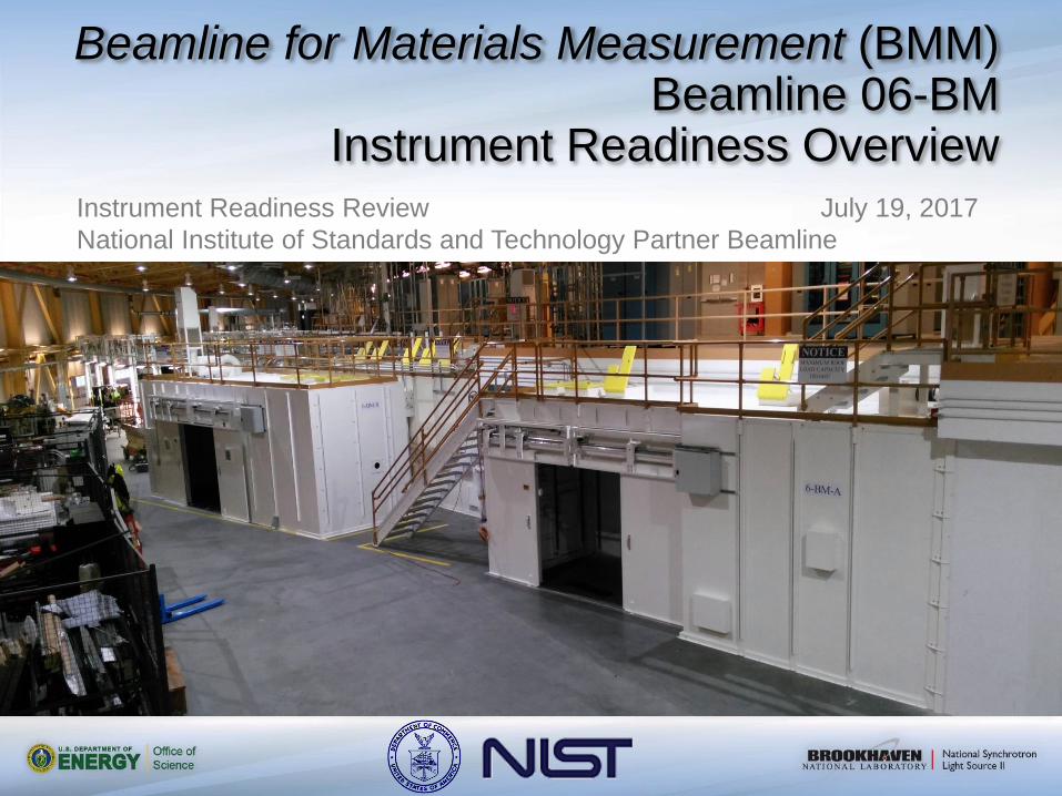
Beamline for Materials Measurement (BMM) Beamline 06-BM
Instrument Readiness Overview
Instrument Readiness Review July 19, 2017
National Institute of Standards and Technology Partner Beamline
Page 2
Background Pillar1: Documentation Pillar II: Hardware Pillar III: Personnel
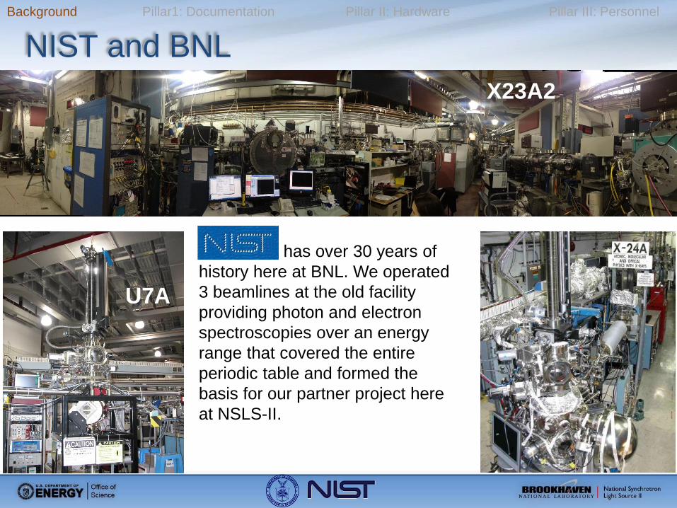
NIST and BNL
has over 30 years of
history here at BNL. We operated
3 beamlines at the old facility
providing photon and electron
spectroscopies over an energy
range that covered the entire
periodic table and formed the
basis for our partner project here
at NSLS-II.
X23A2
U7A
Page 3
Background Pillar1: Documentation Pillar II: Hardware Pillar III: Personnel
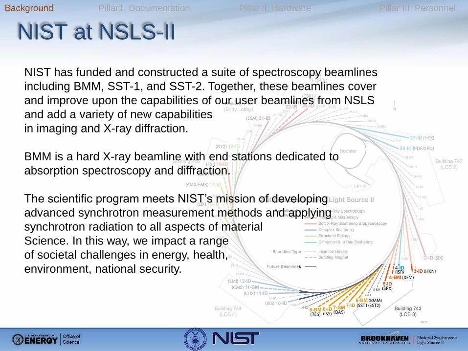
NIST at NSLS-II
NIST has funded and constructed a suite of spectroscopy beamlines
including BMM, SST-1, and SST-2. Together, these beamlines cover
and improve upon the capabilities of our user beamlines from NSLS
and add a variety of new capabilities
in imaging and X-ray diffraction.
BMM is a hard X-ray beamline with end stations dedicated to
absorption spectroscopy and diffraction.
The scientific program meets NIST’s mission of developing
advanced synchrotron measurement methods and applying
synchrotron radiation to all aspects of material
Science. In this way, we impact a range
of societal challenges in energy, health,
environment, national security.
Page 4
Background Pillar1: Documentation Pillar II: Hardware Pillar III: Personnel
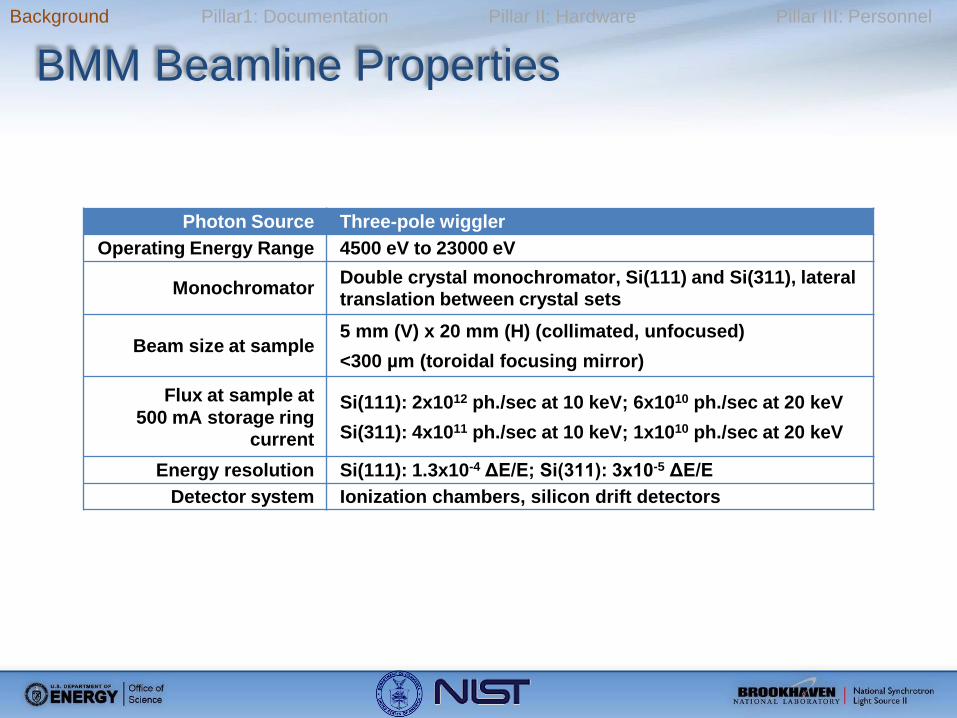
BMM Beamline Properties
Photon Source Three-pole wiggler
Operating Energy Range 4500 eV to 23000 eV
Monochromator Double crystal monochromator, Si(111) and Si(311), lateral translation between crystal sets
Beam size at sample 5 mm (V) x 20 mm (H) (collimated, unfocused)
<300 µm (toroidal focusing mirror)
Flux at sample at
500 mA storage ring current
Si(111): 2x10¹² ph./sec at 10 keV; 6x10¹⁰ ph./sec at 20 keV
Si(311): 4x10¹¹ ph./sec at 10 keV; 1x10¹⁰ ph./sec at 20 keV
Energy resolution Si(111): 1.3x10⁻⁴ ΔE/E; Si(311): 3x10⁻⁵ ΔE/E
Detector system Ionization chambers, silicon drift detectors
Page 5
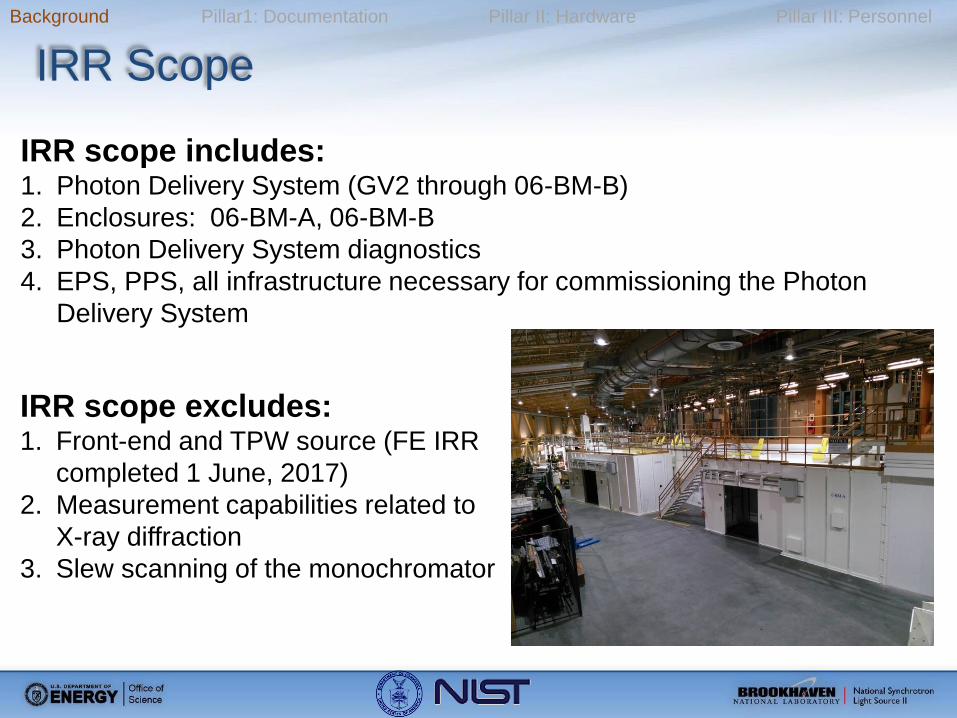
IRR scope includes: 1. Photon Delivery System (GV2 through 06-BM-B)
2. Enclosures: 06-BM-A, 06-BM-B
3. Photon Delivery System diagnostics
4. EPS, PPS, all infrastructure necessary for commissioning the Photon
Delivery System
IRR scope excludes: 1. Front-end and TPW source (FE IRR
completed 1 June, 2017)
2. Measurement capabilities related to
X-ray diffraction
3. Slew scanning of the monochromator
Background Pillar1: Documentation Pillar II: Hardware Pillar III: Personnel
IRR Scope
Page 6
Background Pillar1: Documentation Pillar II: Hardware Pillar III: Personnel
Self-Identified Pre-Start Findings
None as of 11 July, 2017
Page 7
Background Pillar1: Documentation Pillar II: Hardware Pillar III: Personnel
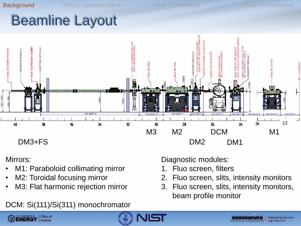
Beamline Layout
1 12
M1
DM1
DCM
DM2
M2 M3
DM3+FS
Mirrors:
• M1: Paraboloid collimating mirror
• M2: Toroidal focusing mirror
• M3: Flat harmonic rejection mirror
DCM: Si(111)/Si(311) monochromator
Diagnostic modules:
1. Fluo screen, filters
2. Fluo screen, slits, intensity monitors
3. Fluo screen, slits, intensity monitors,
beam profile monitor
Page 8
Background Pillar1: Documentation Pillar II: Hardware Pillar III: Personnel
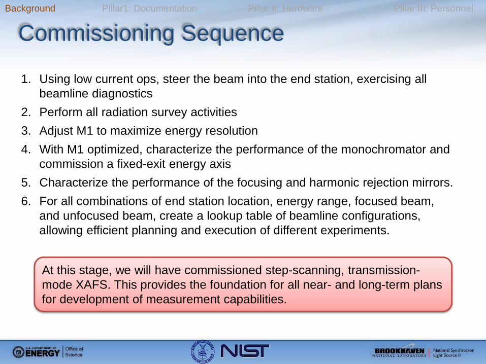
Commissioning Sequence
1. Using low current ops, steer the beam into the end station, exercising all
beamline diagnostics
2. Perform all radiation survey activities
3. Adjust M1 to maximize energy resolution
4. With M1 optimized, characterize the performance of the monochromator and
commission a fixed-exit energy axis
5. Characterize the performance of the focusing and harmonic rejection mirrors.
6. For all combinations of end station location, energy range, focused beam,
and unfocused beam, create a lookup table of beamline configurations,
allowing efficient planning and execution of different experiments.
At this stage, we will have commissioned step-scanning, transmission-
mode XAFS. This provides the foundation for all near- and long-term plans
for development of measurement capabilities.
Page 9
Background Pillar1: Documentation Pillar II: Hardware Pillar III: Personnel
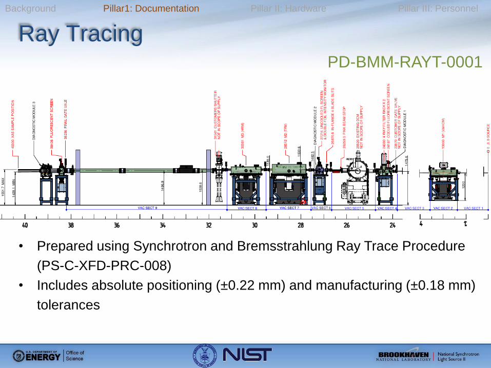
Ray Tracing
• Prepared using Synchrotron and Bremsstrahlung Ray Trace Procedure
(PS-C-XFD-PRC-008)
• Includes absolute positioning (±0.22 mm) and manufacturing (±0.18 mm)
tolerances
PD-BMM-RAYT-0001
Page 10
Background Pillar1: Documentation Pillar II: Hardware Pillar III: Personnel
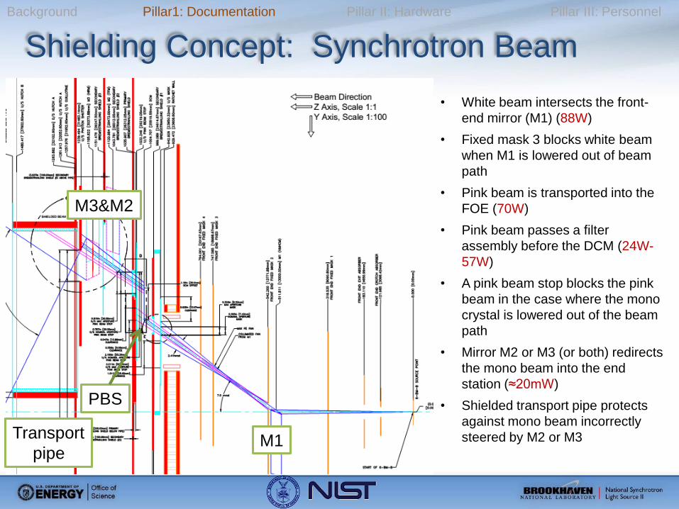
Shielding Concept: Synchrotron Beam
• White beam intersects the front-
end mirror (M1) (88W)
• Fixed mask 3 blocks white beam
when M1 is lowered out of beam
path
• Pink beam is transported into the
FOE (70W)
• Pink beam passes a filter
assembly before the DCM (24W-
57W)
• A pink beam stop blocks the pink
beam in the case where the mono
crystal is lowered out of the beam
path
• Mirror M2 or M3 (or both) redirects
the mono beam into the end
station (≈20mW)
• Shielded transport pipe protects
against mono beam incorrectly
steered by M2 or M3 M1
M3&M2
PBS
Transport
pipe
Page 11
Background Pillar1: Documentation Pillar II: Hardware Pillar III: Personnel
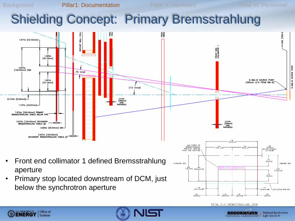
Shielding Concept: Primary Bremsstrahlung
• Front end collimator 1 defined Bremsstrahlung
aperture
• Primary stop located downstream of DCM, just
below the synchrotron aperture
Page 12
Background Pillar1: Documentation Pillar II: Hardware Pillar III: Personnel
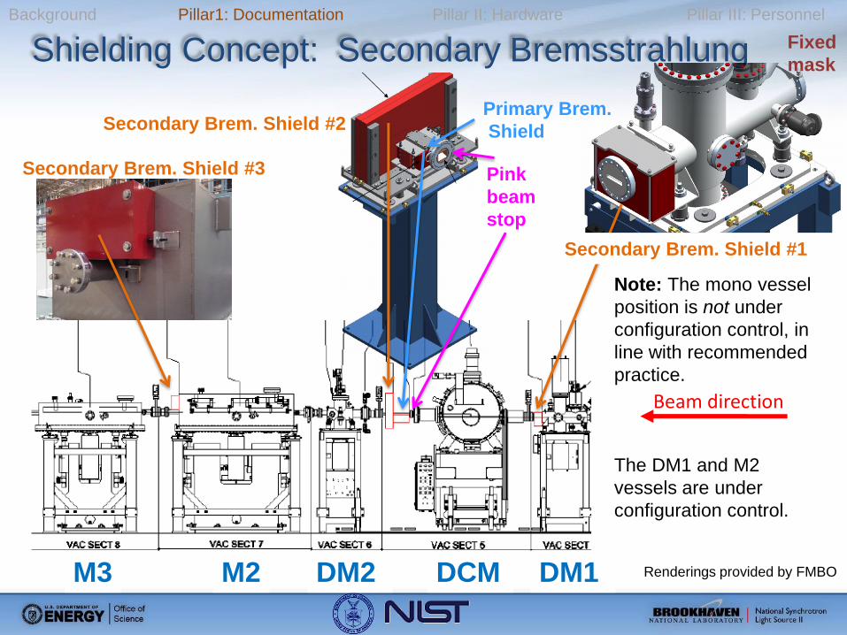
Shielding Concept: Secondary Bremsstrahlung
M2 M3 DCM DM2 DM1
Note: The mono vessel
position is not under
configuration control, in
line with recommended
practice.
The DM1 and M2
vessels are under
configuration control.
Beam direction
Secondary Brem. Shield #3
Secondary Brem. Shield #1
Secondary Brem. Shield #2 Primary Brem.
Shield
Pink
beam
stop
Renderings provided by FMBO
Fixed
mask
Page 13
Background Pillar1: Documentation Pillar II: Hardware Pillar III: Personnel
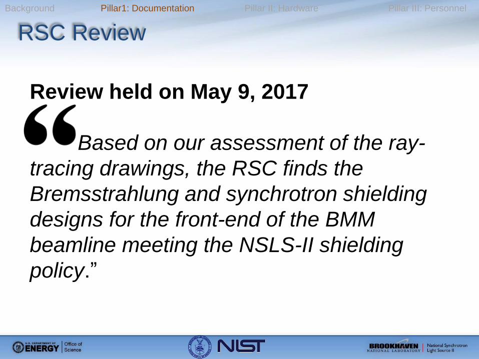
RSC Review
Review held on May 9, 2017
Based on our assessment of the ray-
tracing drawings, the RSC finds the
Bremsstrahlung and synchrotron shielding
designs for the front-end of the BMM
beamline meeting the NSLS-II shielding
policy.”
Page 14
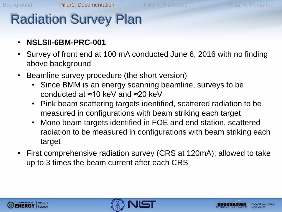
Background Pillar1: Documentation Pillar II: Hardware Pillar III: Personnel
Radiation Survey Plan
• NSLSII-6BM-PRC-001
• Survey of front end at 100 mA conducted June 6, 2016 with no finding
above background
• Beamline survey procedure (the short version)
• Since BMM is an energy scanning beamline, surveys to be
conducted at ≈10 keV and ≈20 keV
• Pink beam scattering targets identified, scattered radiation to be
measured in configurations with beam striking each target
• Mono beam targets identified in FOE and end station, scattered
radiation to be measured in configurations with beam striking each
target
• First comprehensive radiation survey (CRS at 120mA); allowed to take
up to 3 times the beam current after each CRS
Page 15
Background Pillar1: Documentation Pillar II: Hardware Pillar III: Personnel
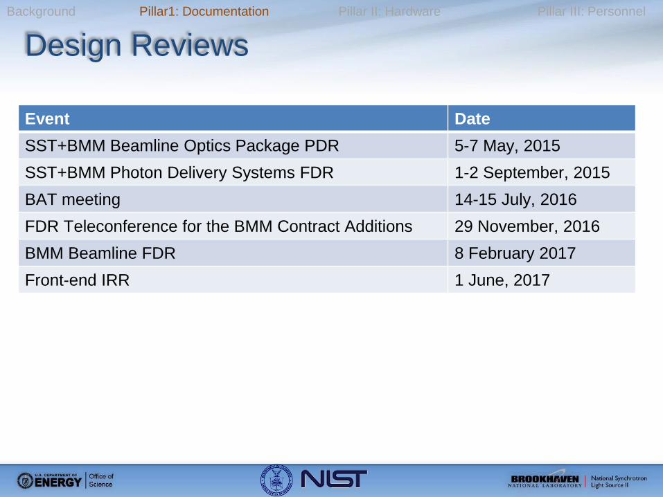
Design Reviews
Event Date
SST+BMM Beamline Optics Package PDR 5-7 May, 2015
SST+BMM Photon Delivery Systems FDR 1-2 September, 2015
BAT meeting 14-15 July, 2016
FDR Teleconference for the BMM Contract Additions 29 November, 2016
BMM Beamline FDR 8 February 2017
Front-end IRR 1 June, 2017
Page 16
Background Pillar1: Documentation Pillar II: Hardware Pillar III: Personnel
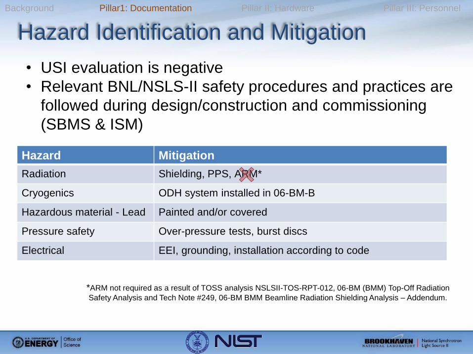
Hazard Identification and Mitigation
• USI evaluation is negative
• Relevant BNL/NSLS-II safety procedures and practices are
followed during design/construction and commissioning
(SBMS & ISM)
Hazard Mitigation
Radiation Shielding, PPS, ARM*
Cryogenics ODH system installed in 06-BM-B
Hazardous material - Lead Painted and/or covered
Pressure safety Over-pressure tests, burst discs
Electrical EEI, grounding, installation according to code
*ARM not required as a result of TOSS analysis NSLSII-TOS-RPT-012, 06-BM (BMM) Top-Off Radiation
Safety Analysis and Tech Note #249, 06-BM BMM Beamline Radiation Shielding Analysis – Addendum.
Page 17
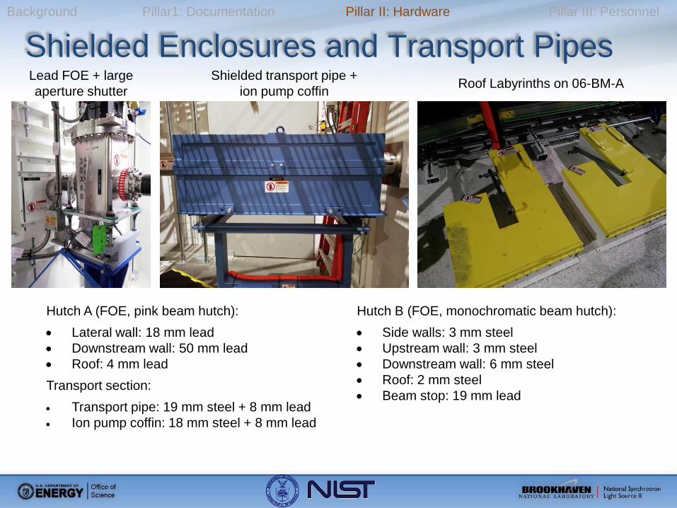
Background Pillar1: Documentation Pillar II: Hardware Pillar III: Personnel
Shielded Enclosures and Transport Pipes Lead FOE + large
aperture shutter
Shielded transport pipe +
ion pump coffin Roof Labyrinths on 06-BM-A
Hutch A (FOE, pink beam hutch):
Lateral wall: 18 mm lead
Downstream wall: 50 mm lead
Roof: 4 mm lead
Transport section:
Transport pipe: 19 mm steel + 8 mm lead
Ion pump coffin: 18 mm steel + 8 mm lead
Hutch B (FOE, monochromatic beam hutch):
Side walls: 3 mm steel
Upstream wall: 3 mm steel
Downstream wall: 6 mm steel
Roof: 2 mm steel
Beam stop: 19 mm lead
Page 18
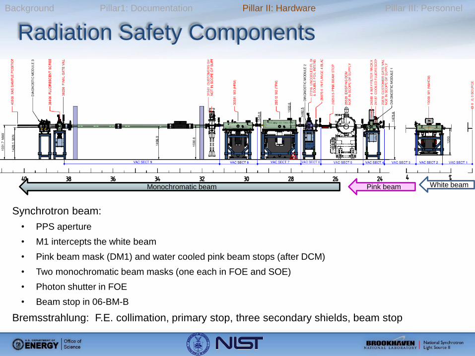
Background Pillar1: Documentation Pillar II: Hardware Pillar III: Personnel
Radiation Safety Components
Monochromatic beam Pink beam White beam
Synchrotron beam:
• PPS aperture
• M1 intercepts the white beam
• Pink beam mask (DM1) and water cooled pink beam stops (after DCM)
• Two monochromatic beam masks (one each in FOE and SOE)
• Photon shutter in FOE
• Beam stop in 06-BM-B
Bremsstrahlung: F.E. collimation, primary stop, three secondary shields, beam stop
Page 19
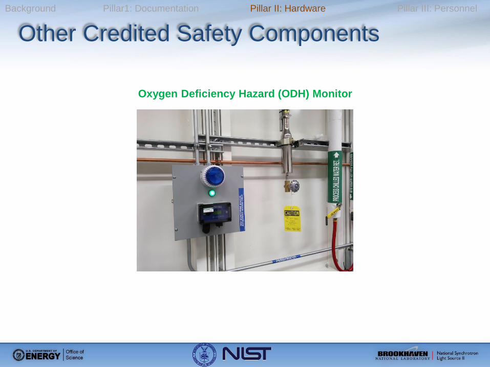
Background Pillar1: Documentation Pillar II: Hardware Pillar III: Personnel
Other Credited Safety Components
Oxygen Deficiency Hazard (ODH) Monitor
Page 20
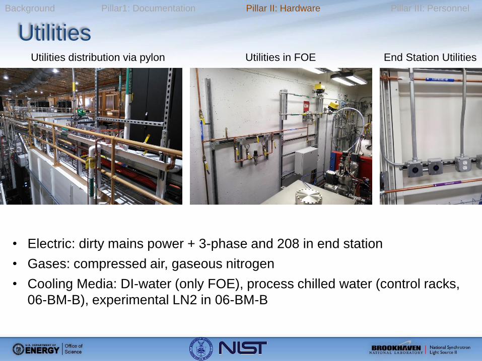
Background Pillar1: Documentation Pillar II: Hardware Pillar III: Personnel
Utilities Utilities distribution via pylon Utilities in FOE End Station Utilities
• Electric: dirty mains power + 3-phase and 208 in end station
• Gases: compressed air, gaseous nitrogen
• Cooling Media: DI-water (only FOE), process chilled water (control racks,
06-BM-B), experimental LN2 in 06-BM-B
Page 21
Background Pillar1: Documentation Pillar II: Hardware Pillar III: Personnel
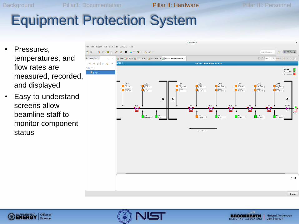
Equipment Protection System
• Pressures,
temperatures, and
flow rates are
measured, recorded,
and displayed
• Easy-to-understand
screens allow
beamline staff to
monitor component
status
Page 22
Background Pillar1: Documentation Pillar II: Hardware Pillar III: Personnel
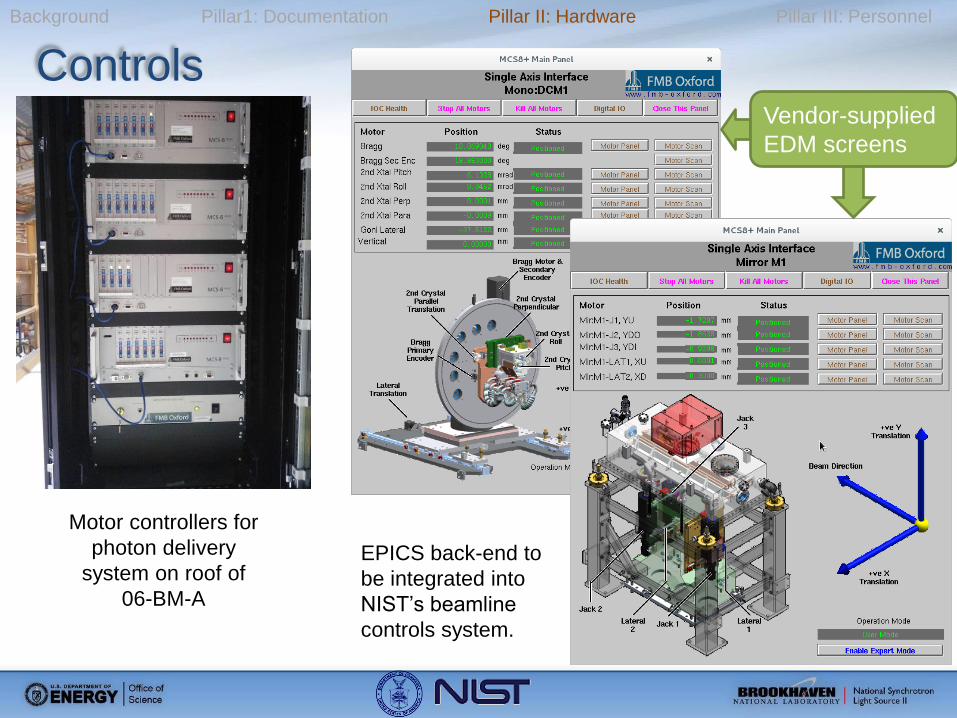
Controls
Motor controllers for
photon delivery
system on roof of
06-BM-A
EPICS back-end to
be integrated into
NIST’s beamline
controls system.
Vendor-supplied
EDM screens
Page 23
Background Pillar1: Documentation Pillar II: Hardware Pillar III: Personnel
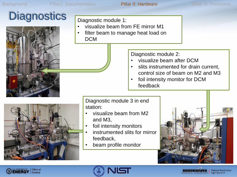
Diagnostics
Diagnostic module 3 in end
station:
• visualize beam from M2
and M3,
• foil intensity monitors
• instrumented slits for mirror
feedback,
• beam profile monitor
Diagnostic module 1:
• visualize beam from FE mirror M1
• filter beam to manage heat load on
DCM
Diagnostic module 2:
• visualize beam after DCM
• slits instrumented for drain current,
control size of beam on M2 and M3
• foil intensity monitor for DCM
feedback
Page 24
Background Pillar1: Documentation Pillar II: Hardware Pillar III: Personnel
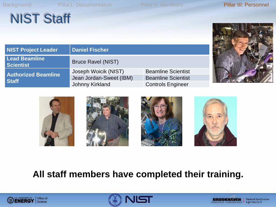
NIST Staff
NIST Project Leader Daniel Fischer
Lead Beamline
Scientist Bruce Ravel (NIST)
Authorized Beamline
Staff
Joseph Woicik (NIST) Beamline Scientist
Jean Jordan-Sweet (IBM) Beamline Scientist
Johnny Kirkland Controls Engineer
All staff members have completed their training.
Page 25
Background Pillar1: Documentation Pillar II: Hardware Pillar III: Personnel
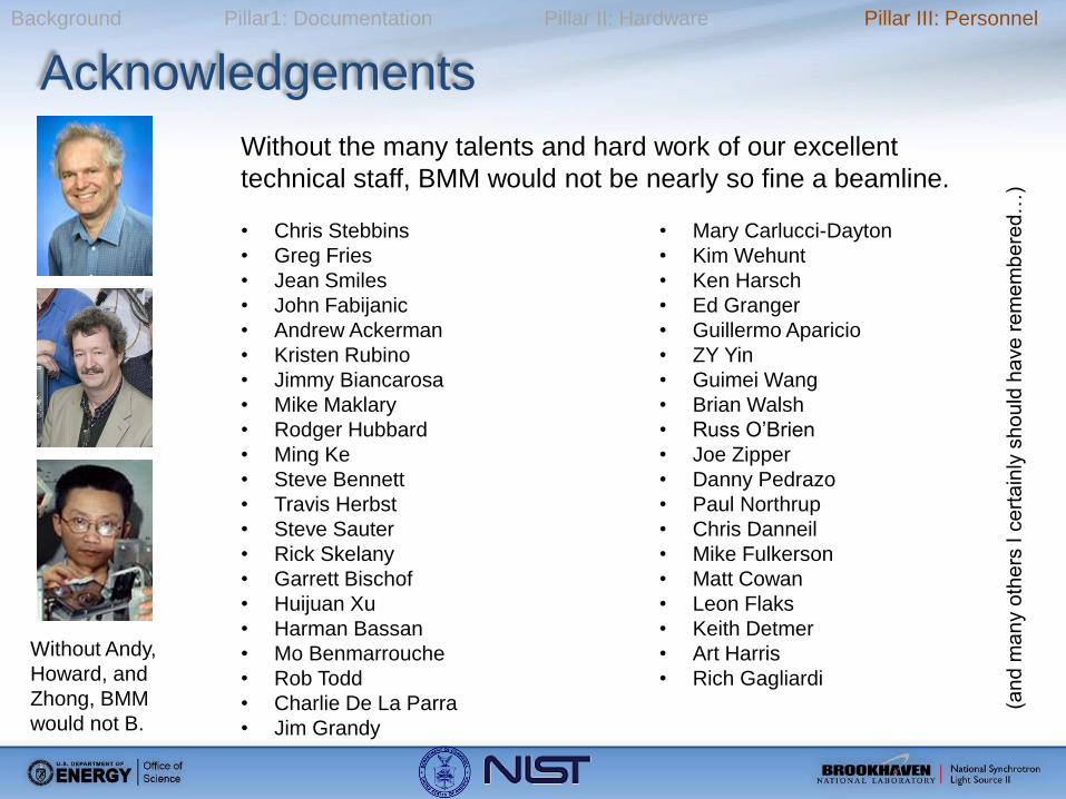
Acknowledgements
• Chris Stebbins
• Greg Fries
• Jean Smiles
• John Fabijanic
• Andrew Ackerman
• Kristen Rubino
• Jimmy Biancarosa
• Mike Maklary
• Rodger Hubbard
• Ming Ke
• Steve Bennett
• Travis Herbst
• Steve Sauter
• Rick Skelany
• Garrett Bischof
• Huijuan Xu
• Harman Bassan
• Mo Benmarrouche
• Rob Todd
• Charlie De La Parra
• Jim Grandy
• Mary Carlucci-Dayton
• Kim Wehunt
• Ken Harsch
• Ed Granger
• Guillermo Aparicio
• ZY Yin
• Guimei Wang
• Brian Walsh
• Russ O’Brien
• Joe Zipper
• Danny Pedrazo
• Paul Northrup
• Chris Danneil
• Mike Fulkerson
• Matt Cowan
• Leon Flaks
• Keith Detmer
• Art Harris
• Rich Gagliardi
Without Andy,
Howard, and
Zhong, BMM
would not B.
Without the many talents and hard work of our excellent
technical staff, BMM would not be nearly so fine a beamline.
(an
d m
an
y o
the
rs I c
ert
ain
ly s
ho
uld
ha
ve
re
me
mb
ere
d…
)
Page 26
• The Photon Delivery System is the scope of this IRR
• Initial Commissioning: • Configuration of all modes of the Photon Delivery System
• Establishment of step-scanning, transmission XAS on the XAS
end-station
• Future Commissioning: • Goniometer end-station
• Continuous scanning of the monochromator
• Beamline is ready for first light
• Endstation installation is complete for XAS end-station
Summary