37
Beams Division Seminar Configuration Management in the Tevatron – Alignment Ray Stefanski March 6, 2003
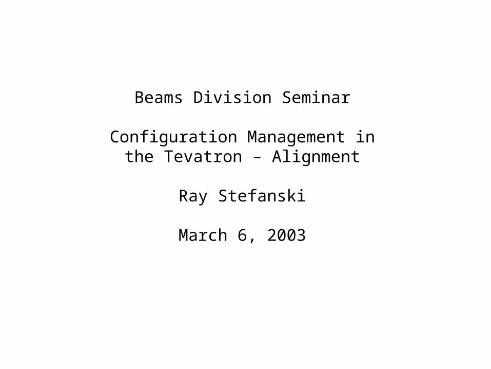
Beams Division Seminar
Configuration Management inthe Tevatron – Alignment
Ray Stefanski
March 6, 2003

CM focuses on controlling outcomes.
CM controls change, making sure that its impact is assessed and that every effort is made to prevent erosion of functionality or safety.
Configuration Management
Applies to any complex system, but we willconcentrate today on Tevatron magnet alignment and stability.

Organization
I would like to discuss alignment roughly alongchronological lines, beginning last Summer when Ifirst got involved. Our baseline dates to 1995.We will cover:
1. Data base development.2. Elevations.3. Roll measurements.4. Continuous elevation monitors.5. Smart Bolt measurements.6. Summary

Contributors:
Bruce HannaJim VolkBob BernsteinTerry SagerGeorge WojcikAMGChuck BrownMike ChurchAndrey ChupyraVladimir Shiltsev
Mike SyphersMCRDave AugustineMechanical TechsDon EdwardsTodd JohnsonDuane PlantJim WilliamsDave HardingBruce BrownJohn CarsonJamie BlowersRay Hanft
Hans JostleinCrag MooreAimin XiaoJean SlaughterDave RitchieNorm Gelfand

Quad Elevations from GW
1995Quad Elevations
40.25
40.35
40.45
40.55
40.65
40.75
40.85
0 1000 2000 3000 4000 5000 6000 7000
L (M)
Ele
va
tio
n (
inc
he
s)
Dipole Elevations 05/00
40.250
40.350
40.450
40.550
40.650
40.750
40.850
0 1000 2000 3000 4000 5000 6000 7000
Z (m)
Ele
vati
on
(in
ces)
Mike Syphers

Murphy Line

Distance between station* and Murphy Plug
22.4364
22.4366
22.4368
22.437
22.4372
22.4374
22.4376
22.4378
0 50 100 150 200 250
Murphy Plug #
(in)
Computer works
Murphy Plugs in Lab Coordinates
-1500
-1000
-500
0
500
1000
1500
-2500 -2000 -1500 -1000 -500 0 500
X (m)
Y (
m)
Configuration of Tevatron
-0.3
-0.2
-0.1
0
0.1
0.2
0.3
0 50 100 150 200
Murphy Plug #
Dif
fere
nce
(in
)
DX_cal
DY_cal
DX_cal_f
DY_cal_f
The Murphy-line differs from the “ideal.”At each station, the difference is about 10 mils.The accumulated beam-offset after one sector is >250 mils.We might take this seriously, if we knew where the Murphy-line was.

BD Development
• We’re working on a PC RIM DB for magneticfield data. We would like to combine this withAlignment data in the same DB.
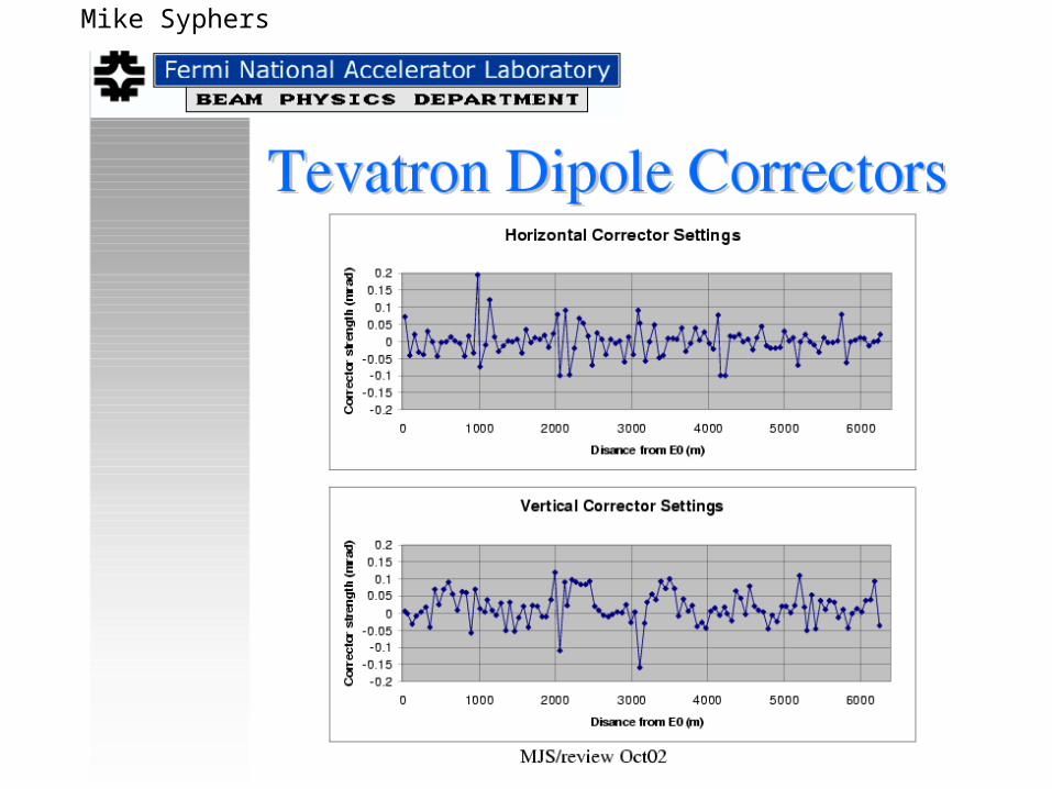
• We want to monitor corrector magnet settings more closely to follow changes as they occur from store to store. Use of SDA.

Elevations
The Tevatron now has a vertical network, tied to the Lab coordinates.
A1 under repair today.A14-1 may be an example.
B Sector
40.20
40.30
40.40
40.50
40.60
40.70
40.80
40.90
1,100 1,300 1,500 1,700 1,900
Z(m)
ele
va
tio
n (
inc
he
s)
B14-1B15-1B16-1B16-2B16-3B16-4B16-5B17-1B17-4B17-5B18-1B18-2B18-3B18-4B18-5B19-1B19-2B19-3B19-4B19-5B21-1B36-1B37-1B38-1all quadsB15-2B15-3B15-4B21-2B21-3B21-4B22-1B22-2B22-3B22-4B22-5B23-1B23-2B23-3B23-4B23-5B24-1B24-2B24-3B24-4B24-5B25-1B25-2B25-3B25-4B25-5B26-1B27-1B28-1B32-1B33-1B34-1B35-1
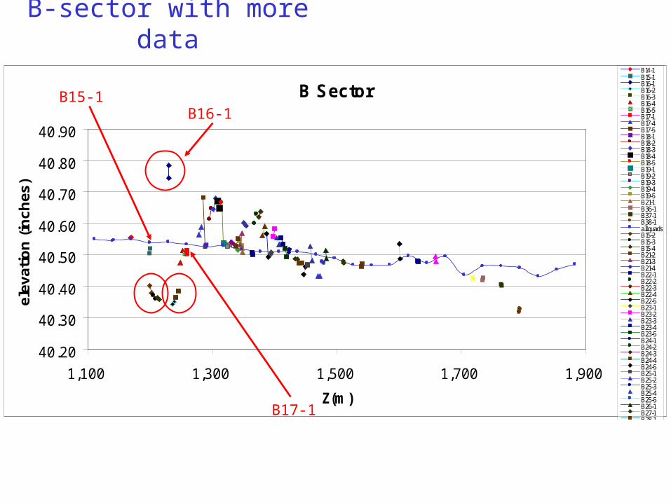
B-sector with more data
B15-1B16-1
B17-1
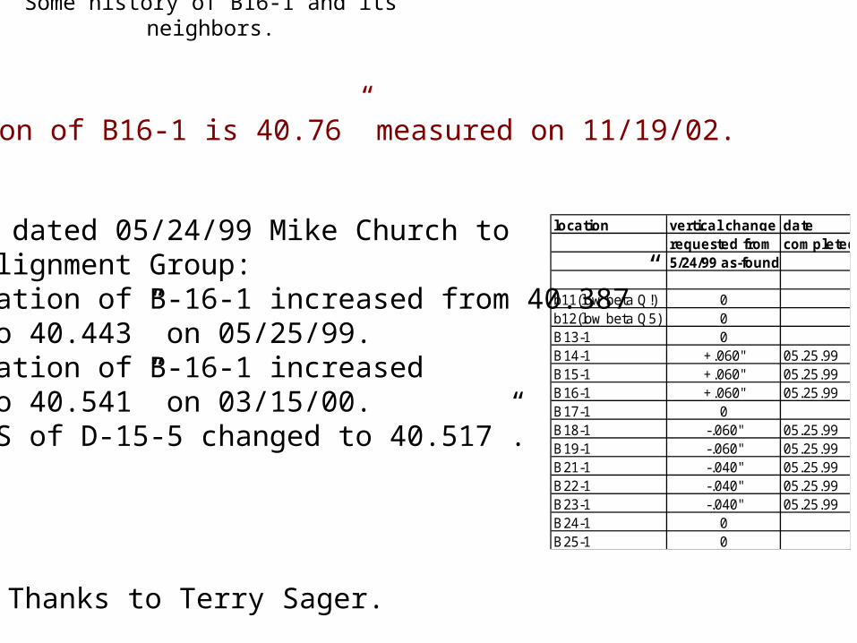
Some history of B16-1 and its neighbors.
• Memo dated 05/24/99 Mike Church to Alignment Group:
• Elevation of B-16-1 increased from 40.387”to 40.443” on 05/25/99.
• Elevation of B-16-1 increasedto 40.541” on 03/15/00.US of D-15-5 changed to 40.517”.
location vertical change daterequested from completed5/24/99 as-found
b11(low beta Q!) 0b12(low beta Q5) 0B13-1 0B14-1 +.060" 05.25.99B15-1 +.060" 05.25.99B16-1 +.060" 05.25.99B17-1 0B18-1 -.060" 05.25.99B19-1 -.060" 05.25.99B21-1 -.040" 05.25.99B22-1 -.040" 05.25.99B23-1 -.040" 05.25.99B24-1 0B25-1 0
Elevation of B16-1 is 40.76” measured on 11/19/02.
Thanks to Terry Sager.

Aperture Scan 01/07/03
Aperture Scan looks ok!
Typical Tev apertures:Quad 3 inchDipole 2.7 inchC0 lambs ~1 inchB16-1 = 1.36 inch
Thanks to Dan Bollinger and Todd Johnson.

CHAURIZE, SALAH J. 03/05/2003
A14-1 Quad
A14-2 Dipole
Spool to Dipole
Quad to Spool
Example of mismatch in elevation.
Spool
Quad to Spool toDipole interface.
Survey and realignment in this area is presently taking place.

A0 to A1
40.55
40.60
40.65
40.70
40.75
40.80
40.85
40.90
100 150 200 250 300
Z (m)
Ele
vati
on
(in
ch)
A15-2
A15-3
A15-4
A15-5
All Quads
A16-1
A18-1
A18-2
A18-3
A18-4
A18-5
Elevation Data at A0 and A1
We really have insufficient data on elevations. We may be missing some important discrepancies.
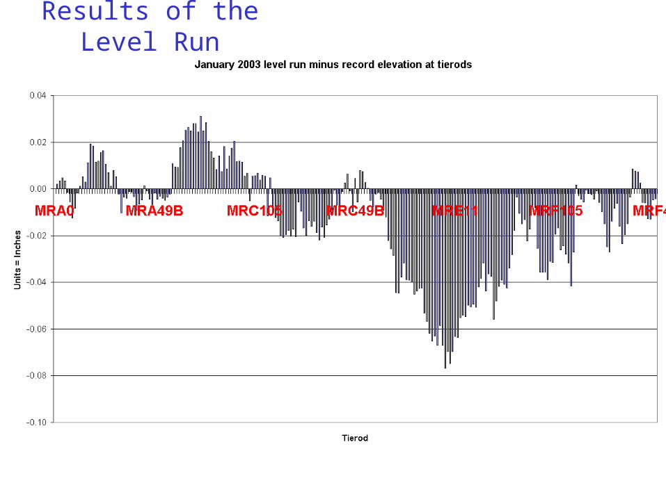
Results of the Level Run

B-sector elevation corrections
B-Sector Elevations
40.25
40.30
40.35
40.40
40.45
40.50
40.55
40.60
40.65
40.70
40.75
40.80
1100 1350 1600 1850
Z (m)
Ele
3vat
ion
s (i
nch
)
ElevationsCorrected Elevations1995 Quad Elevations
Shift is 17.5 mils
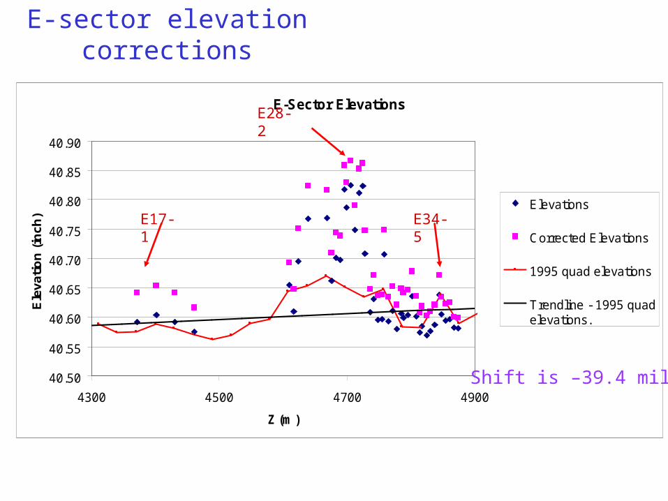
E-Sector Elevations
R2 = 0.1067
40.50
40.55
40.60
40.65
40.70
40.75
40.80
40.85
40.90
4300 4500 4700 4900
Z (m)
Ele
vati
on
(in
ch)
Elevations
Corrected Elevations
1995 quad elevations
Trendline - 1995 quadelevations.
E-sector elevation corrections
E28-2
E17-1 E34-5
Shift is –39.4 mils
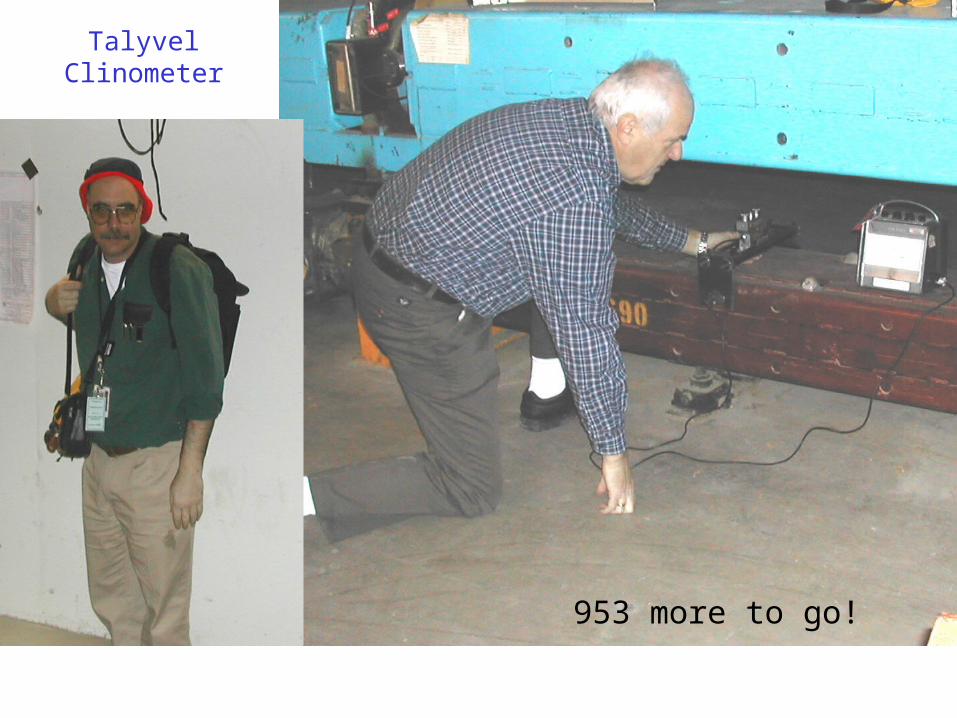
Talyvel Clinometer
953 more to go!

Comparison with Survey Data
0
1
2
3
4
5
6
7
8
9
10
Difference in mrad
Fixture vs Jun 02 data
Fixture vs Jan 03 data
Comparison with Survey Data
-6
-4
-2
0
2
4
6
8
10
250 300 350 400 450 500
Z (m)
Ro
ll (
mra
d)
01-Jan-03 (Hans)
14-Jun-02 (fixture)
24-Jan-03 (elevations)
A19 to A 26
-1.813.02
1.784-1.522
outliers
A Jun 2002 -0.0263 0.2063063 A Dec 2002 0.0181 0.1300

Sector Date Ave. Standard Diff. Deviation
A Nov 2001 -0.2000 0.1537 A Jun 2002 -0.0263 0.2063 A Dec 2002 0.0181 0.1300
B May 2000 -0.3162 0.1140 B Nov 2001 -0.0326 0.0843 B Dec 2002 0.0264 0.0682
C Nov 2001 -0.2245 0.0864
D May 2000 -0.3167 0.1211 D Nov2001 -0.2337 0.1039 D Feb 2003 0.0890 0.1275
E Nov 2001 -0.3459 0.1912 E Dec 2003 0.0759 0.1068
F Nov 2001 -0.3331 0.0704
Comprehensive Comparisonwith Survey
Some outliers

Roll vs Corrector
-0.20
-0.10
0.00
0.10
0.20
-4 -2 0 2 4 6 8 10
Roll
Co
rre
cto
r a
ng
le
Correlation – Roll vs MFGHorizontal Correctors vs Roll
-0.20
-0.10
0.00
0.10
0.20
-4 -2 0 2 4 6 8 10
Roll (mrad)
MF
G (
mra
d)
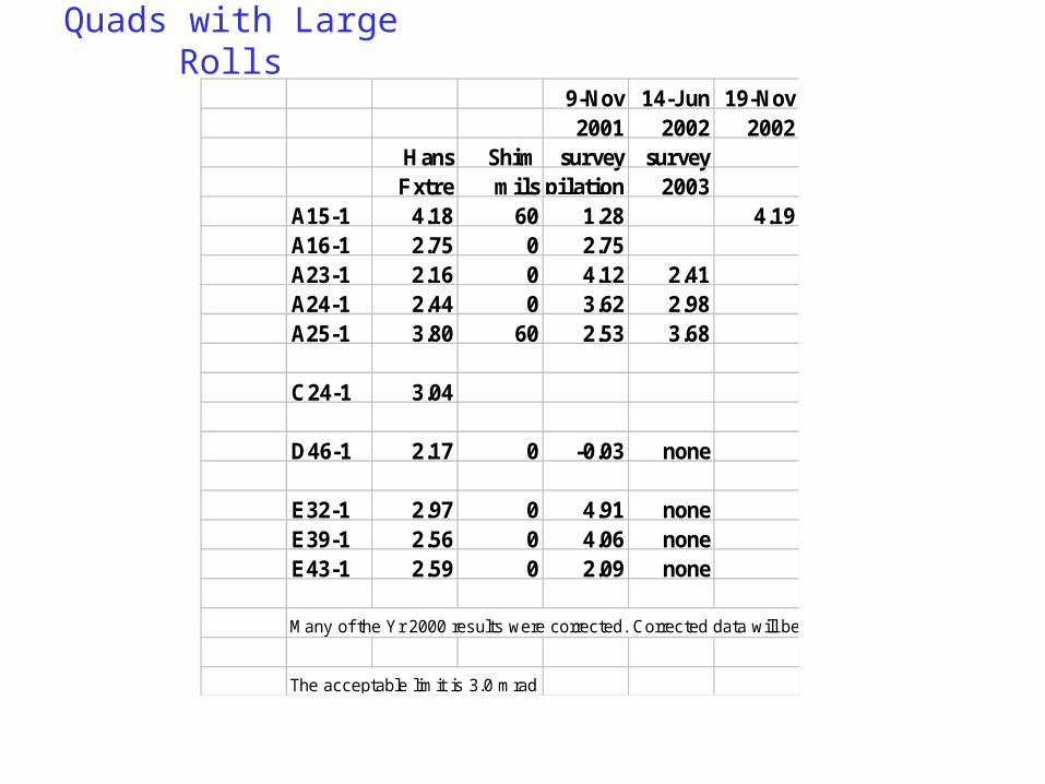
Quads with Large Rolls
9-Nov 14-Jun 19-Nov2001 2002 2002
Hans Shim survey surveyFxtre milscompilation 2003
A15-1 4.18 60 1.28 4.19A16-1 2.75 0 2.75A23-1 2.16 0 4.12 2.41A24-1 2.44 0 3.62 2.98A25-1 3.80 60 2.53 3.68
C24-1 3.04
D46-1 2.17 0 -0.03 none
E32-1 2.97 0 4.91 noneE39-1 2.56 0 4.06 noneE43-1 2.59 0 2.09 none
Many of the Yr 2000 results were corrected. Corrected data will be added soon.
The acceptable limit is 3.0 mrad.

TwistMagnet Twist
-5
-4
-3
-2
-1
0
1
2
3
0 1000 2000 3000 4000 5000 6000
Z (m)
Tw
ists
(m
rad
)
A21-3 2.97A21-4 1.18A29-4 1.14B13-2 -1.03B15-3 1.64B16-5 1.15B37-2 2.13C10-4 -2.11C14-5 1.03C15-2 -1.25C16-2 -1.21C17-5 -1.01C24-2 -1.17C47-1 -1.11D16-1 1.13E19-2 1.41E26-1 1.01E26-3 -1.16E28-4 -4.63E29-5 1.98F12-4 -1.2
Magnets with twistGreater than 1 mrad.

-4
-2
0
2
4
6
8
10
0 1000 2000 3000 4000 5000 6000 7000
Z (m)
Ro
ll (m
rad
)
MR Dipoles Removed
Dipooles Present
All TeV Magnets
Effect of MR Magnet Removal
MR not MRRemoved Removedmrad mrad
504 445
0.576 0.613
0.013 0.010
Total TeV magnets
Mean
Standard Deviation
Status of Nearby Directly Above and Main Ring Magnets Above on Either Side Removed 13(61.9%) 38(64.4%) Remaining 8(38.1%) 21(35.6%)
Roll:
Twist:

Location Roll (mrad)A15-1 4.176279A15-4 5.689188A18-3 4.100939A19-2 6.638064A21-2 7.931061A21-3 6.858994A214 4.875719A22-5 4.131482A23-3 3.835213A23-5 4.634428A24-5 3.668243A25-1 3.803651B16-1 Poor elevationB22-3 4.311687 3 SHIM RIB22-4 3.249801 3 SHIM RIB25-2 3.957386 3 SHIM RIC15-4 4.827868 3 SHIM RIC24-1 3.04007 3 SHIM RID46-4 5.31656 REPEAT WITH 1/8 INCH SHIM
Pockets of Interest
A21-3 2.97A21-4 1.18A29-4 1.14B13-2 -1.03B15-3 1.64B16-5 1.15B37-2 2.13C10-4 -2.11C14-5 1.03C15-2 -1.25C16-2 -1.21C17-5 -1.01C24-2 -1.17C47-1 -1.11D16-1 1.13E19-2 1.41E26-1 1.01E26-3 -1.16E28-4 -4.63E29-5 1.98F12-4 -1.2
Magnets with twistGreater than 1 mrad.

Number ofSector Magnets
Measured>1 >2 >3 >4 >5 >6 >7 in sector.
A 42 24 12 9 4 3 1 163
B 41 16 3 1 161
C 14 4 2 1 154
D 16 5 1 1 1 156
E 47 18 163
F 6 156
Total > N 166 67 18 12 5 3 1 953
Roll Angle > N mrad
Distribution of larger rolls in the
Tevatron.
17.4% have rolls> 1 mrad.
No. ofSector Magnets
Measured>1 >2 >3 >4 >5 >6 >7 in sector.
A 25.3% 35.8% 66.7% 75.0% 80.0% 100.0% 100.0% 163
B 24.7% 23.9% 16.7% 8.3% 161
C 8.4% 6.0% 11.1% 8.3% 154
D 9.6% 7.5% 5.6% 8.3% 20.0% 156
E 28.3% 26.9% 0.0% 0.0% 163
F 3.6% 0.0% 0.0% 0.0% 156
17.4% 7.0% 1.9% 1.3% 0.5% 0.3% 0.1% 1166 67 18 12 5 3 1 953
Roll Angle > N mrad
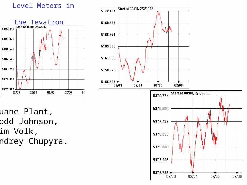
Level Meters in the
Tevatron
Duane Plant,Todd Johnson,Jim Volk,Andrey Chupyra.

Continuous relative elevation monitor.

A16-3&4 water level differnence
120.0
122.0
124.0
126.0
128.0
130.0
132.0
134.0
136.0
138.0
140.0
2/11/03 0:00 2/12/03 0:00 2/13/03 0:00 2/14/03 0:00 2/15/03 0:00 2/16/03 0:00 2/17/03 0:00 2/18/03 0:00
date
mic
rom
eter
s store 2213
Store 2229
Store 2231
Store 2232
A16-3 and A16-4 WLMJim Volk
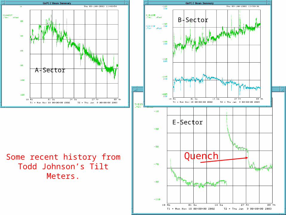
Quench
E-Sector
A-Sector
B-Sector
Some recent history from Todd Johnson’s Tilt Meters.

Have the Tev magnet coils moved in the ensuing years?
We measure significant differences in roll betweenthe us and ds ends of many magnets. The alignment lugs were originally set to account for any magnet twist:
Both ends of the magnet should have the same roll.Twist may be induced by 4-point stands.
There are several things we can do:a. Measure smart bolt settings (will be done tomorrow on a select set of magnets in the tunnel).b. Use the Kaiser coil to check for magnet coil alignment.c. There are about 24 magnets in storage that could be put on a stand and checked.
Coupling in the Tevatron

Tev Magnet cross section

Quadrant 2 Cold Lift Differences
-0.015
-0.010
-0.005
0.000
0.005
0.010
0.015
0.020
1 2 3 4 5 6 7 8 9
Support Number
DIf
fere
nc
e (
in)
TC0527
TB0277
TB0299
TB0338
TB0328
TC0468
TB0365
TB0351
TB1122
TB0596
TC0488
TC0531
TB0862
TC1218
TC0816
TC1059
TC0788
TC1149
Dipole Smart Bolt Measurements
-0.020
-0.015
-0.010
-0.005
0.000
0.005
0.010
0.015
0.020
0.025
0.030
0.035
1 11 21 31 41 51 61 71 81 91 101
111
121
131
141
151
161
Magnet
Mil
s Quadrant 1
Quadrant 2
Smart Bolt Survey in Tevatron
Measurements taken on 2/1982 and 2/18/2003.
Dave Harding, John Carlson,Jamie Blowers,And many others.
Would induce oneUnit of a1.

Coupling Study @ 150 GeV
• Beam mis-steered in P1 line
• T:SQ global skew quad circuit at 0 amps
• Look at betatron oscillation coupling between horz & vert
• Below are ~ 4 turns of data; 1st turn on left; scale limits 4mm
Horizontal
Vertical
Ron Moore

This is where we need to get creative.
• We need to measure magnet positions often, at least once per year. To follow changes as they take place, we should monitor what
magnets are doing over time. Keep track of changes in corrector magnet currents. The tilt monitors give a measure of short term changes:
We need a cheap way to put 1,000 of these in the ring. Hans Jostlein has come up with a quick roll measuring device:
We hope to be able to do the entire ring in 2-3 days. In a similar vein, we’ll need some way to quickly
measure elevation. Horizontal position checks would be useful also.
How do we manage the baseline configuration?

Summary
• A BD is being developed for Tevatron magnets to include magnetic fields and alignment data.• We need to complete elevation measurements. A14-1 was a revelation.• A horizontal survey network is in the design stage.• A continuous position monitoring system is being developed.• What can we say about twist.• We may want to realign shims within the iron yoke magnets.


