Beechcraft Bonanza 15e ARF Assembly Manual Specifications Wingspan: 48.0 in (1220mm) Length: 41.9 in (1065mm) Wing Area: 410 sq in (26.4 sq dm) Weight w/Battery: 4.20 – 4.50 lb (1.90 – 2.0 kg) Weight w/o Battery: 3.50 – 3.80 lb (1.50 – 1.60 kg) Cockpit Detail Kit (EFL2582), 1/9 Civilian Pilot Blue with Glasses (EFLA156) and 1/9 Civilian Pilot (EFLA151) all sold separately.
Transcript
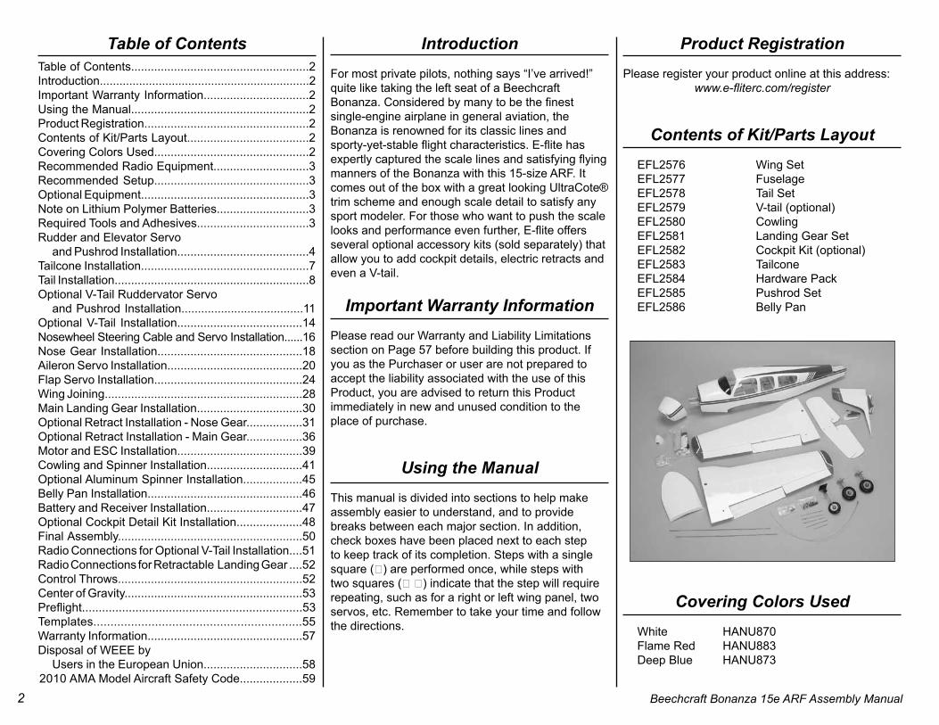
Beechcraft Bonanza 15e ARFAssembly Manual
Specifications
Wingspan: 48.0 in (1220mm)Length: 41.9 in (1065mm)Wing Area: 410 sq in (26.4 sq dm)Weight w/Battery: 4.20 – 4.50 lb (1.90 – 2.0 kg)Weight w/o Battery: 3.50 – 3.80 lb (1.50 – 1.60 kg)
Cockpit Detail Kit (EFL2582), 1/9 Civilian Pilot Blue with Glasses (EFLA156) and 1/9 Civilian Pilot (EFLA151) all sold separately.
2 Beechcraft Bonanza 15e ARF Assembly Manual
Table of ContentsTable of Contents......................................................2 Introduction................................................................2Important Warranty Information................................2Using the Manual......................................................2Product Registration..................................................2Contents of Kit/Parts Layout.....................................2Covering Colors Used...............................................2Recommended Radio Equipment.............................3Recommended Setup...............................................3Optional Equipment...................................................3Note on Lithium Polymer Batteries............................3Required Tools and Adhesives..................................3Rudder and Elevator Servo and Pushrod Installation........................................4Tailcone Installation...................................................7Tail Installation...........................................................8Optional V-Tail Ruddervator Servo and Pushrod Installation.....................................11Optional V-Tail Installation......................................14Nosewheel Steering Cable and Servo Installation......16Nose Gear Installation............................................18Aileron Servo Installation.........................................20Flap Servo Installation.............................................24Wing Joining............................................................28Main Landing Gear Installation................................30Optional Retract Installation - Nose Gear.................31Optional Retract Installation - Main Gear.................36Motor and ESC Installation......................................39Cowling and Spinner Installation.............................41Optional Aluminum Spinner Installation..................45Belly Pan Installation...............................................46Battery and Receiver Installation.............................47Optional Cockpit Detail Kit Installation....................48Final Assembly........................................................50Radio Connections for Optional V-Tail Installation....51Radio Connections for Retractable Landing Gear ....52Control Throws........................................................52Center of Gravity......................................................53Preflight..................................................................53Templates.............................................................55Warranty Information...............................................57Disposal of WEEE by Users in the European Union..............................582010 AMA Model Aircraft Safety Code...................59
IntroductionFor most private pilots, nothing says “I’ve arrived!” quite like taking the left seat of a Beechcraft Bonanza. Considered by many to be the finestsingle-engine airplane in general aviation, the Bonanza is renowned for its classic lines and sporty-yet-stable flight characteristics. E-flite has expertly captured the scale lines and satisfying flying manners of the Bonanza with this 15-size ARF. It comes out of the box with a great looking UltraCote® trim scheme and enough scale detail to satisfy any sport modeler. For those who want to push the scale looks and performance even further, E-flite offers several optional accessory kits (sold separately) that allow you to add cockpit details, electric retracts and even a V-tail.
Important Warranty InformationPlease read our Warranty and Liability Limitations section on Page 57 before building this product. If you as the Purchaser or user are not prepared to accept the liability associated with the use of this Product, you are advised to return this Product immediately in new and unused condition to the place of purchase.
Using the ManualThis manual is divided into sections to help makeassembly easier to understand, and to provide breaks between each major section. In addition, check boxes have been placed next to each step to keep track of its completion. Steps with a single square () are performed once, while steps with two squares ( ) indicate that the step will require repeating, such as for a right or left wing panel, two servos, etc. Remember to take your time and follow the directions.
Product RegistrationPlease register your product online at this address:
www.e-fliterc.com/register
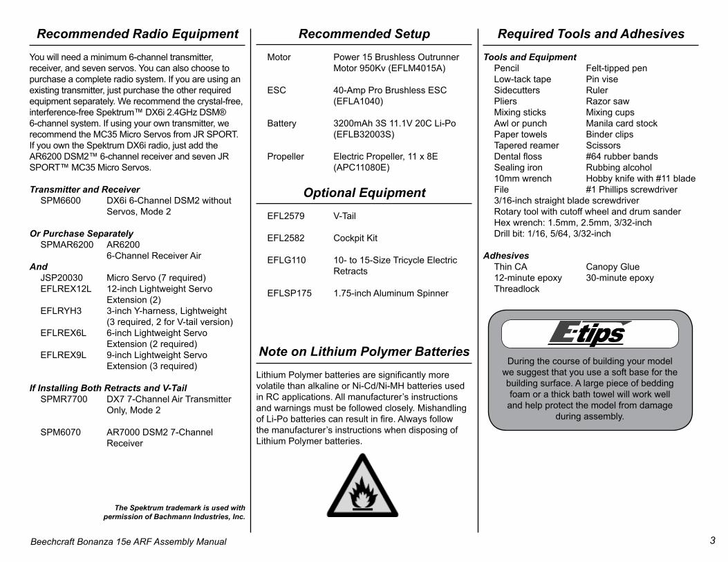
Contents of Kit/Parts Layout EFL2576 Wing Set EFL2577 Fuselage EFL2578 Tail Set EFL2579 V-tail (optional) EFL2580 Cowling EFL2581 Landing Gear Set EFL2582 Cockpit Kit (optional) EFL2583 Tailcone EFL2584 Hardware Pack EFL2585 Pushrod Set EFL2586 Belly Pan
Covering Colors Used White HANU870 Flame Red HANU883 Deep Blue HANU873
3Beechcraft Bonanza 15e ARF Assembly Manual
Recommended Radio EquipmentYou will need a minimum 6-channel transmitter,receiver, and seven servos. You can also choose topurchase a complete radio system. If you are using an existing transmitter, just purchase the other required equipment separately. We recommend the crystal-free, interference-free Spektrum™ DX6i 2.4GHz DSM® 6-channel system. If using your own transmitter, we recommend the MC35 Micro Servos from JR SPORT. If you own the Spektrum DX6i radio, just add the AR6200 DSM2™ 6-channel receiver and seven JR SPORT™ MC35 Micro Servos.
Transmitter and Receiver SPM6600 DX6i 6-Channel DSM2 without Servos, Mode 2
If Installing Both Retracts and V-Tail SPMR7700 DX7 7-Channel Air Transmitter Only, Mode 2
SPM6070 AR7000 DSM2 7-Channel Receiver
The Spektrum trademark is used with permission of Bachmann Industries, Inc.
Recommended Setup Motor Power 15 Brushless Outrunner Motor 950Kv (EFLM4015A)
ESC 40-Amp Pro Brushless ESC (EFLA1040)
Battery 3200mAh 3S 11.1V 20C Li-Po (EFLB32003S)
Propeller Electric Propeller, 11 x 8E (APC11080E)
Optional Equipment EFL2579 V-Tail
EFL2582 Cockpit Kit
EFLG110 10- to 15-Size Tricycle Electric Retracts
EFLSP175 1.75-inch Aluminum Spinner
Note on Lithium Polymer BatteriesLithium Polymer batteries are significantly more volatile than alkaline or Ni-Cd/Ni-MH batteries used in RC applications. All manufacturer’s instructions and warnings must be followed closely. Mishandling of Li-Po batteries can result in fire. Always follow the manufacturer’s instructions when disposing of Lithium Polymer batteries.
Required Tools and AdhesivesTools and Equipment Pencil Felt-tipped pen Low-tack tape Pin vise Sidecutters Ruler Pliers Razor saw Mixing sticks Mixing cups Awl or punch Manila card stock Paper towels Binder clips Tapered reamer Scissors Dental floss #64 rubber bands Sealing iron Rubbing alcohol 10mm wrench Hobby knife with #11 blade File #1 Phillips screwdriver 3/16-inch straight blade screwdriver Rotary tool with cutoff wheel and drum sander Hex wrench: 1.5mm, 2.5mm, 3/32-inch Drill bit: 1/16, 5/64, 3/32-inch
Adhesives Thin CA Canopy Glue 12-minute epoxy 30-minute epoxy Threadlock
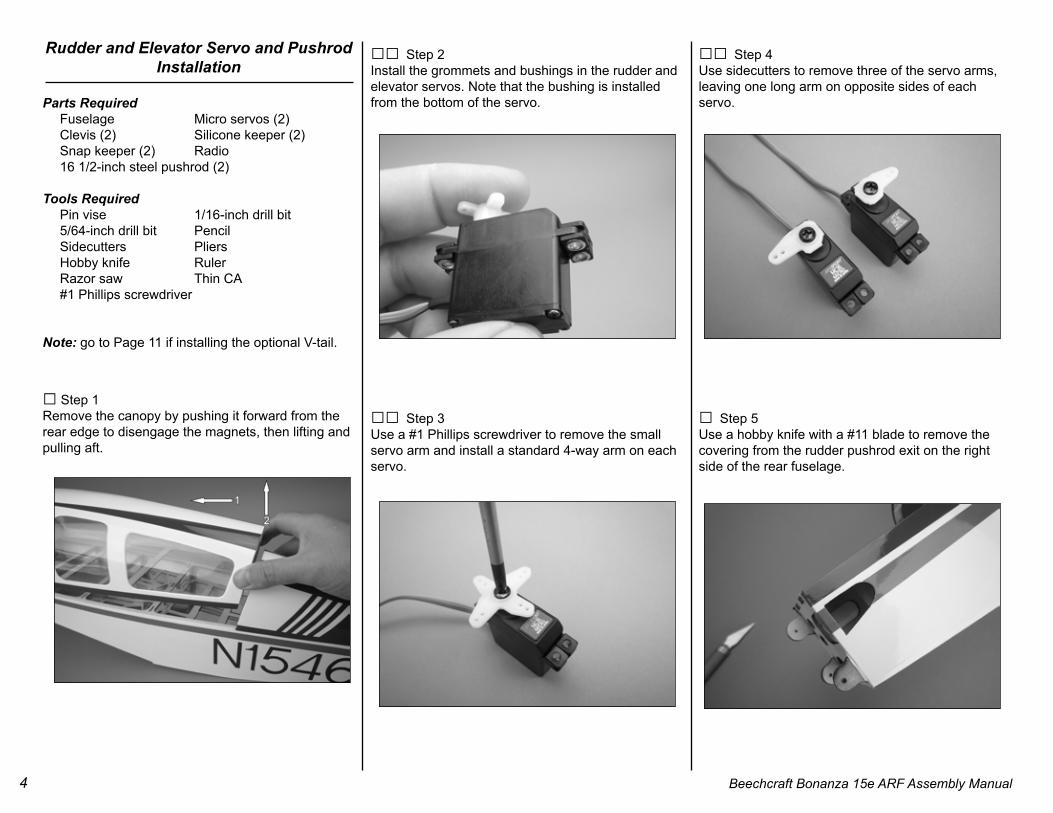
During the course of building your model we suggest that you use a soft base for the building surface. A large piece of beddingfoam or a thick bath towel will work well
and help protect the model from damage during assembly.
4 Beechcraft Bonanza 15e ARF Assembly Manual
Rudder and Elevator Servo and Pushrod Installation
Parts Required Fuselage Micro servos (2) Clevis (2) Silicone keeper (2) Snap keeper (2) Radio 16 1/2-inch steel pushrod (2) Tools Required Pin vise 1/16-inch drill bit 5/64-inch drill bit Pencil Sidecutters Pliers Hobby knife Ruler Razor saw Thin CA #1 Phillips screwdriver
Note: go to Page 11 if installing the optional V-tail.
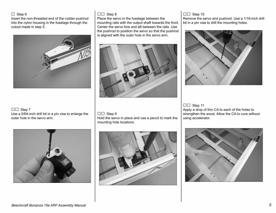
□ Step 1 Remove the canopy by pushing it forward from the rear edge to disengage the magnets, then lifting and pulling aft.
□□ Step 2 Install the grommets and bushings in the rudder and elevator servos. Note that the bushing is installed from the bottom of the servo.
□□ Step 3Use a #1 Phillips screwdriver to remove the small servo arm and install a standard 4-way arm on each servo.
□□ Step 4 Use sidecutters to remove three of the servo arms, leaving one long arm on opposite sides of each servo.
□ Step 5 Use a hobby knife with a #11 blade to remove the covering from the rudder pushrod exit on the right side of the rear fuselage.
5Beechcraft Bonanza 15e ARF Assembly Manual
□ Step 6 Insert the non-threaded end of the rudder pushrod into the nylon housing in the fuselage through the cutout made in step 5.
□□ Step 7 Use a 5/64-inch drill bit in a pin vise to enlarge the outer hole in the servo arm.
□□ Step 8 Place the servo in the fuselage between the mounting rails with the output shaft towards the front. Center the servo fore and aft between the rails. Use the pushrod to position the servo so that the pushrod is aligned with the outer hole in the servo arm.
□□ Step 9Hold the servo in place and use a pencil to mark the mounting hole locations.
□□ Step 10 Remove the servo and pushrod. Use a 1/16-inch drill bit in a pin vise to drill the mounting holes.
□□ Step 11 Apply a drop of thin CA to each of the holes to strengthen the wood. Allow the CA to cure without using accelerator.
6 Beechcraft Bonanza 15e ARF Assembly Manual
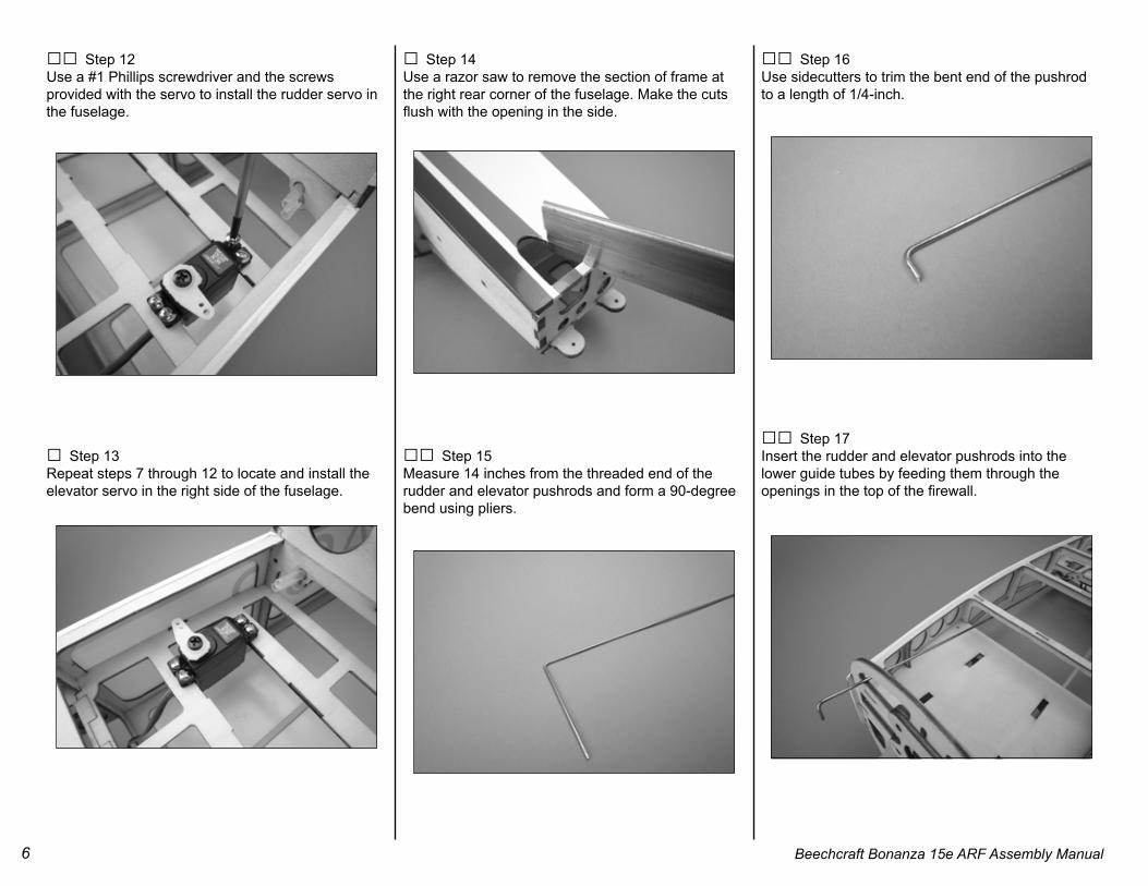
□□ Step 12 Use a #1 Phillips screwdriver and the screws provided with the servo to install the rudder servo in the fuselage.
□ Step 13Repeat steps 7 through 12 to locate and install the elevator servo in the right side of the fuselage.
□ Step 14 Use a razor saw to remove the section of frame at the right rear corner of the fuselage. Make the cuts flush with the opening in the side.
□□ Step 15 Measure 14 inches from the threaded end of the rudder and elevator pushrods and form a 90-degree bend using pliers.
□□ Step 16 Use sidecutters to trim the bent end of the pushrod to a length of 1/4-inch.
□□ Step 17 Insert the rudder and elevator pushrods into the lower guide tubes by feeding them through the openings in the top of the firewall.
7Beechcraft Bonanza 15e ARF Assembly Manual
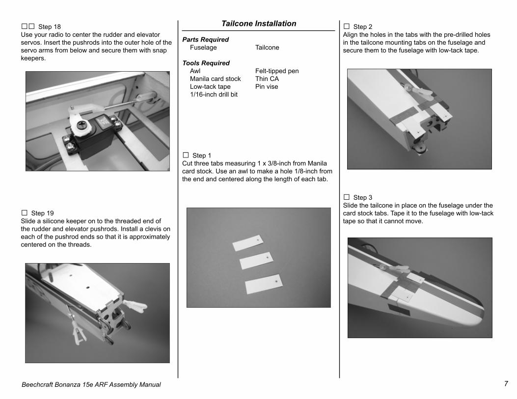
□□ Step 18 Use your radio to center the rudder and elevator servos. Insert the pushrods into the outer hole of the servo arms from below and secure them with snap keepers.
□ Step 19 Slide a silicone keeper on to the threaded end of the rudder and elevator pushrods. Install a clevis on each of the pushrod ends so that it is approximately centered on the threads.
Tailcone Installation
Parts Required Fuselage Tailcone
Tools Required Awl Felt-tipped pen Manila card stock Thin CA Low-tack tape Pin vise 1/16-inch drill bit
□ Step 1 Cut three tabs measuring 1 x 3/8-inch from Manila card stock. Use an awl to make a hole 1/8-inch from the end and centered along the length of each tab.
□ Step 2 Align the holes in the tabs with the pre-drilled holes in the tailcone mounting tabs on the fuselage and secure them to the fuselage with low-tack tape.
□ Step 3 Slide the tailcone in place on the fuselage under the card stock tabs. Tape it to the fuselage with low-tack tape so that it cannot move.
8 Beechcraft Bonanza 15e ARF Assembly Manual
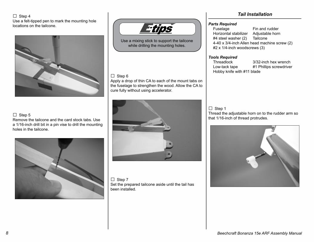
□ Step 4 Use a felt-tipped pen to mark the mounting hole locations on the tailcone.
□ Step 5 Remove the tailcone and the card stock tabs. Use a 1/16-inch drill bit in a pin vise to drill the mounting holes in the tailcone.
□ Step 6 Apply a drop of thin CA to each of the mount tabs on the fuselage to strengthen the wood. Allow the CA to cure fully without using accelerator.
□ Step 7 Set the prepared tailcone aside until the tail has been installed.
Tail Installation
Parts Required Fuselage Fin and rudder Horizontal stabilizer Adjustable horn #4 steel washer (2) Tailcone 4-40 x 3/4-inch Allen head machine screw (2) #2 x 1/4-inch woodscrews (3) Tools Required Threadlock 3/32-inch hex wrench Low-tack tape #1 Phillips screwdriver Hobby knife with #11 blade
□ Step 1 Thread the adjustable horn on to the rudder arm so that 1/16-inch of thread protrudes.
Use a mixing stick to support the tailcone while drilling the mounting holes.
9Beechcraft Bonanza 15e ARF Assembly Manual
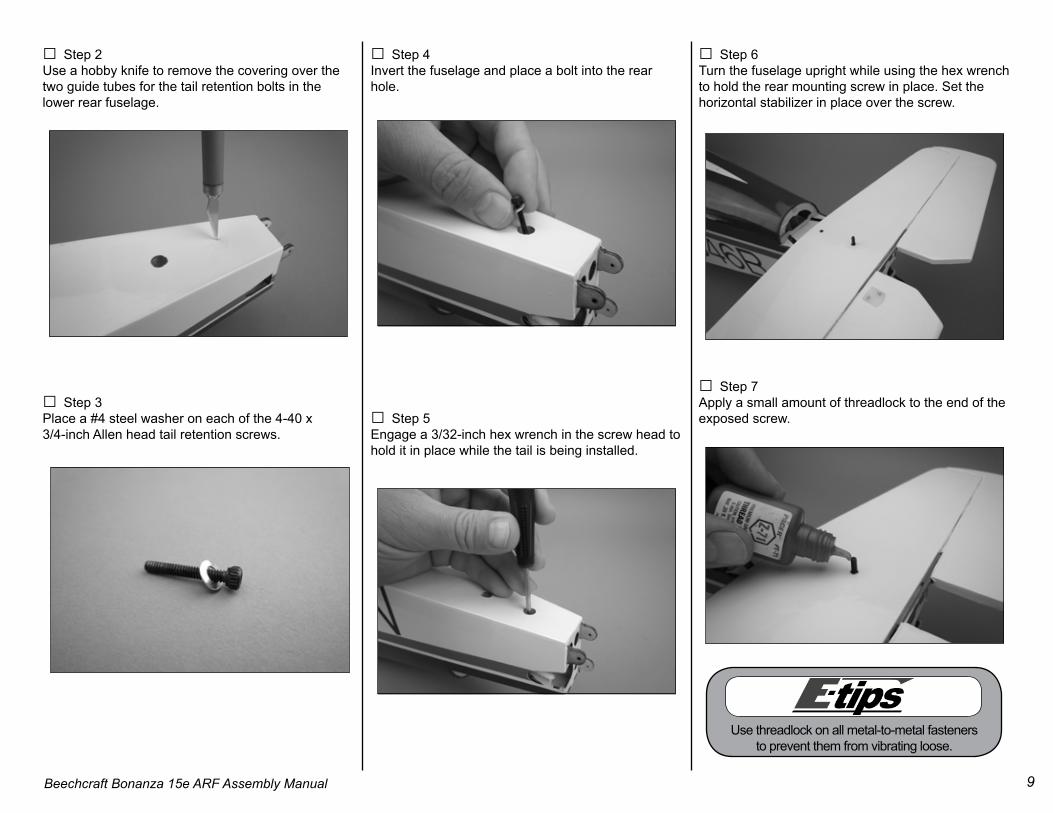
□ Step 2Use a hobby knife to remove the covering over the two guide tubes for the tail retention bolts in the lower rear fuselage.
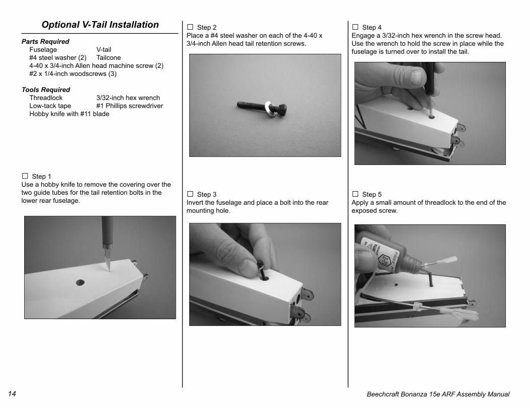
□ Step 3 Place a #4 steel washer on each of the 4-40 x 3/4-inch Allen head tail retention screws.
□ Step 4 Invert the fuselage and place a bolt into the rear hole.
□ Step 5 Engage a 3/32-inch hex wrench in the screw head to hold it in place while the tail is being installed.
□ Step 6 Turn the fuselage upright while using the hex wrench to hold the rear mounting screw in place. Set the horizontal stabilizer in place over the screw.
□ Step 7 Apply a small amount of threadlock to the end of the exposed screw.
Use threadlock on all metal-to-metal fasteners to prevent them from vibrating loose.
10 Beechcraft Bonanza 15e ARF Assembly Manual
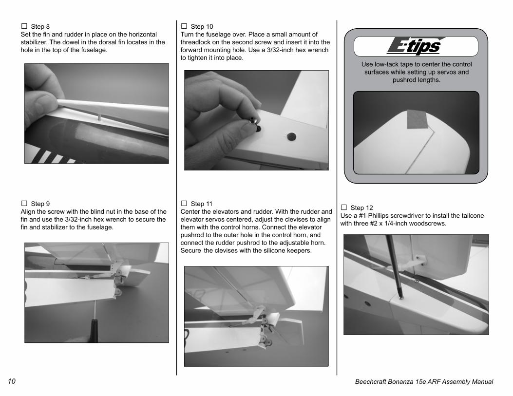
□ Step 8 Set the fin and rudder in place on the horizontal stabilizer. The dowel in the dorsal fin locates in the hole in the top of the fuselage.
□ Step 9Align the screw with the blind nut in the base of the fin and use the 3/32-inch hex wrench to secure the fin and stabilizer to the fuselage.
□ Step 10 Turn the fuselage over. Place a small amount of threadlock on the second screw and insert it into the forward mounting hole. Use a 3/32-inch hex wrench to tighten it into place.
□ Step 11Center the elevators and rudder. With the rudder and elevator servos centered, adjust the clevises to align them with the control horns. Connect the elevator pushrod to the outer hole in the control horn, and connect the rudder pushrod to the adjustable horn. Secure the clevises with the silicone keepers.
□ Step 12Use a #1 Phillips screwdriver to install the tailcone with three #2 x 1/4-inch woodscrews.
Use low-tack tape to center the control surfaces while setting up servos and
pushrod lengths.
11Beechcraft Bonanza 15e ARF Assembly Manual
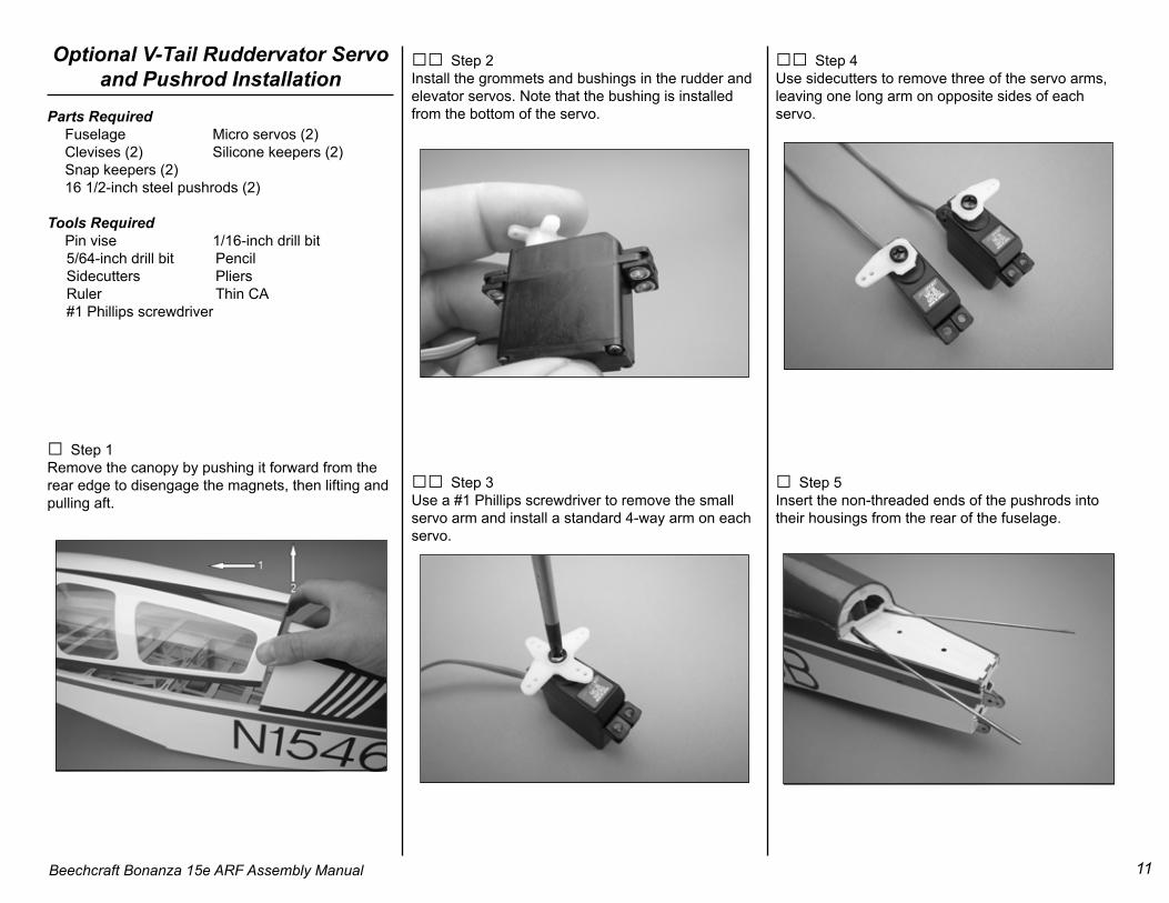
Optional V-Tail Ruddervator Servo and Pushrod Installation
Tools Required Pin vise 1/16-inch drill bit 5/64-inch drill bit Pencil Sidecutters Pliers Ruler Thin CA #1 Phillips screwdriver
□ Step 1Remove the canopy by pushing it forward from therear edge to disengage the magnets, then lifting andpulling aft.
□□ Step 4Use sidecutters to remove three of the servo arms,leaving one long arm on opposite sides of eachservo.
□ Step 5Insert the non-threaded ends of the pushrods into their housings from the rear of the fuselage.
□□ Step 2Install the grommets and bushings in the rudder andelevator servos. Note that the bushing is installedfrom the bottom of the servo.
□□ Step 3Use a #1 Phillips screwdriver to remove the smallservo arm and install a standard 4-way arm on eachservo.
12 Beechcraft Bonanza 15e ARF Assembly Manual
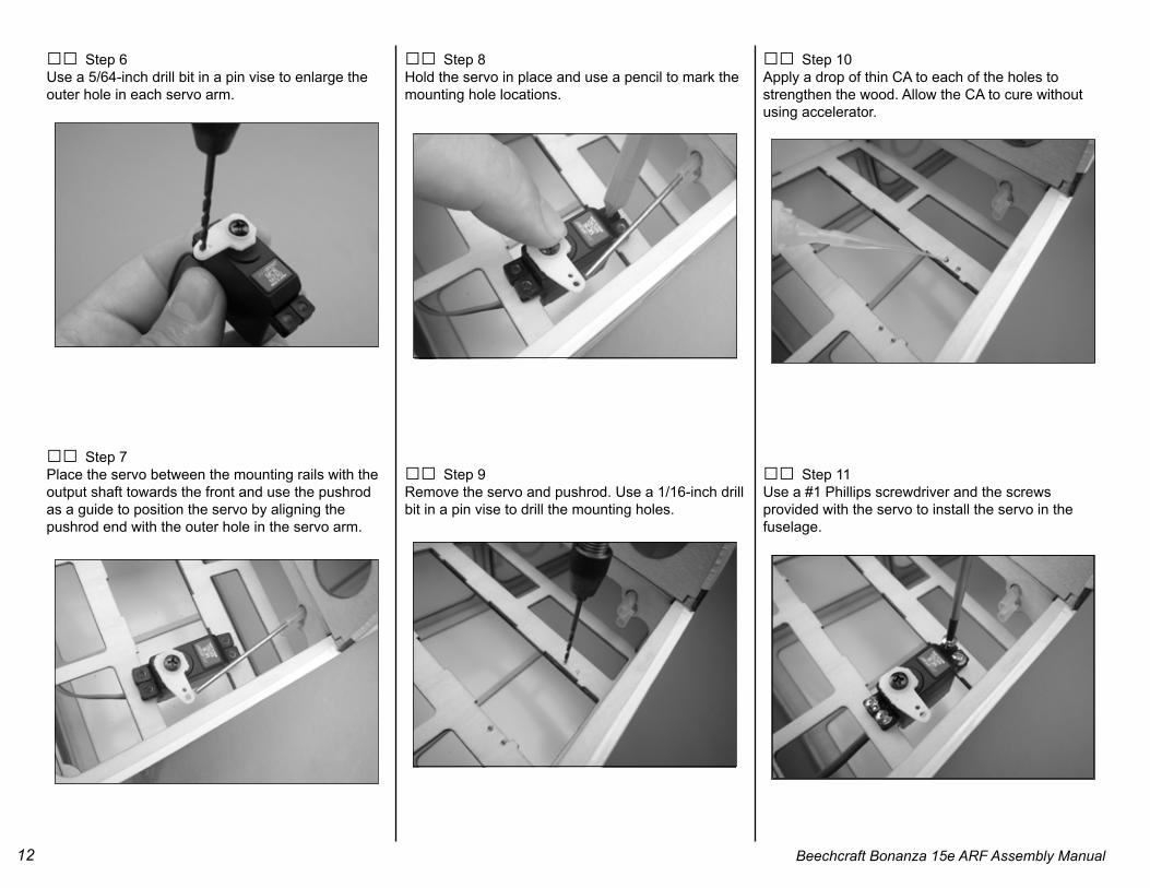
□□ Step 6Use a 5/64-inch drill bit in a pin vise to enlarge theouter hole in each servo arm.
□□ Step 7Place the servo between the mounting rails with the output shaft towards the front and use the pushrod as a guide to position the servo by aligning the pushrod end with the outer hole in the servo arm.
□□ Step 8Hold the servo in place and use a pencil to mark the mounting hole locations.
□□ Step 9Remove the servo and pushrod. Use a 1/16-inch drill bit in a pin vise to drill the mounting holes.
□□ Step 10Apply a drop of thin CA to each of the holes tostrengthen the wood. Allow the CA to cure withoutusing accelerator.
□□ Step 11Use a #1 Phillips screwdriver and the screwsprovided with the servo to install the servo in the fuselage.
13Beechcraft Bonanza 15e ARF Assembly Manual
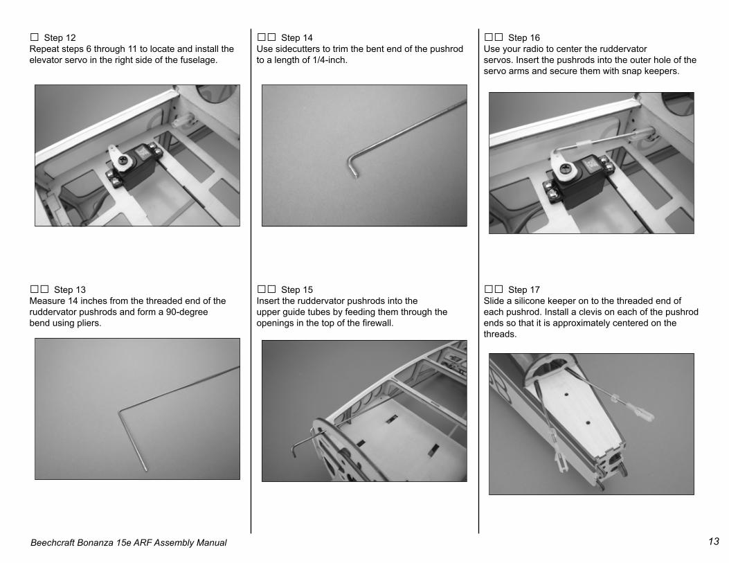
□ Step 12Repeat steps 6 through 11 to locate and install theelevator servo in the right side of the fuselage.
□□ Step 13Measure 14 inches from the threaded end of theruddervator pushrods and form a 90-degreebend using pliers.
□□ Step 14Use sidecutters to trim the bent end of the pushrodto a length of 1/4-inch.
□□ Step 15Insert the ruddervator pushrods into theupper guide tubes by feeding them through theopenings in the top of the firewall.
□□ Step 16Use your radio to center the ruddervatorservos. Insert the pushrods into the outer hole of theservo arms and secure them with snap keepers.
□□ Step 17Slide a silicone keeper on to the threaded end of each pushrod. Install a clevis on each of the pushrod ends so that it is approximately centered on the threads.
14 Beechcraft Bonanza 15e ARF Assembly Manual
Optional V-Tail InstallationParts Required Fuselage V-tail #4 steel washer (2) Tailcone 4-40 x 3/4-inch Allen head machine screw (2) #2 x 1/4-inch woodscrews (3)
□ Step 1Use a hobby knife to remove the covering over thetwo guide tubes for the tail retention bolts in thelower rear fuselage.
□ Step 2Place a #4 steel washer on each of the 4-40 x 3/4-inch Allen head tail retention screws.
□ Step 3Invert the fuselage and place a bolt into the rear mounting hole.
□ Step 4Engage a 3/32-inch hex wrench in the screw head. Use the wrench to hold the screw in place while the fuselage is turned over to install the tail.
□ Step 5Apply a small amount of threadlock to the end of theexposed screw.
15Beechcraft Bonanza 15e ARF Assembly Manual
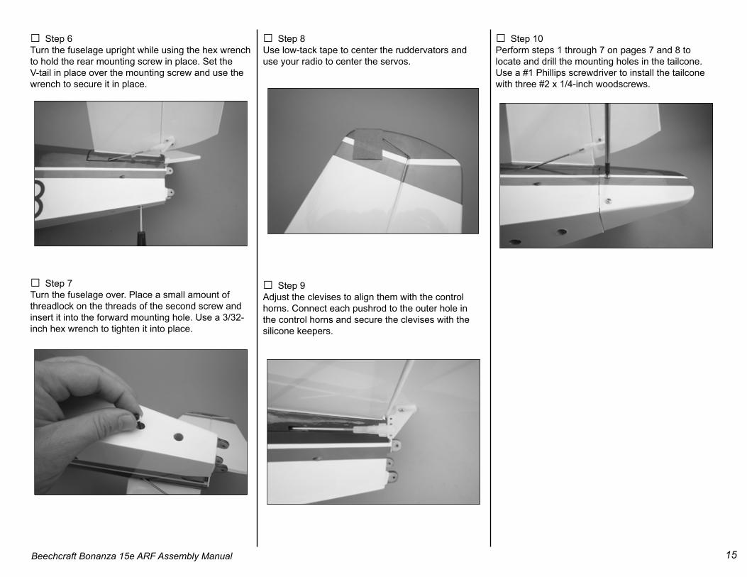
□ Step 6Turn the fuselage upright while using the hex wrench to hold the rear mounting screw in place. Set the V-tail in place over the mounting screw and use the wrench to secure it in place.
□ Step 7Turn the fuselage over. Place a small amount ofthreadlock on the threads of the second screw and insert it into the forward mounting hole. Use a 3/32-inch hex wrench to tighten it into place.
□ Step 8Use low-tack tape to center the ruddervators and use your radio to center the servos.
□ Step 9 Adjust the clevises to align them with the control horns. Connect each pushrod to the outer hole in the control horns and secure the clevises with the silicone keepers.
□ Step 10Perform steps 1 through 7 on pages 7 and 8 to locate and drill the mounting holes in the tailcone. Use a #1 Phillips screwdriver to install the tailcone with three #2 x 1/4-inch woodscrews.
16 Beechcraft Bonanza 15e ARF Assembly Manual
Nosewheel Steering Cable and Servo Installation
Parts Required Fuselage Micro servo (1) Steering cable Silicone keeper Pushrod connector and button keeper 17-inch nylon pushrod housing
Tools Required Pencil #1 Phillips screwdriver Canopy glue 3/32-inch drill bit Pin vise Thin CA Pliers Sidecutters
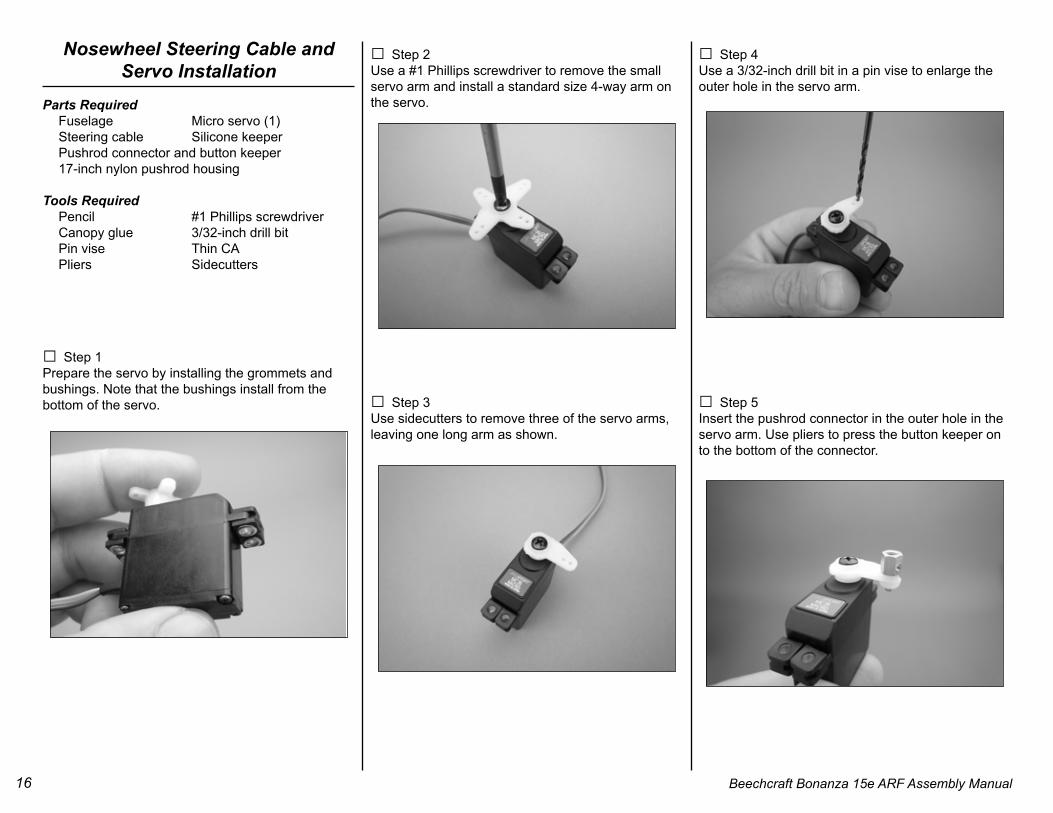
□ Step 1Prepare the servo by installing the grommets and bushings. Note that the bushings install from the bottom of the servo.
□ Step 2Use a #1 Phillips screwdriver to remove the small servo arm and install a standard size 4-way arm on the servo.
□ Step 3Use sidecutters to remove three of the servo arms, leaving one long arm as shown.
□ Step 4Use a 3/32-inch drill bit in a pin vise to enlarge the outer hole in the servo arm.
□ Step 5Insert the pushrod connector in the outer hole in the servo arm. Use pliers to press the button keeper on to the bottom of the connector.
17Beechcraft Bonanza 15e ARF Assembly Manual
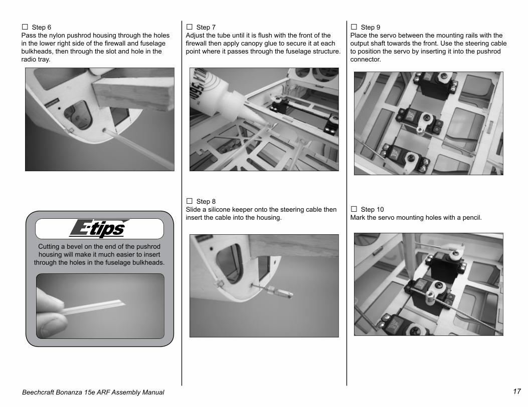
□ Step 6Pass the nylon pushrod housing through the holes in the lower right side of the firewall and fuselage bulkheads, then through the slot and hole in the radio tray.
□ Step 7Adjust the tube until it is flush with the front of the firewall then apply canopy glue to secure it at each point where it passes through the fuselage structure.
□ Step 8Slide a silicone keeper onto the steering cable then insert the cable into the housing.
□ Step 9Place the servo between the mounting rails with the output shaft towards the front. Use the steering cable to position the servo by inserting it into the pushrod connector.
□ Step 10Mark the servo mounting holes with a pencil.
Cutting a bevel on the end of the pushrod housing will make it much easier to insert
through the holes in the fuselage bulkheads.
18 Beechcraft Bonanza 15e ARF Assembly Manual
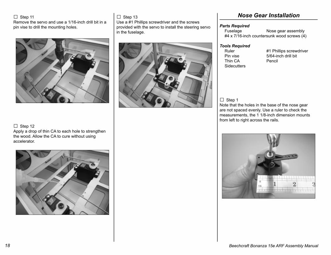
□ Step 11Remove the servo and use a 1/16-inch drill bit in a pin vise to drill the mounting holes.
□ Step 12Apply a drop of thin CA to each hole to strengthen the wood. Allow the CA to cure without using accelerator.
□ Step 13Use a #1 Phillips screwdriver and the screwsprovided with the servo to install the steering servo in the fuselage.
Nose Gear InstallationParts Required Fuselage Nose gear assembly #4 x 7/16-inch countersunk wood screws (4)
Tools Required Ruler #1 Phillips screwdriver Pin vise 5/64-inch drill bit Thin CA Pencil Sidecutters
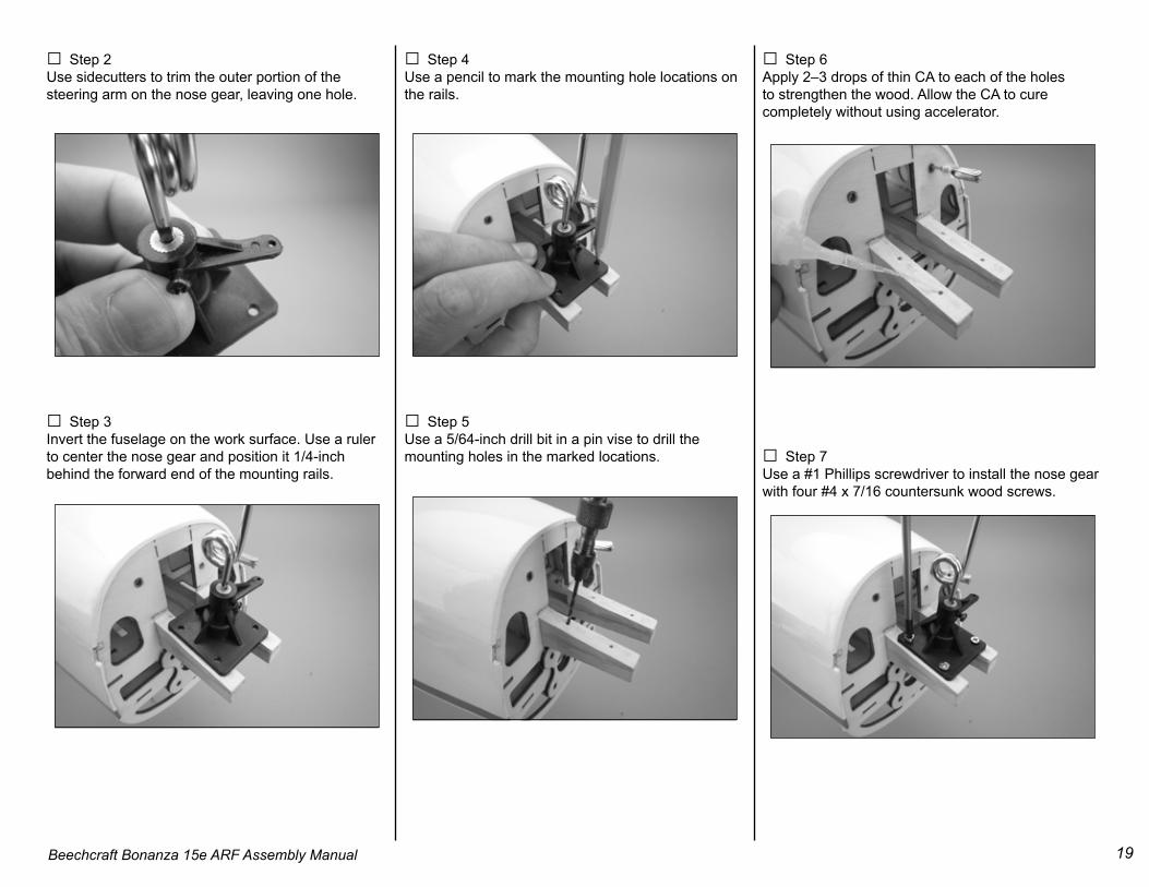
□ Step 1Note that the holes in the base of the nose gear are not spaced evenly. Use a ruler to check the measurements, the 1 1/8-inch dimension mounts from left to right across the rails.
19Beechcraft Bonanza 15e ARF Assembly Manual
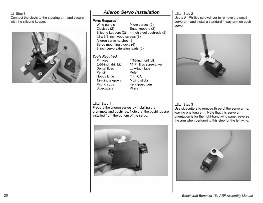
□ Step 2Use sidecutters to trim the outer portion of the steering arm on the nose gear, leaving one hole.
□ Step 3Invert the fuselage on the work surface. Use a ruler to center the nose gear and position it 1/4-inch behind the forward end of the mounting rails.
□ Step 4Use a pencil to mark the mounting hole locations on the rails.
□ Step 5Use a 5/64-inch drill bit in a pin vise to drill the mounting holes in the marked locations.
□ Step 6Apply 2–3 drops of thin CA to each of the holes to strengthen the wood. Allow the CA to cure completely without using accelerator.
□ Step 7Use a #1 Phillips screwdriver to install the nose gear with four #4 x 7/16 countersunk wood screws.
20 Beechcraft Bonanza 15e ARF Assembly Manual
□ Step 8Connect the clevis to the steering arm and secure it with the silicone keeper.
□□ Step 1Prepare the aileron servos by installing the grommets and bushings. Note that the bushings are installed from the bottom of the servo.
□□ Step 2Use a #1 Phillips screwdriver to remove the smallservo arm and install a standard 4-way arm on eachservo.
□□ Step 3Use sidecutters to remove three of the servo arms,leaving one long arm. Note that this servo arm orientation is for the right-hand wing panel, reverse the arm when performing this step for the left wing.
21Beechcraft Bonanza 15e ARF Assembly Manual
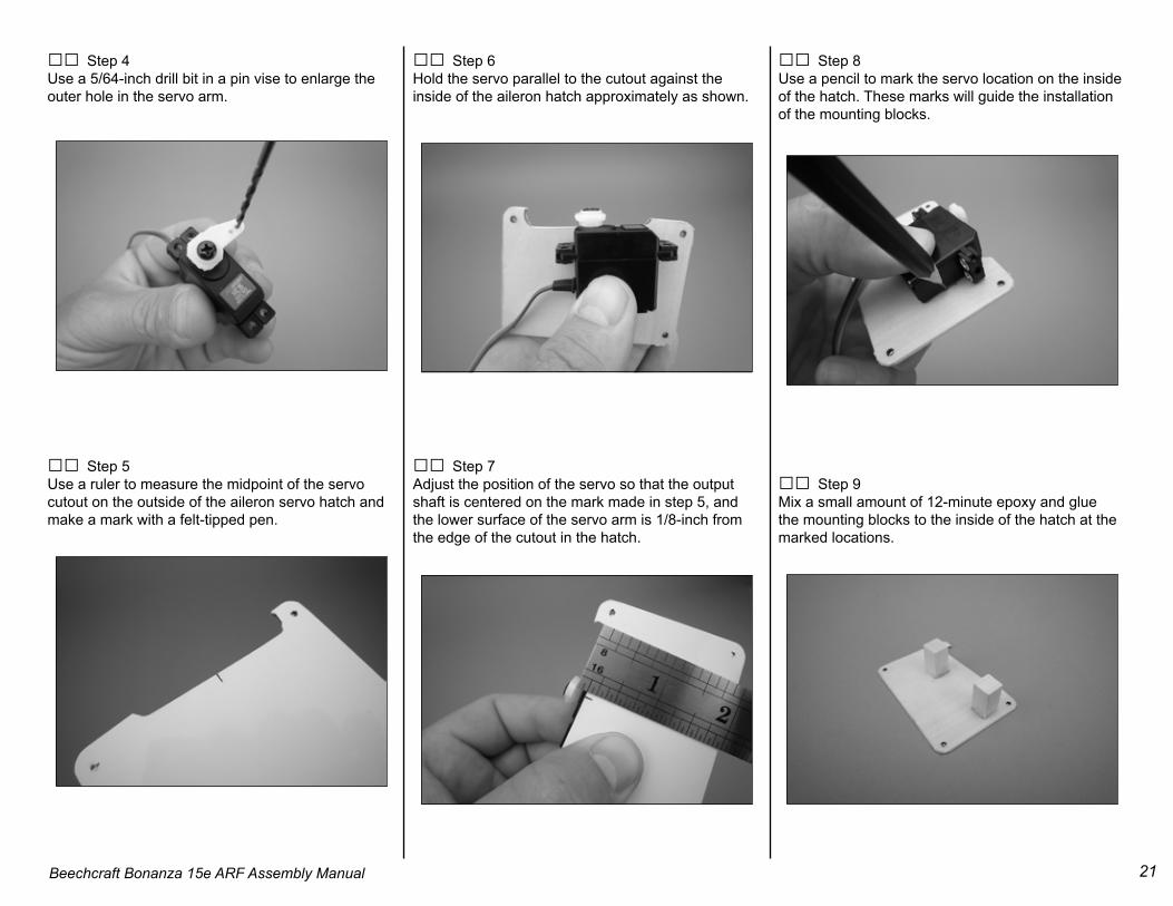
□□ Step 4Use a 5/64-inch drill bit in a pin vise to enlarge the outer hole in the servo arm.
□□ Step 5Use a ruler to measure the midpoint of the servo cutout on the outside of the aileron servo hatch and make a mark with a felt-tipped pen.
□□ Step 6Hold the servo parallel to the cutout against the inside of the aileron hatch approximately as shown.
□□ Step 7Adjust the position of the servo so that the output shaft is centered on the mark made in step 5, and the lower surface of the servo arm is 1/8-inch from the edge of the cutout in the hatch.
□□ Step 8Use a pencil to mark the servo location on the inside of the hatch. These marks will guide the installation of the mounting blocks.
□□ Step 9Mix a small amount of 12-minute epoxy and glue the mounting blocks to the inside of the hatch at the marked locations.
22 Beechcraft Bonanza 15e ARF Assembly Manual
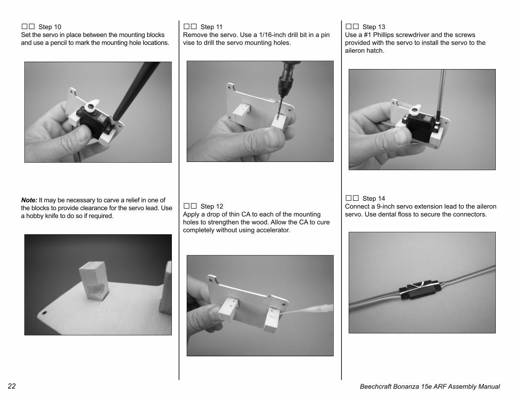
□□ Step 10Set the servo in place between the mounting blocks and use a pencil to mark the mounting hole locations.
Note: It may be necessary to carve a relief in one of the blocks to provide clearance for the servo lead. Use a hobby knife to do so if required.
□□ Step 11Remove the servo. Use a 1/16-inch drill bit in a pin vise to drill the servo mounting holes.
□□ Step 12Apply a drop of thin CA to each of the mounting holes to strengthen the wood. Allow the CA to cure completely without using accelerator.
□□ Step 13Use a #1 Phillips screwdriver and the screwsprovided with the servo to install the servo to the aileron hatch.
□□ Step 14Connect a 9-inch servo extension lead to the aileron servo. Use dental floss to secure the connectors.
23Beechcraft Bonanza 15e ARF Assembly Manual
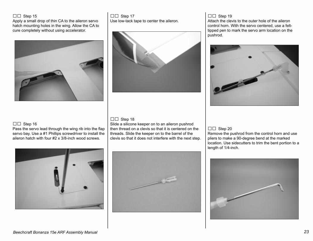
□□ Step 15Apply a small drop of thin CA to the aileron servo hatch mounting holes in the wing. Allow the CA to cure completely without using accelerator.
□□ Step 16Pass the servo lead through the wing rib into the flap servo bay. Use a #1 Phillips screwdriver to install the aileron hatch with four #2 x 3/8-inch wood screws.
□□ Step 17Use low-tack tape to center the aileron.
□□ Step 18Slide a silicone keeper on to an aileron pushrod then thread on a clevis so that it is centered on the threads. Slide the keeper on to the barrel of the clevis so that it does not interfere with the next step.
□□ Step 19Attach the clevis to the outer hole of the aileron control horn. With the servo centered, use a felt-tipped pen to mark the servo arm location on the pushrod.
□□ Step 20Remove the pushrod from the control horn and use pliers to make a 90-degree bend at the marked location. Use sidecutters to trim the bent portion to a length of 1/4-inch.
24 Beechcraft Bonanza 15e ARF Assembly Manual
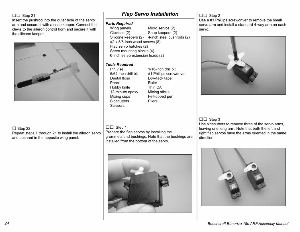
□□ Step 21Insert the pushrod into the outer hole of the servo arm and secure it with a snap keeper. Connect the clevis to the aileron control horn and secure it with the silicone keeper.
□ Step 22Repeat steps 1 through 21 to install the aileron servo and pushrod in the opposite wing panel.
□□ Step 1Prepare the flap servos by installing thegrommets and bushings. Note that the bushings areinstalled from the bottom of the servo.
□□ Step 2Use a #1 Phillips screwdriver to remove the smallservo arm and install a standard 4-way arm on eachservo.
□□ Step 3Use sidecutters to remove three of the servo arms,leaving one long arm. Note that both the left and right flap servos have the arms oriented in the same direction.
25Beechcraft Bonanza 15e ARF Assembly Manual
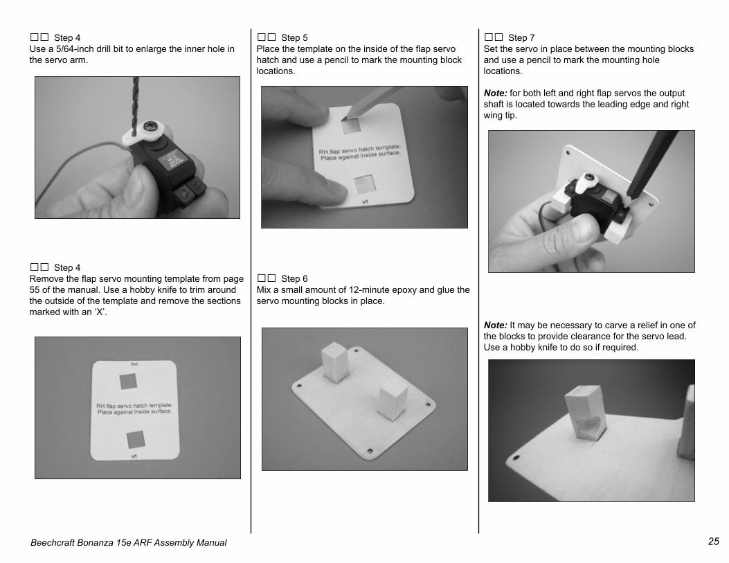
□□ Step 4Use a 5/64-inch drill bit to enlarge the inner hole in the servo arm.
□□ Step 4Remove the flap servo mounting template from page 55 of the manual. Use a hobby knife to trim around the outside of the template and remove the sections marked with an ‘X’.
□□ Step 5Place the template on the inside of the flap servo hatch and use a pencil to mark the mounting block locations.
□□ Step 6Mix a small amount of 12-minute epoxy and glue the servo mounting blocks in place.
□□ Step 7Set the servo in place between the mounting blocksand use a pencil to mark the mounting hole locations.
Note: for both left and right flap servos the output shaft is located towards the leading edge and right wing tip.
Note: It may be necessary to carve a relief in one of the blocks to provide clearance for the servo lead. Use a hobby knife to do so if required.
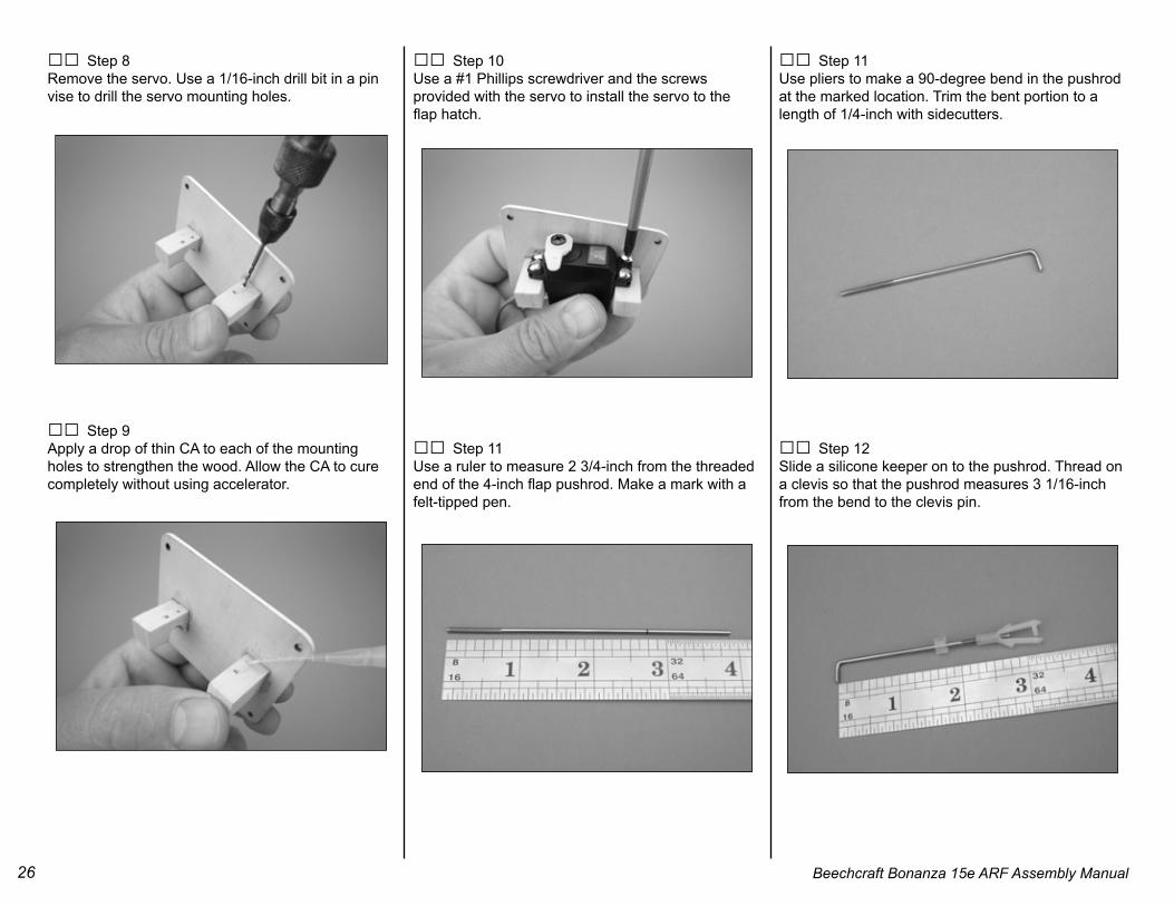
26 Beechcraft Bonanza 15e ARF Assembly Manual
□□ Step 8Remove the servo. Use a 1/16-inch drill bit in a pinvise to drill the servo mounting holes.
□□ Step 9Apply a drop of thin CA to each of the mountingholes to strengthen the wood. Allow the CA to curecompletely without using accelerator.
□□ Step 10Use a #1 Phillips screwdriver and the screwsprovided with the servo to install the servo to theflap hatch.
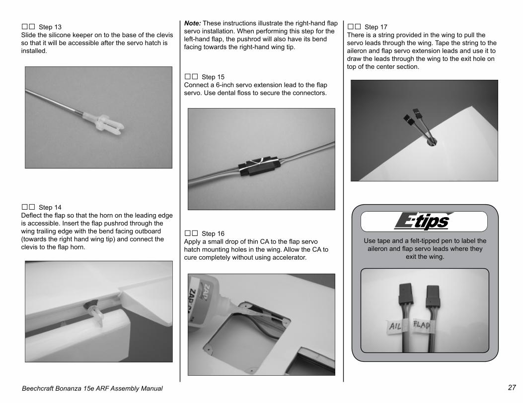
□□ Step 11Use a ruler to measure 2 3/4-inch from the threaded end of the 4-inch flap pushrod. Make a mark with a felt-tipped pen.
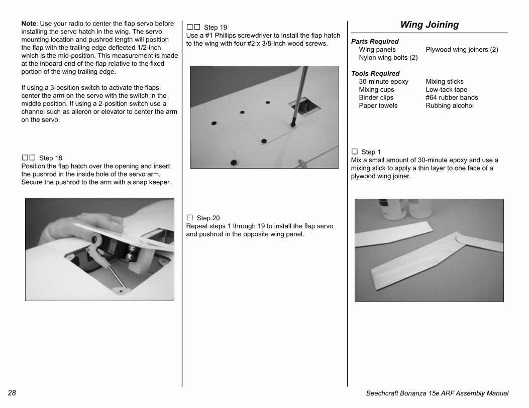
□□ Step 11Use pliers to make a 90-degree bend in the pushrod at the marked location. Trim the bent portion to a length of 1/4-inch with sidecutters.
□□ Step 12Slide a silicone keeper on to the pushrod. Thread on a clevis so that the pushrod measures 3 1/16-inch from the bend to the clevis pin.
27Beechcraft Bonanza 15e ARF Assembly Manual
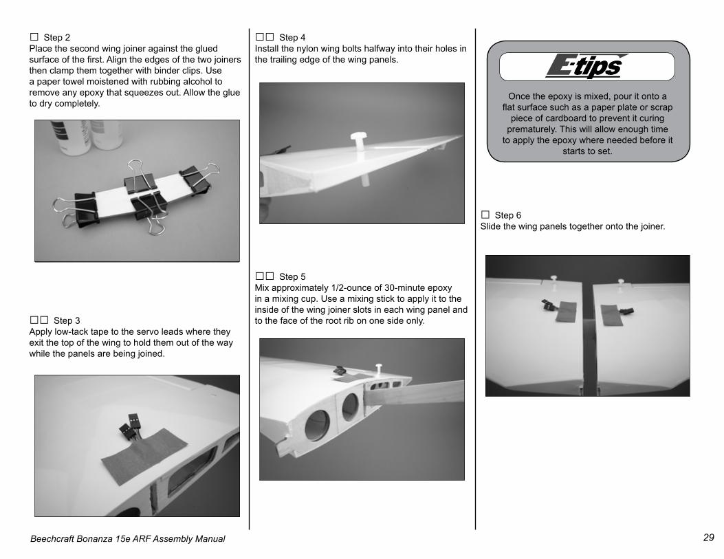
□□ Step 13Slide the silicone keeper on to the base of the clevis so that it will be accessible after the servo hatch is installed.
□□ Step 14Deflect the flap so that the horn on the leading edge is accessible. Insert the flap pushrod through the wing trailing edge with the bend facing outboard (towards the right hand wing tip) and connect the clevis to the flap horn.
Note: These instructions illustrate the right-hand flap servo installation. When performing this step for the left-hand flap, the pushrod will also have its bend facing towards the right-hand wing tip.
□□ Step 15Connect a 6-inch servo extension lead to the flapservo. Use dental floss to secure the connectors.
□□ Step 16Apply a small drop of thin CA to the flap servohatch mounting holes in the wing. Allow the CA tocure completely without using accelerator.
□□ Step 17There is a string provided in the wing to pull the servo leads through the wing. Tape the string to the aileron and flap servo extension leads and use it to draw the leads through the wing to the exit hole on top of the center section.
Use tape and a felt-tipped pen to label the aileron and flap servo leads where they
exit the wing.
28 Beechcraft Bonanza 15e ARF Assembly Manual
Note: Use your radio to center the flap servo before installing the servo hatch in the wing. The servo mounting location and pushrod length will position the flap with the trailing edge deflected 1/2-inch which is the mid-position. This measurement is made at the inboard end of the flap relative to the fixed portion of the wing trailing edge.
If using a 3-position switch to activate the flaps, center the arm on the servo with the switch in the middle position. If using a 2-position switch use a channel such as aileron or elevator to center the arm on the servo.
□□ Step 18Position the flap hatch over the opening and insert the pushrod in the inside hole of the servo arm. Secure the pushrod to the arm with a snap keeper.
□□ Step 19Use a #1 Phillips screwdriver to install the flap hatch to the wing with four #2 x 3/8-inch wood screws.
□ Step 20Repeat steps 1 through 19 to install the flap servo and pushrod in the opposite wing panel.
□ Step 1Mix a small amount of 30-minute epoxy and use a mixing stick to apply a thin layer to one face of a plywood wing joiner.
29Beechcraft Bonanza 15e ARF Assembly Manual
□ Step 2Place the second wing joiner against the glued surface of the first. Align the edges of the two joiners then clamp them together with binder clips. Use a paper towel moistened with rubbing alcohol to remove any epoxy that squeezes out. Allow the glue to dry completely.
□□ Step 3Apply low-tack tape to the servo leads where they exit the top of the wing to hold them out of the way while the panels are being joined.
□□ Step 4Install the nylon wing bolts halfway into their holes in the trailing edge of the wing panels.
□□ Step 5Mix approximately 1/2-ounce of 30-minute epoxy in a mixing cup. Use a mixing stick to apply it to the inside of the wing joiner slots in each wing panel and to the face of the root rib on one side only.
□ Step 6Slide the wing panels together onto the joiner.
Once the epoxy is mixed, pour it onto a flat surface such as a paper plate or scrap
piece of cardboard to prevent it curing prematurely. This will allow enough time
to apply the epoxy where needed before it starts to set.
30 Beechcraft Bonanza 15e ARF Assembly Manual
□ Step 7Check that the wing panels are aligned with each other and apply a binder clamp to the leading edge tabs to hold the wing halves together.
□ Step 8Stretch a rubber band between the left and right wing bolts on the upper and lower surfaces to hold the wing panels together.
□ Step 9Check that the wing panels are aligned to each other and that the panels are pushed together completely. Clean any excess epoxy off the wing with paper towels and rubbing alcohol. Stand the wing vertically while the epoxy cures so that the weight of the panels doesn’t cause the joint to spread and alter the dihedral angle.
□ Step 10Allow the glue to cure completely then remove the binder clamp, rubber bands and wing bolts.
Main Landing Gear InstallationParts Required Wing Landing gear #4 x 7/16-inch countersunk wood screws (8)
Tools Required Pencil #1 Phillips screwdriver Pin vise 5/64-inch drill bit Thin CA
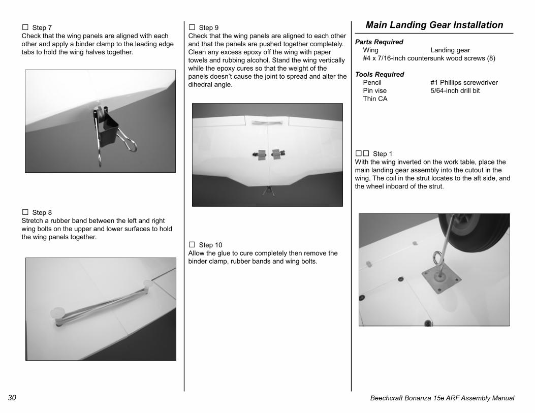
□□ Step 1With the wing inverted on the work table, place the main landing gear assembly into the cutout in the wing. The coil in the strut locates to the aft side, and the wheel inboard of the strut.
31Beechcraft Bonanza 15e ARF Assembly Manual
□□ Step 2Mark the mounting hole locations with a pencil.
□□ Step 3Use a 5/64-inch drill bit in a pin vise to drill the holes.
□□ Step 4Apply a drop of thin CA to each hole to strengthen the wood. Allow the CA to cure completely without using accelerator.
□□ Step 5Use a #1 Phillips screwdriver to install the landing gear with four #4 x 7/16-inch countersunk wood screws.
Optional Retract InstallationNose Gear
Parts Required Fuselage Retractable nose gear 2-inch nosewheel Adjustable axle #4 x 7/16-inch countersunk wood screws (4)
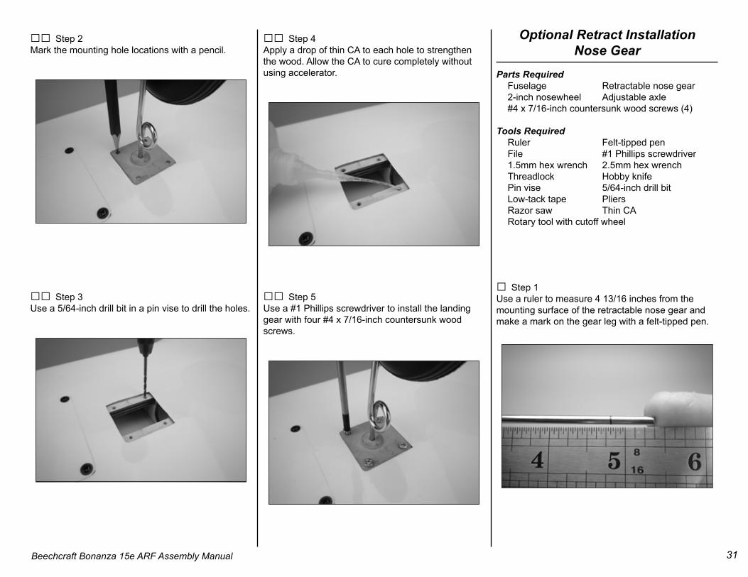
□ Step 1Use a ruler to measure 4 13/16 inches from the mounting surface of the retractable nose gear and make a mark on the gear leg with a felt-tipped pen.
32 Beechcraft Bonanza 15e ARF Assembly Manual
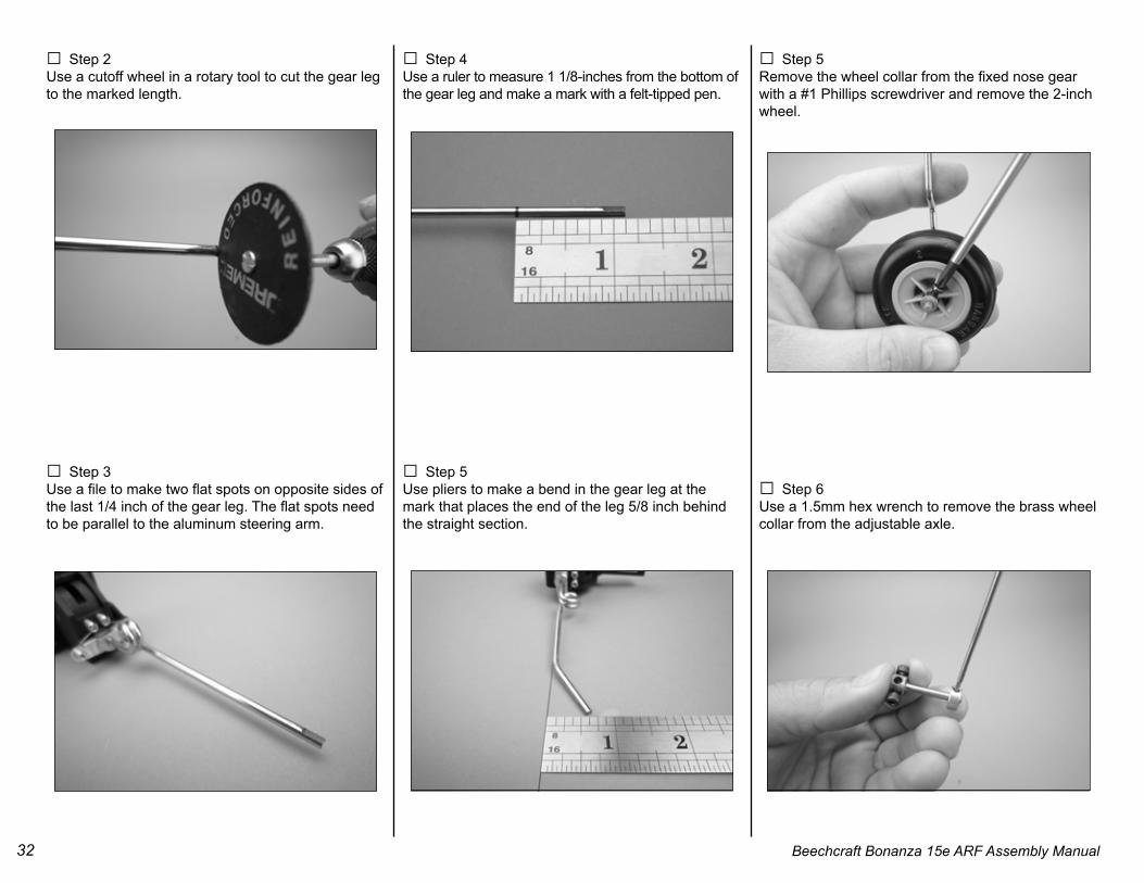
□ Step 2Use a cutoff wheel in a rotary tool to cut the gear leg to the marked length.
□ Step 3Use a file to make two flat spots on opposite sides of the last 1/4 inch of the gear leg. The flat spots need to be parallel to the aluminum steering arm.
□ Step 4Use a ruler to measure 1 1/8-inches from the bottom of the gear leg and make a mark with a felt-tipped pen.
□ Step 5Use pliers to make a bend in the gear leg at the mark that places the end of the leg 5/8 inch behind the straight section.
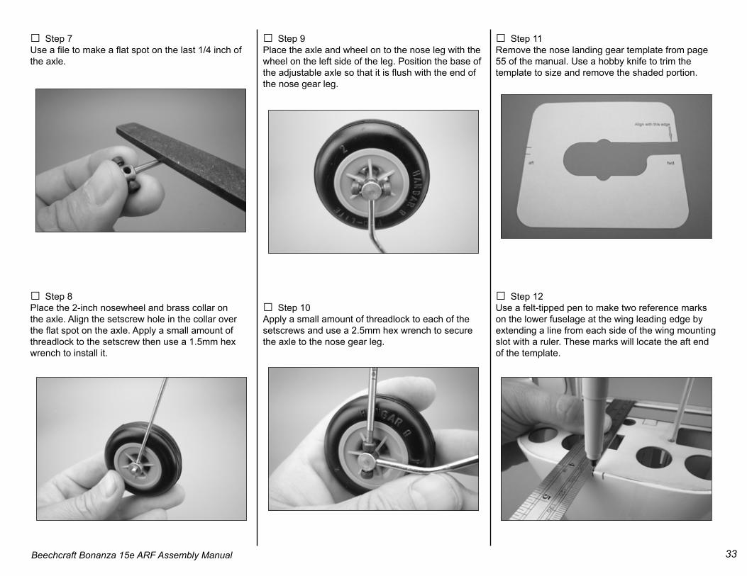
□ Step 5Remove the wheel collar from the fixed nose gear with a #1 Phillips screwdriver and remove the 2-inch wheel.
□ Step 6Use a 1.5mm hex wrench to remove the brass wheel collar from the adjustable axle.
33Beechcraft Bonanza 15e ARF Assembly Manual
□ Step 7Use a file to make a flat spot on the last 1/4 inch of the axle.
□ Step 8Place the 2-inch nosewheel and brass collar on the axle. Align the setscrew hole in the collar over the flat spot on the axle. Apply a small amount of threadlock to the setscrew then use a 1.5mm hex wrench to install it.
□ Step 9Place the axle and wheel on to the nose leg with the wheel on the left side of the leg. Position the base of the adjustable axle so that it is flush with the end of the nose gear leg.
□ Step 10Apply a small amount of threadlock to each of the setscrews and use a 2.5mm hex wrench to secure the axle to the nose gear leg.
□ Step 11Remove the nose landing gear template from page 55 of the manual. Use a hobby knife to trim the template to size and remove the shaded portion.
□ Step 12Use a felt-tipped pen to make two reference marks on the lower fuselage at the wing leading edge by extending a line from each side of the wing mounting slot with a ruler. These marks will locate the aft end of the template.
34 Beechcraft Bonanza 15e ARF Assembly Manual
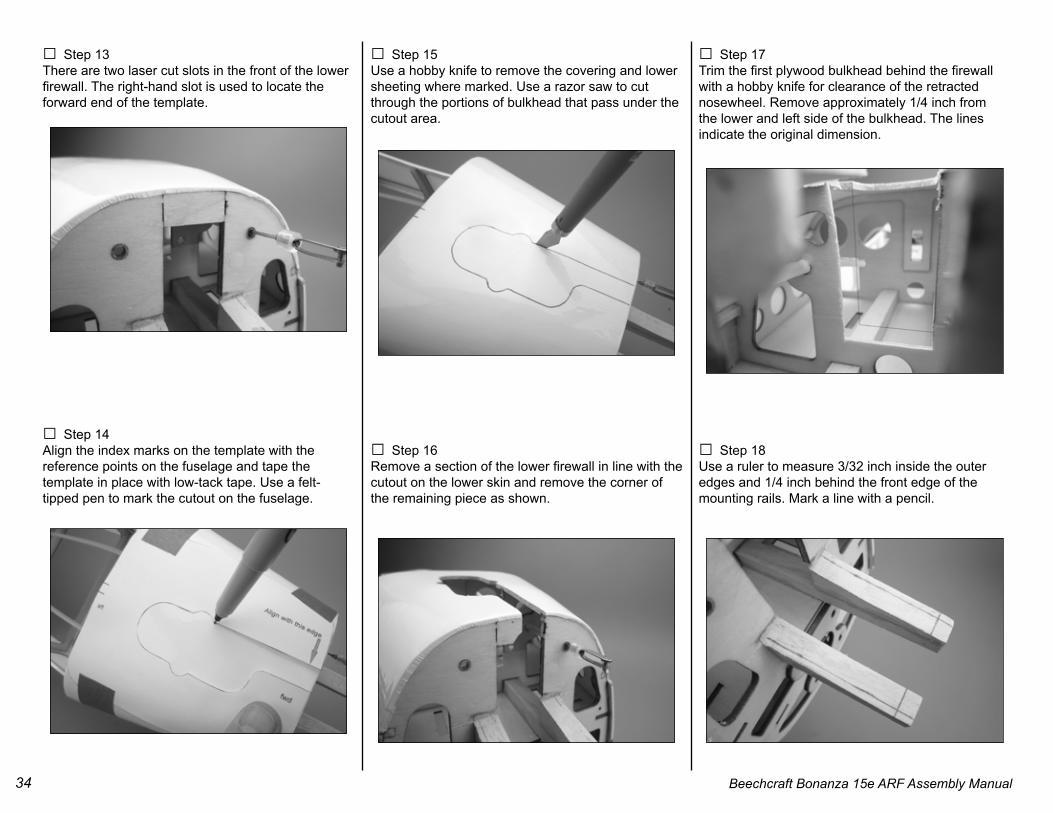
□ Step 13There are two laser cut slots in the front of the lower firewall. The right-hand slot is used to locate the forward end of the template.
□ Step 14Align the index marks on the template with the reference points on the fuselage and tape the template in place with low-tack tape. Use a felt-tipped pen to mark the cutout on the fuselage.
□ Step 15Use a hobby knife to remove the covering and lower sheeting where marked. Use a razor saw to cut through the portions of bulkhead that pass under the cutout area.
□ Step 16Remove a section of the lower firewall in line with the cutout on the lower skin and remove the corner of the remaining piece as shown.
□ Step 17Trim the first plywood bulkhead behind the firewall with a hobby knife for clearance of the retracted nosewheel. Remove approximately 1/4 inch from the lower and left side of the bulkhead. The lines indicate the original dimension.
□ Step 18Use a ruler to measure 3/32 inch inside the outer edges and 1/4 inch behind the front edge of the mounting rails. Mark a line with a pencil.
35Beechcraft Bonanza 15e ARF Assembly Manual
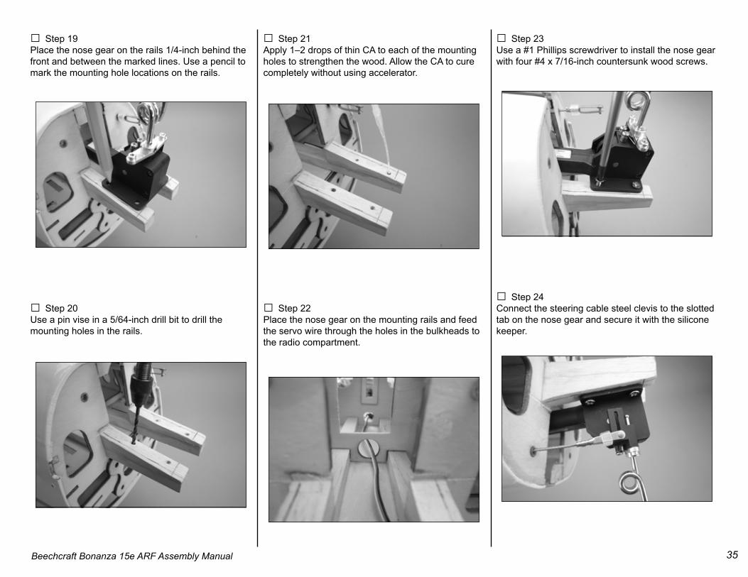
□ Step 19Place the nose gear on the rails 1/4-inch behind the front and between the marked lines. Use a pencil to mark the mounting hole locations on the rails.
□ Step 20Use a pin vise in a 5/64-inch drill bit to drill the mounting holes in the rails.
□ Step 21Apply 1–2 drops of thin CA to each of the mounting holes to strengthen the wood. Allow the CA to cure completely without using accelerator.
□ Step 22Place the nose gear on the mounting rails and feed the servo wire through the holes in the bulkheads to the radio compartment.
□ Step 23Use a #1 Phillips screwdriver to install the nose gear with four #4 x 7/16-inch countersunk wood screws.
□ Step 24Connect the steering cable steel clevis to the slotted tab on the nose gear and secure it with the silicone keeper.
36 Beechcraft Bonanza 15e ARF Assembly Manual
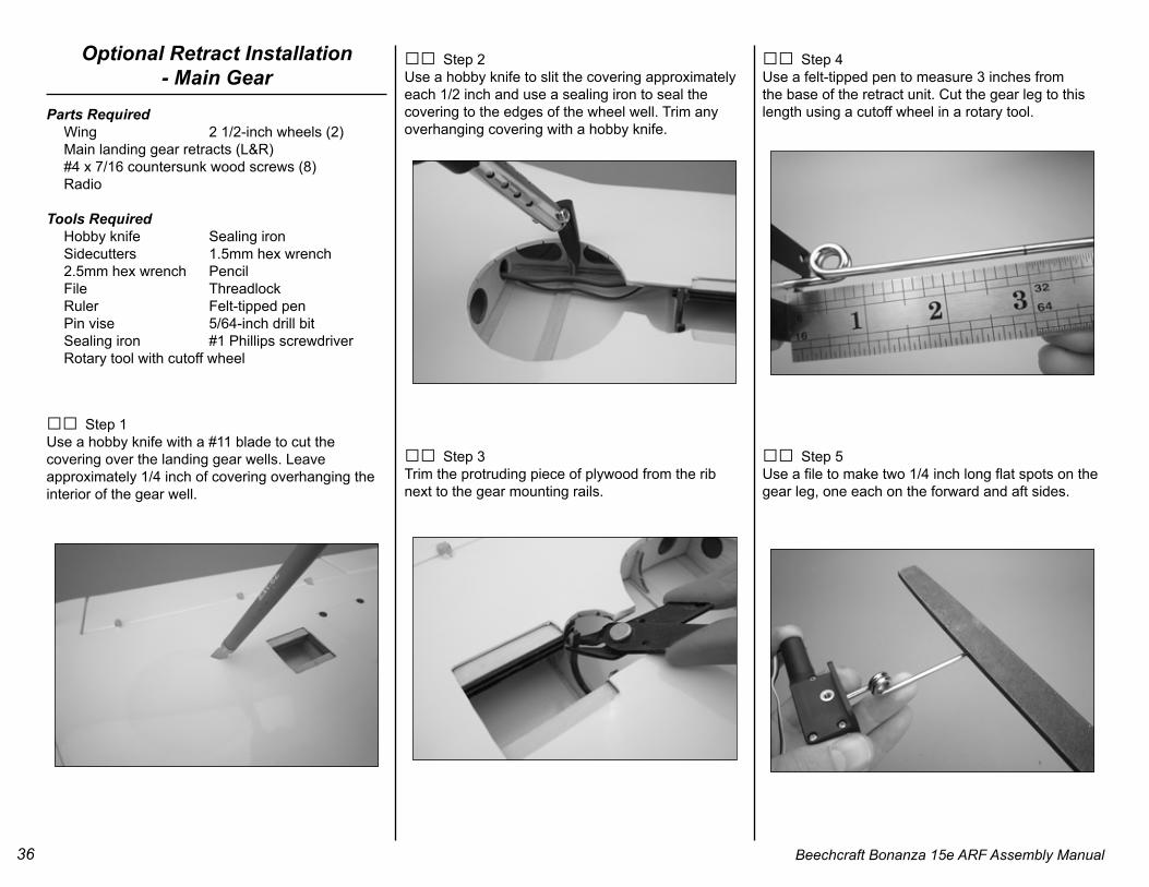
Optional Retract Installation- Main Gear
Parts Required Wing 2 1/2-inch wheels (2) Main landing gear retracts (L&R) #4 x 7/16 countersunk wood screws (8) Radio
Tools Required Hobby knife Sealing iron Sidecutters 1.5mm hex wrench 2.5mm hex wrench Pencil File Threadlock Ruler Felt-tipped pen Pin vise 5/64-inch drill bit Sealing iron #1 Phillips screwdriver Rotary tool with cutoff wheel
□□ Step 1Use a hobby knife with a #11 blade to cut the covering over the landing gear wells. Leave approximately 1/4 inch of covering overhanging the interior of the gear well.
□□ Step 2Use a hobby knife to slit the covering approximately each 1/2 inch and use a sealing iron to seal the covering to the edges of the wheel well. Trim any overhanging covering with a hobby knife.
□□ Step 3Trim the protruding piece of plywood from the rib next to the gear mounting rails.
□□ Step 4Use a felt-tipped pen to measure 3 inches from the base of the retract unit. Cut the gear leg to this length using a cutoff wheel in a rotary tool.
□□ Step 5Use a file to make two 1/4 inch long flat spots on the gear leg, one each on the forward and aft sides.
37Beechcraft Bonanza 15e ARF Assembly Manual
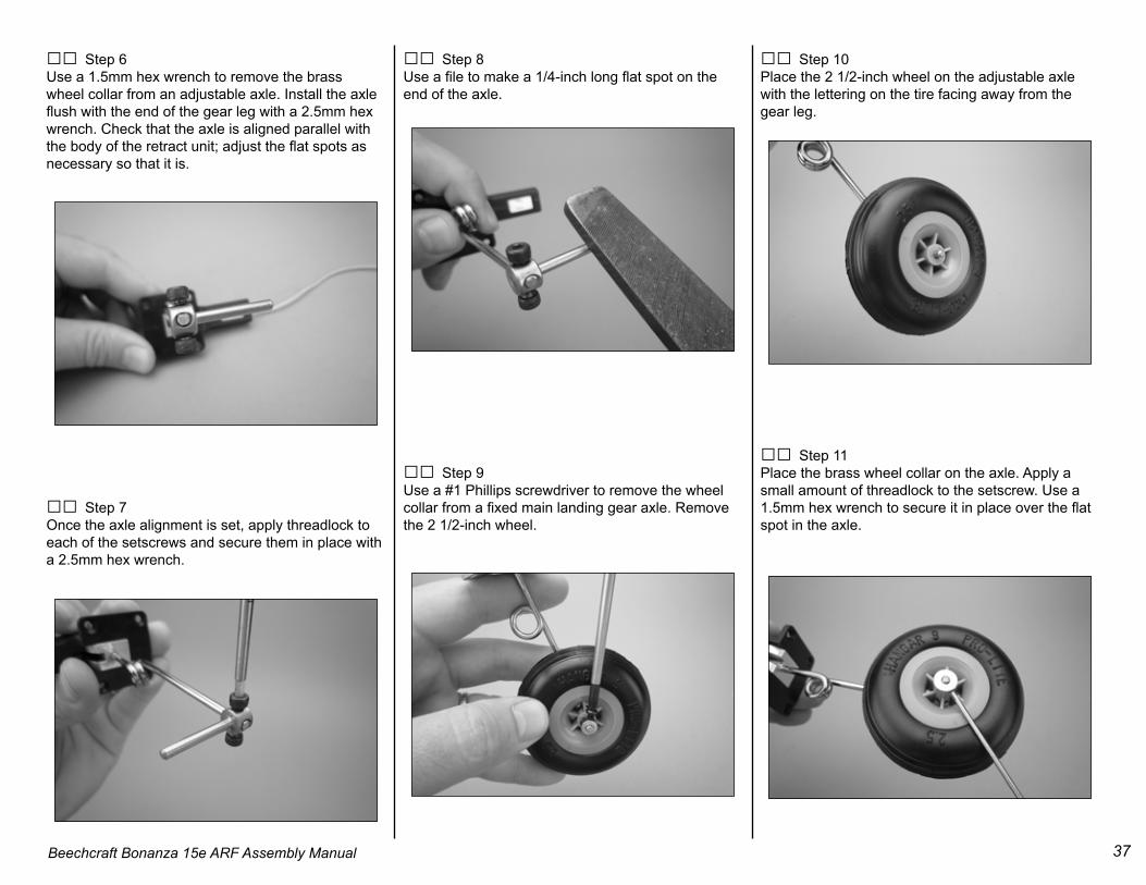
□□ Step 6Use a 1.5mm hex wrench to remove the brass wheel collar from an adjustable axle. Install the axle flush with the end of the gear leg with a 2.5mm hex wrench. Check that the axle is aligned parallel with the body of the retract unit; adjust the flat spots as necessary so that it is.
□□ Step 7Once the axle alignment is set, apply threadlock to each of the setscrews and secure them in place with a 2.5mm hex wrench.
□□ Step 8Use a file to make a 1/4-inch long flat spot on the end of the axle.
□□ Step 9Use a #1 Phillips screwdriver to remove the wheel collar from a fixed main landing gear axle. Remove the 2 1/2-inch wheel.
□□ Step 10Place the 2 1/2-inch wheel on the adjustable axle with the lettering on the tire facing away from the gear leg.
□□ Step 11Place the brass wheel collar on the axle. Apply a small amount of threadlock to the setscrew. Use a 1.5mm hex wrench to secure it in place over the flat spot in the axle.
38 Beechcraft Bonanza 15e ARF Assembly Manual
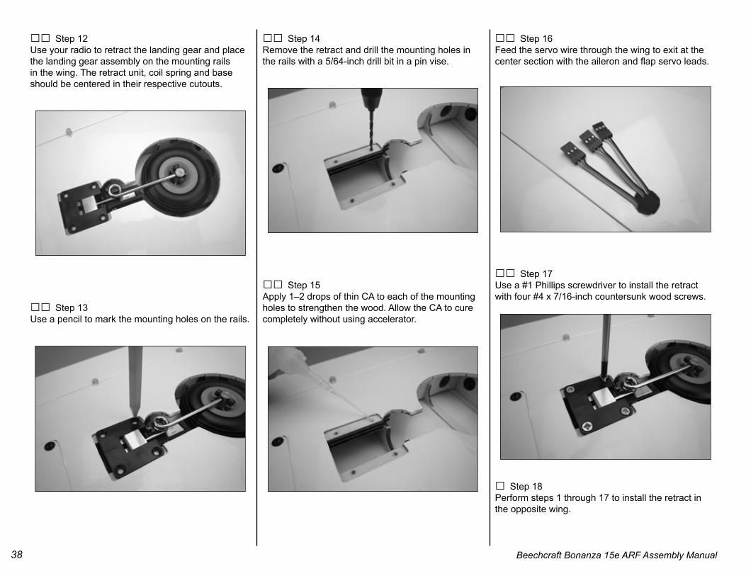
□□ Step 12Use your radio to retract the landing gear and place the landing gear assembly on the mounting rails in the wing. The retract unit, coil spring and base should be centered in their respective cutouts.
□□ Step 13Use a pencil to mark the mounting holes on the rails.
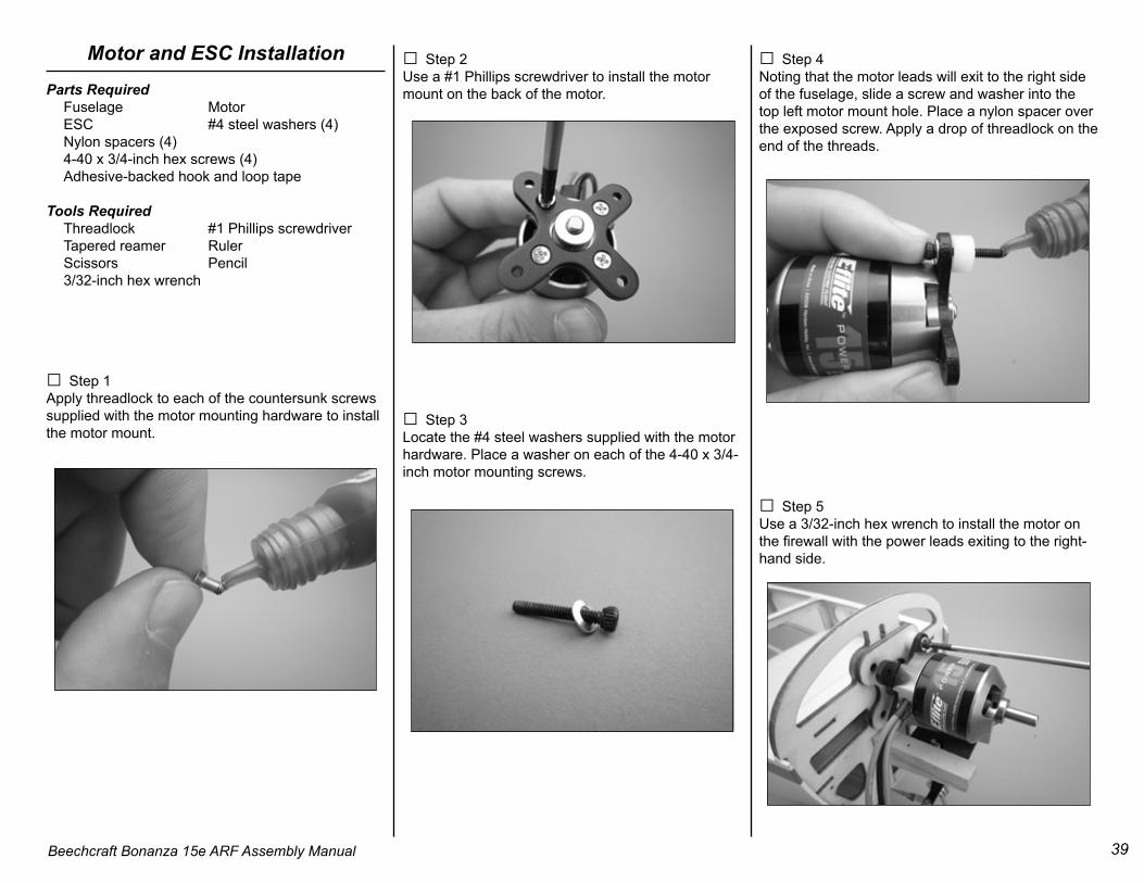
□□ Step 14Remove the retract and drill the mounting holes in the rails with a 5/64-inch drill bit in a pin vise.
□□ Step 15Apply 1–2 drops of thin CA to each of the mounting holes to strengthen the wood. Allow the CA to cure completely without using accelerator.
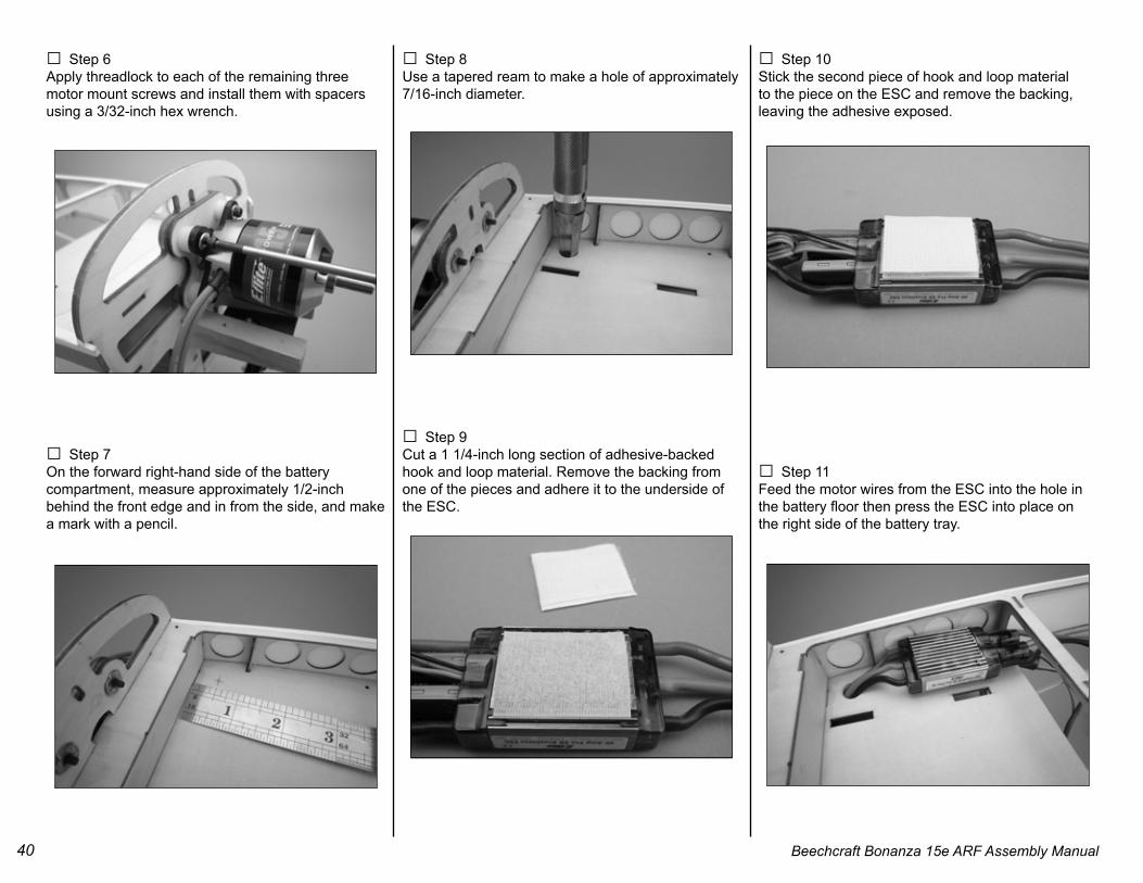
□□ Step 16Feed the servo wire through the wing to exit at the center section with the aileron and flap servo leads.
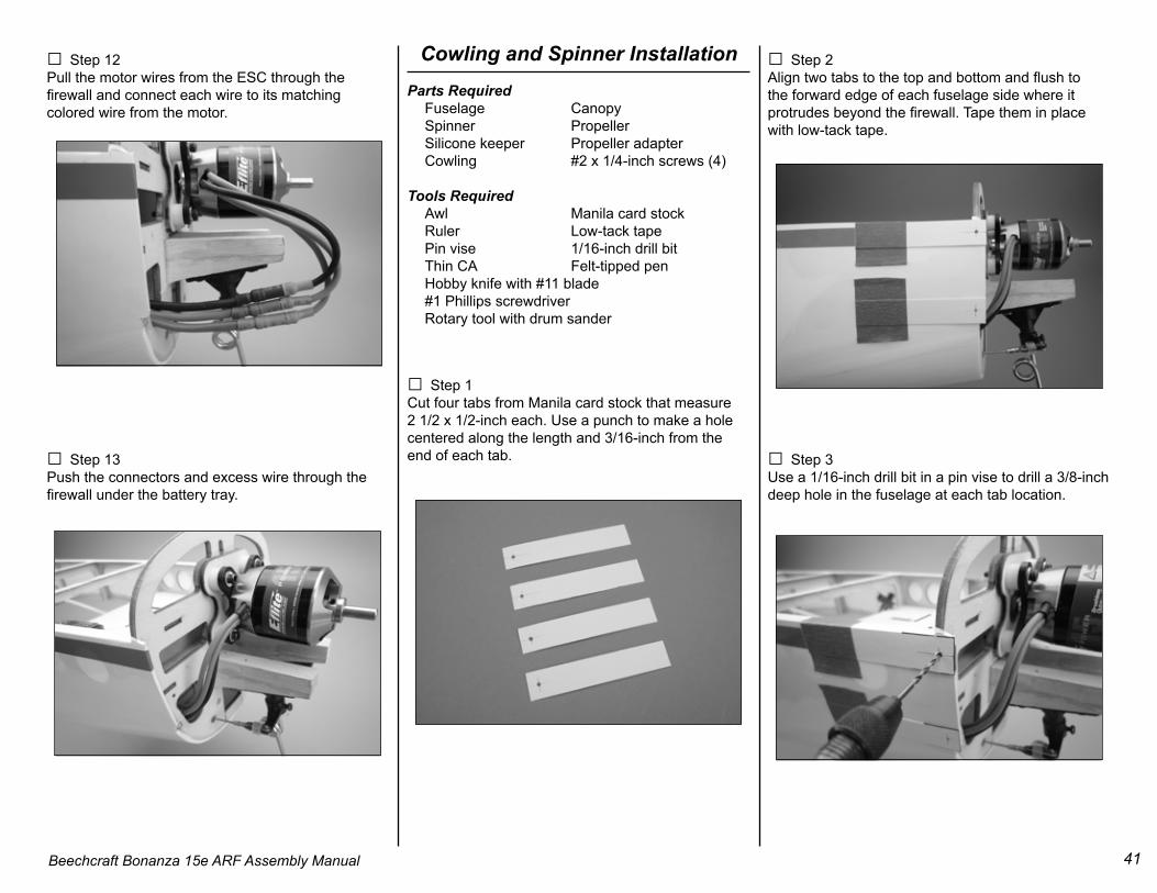
□□ Step 17Use a #1 Phillips screwdriver to install the retract with four #4 x 7/16-inch countersunk wood screws.
□ Step 18Perform steps 1 through 17 to install the retract in the opposite wing.
39Beechcraft Bonanza 15e ARF Assembly Manual
Motor and ESC InstallationParts Required Fuselage Motor ESC #4 steel washers (4) Nylon spacers (4) 4-40 x 3/4-inch hex screws (4) Adhesive-backed hook and loop tape
□ Step 1Apply threadlock to each of the countersunk screws supplied with the motor mounting hardware to install the motor mount.
□ Step 2Use a #1 Phillips screwdriver to install the motor mount on the back of the motor.
□ Step 3Locate the #4 steel washers supplied with the motor hardware. Place a washer on each of the 4-40 x 3/4-inch motor mounting screws.
□ Step 4Noting that the motor leads will exit to the right side of the fuselage, slide a screw and washer into the top left motor mount hole. Place a nylon spacer over the exposed screw. Apply a drop of threadlock on the end of the threads.
□ Step 5Use a 3/32-inch hex wrench to install the motor on the firewall with the power leads exiting to the right- hand side.
40 Beechcraft Bonanza 15e ARF Assembly Manual
□ Step 6Apply threadlock to each of the remaining three motor mount screws and install them with spacers using a 3/32-inch hex wrench.
□ Step 7On the forward right-hand side of the battery compartment, measure approximately 1/2-inch behind the front edge and in from the side, and make a mark with a pencil.
□ Step 8Use a tapered ream to make a hole of approximately 7/16-inch diameter.
□ Step 9Cut a 1 1/4-inch long section of adhesive-backed hook and loop material. Remove the backing from one of the pieces and adhere it to the underside of the ESC.
□ Step 10Stick the second piece of hook and loop material to the piece on the ESC and remove the backing, leaving the adhesive exposed.
□ Step 11Feed the motor wires from the ESC into the hole in the battery floor then press the ESC into place on the right side of the battery tray.
41Beechcraft Bonanza 15e ARF Assembly Manual
□ Step 12Pull the motor wires from the ESC through the firewall and connect each wire to its matching colored wire from the motor.
□ Step 13Push the connectors and excess wire through the firewall under the battery tray.
Cowling and Spinner InstallationParts Required Fuselage Canopy Spinner Propeller Silicone keeper Propeller adapter Cowling #2 x 1/4-inch screws (4) Tools Required Awl Manila card stock Ruler Low-tack tape Pin vise 1/16-inch drill bit Thin CA Felt-tipped pen Hobby knife with #11 blade #1 Phillips screwdriver Rotary tool with drum sander
□ Step 1Cut four tabs from Manila card stock that measure 2 1/2 x 1/2-inch each. Use a punch to make a hole centered along the length and 3/16-inch from the end of each tab.
□ Step 2Align two tabs to the top and bottom and flush to the forward edge of each fuselage side where it protrudes beyond the firewall. Tape them in place with low-tack tape.
□ Step 3Use a 1/16-inch drill bit in a pin vise to drill a 3/8-inch deep hole in the fuselage at each tab location.
42 Beechcraft Bonanza 15e ARF Assembly Manual
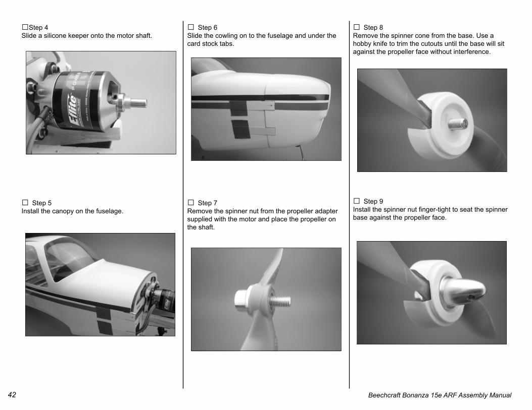
□Step 4Slide a silicone keeper onto the motor shaft.
□ Step 5Install the canopy on the fuselage.
□ Step 6Slide the cowling on to the fuselage and under the card stock tabs.
□ Step 7Remove the spinner nut from the propeller adapter supplied with the motor and place the propeller on the shaft.
□ Step 8Remove the spinner cone from the base. Use a hobby knife to trim the cutouts until the base will sit against the propeller face without interference.
□ Step 9Install the spinner nut finger-tight to seat the spinner base against the propeller face.
43Beechcraft Bonanza 15e ARF Assembly Manual
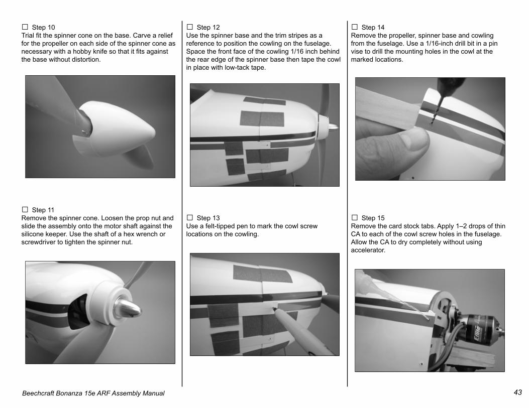
□ Step 10Trial fit the spinner cone on the base. Carve a relief for the propeller on each side of the spinner cone as necessary with a hobby knife so that it fits against the base without distortion.
□ Step 11Remove the spinner cone. Loosen the prop nut and slide the assembly onto the motor shaft against the silicone keeper. Use the shaft of a hex wrench or screwdriver to tighten the spinner nut.
□ Step 12Use the spinner base and the trim stripes as a reference to position the cowling on the fuselage. Space the front face of the cowling 1/16 inch behind the rear edge of the spinner base then tape the cowl in place with low-tack tape.
□ Step 13Use a felt-tipped pen to mark the cowl screw locations on the cowling.
□ Step 14Remove the propeller, spinner base and cowling from the fuselage. Use a 1/16-inch drill bit in a pin vise to drill the mounting holes in the cowl at the marked locations.
□ Step 15Remove the card stock tabs. Apply 1–2 drops of thin CA to each of the cowl screw holes in the fuselage. Allow the CA to dry completely without using accelerator.
44 Beechcraft Bonanza 15e ARF Assembly Manual
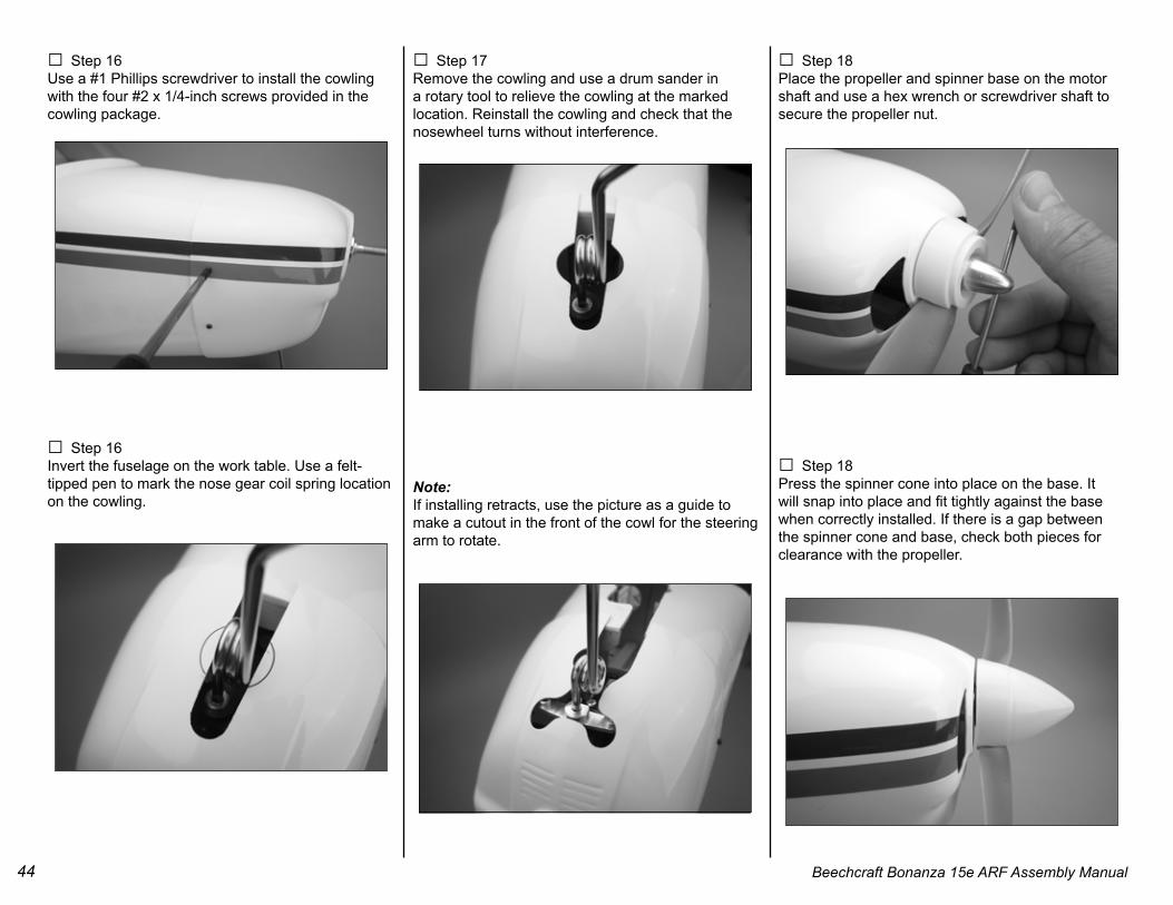
□ Step 16Use a #1 Phillips screwdriver to install the cowling with the four #2 x 1/4-inch screws provided in the cowling package.
□ Step 16Invert the fuselage on the work table. Use a felt-tipped pen to mark the nose gear coil spring location on the cowling.
□ Step 17Remove the cowling and use a drum sander in a rotary tool to relieve the cowling at the marked location. Reinstall the cowling and check that the nosewheel turns without interference.
Note:If installing retracts, use the picture as a guide to make a cutout in the front of the cowl for the steering arm to rotate.
□ Step 18Place the propeller and spinner base on the motor shaft and use a hex wrench or screwdriver shaft to secure the propeller nut.
□ Step 18Press the spinner cone into place on the base. It will snap into place and fit tightly against the base when correctly installed. If there is a gap between the spinner cone and base, check both pieces for clearance with the propeller.
45Beechcraft Bonanza 15e ARF Assembly Manual
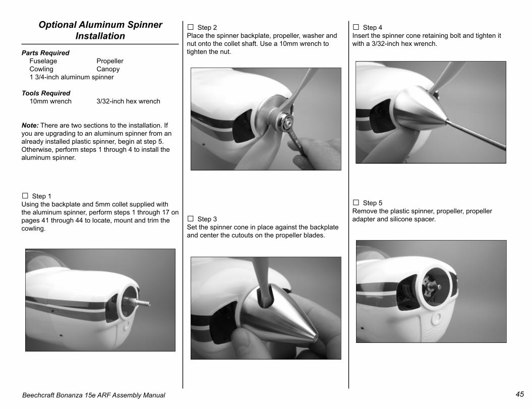
Optional Aluminum Spinner Installation
Parts Required Fuselage Propeller Cowling Canopy 1 3/4-inch aluminum spinner
Tools Required 10mm wrench 3/32-inch hex wrench
Note: There are two sections to the installation. If you are upgrading to an aluminum spinner from an already installed plastic spinner, begin at step 5. Otherwise, perform steps 1 through 4 to install the aluminum spinner.
□ Step 1Using the backplate and 5mm collet supplied with the aluminum spinner, perform steps 1 through 17 on pages 41 through 44 to locate, mount and trim the cowling.
□ Step 2Place the spinner backplate, propeller, washer and nut onto the collet shaft. Use a 10mm wrench to tighten the nut.
□ Step 3Set the spinner cone in place against the backplate and center the cutouts on the propeller blades.
□ Step 4Insert the spinner cone retaining bolt and tighten it with a 3/32-inch hex wrench.
□ Step 5Remove the plastic spinner, propeller, propeller adapter and silicone spacer.
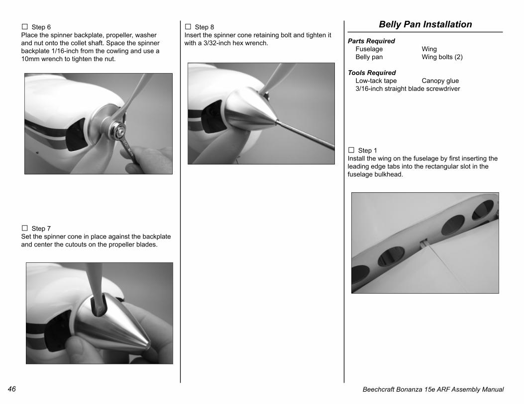
46 Beechcraft Bonanza 15e ARF Assembly Manual
□ Step 6Place the spinner backplate, propeller, washer and nut onto the collet shaft. Space the spinner backplate 1/16-inch from the cowling and use a 10mm wrench to tighten the nut.
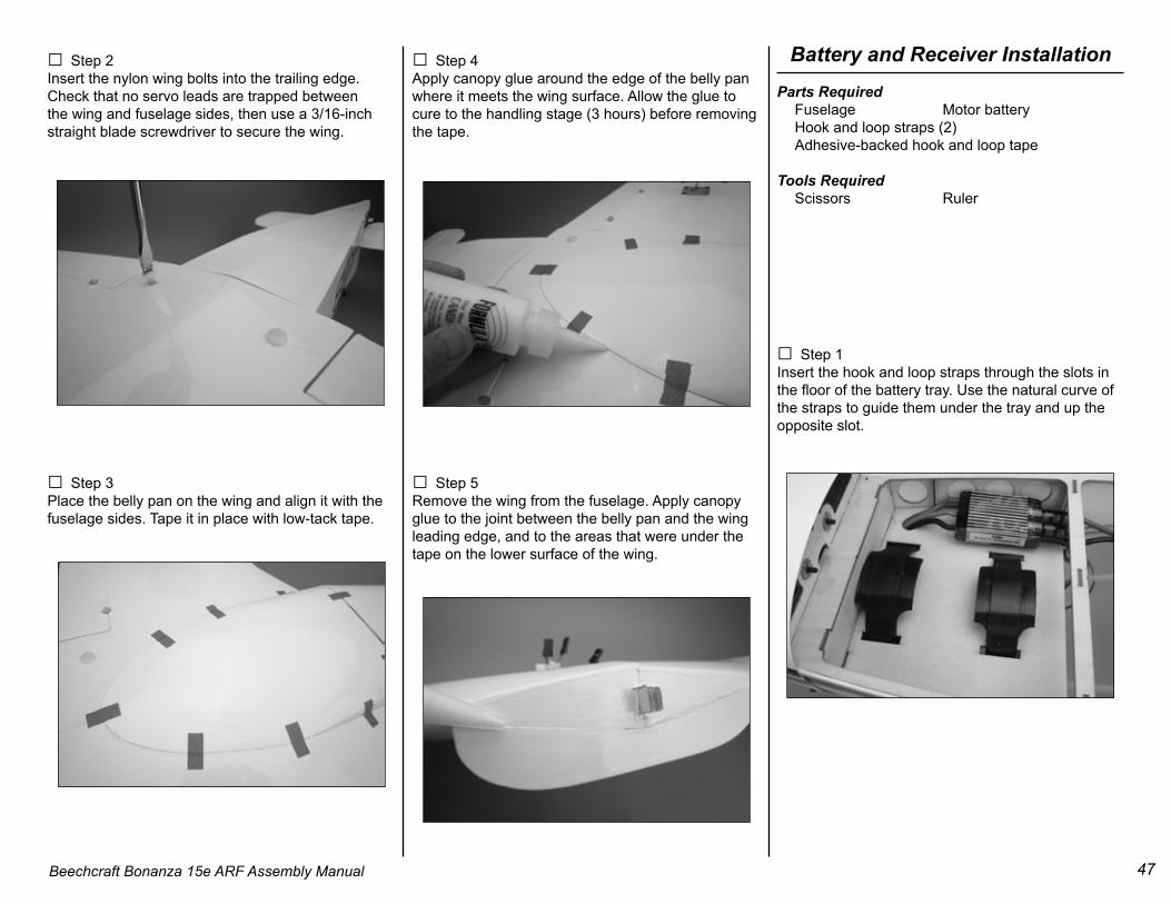
□ Step 7Set the spinner cone in place against the backplate and center the cutouts on the propeller blades.
□ Step 8Insert the spinner cone retaining bolt and tighten it with a 3/32-inch hex wrench.
Belly Pan InstallationParts Required Fuselage Wing Belly pan Wing bolts (2)
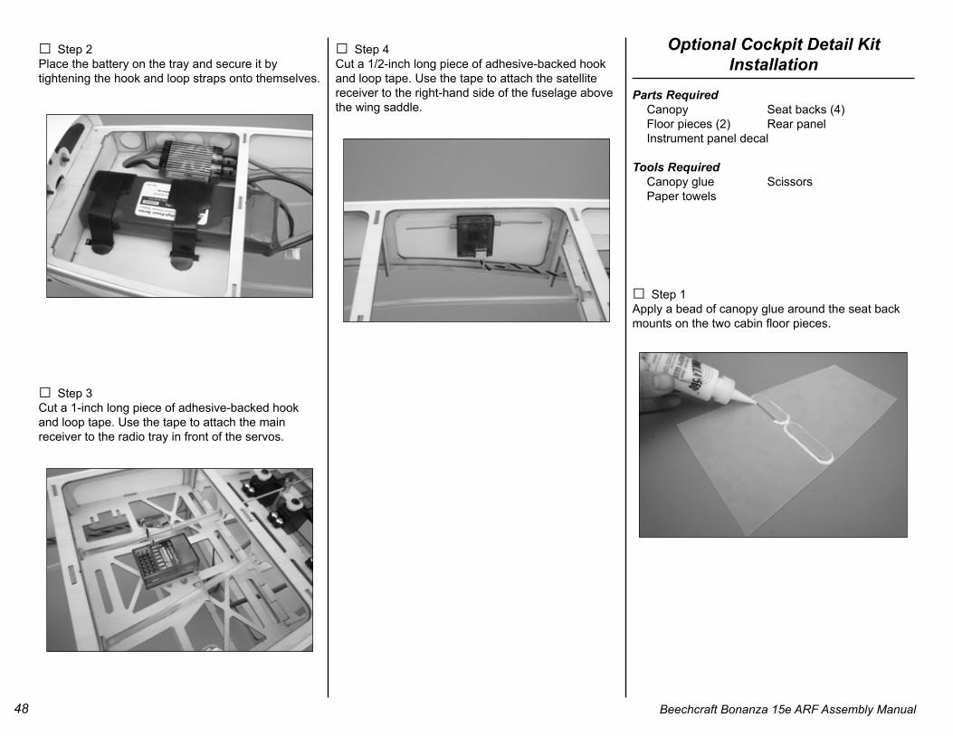
□ Step 1Install the wing on the fuselage by first inserting the leading edge tabs into the rectangular slot in the fuselage bulkhead.
47Beechcraft Bonanza 15e ARF Assembly Manual
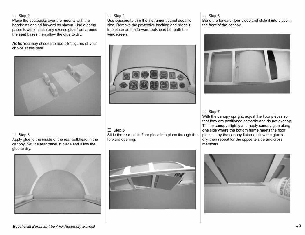
□ Step 2Insert the nylon wing bolts into the trailing edge. Check that no servo leads are trapped between the wing and fuselage sides, then use a 3/16-inch straight blade screwdriver to secure the wing.
□ Step 3Place the belly pan on the wing and align it with the fuselage sides. Tape it in place with low-tack tape.
□ Step 4Apply canopy glue around the edge of the belly pan where it meets the wing surface. Allow the glue to cure to the handling stage (3 hours) before removing the tape.
□ Step 5Remove the wing from the fuselage. Apply canopy glue to the joint between the belly pan and the wing leading edge, and to the areas that were under the tape on the lower surface of the wing.
Battery and Receiver InstallationParts Required Fuselage Motor battery Hook and loop straps (2) Adhesive-backed hook and loop tape
Tools Required Scissors Ruler
□ Step 1Insert the hook and loop straps through the slots in the floor of the battery tray. Use the natural curve of the straps to guide them under the tray and up the opposite slot.
48 Beechcraft Bonanza 15e ARF Assembly Manual
□ Step 2Place the battery on the tray and secure it by tightening the hook and loop straps onto themselves.
□ Step 3Cut a 1-inch long piece of adhesive-backed hook and loop tape. Use the tape to attach the main receiver to the radio tray in front of the servos.
□ Step 4Cut a 1/2-inch long piece of adhesive-backed hook and loop tape. Use the tape to attach the satellite receiver to the right-hand side of the fuselage above the wing saddle.
□ Step 1Apply a bead of canopy glue around the seat back mounts on the two cabin floor pieces.
49Beechcraft Bonanza 15e ARF Assembly Manual
□ Step 2Place the seatbacks over the mounts with the headrests angled forward as shown. Use a damp paper towel to clean any excess glue from around the seat bases then allow the glue to dry.
Note: You may choose to add pilot figures of your choice at this time.
□ Step 3Apply glue to the inside of the rear bulkhead in the canopy. Set the rear panel in place and allow the glue to dry.
□ Step 4Use scissors to trim the instrument panel decal to size. Remove the protective backing and press it into place on the forward bulkhead beneath the windscreen.
□ Step 5Slide the rear cabin floor piece into place through the forward opening.
□ Step 6Bend the forward floor piece and slide it into place in the front of the canopy.
□ Step 7With the canopy upright, adjust the floor pieces so that they are positioned correctly and do not overlap. Tilt the canopy slightly and apply canopy glue along one side where the bottom frame meets the floor pieces. Lay the canopy flat and allow the glue to dry, then repeat for the opposite side and cross members.
50 Beechcraft Bonanza 15e ARF Assembly Manual
Final AssemblyParts Required Fuselage Wing Wing bolts (2) 3-inch Y-harnesses (3) Radio 9-inch servo extension 2mm x 5mm machine screw
□ Step 1Use a 3/16-inch straight blade screwdriver to install the wing on the fuselage. Make sure that no servo leads are trapped between the wing and fuselage.
□ Step 2 Connect a 3-inch Y-harness to the rudder and nosewheel steering servos.
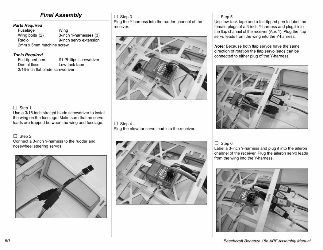
□ Step 3Plug the Y-harness into the rudder channel of the receiver.
□ Step 4Plug the elevator servo lead into the receiver.
□ Step 5Use low-tack tape and a felt-tipped pen to label the female plugs of a 3-inch Y-harness and plug it into the flap channel of the receiver (Aux 1). Plug the flap servo leads from the wing into the Y-harness.
Note: Because both flap servos have the same direction of rotation the flap servo leads can be connected to either plug of the Y-harness.
□ Step 6Label a 3-inch Y-harness and plug it into the aileron channel of the receiver. Plug the aileron servo leads from the wing into the Y-harness.
51Beechcraft Bonanza 15e ARF Assembly Manual
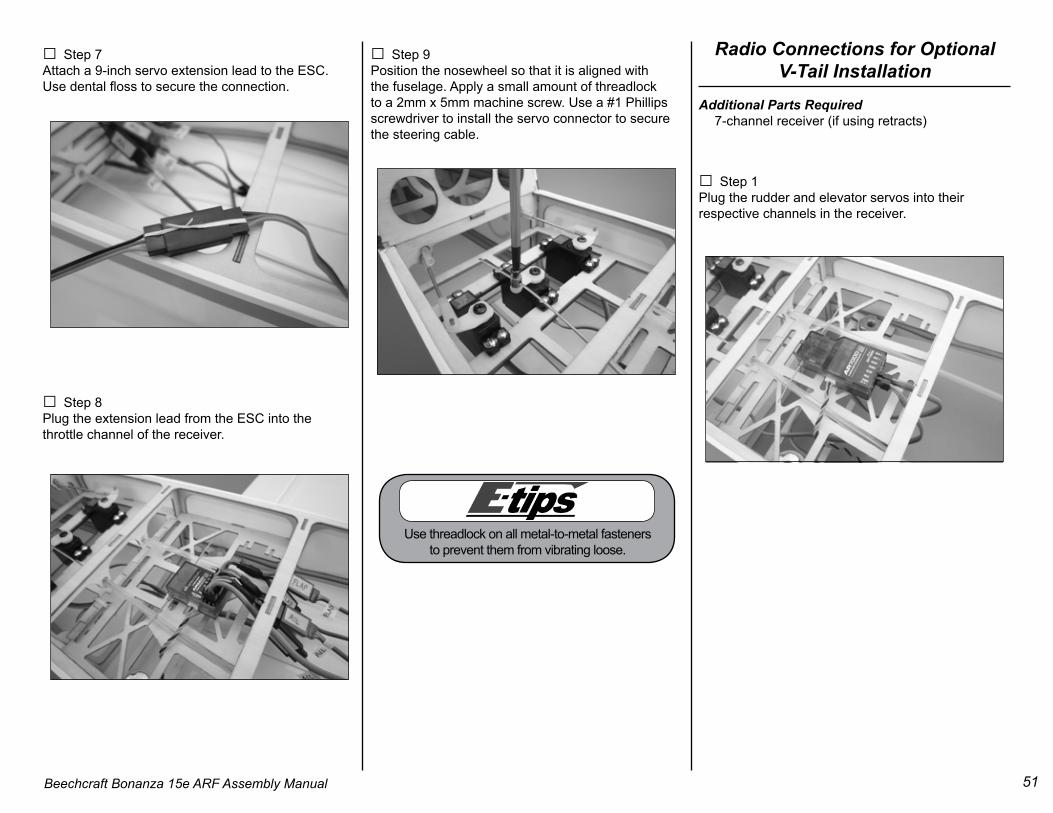
□ Step 7Attach a 9-inch servo extension lead to the ESC. Use dental floss to secure the connection.
□ Step 8Plug the extension lead from the ESC into the throttle channel of the receiver.
□ Step 9Position the nosewheel so that it is aligned with the fuselage. Apply a small amount of threadlock to a 2mm x 5mm machine screw. Use a #1 Phillips screwdriver to install the servo connector to secure the steering cable.
Radio Connections for Optional V-Tail Installation
Additional Parts Required 7-channel receiver (if using retracts)
□ Step 1Plug the rudder and elevator servos into their respective channels in the receiver.
Use threadlock on all metal-to-metal fasteners to prevent them from vibrating loose.
52 Beechcraft Bonanza 15e ARF Assembly Manual
□ Step 2Plug the nosewheel steering servo into an auxiliary channel. Because of the interaction between rudder and elevator servos during V-tail operation, the rudder and nosewheel steering servos cannot be connected with a Y-harness.
□ Step 3Perform steps 4 through 8 on pages 50 and 51 to make the remainder of the connections.
□ Step 4When setting up the model it will be necessary to enable the V-tail mixing function, and also create a mix to operate the nosewheel steering. The rudder channel will be the master, and the nosewheel steering the slave channel. Refer to the instructions provided with your radio to set up the mix.
Radio Connections for Retracts
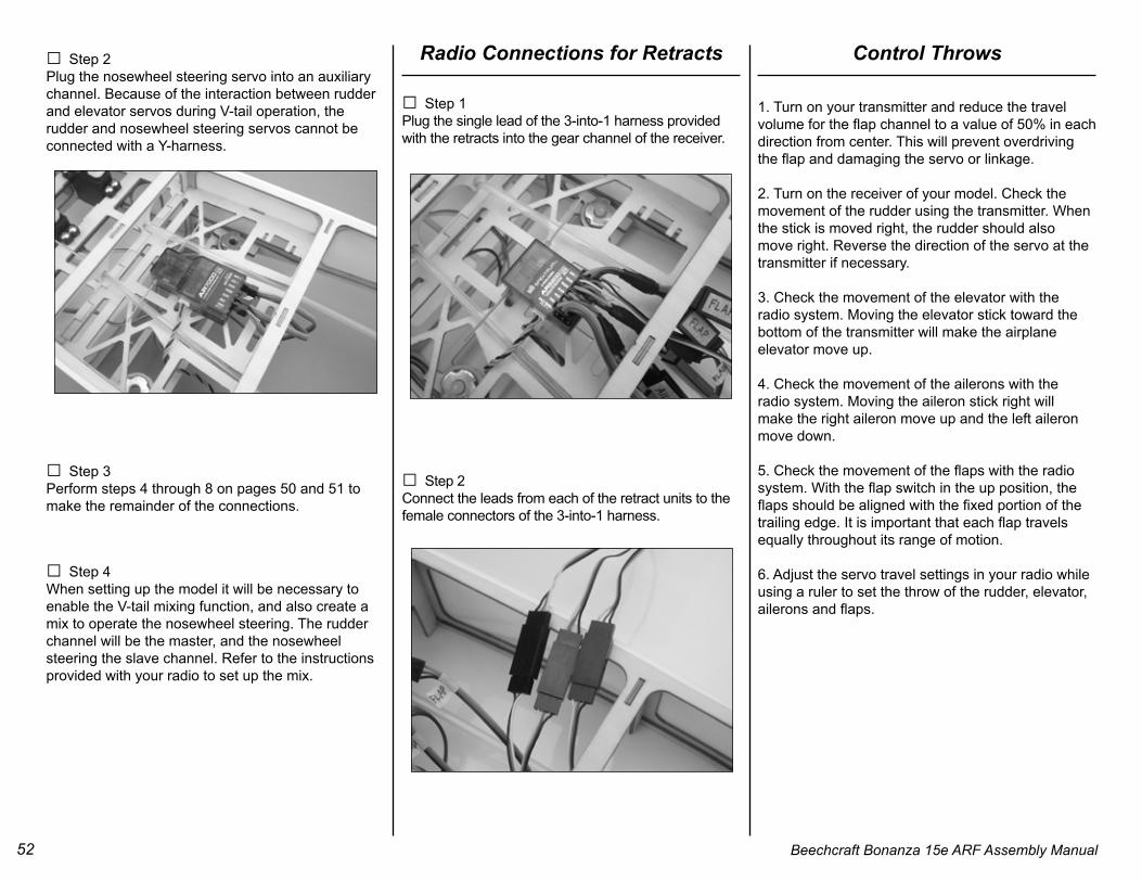
□ Step 1Plug the single lead of the 3-into-1 harness provided with the retracts into the gear channel of the receiver.
□ Step 2Connect the leads from each of the retract units to the female connectors of the 3-into-1 harness.
Control Throws
1. Turn on your transmitter and reduce the travel volume for the flap channel to a value of 50% in each direction from center. This will prevent overdriving the flap and damaging the servo or linkage.
2. Turn on the receiver of your model. Check the movement of the rudder using the transmitter. When the stick is moved right, the rudder should also move right. Reverse the direction of the servo at the transmitter if necessary.
3. Check the movement of the elevator with theradio system. Moving the elevator stick toward thebottom of the transmitter will make the airplaneelevator move up.
4. Check the movement of the ailerons with theradio system. Moving the aileron stick right willmake the right aileron move up and the left aileronmove down.
5. Check the movement of the flaps with the radio system. With the flap switch in the up position, the flaps should be aligned with the fixed portion of the trailing edge. It is important that each flap travels equally throughout its range of motion.
6. Adjust the servo travel settings in your radio while using a ruler to set the throw of the rudder, elevator, ailerons and flaps.
53Beechcraft Bonanza 15e ARF Assembly Manual
Aileron High Rate Up 3/8-inch (10mm) Down 3/8-inch (10mm)
Aileron Low Rate Up 1/4-inch (6mm) Down 1/4-inch (6mm)
Elevator High Rate Up 1/2-inch (13mm) Down 1/2-inch (13mm)
Elevator Low Rate Up 3/8-inch (10mm) Down 3/8-inch (10mm)
Rudder High Rate Left 1 1/4-inch (32mm) Right 1 1/4-inch (32mm)
Rudder Low Rate Left 1-inch (25mm) Right 1-inch (25mm)
Flap Travel Up Align with wing trailing edge Center 1/2-inch down (13mm) Down 1 1/4-inch down (32mm)
Center of GravityAn important part of preparing the aircraft for flight isproperly balancing the model.
Caution: Do not inadvertently skip this step!
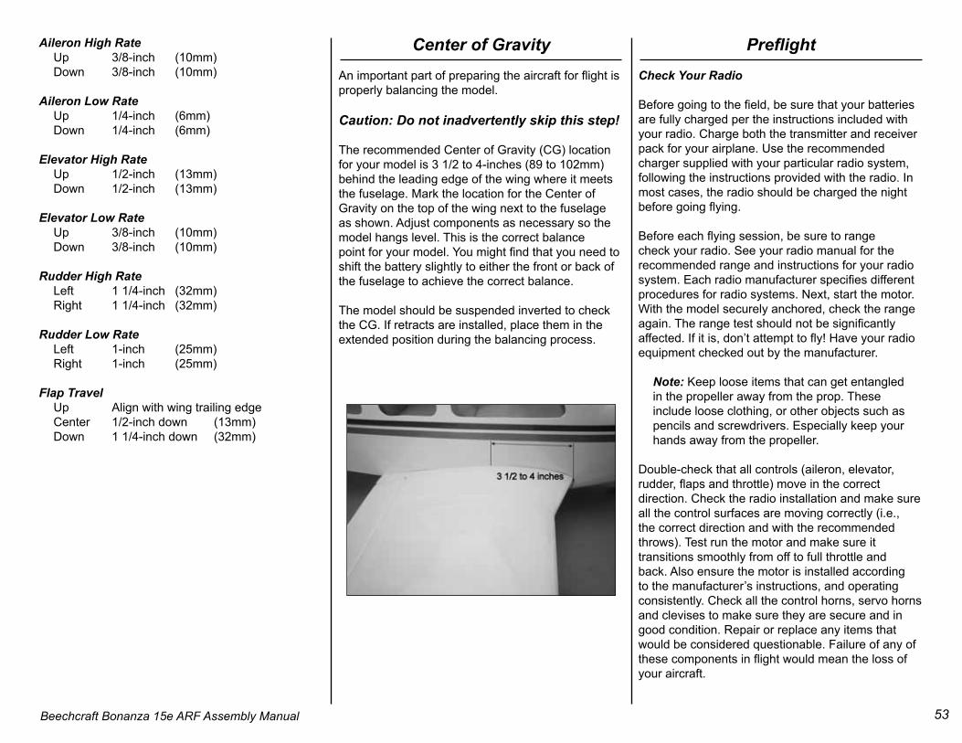
The recommended Center of Gravity (CG) locationfor your model is 3 1/2 to 4-inches (89 to 102mm) behind the leading edge of the wing where it meets the fuselage. Mark the location for the Center of Gravity on the top of the wing next to the fuselage as shown. Adjust components as necessary so the model hangs level. This is the correct balancepoint for your model. You might find that you need toshift the battery slightly to either the front or back ofthe fuselage to achieve the correct balance.
The model should be suspended inverted to check the CG. If retracts are installed, place them in the extended position during the balancing process.
PreflightCheck Your Radio
Before going to the field, be sure that your batteriesare fully charged per the instructions included withyour radio. Charge both the transmitter and receiverpack for your airplane. Use the recommended charger supplied with your particular radio system, following the instructions provided with the radio. In most cases, the radio should be charged the night before going flying.
Before each flying session, be sure to range check your radio. See your radio manual for the recommended range and instructions for your radio system. Each radio manufacturer specifies different procedures for radio systems. Next, start the motor. With the model securely anchored, check the range again. The range test should not be significantly affected. If it is, don’t attempt to fly! Have your radio equipment checked out by the manufacturer.
Note: Keep loose items that can get entangled in the propeller away from the prop. These include loose clothing, or other objects such as pencils and screwdrivers. Especially keep your hands away from the propeller.
Double-check that all controls (aileron, elevator, rudder, flaps and throttle) move in the correct direction. Check the radio installation and make sure all the control surfaces are moving correctly (i.e., the correct direction and with the recommended throws). Test run the motor and make sure it transitions smoothly from off to full throttle and back. Also ensure the motor is installed according to the manufacturer’s instructions, and operating consistently. Check all the control horns, servo horns and clevises to make sure they are secure and in good condition. Repair or replace any items that would be considered questionable. Failure of any of these components in flight would mean the loss of your aircraft.
54 Beechcraft Bonanza 15e ARF Assembly Manual
Safety Do’s and Don’ts for Pilots• Check all control surfaces prior to each takeoff.
• Do not fly your model near spectators, parkingareas or any other area that could result in injuryto people or damage of property.
• Do not fly during adverse weather conditions.Poor visibility can cause disorientation and lossof control of your aircraft. Strong winds cancause similar problems.
• Do not take chances. If at any time during flightyou observe any erratic or abnormal operation,land immediately and do not resume flight untilthe cause of the problem has been ascertainedand corrected. Safety can never be taken lightly.
• Do not fly near power lines.
Safety, Precautions and WarningsAs the user of this product, you are solely responsible for operating it in a manner that does not endanger yourself and others or result in damage to the product or the property of others.Carefully follow the directions and warnings forthis and any optional support equipment (chargers,rechargeable battery packs, etc.) that you use.This model is controlled by a radio signal that issubject to interference from many sources outsideyour control. This interference can cause momentary loss of control so it is necessary to always keep a safe distance in all directions around your model, as this margin will help to avoid collisions or injury.
• Always operate your model in an open area awayfrom cars, traffic or people.
• Avoid operating your model in the street whereinjury or damage can occur.
• Never operate the model out into the street orpopulated areas for any reason.
• Never operate your model with low transmitterbatteries.
• Carefully follow the directions and warnings forthis and any optional support equipment (chargers,rechargeable battery packs, etc.) that you use.
• Keep all chemicals, small parts and anythingelectrical out of the reach of children.
• Moisture causes damage to electronics. Avoid water exposure to all equipment not specifically designed and protected for this purpose.
Age RequirementsAge Recommendation: 14 years or over. This is not a toy. This product is not intended for use by children without direct adult supervision.
Beechcraft Bonanza 15e ARF Assembly Manual 55
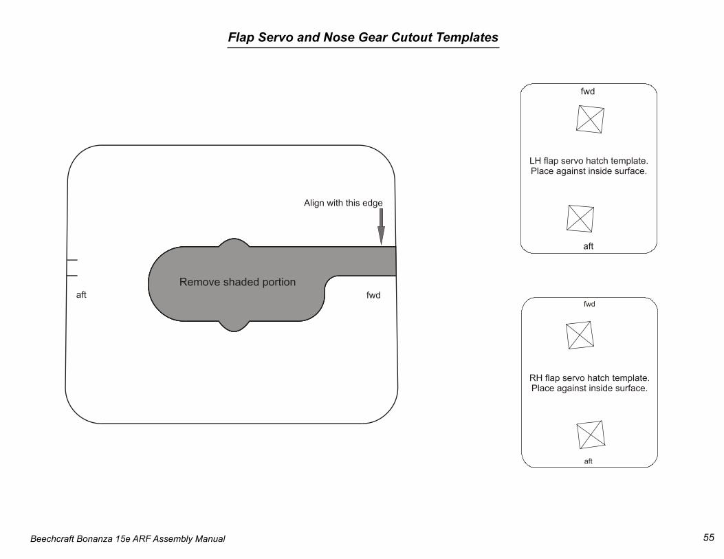
Flap Servo and Nose Gear Cutout Templates
fwd
aft
LH flap servo hatch template.Place against inside surface.
aft
fwd
RH flap servo hatch template.Place against inside surface.
Align with this edge
Remove shaded portionfwdaft
Beechcraft Bonanza 15e ARF Assembly Manual56
This Page Intentionally Blank
57Beechcraft Bonanza 15e ARF Assembly Manual
Warranty InformationWarranty PeriodExclusive Warranty- Horizon Hobby, Inc., (Horizon) warranties that the Products purchased (the “Product”) will be free from defects in materials and workmanship at the date of purchase by the Purchaser.
Limited Warranty(a) This warranty is limited to the original Purchaser (“Purchaser”) and is not transferable. REPAIR OR REPLACEMENT AS PROVIDED UNDER THIS WARRANTY IS THE EXCLUSIVE REMEDY OF THE PURCHASER. This warranty covers only those Products purchased from an authorized Horizon dealer. Third party transactions are not covered by this warranty. Proof of purchase is required for warranty claims. Further, Horizon reserves the right to change or modify this warranty without notice and disclaims all other warranties, express or implied.
(b) Limitations- HORIZON MAKES NO WARRANTY OR REPRESENTATION, EXPRESS OR IMPLIED, ABOUT NON-INFRINGEMENT, MERCHANTABILITY OR FITNESS FOR A PARTICULAR PURPOSE OF THE PRODUCT. THE PURCHASER ACKNOWLEDGES THAT THEY ALONE HAVE DETERMINED THAT THE PRODUCT WILL SUITABLY MEET THE REQUIREMENTS OF THE PURCHASER’S INTENDED USE.
(c) Purchaser Remedy- Horizon’s sole obligation hereunder shall be that Horizon will, at its option, (i) repair or (ii) replace, any Product determined by Horizon to be defective. In the event of a defect, these are the Purchaser’s exclusive remedies. Horizon reserves the right to inspect any and all equipment involved in a warranty claim. Repair or replacement decisions are at the sole discretion of Horizon. This warranty does not cover cosmetic damage or damage due to acts of God, accident, misuse, abuse, negligence, commercial use, or modification of or to any part of the Product. This warranty does not cover damage due to improper installation, operation, maintenance, or attempted repair by anyone other than Horizon. Return of any goods by Purchaser must be approved in writing by Horizon before shipment.
Damage Limits:HORIZON SHALL NOT BE LIABLE FOR SPECIAL, INDIRECT OR CONSEQUENTIAL DAMAGES, LOSS OF PROFITS OR PRODUCTION OR COMMERCIAL LOSS IN ANY WAY CONNECTED WITH THE PRODUCT, WHETHER SUCH CLAIM IS BASED IN CONTRACT, WARRANTY, NEGLIGENCE, OR STRICT LIABILITY. Further, in no event shall the liability of Horizon exceed the individual price of the Product on which liability is asserted. As Horizon has no control over use, setup, final assembly, modification or misuse, no liability shall be assumed nor accepted for any resulting damage or injury. By the act of use, setup or assembly, the user accepts all resulting liability.
If you as the Purchaser or user are not prepared to accept the liability associated with the use of this Product, you are advised to return this Product immediately in new and unused condition to the place of purchase.
Law: These Terms are governed by Illinois law (without regard to conflict of law principals). Safety Precautions:This is a sophisticated hobby Product and not a toy. It must be operated with caution and common sense and requires some basic mechanical ability. Failure to operate this Product in a safe and responsible manner could result in injury or damage to the Product or other property. This Product is not intended for use by children without direct adult supervision. The Product manual contains instructions for safety, operation and maintenance. It is essential to read and follow all the instructions and warnings in the manual, prior to assembly, setup or use, in order to operate correctly and avoid damage or injury.
Questions, Assistance, and Repairs:Your local hobby store and/or place of purchase cannot provide warranty support or repair. Once assembly, setup or use of the Product has been started, you must contact Horizon directly. This will enable Horizon to better answer your questions and service you in the event that you may need any assistance. For questions or assistance, please direct your email to [email protected], or call 877.504.0233 toll free to speak to a service technician. Inspection or RepairsIf this Product needs to be inspected or repaired, please call for a Return Merchandise Authorization (RMA). Pack the Product securely using a shipping carton. Please note that original boxes may be included, but are not designed to withstand the rigors of shipping without additional protection. Ship via a carrier that provides tracking and insurance for lost or damaged parcels, as Horizon is not responsible for merchandise until it arrives and is accepted at our facility. A Service Repair Request is available at www.horizonhobby.com on the “Support” tab. If you do not have internet access, please include a letter with your complete name, street address, email address and phone number where you can be reached during business days, your RMA number, a list of the included items, method of payment for any non-warranty expenses and a brief summary of the problem. Your original sales receipt must also be included for warranty consideration. Be sure your name, address, and RMA number are clearly written on the outside of the shipping carton.
Warranty Inspection and RepairsTo receive warranty service, you must include your original sales receipt verifying the proof-of-purchase date. Provided warranty conditions have been met, your Product will be repaired or replaced free of charge. Repair or replacement decisions are at the sole discretion of Horizon Hobby.
58 Beechcraft Bonanza 15e ARF Assembly Manual
Non-Warranty Repairs Should your repair not be covered by warranty the repair will be completed and payment will be required without notification or estimate of the expense unless the expense exceeds 50% of the retail purchase cost. By submitting the item for repair you are agreeing to payment of the repair without notification. Repair estimates are available upon request. You must include this request with your repair. Non-warranty repair estimates will be billed a minimum of ½ hour of labor. In addition you will be billed for return freight. Please advise us of your preferred method of payment. Horizon accepts money orders and cashiers checks, as well as Visa, MasterCard, American Express, and Discover cards. If you choose to pay by credit card, please include your credit card number and expiration date. Any repair left unpaid or unclaimed after 90 days will be considered abandoned and will be disposed of accordingly. Please note: non-warranty repair is only available on electronics and model engines.
United States:Electronics and engines requiring inspection or repair should be shipped to the following address:
Horizon Service Center4105 Fieldstone Road
Champaign, Illinois 61822USA
All other Products requiring warranty inspection or repair should be shipped to the following address:
Horizon Product Support4105 Fieldstone Road
Champaign, Illinois 61822USA
Please call 877-504-0233 or e-mail us at [email protected] with anyquestions or concerns regarding this product or warranty.
United Kingdom:Electronics and engines requiring inspection or repair should be shipped to the following address:
Horizon Hobby UKUnits 1-4 Ployters Rd
Staple TyeHarlow, Essex
CM18 7NSUnited Kingdom
Please call +44 (0) 1279 641 097 or e-mail us [email protected] with any questions orconcerns regarding this product or warranty.
Germany:Electronics and engines requiring inspection or repairs should be shipped to the following address:
Horizon Technischer ServiceHamburger Strasse 10
25335 ElmshornGermany
Please call +49 4121 46199 66 or e-mail us [email protected] with any questions orconcerns regarding this product or warranty.
Instructions for Disposal of WEEE byUsers in the European Union
This product must not be disposed of with other waste. Instead, it is the user’s responsibility to dispose of their waste equipment by handing it over to a designated collection point for the recycling of waste electrical and electronic equipment. The separate collection and recycling of your waste equipment at the time of disposal will help to conserve natural resources and ensure that it is recycled in a manner that protects human health and the environment. For more information about where you can drop off your waste equipment for recycling, please contact your local city office, your household waste disposal service or where you purchased the product.
59Beechcraft Bonanza 15e ARF Assembly Manual
Academy of Model AeronauticsNational Model Aircraft Safety Code
Effective January 1, 2010
GENERALA model aircraft shall be defined as a non-human-carrying aircraft capable of sustained flight in the atmosphere. It may not exceed limitationsestablished in this code and is intended to be used exclusively for sport, recreation, and/or competition.
1. I will not willfully fly my model aircraft in a careless or reckless manner, and will abide by this Safety Code and any additional rules specific to flying sites.2. I will yield the right-of-way to man-carrying aircraft and will see and avoid all aircraft, utilizing a spotter when appropriate. (See AMA Document #540-D on See and Avoid Guidance.)3. I will not fly my model aircraft higher than approximately 400 feet above ground level, when within three (3) miles of an airport without notifying the airport operator.4. The maximum takeoff weight of a model aircraft, including fuel, is 55 pounds, except for those flown under the AMA Experimental Aircraft Rules.5. I will not fly my model aircraft in sanctioned events, air shows, or model demonstrations unless I have previously proven that my aircraft, controlsystem, and piloting skills are adequate by successfully executing all maneuvers intended or anticipated in the specific event. If I am not aproficient pilot, I will not fly in these events unless assisted by an experienced pilot.6. I will not fly my model aircraft unless it is identified with my name and address, or AMA number, inside or affixed to the outside of the model aircraft. Thisdoes not apply to model aircraft flown indoors.7. I will not operate model aircraft with metal-blade propellers.8. I will not operate model aircraft carrying pyrotechnic devices which explode or burn, or any device, which propels a projectile of any kind. Exceptions include Free Flight fuses or devices that burn producing smoke and are securely attached to the model aircraft during flight. Rocket motors up to
a G-series size may be used, provided they remain firmly attached to the model aircraft during flight. Model rockets may be flown in accordance with the National Model Rocketry Safety Code; however, they may not be launched from model aircraft. Officially designated AMA Air Show Teams (AST) are authorized to use devices and practices as defined within the Team AMA Program Document.9. I will not operate my model aircraft while under the influence of alcohol or while using any drug which could adversely affect my ability to safely control the model.10. When and where required by rule, helmets must be properly worn and fastened. They must be OSHA, DOT, ANSI, SNELL or NOCSAE approved or comply with comparable standards.
RADIO CONTROL1. All pilots shall avoid flying models over unprotected people.2. I will complete a successful radio equipment ground-range check in accordance with the manufacturer’s recommendations before the first flight of a new or repaired aircraft.3. At all flying sites a safety line or lines must be established, in front of which all flying takes place. Only personnel associated with flying the model aircraft are allowed at or in front of the safety line. In the case of air shows or demonstrations a straight safety line must be established. An area away from the safety line must be maintained for spectators. Intentional flying behind the safety line is prohibited. (See AMA Document #706 for Recommended Field Layout.)4. I will operate my model aircraft using only radio-control frequencies currently allowed by the Federal Communications Commission (FCC). Only individuals properly licensed by the FCC are authorized to operate equipment on Amateur Band frequencies.5. I will not knowingly operate my model aircraft within three (3) miles of any preexisting flying site without a frequency-management agreement. (See AMA Document #922 for Testing for RF Interference. See AMA Document #923 for Frequency Management Agreement.)
6. With the exception of events flown under official AMA Competition Regulations rules, excluding takeoff and landing, no powered model may be flownoutdoors closer than 25 feet to any individual, except for the pilot and the pilot’s helper(s) located at the flight line.7. Under no circumstances may a pilot or other person touch a model aircraft in flight while it is still under power, except to divert it from striking an individual. This does not apply to model aircraft flown indoors.8. Radio-controlled night flying requires a lighting system that provides the pilot with a clear view of the model’s attitude and orientation at all times.9. The operator of a radio-controlled model aircraft shall control it during the entire flight, maintaining visual contact without enhancement other than bycorrective lenses that are prescribed for the pilot. First-Person View (FPV) flying may only be conducted in accordance with the procedures outlined in AMA Document #550.