Research Inventy: International Journal Of Engineering And Science Vol.4, Issue 5 (May 2014), PP 32-44 Issn (e): 2278-4721, Issn (p):2319-6483, www.researchinventy.com 32 Behavior on Shear Strengthening of Precraced/Repair RC Continuous Beams Using CFRP Strips 1 M.B.S Alferjani, 2 A.A. Abdul Samad, 3 Blkasem. S Elrawaff, 4 N. Mohamad 1, 2, 4 Faculty of Civil and Environmental Engineering, UTHM. Buto pahat, Malaysia 3 Faculty of Civil Engineering Omar Al Mukhtar University, ABSTRACT - This paper presents the results of an experimental investigation for enhancing the shear capacity of reinforced concrete (RC) continuous beams using different CFRP wrapping schemes. A total of five concrete beams were tested and various sheet configurations and layouts were studied to determine their effects on ultimate shear strength and shear capacity of the beams. One beam was kept as control beams, while other beams were precracked and repaired with CFRP strips (i.e. precracked/repaired) with four or three sides bonding. Tests result shows that the effectiveness and shear capacity of the CFRP strengthened specimens. The shear enhancement of the CFRP strengthened beams varied between 18% and 44% over the control beam. This study confirms that the CFRP strip technique significantly enhances the shear capacity of reinforced concrete shear beams. Two prediction models available in literature were used for computing the contribution of CFRP strips and compared with the experimental results. KEYWORDS - CFRP, Continuous Beam, Shear Strengthening I. INTRODUCTION Deterioration of concrete structures is one of the major problems of the construction industry today. Moreover, a large number of structures constructed in the past using the older design codes in different parts of the world are structurally unsafe according to today design codes [1]. Shear failure of RC beams, caused by their brittle nature, has been identified as the most disastrous failure mode, it occurred with no advance warning of distress. Shear deficiency may occur due to many factors such as insufficient shear reinforcement or reduction in steel area due to corrosion, increased service load and construction errors [2]. Bonding plates to the external surface of existing reinforced concrete elements have proved to be an effective and practical means of increasing strength and stiffness [3]. The use of externally bonded fiber reinforced polymer (FRP) reinforcement to strength reinforced concrete structures is becoming an increasingly popular retrofit technique. FRP is a composite material generally consisting of carbon, aramid or glass fibers in polymeric matrix [4]. This research focused on using Carbon Fiber Reinforced Polymer (CFRP) systems consisting of flexible sheets. The objective of this study were to investigate the effectiveness of using externally bonded CFRP strips in repair and strengthen of reinforced concrete continuous beams. II. SHEAR STRENGTH OF RC BEAM STRENGTHENED WITH FRP SHEET The nominal shear strength of RC beams strengthened with externally bonded FRP sheets can be computed by equation (1): f s c n V V V V (1) To compute the nominal shear strength as given in equation (1), it is important to quantify the contribution of CFRP reinforcement to the shear capacity f V . This study presents two models used to obtain f V .
Transcript
Research Inventy: International Journal Of Engineering And Science
Deterioration of concrete structures is one of the major problems of the construction industry today.
Moreover, a large number of structures constructed in the past using the older design codes in different parts of
the world are structurally unsafe according to today design codes [1]. Shear failure of RC beams, caused by their
brittle nature, has been identified as the most disastrous failure mode, it occurred with no advance warning of
distress. Shear deficiency may occur due to many factors such as insufficient shear reinforcement or reduction in
steel area due to corrosion, increased service load and construction errors [2]. Bonding plates to the external
surface of existing reinforced concrete elements have proved to be an effective and practical means of
increasing strength and stiffness [3]. The use of externally bonded fiber reinforced polymer (FRP) reinforcement
to strength reinforced concrete structures is becoming an increasingly popular retrofit technique. FRP is a
composite material generally consisting of carbon, aramid or glass fibers in polymeric matrix [4]. This research
focused on using Carbon Fiber Reinforced Polymer (CFRP) systems consisting of flexible sheets. The objective
of this study were to investigate the effectiveness of using externally bonded CFRP strips in repair and
strengthen of reinforced concrete continuous beams.
II. SHEAR STRENGTH OF RC BEAM STRENGTHENED WITH FRP SHEET
The nominal shear strength of RC beams strengthened with externally bonded FRP sheets can be computed by
equation (1):
fscn VVVV (1)
To compute the nominal shear strength as given in equation (1), it is important to quantify the contribution of
CFRP reinforcement to the shear capacity fV . This study presents two models used to obtain fV .
Behavior on Shear Strengthening of Precraced/Repair RC Continuous Beams Using CFRP Strips
33
I. KHALIFA MODEL (5) The contribution of externally bonded FRP sheets to the shear capacity of an RC beam may be
calculated from the equation 2.
s
wc
f
ffef
f Vdbf
s
dfAV
3
'2cossin
Because CFRP linearly elastic until failure, the effective stress may be computed as follows:
fufe Rff
1. Reduction Coefficient Based on CFRP Sheet Fracture Failure The reduction coefficient was established as a function of and expressed in
equation (4).
78.022.15622.02
ffff EER (4)
2. Reduction Coefficient Based on CFRP Debonding Failure After the shear cracks develops, only that portion of the width of CFRP extending past the crack by the
effective bonded length is assumed to be capable of carrying shear. The effective width feW based on the shear
crack angle of 45° and the wrapping scheme is expressed in equations (5-a) , (5-b) and (5-c)
ffe dW
If the sheet is wrapped around the beam entirely (5-a)
efffef LdW If the sheet is in the form of a U-wrap (5-b)
effffe LdW 2 If the sheet is bonded to only the sides of the beam (5-c)
If the sheets is in the form of U-wrap In determining the reduction coefficient for bond, the effective bond
length effL , has to be determined. The effective bond length effL , is a function of the thickness of the FRP sheet
and the elastic modulus of the FRP. As the stiffness of the sheet increases the effective bond length decreases.
)ln(5.0134.6 ff Et
eff eL
(6)
The final expression for the reduction coefficient R, for the mode of failure controlled by CFRP debonding is
expressed in Eq (7).
6
3/2
10156.69.199'
ff
ffu
fecuEt
d
WfR
(7)
The above equation is applicable for CFRP axial rigidity ff Et , ranging from 20 to 90 Gpa (kN/mm).
3. Upper Limit of the Reduction Coefficient In order to control the shear cracks width and loss of aggregate interlock, an upper limit of reduction
coefficient R was suggested.
ff E
Behavior on Shear Strengthening of Precraced/Repair RC Continuous Beams Using CFRP Strips
34
fu
R
006.0 (8)
The final reduction coefficient for the CFRP system is taken as the lowest value determined from the
two possible modes of failure and upper limit. Note, that if the sheet is wrapped entirely around the beam or an
effective anchor is used, the failure mode of CFRP debonding is not being considered. The reduction coefficient
is only controlled by CFRP fracture and upper limit.
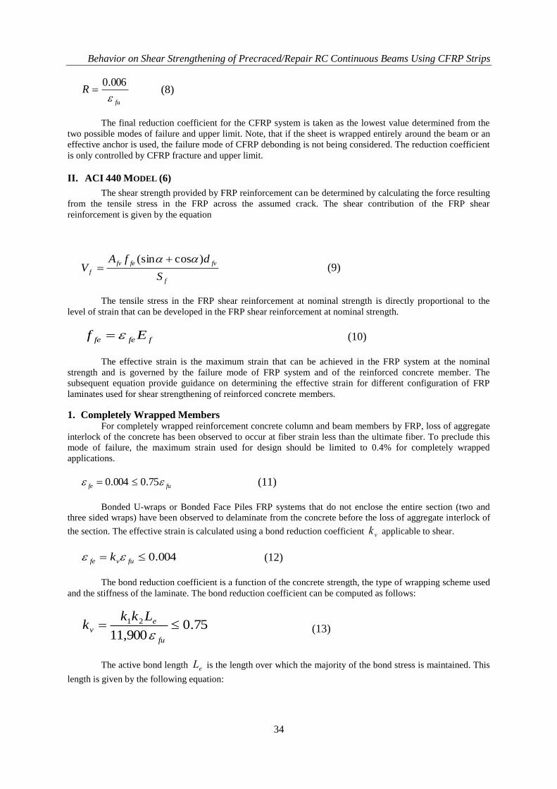
II. ACI 440 MODEL (6)
The shear strength provided by FRP reinforcement can be determined by calculating the force resulting
from the tensile stress in the FRP across the assumed crack. The shear contribution of the FRP shear
reinforcement is given by the equation
f
fvfefv
fS
dfAV
)cos(sin (9)
The tensile stress in the FRP shear reinforcement at nominal strength is directly proportional to the
level of strain that can be developed in the FRP shear reinforcement at nominal strength.
ffefe Ef
(10)
The effective strain is the maximum strain that can be achieved in the FRP system at the nominal
strength and is governed by the failure mode of FRP system and of the reinforced concrete member. The
subsequent equation provide guidance on determining the effective strain for different configuration of FRP
laminates used for shear strengthening of reinforced concrete members.
1. Completely Wrapped Members For completely wrapped reinforcement concrete column and beam members by FRP, loss of aggregate
interlock of the concrete has been observed to occur at fiber strain less than the ultimate fiber. To preclude this
mode of failure, the maximum strain used for design should be limited to 0.4% for completely wrapped
applications.
fufe 75.0004.0
(11)
Bonded U-wraps or Bonded Face Piles FRP systems that do not enclose the entire section (two and
three sided wraps) have been observed to delaminate from the concrete before the loss of aggregate interlock of
the section. The effective strain is calculated using a bond reduction coefficient vk applicable to shear.
004.0 fuvfe k
(12)
The bond reduction coefficient is a function of the concrete strength, the type of wrapping scheme used
and the stiffness of the laminate. The bond reduction coefficient can be computed as follows:
75.0900,11
21 fu
ev
Lkkk
(13)
The active bond length eL is the length over which the majority of the bond stress is maintained. This
length is given by the following equation:
Behavior on Shear Strengthening of Precraced/Repair RC Continuous Beams Using CFRP Strips
35
58.0)(
300,23
ff
eEnt
L
(14)
The bond reduction coefficient also relies on two modification factors 1k and 2k , that account for the
concrete strength and the type of wrapping scheme used. Expressions for these modification factors are given as
follows:
3/2
127
'
cf
k
(14)
fv
efv
d
Ldk
2 (For U-wraps) (15)
fv
efv
d
Ldk
22
(For two sides bonded) (16)
The nominal shear capacity of the strengthened beam can be calculated by using the equation:
)( fscn VVVV
(17)
An additional reduction factor ψ is applied to the shear contribution of the FRP reinforcement. The
reduction factor of 0.85 is recommended for three sides FRP U-wrap or two opposite sides strengthening and
0.95 for fully-wrapped members.
III. EXPERIMENTAL PROGRAM
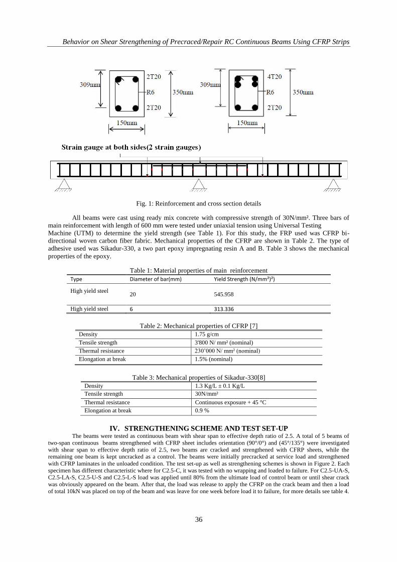
1. Test Specimens and Materials The experimental program consisted of testing five full-scale RC continuous beams under four-point
loading. All specimens were design according to BS 8110: Part 1: 1997 with identical size of 150x350x5800
mm. All beams have an identical reinforcement details including longitudinal reinforcement in the form of 20
mm and stirrups reinforcement of 6 mm size at 200mm spacing centre to centre. Figure 1 below shows specimen
details and the place of strain gauge on reinforcement.
Behavior on Shear Strengthening of Precraced/Repair RC Continuous Beams Using CFRP Strips
36
Fig. 1: Reinforcement and cross section details
All beams were cast using ready mix concrete with compressive strength of 30N/mm². Three bars of
main reinforcement with length of 600 mm were tested under uniaxial tension using Universal Testing
Machine (UTM) to determine the yield strength (see Table 1). For this study, the FRP used was CFRP bi-
directional woven carbon fiber fabric. Mechanical properties of the CFRP are shown in Table 2. The type of
adhesive used was Sikadur-330, a two part epoxy impregnating resin A and B. Table 3 shows the mechanical
properties of the epoxy.
Table 1: Material properties of main reinforcement
Type Diameter of bar(mm) Yield Strength (N/mm²)²)
High yield steel
20 545.958
High yield steel 6 313.336
Table 2: Mechanical properties of CFRP [7]
Density 1.75 g/cm
Tensile strength 3'800 N/ mm² (nominal)
Thermal resistance 230‟000 N/ mm² (nominal)
Elongation at break 1.5% (nominal)
Table 3: Mechanical properties of Sikadur-330[8]
Density 1.3 Kg/L ± 0.1 Kg/L
Tensile strength 30N/mm²
Thermal resistance Continuous exposure + 45 °C
Elongation at break 0.9 %
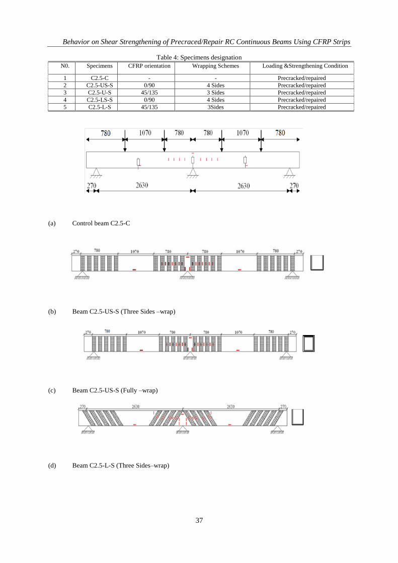
IV. STRENGTHENING SCHEME AND TEST SET-UP The beams were tested as continuous beam with shear span to effective depth ratio of 2.5. A total of 5 beams of
two-span continuous beams strengthened with CFRP sheet includes orientation (90°/0°) and (45°/135°) were investigated
with shear span to effective depth ratio of 2.5, two beams are cracked and strengthened with CFRP sheets, while the
remaining one beam is kept uncracked as a control. The beams were initially precracked at service load and strengthened
with CFRP laminates in the unloaded condition. The test set-up as well as strengthening schemes is shown in Figure 2. Each
specimen has different characteristic where for C2.5-C, it was tested with no wrapping and loaded to failure. For C2.5-UA-S,
C2.5-LA-S, C2.5-U-S and C2.5-L-S load was applied until 80% from the ultimate load of control beam or until shear crack
was obviously appeared on the beam. After that, the load was release to apply the CFRP on the crack beam and then a load
of total 10kN was placed on top of the beam and was leave for one week before load it to failure, for more details see table 4.
Behavior on Shear Strengthening of Precraced/Repair RC Continuous Beams Using CFRP Strips
Behavior on Shear Strengthening of Precraced/Repair RC Continuous Beams Using CFRP Strips
38
(e) Beam C2.5-LS-S (Three Sides–wrap)
Fig. 2: Test set-up and strengthening schemes
V. EXPERIMENTAL RESULTS
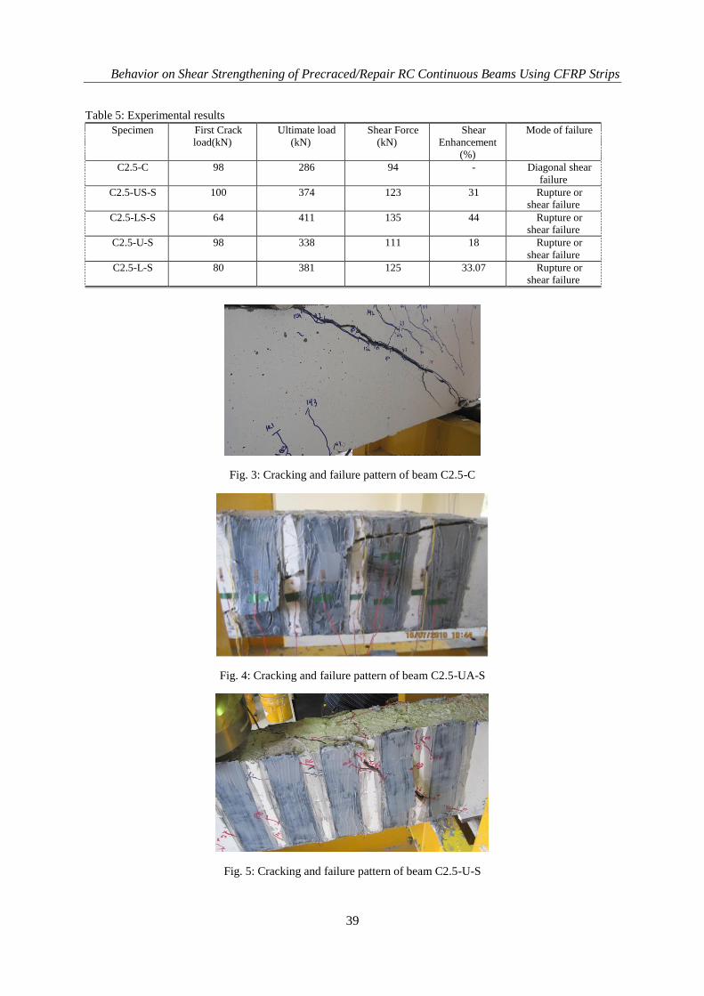
1. Ultimate Load and Modes of Failure All specimens failed in shear as expected. For control beam, C2.5-C, flexural cracks were started to
form at near the mid span at the bottom of the beam at a load approximately 98kN. The shear cracks began to
appear at a load of approximately 102Kn and as the load increased, the shear crack widened and propagated up
to the final failure at a load level of 286kN. The mode of failure was shear crushing of the concrete. Specimen
C2.5-U-S was loaded to 224kN in first cycle of loading then unloaded to zero. The first flexural crack was
occurred at 98kN. As the load increased, the flexural cracks were initially appeared and the diagonal shear crack
was observed near the middle of the shear span at a load of 196kN. After completing the pre-cracking phase, the
beam was strengthened with U-wrapped CFRP strips and sustained with 10kN load for one week. Again the
beam was loaded but up to failure. The diagonal cracks were clearly observed at a load of 148kN. The failure
mode of the beam occurred at a total applied load of 338kN which is the fracture of CFRP strips along the shear
crack. The percentage of ultimate load enhancement was 18% higher than the value of the control beam C2.5-C
(see Figure 3 to6). For beam C2.5-UA-S, which was strengthened with CFRP strips, fully wrap (U-wrap) and
oriented at 90°/0°, the failure mode of this beam was rupture-shear of CFRP as shown in Figure 4.3. In this
beam, the diagonal shear crack was observed at total load of about 212kN. The first crack was observed total
load of 100kN. As the load increased, more shear cracks appeared throughout the shear span. When the total
load reached 374kN, the contribution of CFRP to shear capacity was 88kN and increased in shear enhancement
at 31% higher than the control beam. For beam C2.5-LA-S, which was fully-wrapped (L-wrap) and oriented at
45°/135° with CFRP strips, no cracks were visible on the sides of the beam until 100kN. A diagonal shear crack
was observed near the middle of shear spans at a load of 164kN. Finally, the beam failed at a total load of
411kN. Test results shows that there was an increase of 44% in ultimate load capacity compared to control beam
C2.5-C. The failure mode of this beam was rupture-shear of CFRP and the contribution of CFRP to the shear
capacity was 125kN as shown in Figure 4.5. In specimens C2.5-U-V2 which was fully-wrapped (L-wrap) and
oriented at 45°/135° with CFRP strips, the first crack was occurred at 80kN. The diagonal shear cracks were
observed at 180kN and the failure of the specimen occurred when the total applied load reaches 381kN. This
was an increase of 45% in ultimate load capacity compared to the control beam C2.5-C. The cracks initiated at
the location of the supports and extended towards the applied load. At failure, the concrete cover on the topside
was extensively damaged. Figure 4.5 shows the shear-CFRP rupture-shear failure of the specimen.
Behavior on Shear Strengthening of Precraced/Repair RC Continuous Beams Using CFRP Strips
39
Table 5: Experimental results
Specimen First Crack
load(kN)
Ultimate load
(kN)
Shear Force
(kN)
Shear
Enhancement
(%)
Mode of failure
C2.5-C 98 286
94 - Diagonal shear
failure
C2.5-US-S 100 374
123 31 Rupture or
shear failure
C2.5-LS-S 64 411 135 44 Rupture or
shear failure
C2.5-U-S 98 338
111 18 Rupture or
shear failure
C2.5-L-S 80 381 125 33.07 Rupture or
shear failure
Fig. 3: Cracking and failure pattern of beam C2.5-C
Fig. 4: Cracking and failure pattern of beam C2.5-UA-S
Fig. 5: Cracking and failure pattern of beam C2.5-U-S
Behavior on Shear Strengthening of Precraced/Repair RC Continuous Beams Using CFRP Strips
40
Fig. 6: Cracking and failure pattern of beam C2.5-L-S
2. LOAD-DISPLACEMENT BEHAVIOR Figure 7and 8 shows the total applied load versus mid-span deflection relationship for all tested
specimens. All beams showed very similar stiffness trend to each other. The smallest deflection was observed
for beam C2.5-C. After the occurrence of the first crack, in precracked and repaired phase the specimen C2.5-
LA-S had the greatest stiffness because of orientation of CFRP. It was also observed that the stiffness of the
beam strengthened with orientation 90 degree of CFRP (C2.5-UA-S and C2.5-U-S) was less than that of the
beam strengthened with orientation 45degree (C2.5-LA-S and C2.5-L-S). The ultimate load was greater for
specimen C2.5-LA-S compared to other specimens. Specimens C2.5-C, C2.5-LA-S , C2.5-UA-S, C2.5-L-S and
C2.5-U-S had observed a maximum deflection of 10.87mm, 12.895mm,10.86mm, 11.29mm and 10.84mm at
failure load.
Fig. 7: Ultimate load versus mid-span displacement relationship
Fig. 8: Ultimate load versus mid-span displacement relationship
Behavior on Shear Strengthening of Precraced/Repair RC Continuous Beams Using CFRP Strips
41
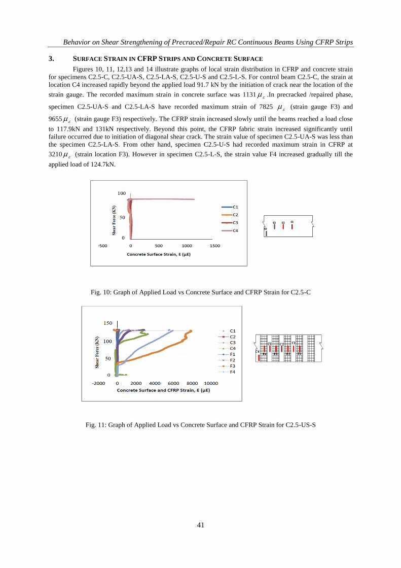
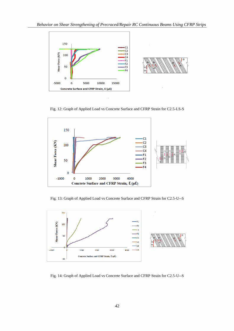
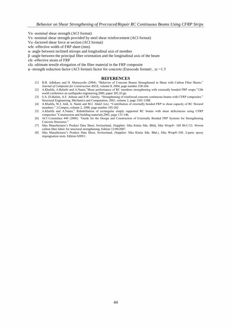
3. SURFACE STRAIN IN CFRP STRIPS AND CONCRETE SURFACE
Figures 10, 11, 12,13 and 14 illustrate graphs of local strain distribution in CFRP and concrete strain
for specimens C2.5-C, C2.5-UA-S, C2.5-LA-S, C2.5-U-S and C2.5-L-S. For control beam C2.5-C, the strain at
location C4 increased rapidly beyond the applied load 91.7 kN by the initiation of crack near the location of the
strain gauge. The recorded maximum strain in concrete surface was 1131 .In precracked /repaired phase,
specimen C2.5-UA-S and C2.5-LA-S have recorded maximum strain of 7825 (strain gauge F3) and
9655 (strain gauge F3) respectively. The CFRP strain increased slowly until the beams reached a load close
to 117.9kN and 131kN respectively. Beyond this point, the CFRP fabric strain increased significantly until
failure occurred due to initiation of diagonal shear crack. The strain value of specimen C2.5-UA-S was less than
the specimen C2.5-LA-S. From other hand, specimen C2.5-U-S had recorded maximum strain in CFRP at
3210 (strain location F3). However in specimen C2.5-L-S, the strain value F4 increased gradually till the
applied load of 124.7kN.
Fig. 10: Graph of Applied Load vs Concrete Surface and CFRP Strain for C2.5-C
Fig. 11: Graph of Applied Load vs Concrete Surface and CFRP Strain for C2.5-US-S
Behavior on Shear Strengthening of Precraced/Repair RC Continuous Beams Using CFRP Strips
42
Fig. 12: Graph of Applied Load vs Concrete Surface and CFRP Strain for C2.5-LS-S
Fig. 13: Graph of Applied Load vs Concrete Surface and CFRP Strain for C2.5-U--S
Fig. 14: Graph of Applied Load vs Concrete Surface and CFRP Strain for C2.5-U--S
Behavior on Shear Strengthening of Precraced/Repair RC Continuous Beams Using CFRP Strips
43
VI. THE COMPARISON OF EXPERIMENTAL AND THEORETICAL RESULTS The comparison of experimental and theoretical results of the control and precracked/repaired
continuous beams are shown in Table 6. The shear capacity contributed by the external CFRP reinforcement
was estimated by subtracting the shear strength of the reference beam from the CFRP strengthened beam. The
strip technique had proved that the shear capacities of the precracked/repaired continuous beams ranging from
18% to 44% over the control beam. The shear capacity of these continuous beams was theoretically computed
using ACI 440 Format and Khalifa Model. The shear strength of the strengthened beams is computed by adding
the contribution of shear strength of external CFRP reinforcement „Vf‟. It can be seen that the experimental
values of the strengthened for all beams C2.5-C, C2.5-US-S, C2.5-LS-S, C2.5-U-S, and C2.5-L-S. From the
overall discussion, it can be concluded that the predicted theoretical results of the continuous beams especially
ACI model shows reasonable accuracy with the experimental results.
Table 6: Comparision of Experimental and Theoretical results Specimens Theoretical value Exp.
Results
theoryf
f
V
V
,
exp,
fV
KN exp,fV
KN
Khalifa Model ACI 440
Model
Khalifa Model ACI 440 Model
C2.5-C - - - - -
C2.5-US-S 46.1 27.9 29 0.63 1.04
C2.5-LS-S 65.18 39.45 41 0.63 1.04
C2.5-U-S 46.1 27.9 17 0.37 0.61
C2.5-L-S 62.9 39.45 31 0.5 0.79
VII. CONCLUSION The test results indicated that strengthening of RC continuous beams using externally bonded CFRP
strips can be used to enhance the shear capacity of continuous T-beams. For beams tested in the experimental
program, the shear capacity increased at a ranged from 18% to 44 %. An increase in number of layer of CFRP
strips has resulted in stiffer and stronger beams. It was also observation and analysis of strain of CFRP strips,
repaired beams have shown an obvious increased of CFRP strain. The elongation of strain in CFRP due to the
weaken condition and pre-cracked prior to being wrapped with CFRP strips. The elongation of CFRP shows an
effectiveness of the CFRP in resisting the sheer force of the beam. However, the magnitude of the strain on the
location of strain gauge with respect to crakes.
ACKNOWLEDGMENT The authors gratefully acknowledge the financial supports from Fundamental Research Grant Scheme
(FRGS) funded by Ministry of Higher Education, Malaysia.
NOTATION
av- shear span
Af -area of CFRP shear reinforcement = 2 tf wf
bw -width of the web of beam cross section (ACI format)
d -depth from the top of the section to the tension steel reinforcement centroid
df -effective depth of the CFRP shear reinforcement (usually equal to d for rectangular sections and d-ts for T-
sections)
Ef -elastic modulus of FRP (GPa)
f 'c -nominal concrete compressive strength in MPa (ACI format)
ffu -ultimate tensile strength of the FRP sheet in the direction of the principal fibers
fy -yield strength of steel reinforcement
Le -effective bond length (mm)
R -reduction coefficient (ratio of effective average stress or strain in the FRP sheet to its ultimate strength or
elongation)
s -spacing of steel stirrups
sf -pacing of FRP strips
tf -thickness of the FRP sheet on one side of the beam (mm)
REFERENCES [1] B.B. Adhikary and H. Mutsuyoshi (2004). “Behavior of Concrete Beams Strengthened in Shear with Carbon Fiber Sheets,”
Journal of Composite for Construction ASCE, volume 8, 2004, page number 258-264. [2] A.Khalifa, A.Belarbi and A.Nanni,”Shear performance of RC members strengthening with externally bonded FRP wraps.”12th
world conference on earthquake engineering,2000, paper 305,10 pp.
[3] S.A. El-Rafaie, A.F. Ashour and S.W. Garrity, “Strengthening of reinforced concrete continuous beams with CFRP composites.”
Structural Engineering, Mechanics and Computation, 2001, volume 2, page 1591-1598.
[4] A.Khalifa, W.J. Jold, A. Nanni and M.I. Abdel Aziz, “Contribution of externally bonded FRP to shear capacity of RC flexural
members.” J.Compos.,volume 2, 1998, page number 195-202 [5] A.Khalifa and A.Nanni,” Rehabilitation of rectangular simply supported RC beams with shear deficiencies using CFRP
composites.”Construction and building materials,2002, page 135-146.
[6] ACI Committee 440 (2008). “Guide for the Design and Construction of Externally Bonded FRP Systems for Strengthening Concrete Structures.”
[7] Sika Manufacturer‟s Product Data Sheet, Switzerland, (Supplier: Sika Kimia Sdn. Bhd), Sika Wrap®- 160 BI-C/15. Woven
carbon fiber fabric for structural strengthening. Edition 11/09/2007. [8] Sika Manufacturer‟s Product Data Sheet, Switzerland, (Supplier: Sika Kimia Sdn. Bhd.), Sika Wrap®-330. 2-party epoxy