Behavior Research Methods & Instrumentation 1975. Vol. 7 (5).455-458 A device for inverting the visual field of animals JOHN ZIMMERMAN, MARTIN REITE, and JOHANN STOYVA Department ofPsychiatry, University of ColoradoMedical Center, Denver, Colorado80220 A device for inverting the visual field of small animals is described. Binocular lenses are mounted in a lightweight, aluminum frame which, in turn. is secured to a surgically attached. dental acrylic skull cap. The construction of the device. and its usefulness when simultaneous electrophysiological recordings are desired, is described by illustrating the details of fabricating such a device for a cat. Studies of the perceptual processes that underlie spatial localization and visual-motor coordination have frequently employed spatially rearranged visual feedback. In fact. the use of inverted. reversed, or displaced images in the study of perceptual adaptation dates back to at least the 19th century (Helmholtz. 1924. 1962; Stratton. 1897). Although the considerable body of literature that has resulted from these studies will not be dealt with in this short paper. a number of excellent reviews and theoretical sources are available (Carr. 1935. 1966; Canon. 1970; Day & Singer. 1967; Ewert. 1930. 1936. 1937; Foley, 1938; Harris. 1965; Held & Freedman. 1963; Hershberger & Carpenter. 1972; Howard & Templeton. 1966; Kohler. 1964; Smith & Smith. 1962; Starch. 1910; Taylor. 1962). Since perceptual adaptation to distorted vision involves physiological processes. the multidisciplinary approach of biopsychology. particularly the tech- niques of neurophysiologists. may be able to provide valuable information regarding the psychophysio- logical mechanisms underlying this complex phenomenon. Some recent animal experiments relating the effect of altered visual experience to changes in the neural substrate of the visual pathways, and to corresponding electrophysiological changes, illustrate the practicality of the neurophysi- ological approach (Blakemore & Cooper. 1970; Hirsch & Spinelli. 1971; Hubel & Wiesel. 1959. 1962). Unfortunately. the use of animals as subjects for distorted vision experiments has been somewhat hindered by the lack of an adequate design for constructing a lightweight easily tolerated device that can be worn by an animal to alter its visual input. This paper describes a device for inverting the visual field of a cat in a way that is not only compatible with long-term electrophysiological recordings but is an integral part of such procedures. THE SKULLCAP Previous attempts to force animals to wear vision-distorting devices have utilized masks. made of Supported by United States Public Health Service. National Institutes of Mental Health. Grant No. MH·1CJCJ73. various materials. which were held in place by means of a supporting leather headgear. One such device. used for spatially displacing the visual image of chicks. was described bv Hess (1956). Other devices., developed for cats. have 'been used to color filter visual input (Robinson & Voneida. 1962) or to selectively pattern the visual input (Hirsch & Spinelli. 1971), Foley (1940) was the first person to make use of a comparatively rigid aluminum frame to position an inverting lens system in front of a monkey's eyes. Even this device. however. relied on a less than optimal means 01 support since it was "held in place by a leather headgear fastened with straps and surgical adhesive (Foley. 1940)." Substantial improvement in the stability 01 the spatially rearranged image can be achieved by developing a rigid frame. securely attached to the animal's head so that the optics (prisms or lenses) can be precisely positioned in front of each eve. We have designed and constructed such a device. Details of construction are shown in Figures 1 to 4. The completed unit may be seen in Figure 5. A key feature of the device is that. to insure stability. the frame is secured to a dental acrylic skull cap! that is surgically attached to the head as shown in Figure 1. Embedded in the skull cap are sockets connected to implanted depth and surface electrodes to monitor the electroencephalogram (EEG). the electromyogram (EMG). and the electrooculogram (EOG). The skull cap is cast from a common dental acrylic which is poured into a hollow rectangular mold 25 mm high and having inside dimensions of approximately 25 x 40 mm. The mold need be no thicker than 5 rom. and the bottom surface of it should be shaped to conform to the top of the animal's head. The mold should either be made of or sprayed with a nonstick compound such as Tenon. The surgical procedure for attaching the acrylic cap is relatively straightforward. With the animal under general anesthesia. and with its head positioned in a stereotaxic unit. a S-b-cm longitudinal midline incision is made. the scalp retracted. and the periosteum scraped away. Five or six No. 4·40 stainless steel screws are placed into holes drilled into (but not through) the skull with a dental drill. The 455
Transcript
Behavior Research Methods & Instrumentation1975. Vol. 7 (5).455-458
A device for inverting the visual field of animals
JOHN ZIMMERMAN, MARTIN REITE, and JOHANN STOYVADepartment of Psychiatry, University of ColoradoMedical Center, Denver, Colorado 80220
A device for inverting the visual field of small animals is described. Binocular lenses are mounted in alightweight, aluminum frame which, in turn. is secured to a surgically attached. dental acrylic skull cap.The construction of the device. and its usefulness when simultaneous electrophysiological recordings aredesired, is described by illustrating the details of fabricating such a device for a cat.
Studies of the perceptual processes that underliespatial localization and visual-motor coordinationhave frequently employed spatially rearranged visualfeedback. In fact. the use of inverted. reversed, ordisplaced images in the study of perceptualadaptation dates back to at least the 19th century(Helmholtz. 1924. 1962; Stratton. 1897). Althoughthe considerable body of literature that has resultedfrom these studies will not be dealt with in this shortpaper. a number of excellent reviews and theoreticalsources are available (Carr. 1935. 1966; Canon. 1970;Day & Singer. 1967; Ewert. 1930. 1936. 1937; Foley,1938; Harris. 1965; Held & Freedman. 1963;Hershberger & Carpenter. 1972; Howard &Templeton. 1966; Kohler. 1964; Smith & Smith.1962; Starch. 1910; Taylor. 1962).
Since perceptual adaptation to distorted visioninvolves physiological processes. the multidisciplinaryapproach of biopsychology. particularly the techniques of neurophysiologists. may be able to providevaluable information regarding the psychophysiological mechanisms underlying this complexphenomenon. Some recent animal experimentsrelating the effect of altered visual experience tochanges in the neural substrate of the visualpathways, and to corresponding electrophysiologicalchanges, illustrate the practicality of the neurophysiological approach (Blakemore & Cooper. 1970;Hirsch & Spinelli. 1971; Hubel & Wiesel. 1959.1962). Unfortunately. the use of animals as subjectsfor distorted vision experiments has been somewhathindered by the lack of an adequate design forconstructing a lightweight easily tolerated device thatcan be worn by an animal to alter its visual input. Thispaper describes a device for inverting the visual field ofa cat in a way that is not only compatible with long-termelectrophysiological recordings but is an integral partof such procedures.
THE SKULLCAP
Previous attempts to force animals to wearvision-distorting devices have utilized masks. made of
Supported by United States Public Health Service. NationalInstitutes of Mental Health. Grant No. MH·1CJCJ73.
various materials. which were held in place by meansof a supporting leather headgear. One such device.used for spatially displacing the visual image ofchicks. was described bv Hess (1956). Other devices.,developed for cats. have 'been used to color filter visualinput (Robinson & Voneida. 1962) or to selectivelypattern the visual input (Hirsch & Spinelli. 1971),Foley (1940) was the first person to make use of acomparatively rigid aluminum frame to position aninverting lens system in front of a monkey's eyes. Eventhis device. however. relied on a less than optimalmeans 01 support since it was "held in place by aleather headgear fastened with straps and surgicaladhesive (Foley. 1940)." Substantial improvement inthe stability 01 the spatially rearranged image can beachieved by developing a rigid frame. securelyattached to the animal's head so that the optics(prisms or lenses) can be precisely positioned in frontof each eve.
We have designed and constructed such a device.Details of construction are shown in Figures 1 to 4.The completed unit may be seen in Figure 5. A keyfeature of the device is that. to insure stability. theframe is secured to a dental acrylic skull cap! that issurgically attached to the head as shown in Figure 1.Embedded in the skull cap are sockets connected toimplanted depth and surface electrodes to monitor theelectroencephalogram (EEG). the electromyogram(EMG). and the electrooculogram (EOG). The skullcap is cast from a common dental acrylic which ispoured into a hollow rectangular mold 25 mm highand having inside dimensions of approximately 25 x40 mm. The mold need be no thicker than 5 rom. andthe bottom surface of it should be shaped to conformto the top of the animal's head. The mold shouldeither be made of or sprayed with a nonstickcompound such as Tenon.
The surgical procedure for attaching the acrylic capis relatively straightforward. With the animal undergeneral anesthesia. and with its head positioned in astereotaxic unit. a S-b-cm longitudinal midlineincision is made. the scalp retracted. and theperiosteum scraped away. Five or six No. 4·40stainless steel screws are placed into holes drilled into(but not through) the skull with a dental drill. The
455
456 ZIMMERMAN, REITE, AND STOYVA
Figure 1. Surgically attached skull cap secured to top of cat'shead. Note holes drUled into sides and end of skull cap to accept setscrews In the metal frame (see Figure 3). Sockets visible at the topof the skull cap allow matching plugs to be quickly connected toimplanted electrodes for electrophysiological recordings.
exposed skull should then be thoroughly cleaned witha 3% solution of hydrogen peroxide and allowed todry. The prefabricated mold is placed on the top ofthe skull and a thick mixture of the dental acrylicprepared. The mixture is then poured into the mold(and arou nd the sockets if electrophysiologicalrecordings are to be made) to a level a few millimetersfrom the top. After the material has set and the moldhas been pried off, the scalp is sutured to conform tothe shape of the skull cap. Excess skin may betrimmed away.
THE ALUMINUM FRAME
The basic frame is designed to fit over and beattached to the skull cap. The frame is constructedfrom a single piece of 18-ga aluminum sheet metal,measuring about 15 cm square (for a cat).Construction is as follows: first, form a rectangularopening, the exact size of the skull cap, near one edgeof the flat piece of metal (as shown in Figure 2) bybending out four sides separated by cuts between
them. Next, bend, cut, and shape the frame to coverthe top, front, and sides of the eat's head. Use anepoxy glue to cement all overlapping sectionstogether, both on the inside and the outside surfacesof the frame, to insure a structurally rigid unit. Drillseveral small holes through the sides of the skull capopening of the frame and mark the location of theseholes on the skull cap itself. Drill slightly larger holesat these locations and use a tap wrench to thread theholes in the frame so that set screws can be used tosecurely attach the frame to the skull cap.
Then, position the frame on the cat and mark theapproximate position of the center of each eye on thefront of the frame; remove it, and drill two 1/2-in."pilot" holes at these locations. Again place the frameon the cat, screwing it onto the skull cap to position itprecisely, and look through these two "pilot" holes todetermine the true position of the center of each eye.Scratch four cross marks on the outside surface of theframe that would intersect at the exact center of eacheye when the cat is looking straight ahead. This ismost easily accomplished if the cat is mildly sedated.Remove the frame again and drill two l-in. holescentered on these marks. The completed frame shouldresemble the one shown in Figure 3.
THE INVERTING LENS SYSTEM
We used a telescope eyepiece containing a lens that isboth fairly large in diameter (permitting a relativelylarge field of view) and that has a relatively short focallength, so that two such lenses mounted in a tube andseparated by a distance equal to the sum of their focallengths is not unduly long.! This lens is amodified design 16-mm Konig formula. Each lens is athree-element system, consisting of a singlet, adoublet, and another singlet. According to themanufacturer, the lenses are free from chromatic and
Figure 2. Single piece of aluminum sheet metal, about 15 emsquare, with four flaps bent out 90 deg from the surface to form arectangular opening the exact size of the skull cap.
Figure 3. Metal frame after it has been shaped to cover the top,front, and sides of the cat's head. Note cutout portions for the eat'sears, eyes, and nose. Sides of slmU cap opening have been drilledand threaded to accept six small set screws which are screwed intomatching holes drilled into the skull cap on the eat's head(SeeFigure I).
spherical aberrations. and the image field is flat andfree from distortion.
Four such complex lenses are necessary to constructtwo image-inverting systems that rotate the visualarray 180 deg and that have near unit magnification.Two hollow aluminum tubes, measuring 6 em longand having a 2S.4-mm outside diam, with a S-mminner lip at one end (as shown in Figure 4), should bemachined to accept the lenses. The 11!4-in. outsidediam barrel that comes with each lens can bediscarded.
After the ocular tubes have been fabricated, butbefore mounting the lenses, the tubes should be madean integral part of the frame. Using a quick-acting(S-min) epoxy, each tube is temporarily glued to theframe in such a way that when the frame is securelyattached to the skull cap, each tube is exactly centeredupon and parallel with the optic axis. We chose tomount the tubes in a straight ahead position (parallelto each other) to allow the cat to fixate on relativelydistant objects. However, the tubes can be tiltedtowards each other by any desired amount to facilitateconvergence so that the cat can easily focus on nearbyobjects. Again it is advisable to work with a mildlysedated animal in order that this process be carriedout as accurately as possible.
After the epoxy has partially dried, slight changesin the position and orientation of each tube can bemade, if necessary, to accurately position thedirection of the tube along the desired visual pathway
VISION INVERTING DEVICE FOR ANIMALS 457
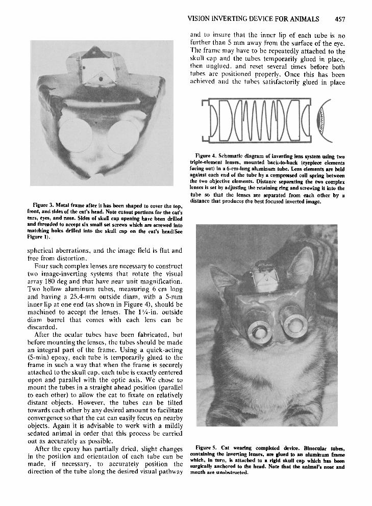
and to insure that the inner lip of each tube is nofurther than 5 mm away from the surface of the eye.The frame may have to be repeatedly attached to theskull cap and the tubes temporarily glued in place,then unglued. and reset several times before bothtubes are positioned properly. Once this has beenachieved and the tubes satisfactorily glued in place
Figure 4. Schematic diagram of inverting lens system using twotriple.element lenses, mounted back-to-baek (eyepiece elementsfacing out) in a 6-cm-long aluminum tube. Lens elements are heldagainst each end of the tube by a compressed coil spring betweenthe two objective elements. Distance separating the two complexlenses is set by adjusting the retaining ring and screwing It into thetube so that the lenses are separated from each other by adistance that produces the best focused inverted image.
Figure S. Cat wearing completed device. Binocular tubes,containing the inverting lenses, are glued to an aluminum framewhich, In turn, Is attached to a rigid skull cap which has beensurgically anchored to the head. Note that the animal's nose andmouth are unobstructed.
458 ZIMMERMAN, REITE, AND STOYVA
with the S-min epoxy. they can then be permanentlyattached to the frame using an industrial-strengthepoxy applied at the tube-frame interface both on theinside and outside surfaces of the frame. Accuratepositioning of the tubes with respect to the center ofeach eye is very important to insure a clear. sharplyfocused inverted image.
After the epoxy has cured overnight. the lensesshould be carefully inserted into each tube andarranged as illustrated in Figure 4. A large springthat barely tits into the inside of the tube separates thetwo complex lenses from each other and holds eachlens in place. one against the inner-lip portion of thetube and the other against a retaining ring threadedinto the opposite end. The distance separating theoptical centers of these two lenses is dependent uponhow far the retaining ring is screwed into the tube; itshould be set to that distance which produces thesharpest. most clearly defined inverted image. Also.the magnitication of each lens-system tube should beequal. This can be accomplished by lookingbinocularly at a ruler with a lens tube before one eye.The retaining ring may then be adjusted so that theruler viewed through the tube, and the ruler vieweddirectly, subtend the same visual angle.
The completed device. shown attached to the cat inFigure 5, weighs only 6 oz. It offers a reasonably largefield of view of over 55 deg for each eye, with excellentclarity of the inverted image; and it can be wornalmost indefinitely. 3 Since the device becomes anintegral part of the cat when it is screwed onto theskull cap. it not only resists efforts by the cat todislodge it but also maintains the lenses accuratelypositioned in front of each eye.
REFERENCES
BLAKEMORE. C. &: COOPER. G. F. Development of thebrain depends on the visual environment, Nature (London).1970. 228.477-478.
CANON. L. K, Intermodalitv inconsistency of input and directedattention as determinants of the nature of adaptation. Journal ofExperimentul Psychology. 1970.84. 141-147.
CARR. H. A. An introduction to space perception. New York:Hafner. 1%6 (Originally published 1935). Pp. 59-91.
DAY. R. H.. &: SINGER. G. Sensory adaptation andbehavioral compensation with spatially transformed vision andhearing. Psychological Bulletin. 1%7. 67. 307-322.
EWERT. P. H. A study of the effect of inverted retinal stimulation upon spatially coordinated behavior. Genetic PsychologyMonographs. 1930. 7. 177-363.
EWERT. P. H. Factors in space localization during invertedvision: I. Interference. Psychological Review. 1936. 43.522-546.
EWERT. P. H. Factors in space localization during invertedvision: II. An explanation of interference and adaptation.Psychological Review, 1937. 44. 105-116.
FOLEY. J. P. Empirical approaches to the problem of spaceperception. Psychological Bulletin. 1938. 35. 409-422.
FOLEY. J. P. An experimental investigation of the effectof prolonged inversion of the visual field in the rhesus
monkey (Macueu Muluttui .Journul ot Genetic Psvchology, 1940.56.21-51.
HARRIS. C. S. Perceptual adaptation to inverted. reversedand displaced vision. Psychological Revic11'. 1%5. 72.419-444.
HELD. R.. & FREEDMAN. S. J. Elasticity in humansensorimotor control. Science. 1%3. 142. 455-462.
HELMHOLTZ. H. L. F.. YON. Treatise on physiological optics(Vol, 3)(1. P. C. Southall. Ed. and trans.). New York:Dover. 1%2. (Originally published by Optical Societyof America. 1924.)
HERSHBERGER. W. A.. & CARPENTER. D. L. Adaptation toinverted retinal polarity: What's up. Bishop Berkeley?Journal otExperimental Psychology. 1972. 94. 261-268.
HEss. ECKHARD H. Space perception in the chick.Scientitic A merica II. 1956. 195. 71-80.
HIRSCH.' H. V. B.. & SPINELLI. D. N. Modification of thedistribution of receptive lield orientation in cats by selectivevisual exposure during development. Experimental BrainResearch. 1971. 13. 509-527.
HOWARD. I. P.. & TEMPLETON. W. B. Human spatialorientation, New York: Wiley. 1%6.
HUBEL. D. H.. & WIESEL. T. N. Receptive fields ofsingle neurons in the eat's striate cortex. Journal ofPhysiology. 1959. 148.574·591.
HUBEL. D. H .. & WIESEL. T. N. Receptive fields. binocularinteraction and functional architecture in the eat's visualcortex. Iournal of Physiology, 1%2. 160. 106·154.
KOHLER. I. The formation and transformation of the perceptualworld. (Translated by H. Fiss). Psychological Issues.Monograph 12. 1964.3.
ROBINSON. J. S.. & VONEIDA. T. J. Mask for controllingvisual input in cats. Science. 1%2, 135. %2.
SMITH. K. U .. & SMITH. W. K. Perception and Motion:All analysis ()( space-structured behavior. Philadelphia:Saunders. 1962.
STARCH, D. A demonstration of the trial and error methodof learning. Psychological Bulletin, 1910. 7. 20·23.
STRATTON. G. M. Vision without inversion of the retinalimage. Psvchological Review, 1897. 4. 341-360 and 463-481.
TAYLOR. J. G. The behavioral basis of'perception, New Haven:Yale Univervitv Press. 1%2.
NOTES
1. We used Kerr Formatray, available from a local dental supplystore,
2. Available from University Optics. Inc .. 2122 East Delhi Road.Ann Arbor. Michigan 48106.
3. Consistent with the inference thai the animals were actuallvutilizing this upside-down and backwards visual inl~ation areseveral behavioral observations made while cats were wearing suchinverted vision devices: (a) The initial reaction of all three catstested. when first forced to wear the vision-inverting device. was anattempt to escape the inverted image by walking backwards.Ib) When the cats were observed walking down a long hall. theyinvariablv kept walking into the wall in an effort to avoid doing justthat. (e) During the initial period of adaptation. the cats werefrequently observed to move in a direction just the opposite of thatrequired for a particular task. such as walking into the edge of anopen door instead of through the opening.
(Received for publication May 6. 1975:revision received July 15. 1975.)


![Variations on Minimal Flavour Violation - uni-siegen.de on Minimal Flavour Violation (Quarks and ... I Book-Keeping Devicefor NP Flavour ... arXiv:1006.5356] Radiative and ˝ decays:](https://static.documents.pub/doc/80x56/5af76e1f7f8b9a9e5990b634/variations-on-minimal-flavour-violation-uni-on-minimal-flavour-violation-quarks.jpg)


