14
Classic Instruments Belera Installation Manual

Classic Instruments
Belera
Installation Manual

Revised:March20,2017 Page2
TableofContentsWelcome from the Team at Classic Instruments! .............................................................................................................. 3
Optional Gear Indicator Mounting ..................................................................................................................................... 4
Gauge Mounting ................................................................................................................................................................. 6
Gauge Cluster Wiring ........................................................................................................................................................ 8
Gauge Wiring Diagram ...................................................................................................................................................... 9
Oil Pressure Sender Installation ....................................................................................................................................... 10
Temperature Sender Installation ...................................................................................................................................... 11
Fuel Gauge Setup ............................................................................................................................................................. 11
Speedometer Calibration .................................................................................................................................................. 12
Entering Calibration Mode: .......................................................................................................................................................... 12
Speedometer “Instant” Calibration: .............................................................................................................................................. 12
Speedometer “Real-Time” Calibration: ........................................................................................................................................ 13
Speedometer “Measured Mile” Calibration: ................................................................................................................................. 13
Reset Gauge Calibration to Factory Defaults: .............................................................................................................................. 14

Revised:March20,2017 Page3
Welcome from the Team at Classic Instruments! Our congratulations and appreciation for your purchase of one of the finest quality sets of specialty instruments
ever produced! Your instrument set has been conceived, designed, and manufactured by Classic Instruments, Inc. in the U.S.A. Each instrument has been tested and certified for accuracy and quality before packaging and shipping.
For trouble-free installation and operation follow the instructions exactly as outlined. Your instruments were assembled to precise specifications and although each has a seven (7) year warranty covering defective parts and workmanship – this warranty will not cover instruments or sender units which have been installed incorrectly.
Follow our recommended procedures for installation and proper hookup to maintain the value and appearance of your instrument set during many future years of accurate and dependable service!
LIMITED WARRANTY
Classic Instruments, Inc. (CI) warrants to the original purchaser that any CI product manufactured or supplied by CI will be free from defects in material and workmanship under normal use and service for a period of seven (7) years from date of purchase.
Improper installation, use of sending units other than CI’s or attempted repair or adjustments by other than CI shall void this warranty. Disassembly of any instruments or senders for whatever reason shall specifically void this warranty.
It’s always easy to look to a part for an issue with your set. Before you conclude that a part may be bad, thoroughly check your work. Today’s semiconductors and passive components have reached incredibly high reliability levels, but there is still room for error in our human construction skills. However, on rare occasions a sour part can slip through. Please be aware that testing can usually determine if the part was truly defective or damaged by assembly or usage. Don’t be afraid of telling us that you “blew it”, we’re all human and in most cases, replacement parts are very reasonably priced.
Purchaser requesting a product to be repaired or replaced under warranty must first call CI at 1-800-575-0461 before the return of defective part. Send defective part to 826 Moll Drive, Boyne City, MI 49712, USA. Include a written description of the failure with defective part.
Purchaser agrees and accepts that under no circumstances will a warranty replacement be furnished until CI has first received, inspected, and tested the returned part.
All other warranties expressed or implied are hereby excluded including any implied warranty of merchandise and implied warranty of fitness for a particular purpose. The sole and exclusive remedy for breach of this warranty is limited to the replacement set forth above.
It is expressly agreed that there shall be no further remedy for consequential or other type of damage, including any claim for loss of profit, engine damage or injury.
TECHNICAL ASSISTANCE 1-800-575-0461
OR Visit our website for the latest in gauge design and updates to our installation manual
www.classicinstruments.com

Revised:March20,2017 Page4
Optional Gear Indicator Mounting To mount the optional gear indicator gauge, you will need a new lens (included), two 8-32 x 3/8” screws (included), and the original mechanical gear indicator assembly.
Remove the pointer from the original mechanical gear indicator assembly.
OEM Gear
Indicator
Lens
Screws

Revised:March20,2017 Page5
Place the new lens in the gear indicator opening of your bezel. Then, place the modified original mechanical gear indicator assembly over the lens.
Place the new gear indicator gauge on top of modified indicator assembly and secure in place using the two 8-32 x 3/8” screws.
Continue with the mounting instructions for the main gauge cluster. Route the gear indicator harness through the access hole in the gauge cluster housing when mounting the gauge cluster to the bezel, and then plug into the gear indicator socket on the gauge cluster.

Revised:March20,2017 Page6
Gauge Mounting Use the following included hardware to mount your new gauge cluster in an original or reproduction bezel:
4 x Rubber Bumpers 6 x 8-32 x 3/8” Screws 1 x Glass Lens 1 x Double Sided Foam Tape 1 x Gauge Cluster
Cut several thin strips of foam tape and attach to the edges of the bezel opening to cushion the lens.
Place the new glass lens in your aftermarket or reproduction bezel.
Screw
Gauge Cluster
Glass Lens
Bumpers
Foam Tape
Glass Lens
Suggested Foam Tape Locations

Revised:March20,2017 Page7
Place 4 rubber bumpers on the new gauge cluster at the positions shown below.
Place new gauge cluster into the gauge bezel and secure using the 6 screws.

Revised:March20,2017 Page8
Gauge Cluster Wiring
1) Always disconnect the vehicle battery before wiring any gauge. 2) Connect a switched +12VDC power source to the Pink wire of the gauge wire harness. We
recommend using a dedicated power source (i.e. separate fuse on fuse panel) to avoid possible problems caused by bad “noisy” power.
3) Connect a good chassis ground to the Black wire of the gauge wire harness. We recommend using a dedicated chassis ground (not stacked with other ground wires) to avoid possible problems caused by a bad ground.
4) Connect one of the following speed signals to the Purple wire of the gauge wire harness: a. White signal wire from a pulse signal generator [SN16]
i. Connect the RED power wire of the SN16 to the RED 5V wire of the gauge wire harness. ii. Connect the BLACK ground wire of the SN16 to a good chassis ground.
[OR] b. One (either) wire of an electronic transmission 2-wire vehicle speed sensor [VSS].
i. Connect the other wire of the VSS to the same point as the Black ground wire of the gauge wire harness.
[OR] c. Speedometer Signal wire of a vehicle computer [PCM]. Also set the filter switch on the back
of the gauge cluster to ON. 5) Connect the fuel level signal to the Tan wire of the gauge wire harness. 6) Connect the temperature signal to the Green wire of the gauge wire harness. 7) Connect the oil pressure signal to the Blue wire of the gauge wire harness. 8) Connect dash light power to the Grey wire of the gauge wire harness. 9) Connect high beam indicator power to the Green / White wire of the gauge wire harness. 10) Connect right turn indicator power to the Purple / White wire of the gauge wire harness. 11) Connect left turn indicator power to the Blue / White wire of the gauge wire harness. 12) Connect the Brown wire of the gauge wire harness to one wire of the momentary pushbutton.
a. Connect the other wire of the momentary pushbutton to ground.
13) Optional: Connect the warning indicator power the Yellow wire of the gauge wire harness. 14) Optional: Connect the warning indicator ground to the White wire of the gauge wire harness.

Revised:March20,2017 Page9
Gauge Wiring Diagram
Left T
urn Indicator [BLU
E / W
HIT
E]
Goo
d Ch
assis Ground
[BLA
CK
]
Dash Light P
ow
er [G
RE
Y]
Spe
edometer S
ignal [P
UR
PLE
]
Setup
Butto
n Co
nnection [BR
OW
N]
5V O
utput to S
N16 (if equ
ipped) [R
ED
]
+
Oil P
ressure S
ignal [B
LUE
]R
ight Turn In
dicator [P
UR
PLE
/ WH
ITE
]
Warning Indicator G
round [W
HIT
E]
Warning
Indicator +
[YE
LLOW
]
Tem
pera
ture Sig
nal [GR
EE
N]
+12V
DC
Sw
itched P
ower [P
INK
]
AC
C
Fuel Le
vel Signa
l [TA
N]
Hig
h Be
am Ind
icator [GR
EE
N / W
HIT
E]
OFF ON
SW1
V1
0 9
87
654
32 1
+
Filter
Sw
itch
Dash LightD
imm
er
0 9
87654
32 1
Fuel G
auge C
ompatibility
1 = 0-30
2 = 0-90
3 =
75-104
= 1
0-1805
= 40-250
6 =
16-1587 =
240-33
8 =
240-339
= 2
40-330
= 2
40-33
Gea
r Indicato
r Signal [W
HIT
E]
Optional:
Gea
r Indicator
Harness P
lug

Revised:March20,2017 Page10
Oil Pressure Sender Installation (Part No. SN52
1) Disconnect battery before installation. 2) Only install Classic Instruments sending units
when the engine is COLD. 3) DO NOT use Teflon tape on the threads. These
threads are slightly tapered (1/8” NPT) and designed to be self-sealing. The sender uses the threads for its ground connection and sealant may cause a poor ground causing inaccurate readings. If supplemental sealant is needed, we recommend using Loctite C5-A anti-seize. This is a copper based anti-seize which will allow a good electrical connection for the sender ground.
4) Connect a wire from the top terminal of the oil pressure sender to the Blue wire of the gauge wire harness.
GM Installation: The correct location on most GM V8-engines to install the oil pressure sender is under the distributor housing at the rear of the block. Use the 2 piece bushing kit provided to allow the sender to be mounted at a 45-degree angle pointing towards the driver’s knees. This allows the sender to clear the back of the intake manifold, the underside of the distributor housing and also the firewall. GM Installation – Big Block Engines: We do NOT recommend installing Classic Instrument’s oil pressure sender in the opening located just above the oil filter on some big block GM engines. This location may not be a full-pressure passage but instead a “by-pass” oil passageway. Installing our pressure sender at this location may result in some strange low-pressure readings under certain driving conditions. This does not indicate a defective instrument or sender! It simply means you need to move the sender to the correct location. GM Installation – LS Engines: Install the sender in the oil bypass housing located just above the oil filter. The housing will need to be drilled and tapped to 1/8”NPT. LS1 Oil Bypass Housing
Nut
Lock Washer
Washer
Signal Wire
Oil Pressure Sender
Ring Terminal
45° Elbow
Entension
Thread Adapter (for Ford applications)
Engine Block

Revised:March20,2017 Page11
Temperature Sender Installation (Part No. SN22, SN23, SN24 & SN25)
1) Disconnect battery before making any connections. 2) Install the Classic Instrument’s temperature sending
unit only when the engine is COLD! 3) DO NOT use Teflon tape on the threads. These
threads are slightly tapered and designed to be self-sealing. The sender uses the threads for its ground connection and sealant may cause a poor ground causing inaccurate readings. If supplemental sealant is needed, we recommend using Loctite C5-A anti-seize. This is a copper based anti-seize which will allow a good electrical connection for the sender ground.
4) Install the temperature sender into the intake manifold of your engine as possible. Installing the sender in the engine cylinder head may cause inaccurate temperature readings.
a. On GM “LS” engines, the temperature sender mounts on the passenger side of the engine under the rear cylinder. A 12mm thread sender [Part # SN12mm] is available to fit this location.
5) Connect a wire from the top terminal of the temperature sender to the Green wire of the gauge wire harness.
6) Tighten until snug. DO NOT OVER TIGHTEN!
Fuel Gauge Setup The fuel gauge of the Belera 3 can be set to work with a number of aftermarket and OEM fuel senders. Set the 10 position selector switch on the back of the gauge to match the fuel sender you are using in your tank. Below is the list of selector positions and their corresponding fuel sender compatibility.
Selector Position Sender Resistance Range 1 0-30 (GM Type 1964 and earlier) 2 0-90 (GM Type 1966 to 1998) 3 75-10 (Ford Type 1987 and earlier) 4 10-180 (VDO) 5 40-250 (GM Type 1998 and later) 6 16-158 (Ford Type 1987 and later) 7 240-33 (Standard Aftermarket) 8 240-33 (Standard Aftermarket) 9 240-33 (Standard Aftermarket) 0 240-33 (Standard Aftermarket)
Signal Wire
Lock Washer
Nut
Washer
Ring Terminal
Intake Manifold
Revised:March20,2017 Page12
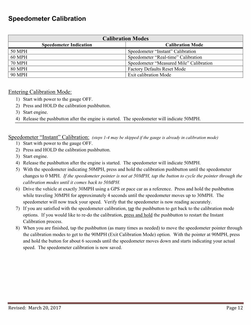
Speedometer Calibration
Calibration Modes
Speedometer Indication Calibration Mode 50 MPH Speedometer “Instant” Calibration 60 MPH Speedometer “Real-time” Calibration 70 MPH Speedometer “Measured Mile” Calibration 80 MPH Factory Defaults Reset Mode 90 MPH Exit calibration Mode
Entering Calibration Mode: 1) Start with power to the gauge OFF. 2) Press and HOLD the calibration pushbutton. 3) Start engine. 4) Release the pushbutton after the engine is started. The speedometer will indicate 50MPH.
Speedometer “Instant” Calibration: (steps 1-4 may be skipped if the gauge is already in calibration mode)
1) Start with power to the gauge OFF. 2) Press and HOLD the calibration pushbutton. 3) Start engine. 4) Release the pushbutton after the engine is started. The speedometer will indicate 50MPH. 5) With the speedometer indicating 50MPH, press and hold the calibration pushbutton until the speedometer
changes to 0 MPH. If the speedometer pointer is not at 50MPH, tap the button to cycle the pointer through the calibration modes until it comes back to 50MPH.
6) Drive the vehicle at exactly 30MPH using a GPS or pace car as a reference. Press and hold the pushbutton while traveling 30MPH for approximately 4 seconds until the speedometer moves up to 30MPH. The speedometer will now track your speed. Verify that the speedometer is now reading accurately.
7) If you are satisfied with the speedometer calibration, tap the pushbutton to get back to the calibration mode options. If you would like to re-do the calibration, press and hold the pushbutton to restart the Instant Calibration process.
8) When you are finished, tap the pushbutton (as many times as needed) to move the speedometer pointer through the calibration modes to get to the 90MPH (Exit Calibration Mode) option. With the pointer at 90MPH, press and hold the button for about 6 seconds until the speedometer moves down and starts indicating your actual speed. The speedometer calibration is now saved.

Revised:March20,2017 Page13
Speedometer “Real-Time” Calibration: (steps 1-4 may be skipped if the gauge is already in calibration mode) 1) Start with power to the gauge OFF. 2) Press and HOLD the calibration pushbutton. 3) Start engine. 4) Release the pushbutton after the engine is started. The speedometer will indicate 50MPH. 5) Tap the calibration pushbutton once to move the speedometer pointer up to 60MPH. If you missed stopping the
pointer at 60MPH, continue to tap the button to cycle the pointer through the calibration modes until it comes back to 60MPH.
6) With the speedometer indicating 60MPH, press and hold the calibration pushbutton until the speedometer changes to 0 MPH.
7) Begin driving a known speed using a GPS or pace vehicle as a reference. 8) Press and hold the pushbutton to slowly change the indicated speed. The first time the button is pressed will
increase the speedometer reading. The next time the button is pressed will decrease the speedometer reading. The speedometer will alternate between increasing and decreasing speed each time the button is pressed and held.
9) Continue to press and hold the pushbutton until the speedometer is indicating the correct speed. 10) Once the correct speed is dialed in on the speedometer, wait 8 seconds without pressing the pushbutton to have
the current calibration saved. If you still need to adjust the speed after this 8 second timeout, press and hold the button to re-enter the “Real Time” calibration mode again.
11) If you are satisfied with the speedometer calibration, tap the pushbutton (as many times as needed) to move the speedometer pointer through the calibration modes to get to the 90MPH (Exit Calibration Mode) option. With the pointer at 90MPH, press and hold the button for about 6 seconds until the speedometer moves down and starts indicating your actual speed. The speedometer calibration is now saved.
Speedometer “Measured Mile” Calibration: (steps 1-4 may be skipped if the gauge is already in calibration mode)
1) Start with power to the gauge OFF. 2) Press and HOLD the calibration pushbutton. 3) Start engine. 4) Release the pushbutton after the engine is started. The speedometer will indicate 50MPH. 5) Tap the calibration pushbutton twice to move the speedometer pointer up to 70MPH. If you missed stopping
the pointer at 70MPH, continue to tap the button to cycle the pointer through the calibration modes until it comes back to 70MPH.
6) With the speedometer indicating 70MPH, press and hold the calibration pushbutton until the speedometer changes to 30 MPH.
7) Begin driving a known measured mile. The speed at which you drive the mile does not matter. 8) At the end of the mile, press and hold the pushbutton until the speedometer moves from 30MPH back up to
70MPH. To get a more accurate calibration, stop at the end of the mile. 9) If you are satisfied with the speedometer calibration, tap the pushbutton (as many times as needed) to move the
speedometer pointer through the calibration modes to get to the 90MPH (Exit Calibration Mode) option. With the pointer at 90MPH, press and hold the button for about 6 seconds until the speedometer moves down and starts indicating your actual speed. The speedometer calibration is now saved.

Revised:March20,2017 Page14
Reset Gauge Calibration to Factory Defaults: (steps 1-4 may be skipped if the gauge is already in calibration mode) 1) Start with power to the gauge OFF. 2) Press and HOLD the calibration pushbutton. 3) Start engine (or just turn the key ON). 4) Release the pushbutton after the engine is started (or the key has been turned ON). The speedometer will
indicate 50MPH. 5) Tap the calibration pushbutton three times to move the speedometer pointer up to 80MPH. If you missed
stopping the pointer at 80MPH, continue to tap the button to cycle the pointer through the calibration modes until it comes back to 80MPH.
6) With the speedometer indicating 80MPH, press and hold the calibration pushbutton until the speedometer changes to 90 MPH. The factory speedometer calibration is now set.
7) With the speedometer pointer at 90MPH, press and hold the button for about 6 seconds until the speedometer pointer moves down to zero.


