Document Identification: Detailed design CII Type number Issue TN 80.242 1 Page : 1 / 90 BELISSIMA Contract No. 19297/05/NL/SFe WP80.242 Detailed design of Compartment II Organization Approval Loop : Issue Date Issue Prepared by (visa): Checked by (visa): Approved by (visa): 10/02/2011 1 H. Elslander, W. Schiettecatte H. De Wever H. De Wever Date : 09/02/2011 Date : 10/02/2011 Date : 10/02/2011 Customer Approval : Approval Date Issue Approved by (visa): 14/02/2011 1 B. Lamaze Distribution List : Company Name Number of copies ESA B. Lamaze 2 + electronic VITO H. De Wever 1 (electronic) UBP G. Dussap 1 (electronic) UAB F. Godia 1 (electronic)
Transcript
Document Identification: Detailed design CII
Type number Issue
TN 80.242 1 Page : 1 / 90
BELISSIMA Contract No. 19297/05/NL/SFe WP80.242 Detailed design of Compartment II
Organization Approval Loop :
Issue Date Issue Prepared by (visa): Checked by (visa): Approved by (visa):
10/02/2011 1
H. Elslander, W. Schiettecatte
H. De Wever
H. De Wever
Date : 09/02/2011 Date : 10/02/2011 Date : 10/02/2011
Customer Approval :
Approval Date Issue Approved by (visa):
14/02/2011 1
B. Lamaze
Distribution List :
Company
Name Number of copies
ESA B. Lamaze 2 + electronic VITO H. De Wever 1 (electronic) UBP G. Dussap 1 (electronic) UAB F. Godia 1 (electronic)
Document Identification: Detailed design CII
Type number Issue
TN 80.242 1 Page : 2 / 90
Change log:
Date Issue Reason of the change Modified paragraphs
9.3 EFFLUENT TANK (VSL2_2200_01)............................................................................................................... 70 9.3.1 Start-up ............................................................................................................................................. 70 9.3.2 Nominal operation ............................................................................................................................. 71 9.3.3 Shut down .......................................................................................................................................... 71
9.4 CLEANING PROCESS ..................................................................................................................................... 71 9.4.1 Cleaning the influent tank .................................................................................................................. 71 9.4.2 Cleaning the photobioreactor ............................................................................................................. 72 9.4.3 Cleaning the effluent tank .................................................................................................................. 73 9.4.4 Cleaning acid/base lines .................................................................................................................... 74 9.4.5 Cleaning the retractable probes ......................................................................................................... 74
9.5 STERILISATION PROCESS .............................................................................................................................. 74 9.5.1 Sterilisation of influent tank ............................................................................................................... 74 9.5.2 Sterilisation of bioreactor .................................................................................................................. 75 9.5.3 Sterilisation of effluent tank................................................................................................................ 76 9.5.4 Sterilisation of acid/base lines ............................................................................................................ 77 9.5.5 Sterilisation of the retractable probes ................................................................................................. 77 9.5.6 Sterilisation of inoculum line .............................................................................................................. 78 9.5.7 Sampling ........................................................................................................................................... 78
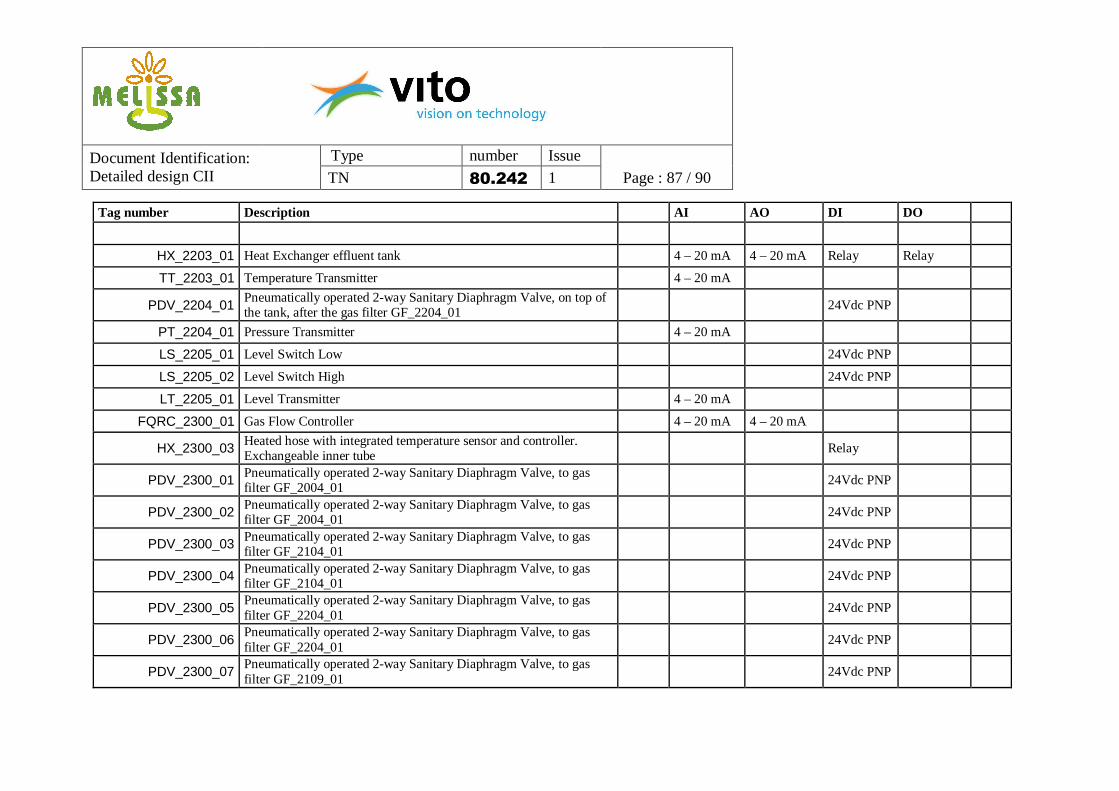
11. PLC I/O LIST ................................................................................................................................................ 81
Document Identification: Detailed design CII
Type number Issue
TN 80.242 1 Page : 5 / 90
1. Scope The MELiSSA loop consists of several compartments, all having a dedicated function. The different process conditions and the intermediate separation techniques are expected to eliminate the major part of the contaminants entering the loop. Within the BELISSIMA contract, a small-scale MELiSSA loop will be constructed to monitor the behaviour of various microcompounds in this model closed loop system. The BELISSIMA loop will consist of compartments I to IVa and should at a later stage be extendible with a higher plant compartment of appropriate size to allow for statistically relevant analysis on the cultivated vegetables. TN80.241 addressed the final loop sizing for the whole BELISSIMA loop and included the detailed design of the Waste Preparation Unit and Compartment I. After approval of TN80.241, it was decided that the availability of a steam sterilizable rather than an autoclavable photoreactor in Compartment II would be crucial for the microcompound study. While commercial autoclavable photoreactors exist with a 100% illuminated volume (preferable for Compartment II operation), this is not the case for steam sterilizable ones. This document thus starts with a brief update of the loop sizing, since a different light/dark ratio of the photoreactor will be used. Analogue to the description of the Waste Preparation Unit and Compartment I in TN80.241, it then provides the detailed design for compartment II. This includes the hardware description, component lists, P&ID’s with different operation modes, the process description, electro-technical data, PLC data and control values.
2. Reference and applicable documents
2.1 Applicable documents AD1 19071/05/NL/CP Memorandum of Understanding between MELiSSA partners
2.2 Reference documents
3. Acronyms CIP Cleaning in Place SIP Steaming in Place VFA Volatile Fatty Acids
Document Identification: Detailed design CII
Type number Issue
TN 80.242 1 Page : 6 / 90
4. Update loop sizing The photoreactor must degrade 15 g VFA/day. This should ideally be achieved through a 100% illuminated reactor set-up, as assumed for the overall loop design in TN80.241. However, such photoreactors are typically not supplied as in situ steam sterilizable equipment. Reducing the illuminated fraction of the photoreactor increases the risk of unstable behavior. Therefore, the ratio of the dark to the illuminated zone should be 20/80 at maximum or the illuminated fraction should be at least 0.8. A lot of sensors have to be mounted on the reactor and several of them must be submerged into the photoreactor liquid phase. This will have to be accommodated through a stainless steel bottom part, which will be a major determining factor for the permanent dark zone by design. It is currently estimated that the required height for this bottom dark zone is 15 cm. Assuming an internal diameter of 15 cm, and considering an illuminated fraction of 0.8, a photobioreactor of 75 cm height would be needed, resulting in a working volume of 13.2 l. In this case, the nominal functioning of the photobioreactor would require an incident light flux q0 of 35-40 W/m². This corresponds to 42% of the productivity maximum which would enable to control the productivity inside the photobioreactor in a better way than e.g. at a larger volume of 18 l. This incident light flux requires about 15 halogen lamps working at 1/3 of their electrical power. The hypothetical nominal residence time would be roughly 26 h with a possible range between 14 and 54 hours.
5. Hardware description Compartment II is a mesophilic photoheterotrophic reactor and will receive in closed loop operation the liquid output of the waste compartment CI. The Rhodospirillum rubrum culture will convert volatile fatty acids (VFA) of low molecular weight. CII will be a cylindrical bioreactor, operating at 30°C. The influent is stored in an influent tank, which is cooled to prevent degradation in the buffer. From this tank, the influent is fed continuously to the illuminated reactor. The outflow is a suspension of biomass in spent liquor and is pumped to the cooled effluent buffer. The set-up for compartment II thus consists roughly of an influent tank, a photobioreactor and an effluent tank. Within this paragraph, the hardware is described, including detailed component lists. Chapter 6 contains an extended P&ID on compartment II.
5.1 Influent tank The influent tank is a stainless steel reactor with a double jacket. The influent tank will receive synthetic medium or effluent from CI, routed over a sanitary liquid filter. This influent is cooled, using a cooler connected to the double jacket. The feed is continuously mixed, using a magnetic coupled stirrer, to obtain a homogeneous cooled medium. The temperature is measured on-line. It is possible to drain the cooling liquid from the double jacket during steam sterilisation of the interior of the buffer. The reactor will be kept at a slight overpressure (100 mbar) using helium. This is controlled based on the foreseen pressure transmitter. Before entering the reactor, helium is
Document Identification: Detailed design CII
Type number Issue
TN 80.242 1 Page : 7 / 90
routed over a sanitary gas filter. A back-pressure valve is added in the entering gas loop to prevent the tank from overpressure. An additional relief valve is added to the tank for emergency protection. A level transmitter indicates the precise liquid height inside the buffer. As an indication and protection of equipment two additional level switches are foreseen (high and low). At the bottom of the tank, connections and valves are added for sampling and drainage of the reactor before cleaning. In case the triverter valve can be mounted close to the tank, no additional bottom tank valve will be needed. A steam sterilisable gear pump will pump the liquid into the photobioreactor, over a sanitary liquid filter. A flow transmitter measures and controls the flow rate. The bypass over the flow transmitter will be opened to guarantee sufficient flow during cleaning and sterilisation. The different hardware items are listed in Table 1.
Document Identification: Detailed design CII
Type number Issue
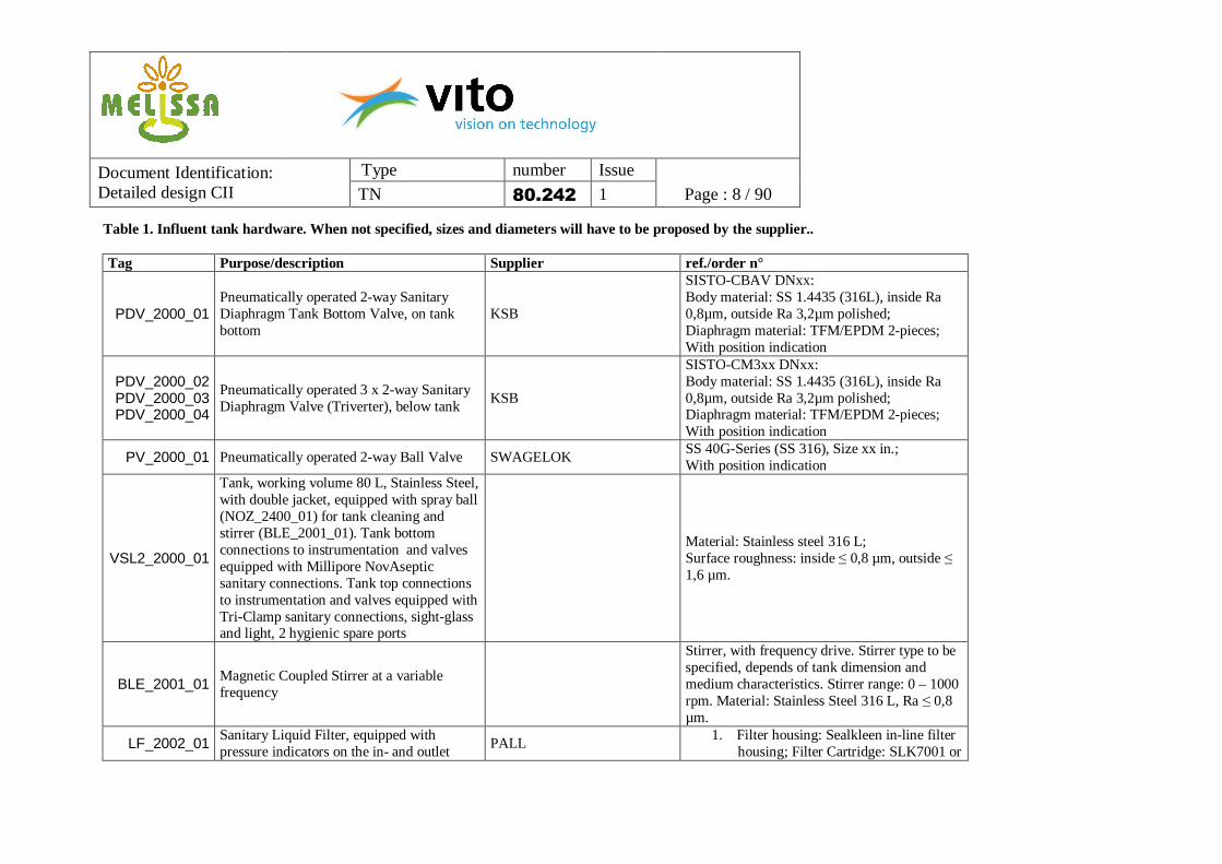
TN 80.242 1 Page : 8 / 90 Table 1. Influent tank hardware. When not specified, sizes and diameters will have to be proposed by the supplier.. Tag Purpose/description Supplier ref./order n°
PDV_2000_01 Pneumatically operated 2-way Sanitary Diaphragm Tank Bottom Valve, on tank bottom
KSB
SISTO-CBAV DNxx: Body material: SS 1.4435 (316L), inside Ra 0,8µm, outside Ra 3,2µm polished; Diaphragm material: TFM/EPDM 2-pieces; With position indication
PDV_2000_02 PDV_2000_03 PDV_2000_04
Pneumatically operated 3 x 2-way Sanitary Diaphragm Valve (Triverter), below tank
KSB
SISTO-CM3xx DNxx: Body material: SS 1.4435 (316L), inside Ra 0,8µm, outside Ra 3,2µm polished; Diaphragm material: TFM/EPDM 2-pieces; With position indication
PV_2000_01 Pneumatically operated 2-way Ball Valve SWAGELOK SS 40G-Series (SS 316), Size xx in.; With position indication
VSL2_2000_01
Tank, working volume 80 L, Stainless Steel, with double jacket, equipped with spray ball (NOZ_2400_01) for tank cleaning and stirrer (BLE_2001_01). Tank bottom connections to instrumentation and valves equipped with Millipore NovAseptic sanitary connections. Tank top connections to instrumentation and valves equipped with Tri-Clamp sanitary connections, sight-glass and light, 2 hygienic spare ports
BLE_2001_01 Magnetic Coupled Stirrer at a variable frequency
Stirrer, with frequency drive. Stirrer type to be specified, depends of tank dimension and medium characteristics. Stirrer range: 0 – 1000 rpm. Material: Stainless Steel 316 L, Ra ≤ 0,8 µm.
LF_2002_01 Sanitary Liquid Filter, equipped with pressure indicators on the in- and outlet
PDV_2002_01 Pneumatically operated 2-way Sanitary Diaphragm Valve, on top of the tank
KSB
SISTO-C DNxx: Body material: SS 1.4435 (316L), inside Ra 0,8µm, outside Ra 3,2µm polished; Diaphragm material: TFM/EPDM 2-pieces; With position indication
PDV_2002_02 Pneumatically operated 2-way Sanitary Diaphragm Valve, zero dead leg, before liquid filter LF_2002_01
KSB
SISTO-C DNxx: Body material: SS 1.4435 (316L), inside Ra 0,8µm, outside Ra 3,2µm polished; Diaphragm material: TFM/EPDM 2-pieces; With position indication
PDV_2002_03 PDV_2002_04 PDV_2002_05
Pneumatically operated 3 x 2-way Sanitary Diaphragm Valve (Triverter), before liquid filter LF_2002_01
KSB
SISTO-CM3xx DNxx: Body material: SS 1.4435 (316L), inside Ra 0,8µm, outside Ra 3,2µm polished; Diaphragm material: TFM/EPDM 2-pieces; With position indication
PV_2002_01 Pneumatically operated 2-way Ball Valve SWAGELOK SS 40G-Series (SS 316), Size xx in.; With position indication
housing; Filter Cartridge: High Flow TETPOR II, sterilizing grade 0,2 µm.
PDV_2004_01 Pneumatically operated 2-way Sanitary Diaphragm Valve, on top of the tank, after the gas filter GF_2004_01
KSB
SISTO-C DNxx: Body material: SS 1.4435 (316L), inside Ra 0,8µm, outside Ra 3,2µm polished; Diaphragm material: TFM/EPDM 2-pieces; With position indication
Document Identification: Detailed design CII
Type number Issue
TN 80.242 1 Page : 11 / 90
PT_2004_01 Pressure Transmitter E+H Cerabar M PMP45,Stainless Steel 316 L, Ra ≤ 0,8 µm, Tri-Clamp hygienic process connection
RV_2004_01 Pressure Relief Valve LESER Type 483
LS_2005_01 Level Switch Low E+H Liquiphant M FTL50(H), Stainless Steel 316 L, Ra ≤ 0,8 µm, Tri-Clamp hygienic process connection
LS_2005_02 Level Switch High E+H Liquiphant M FTL50(H), Stainless Steel 316 L, Ra ≤ 0,8 µm, Tri-Clamp hygienic process connection
LT_2005_01 Level Transmitter E+H Levelflex FMP53, Stainless Steel 316 L, Ra ≤ 0,8 µm, Tri-Clamp hygienic process connection
FT_2006_01 Flow Transmitter, Coriolis mass flow measuring system.
E+H Proline Promass 83A, DN01, Ra ≤ 0,8 µm, Tri-Clamp hygienic process connection
GP_2006_01 Magnetic Drive Gear Pump with steam bypass and speed control, CIP & SIP capability
GATHER Industrie (SUURMOND)
GATHER pump unit MB1 6-19 SIP with SIP bypass diaphragm valve PDV_2006_02 and frequency drive. Flow range: 0,3-6 l/h (7,2-144 l/d). Actual range needed is 5.8-22.6 l/d.
LF_2006_01 Sanitary Liquid Filter, equipped with pressure indicators on the in- and outlet
SISTO-C DNxx: Body material: SS 1.4435 (316L), inside Ra 0,8µm, outside Ra 3,2µm polished; Diaphragm material: TFM/EPDM 2-pieces; With position indication
PDV_2006_03 PDV_2006_04 PDV_2006_05
Pneumatically operated 3 x 2-way Sanitary Diaphragm Valve (Triverter), before liquid filter LF_2006_01
KSB
SISTO-CM3xx DNxx: Body material: SS 1.4435 (316L), inside Ra 0,8µm, outside Ra 3,2µm polished; Diaphragm material: TFM/EPDM 2-pieces; With position indication
PDV_2006_06 PDV_2006_07 PDV_2006_08
Pneumatically operated 3 x 2-way Sanitary Diaphragm Valve (Triverter), after liquid filter LF_2006_01
KSB
SISTO-CM3xx DNxx: Body material: SS 1.4435 (316L), inside Ra 0,8µm, outside Ra 3,2µm polished; Diaphragm material: TFM/EPDM 2-pieces; With position indication
PV_2006_01 Pneumatically operated 2-way Ball Valve SWAGELOK SS 40G-Series (SS 316), Size xx in.; With position indication
PV_2006_02 Pneumatically operated 2-way Ball Valve SWAGELOK SS 40G-Series (SS 316), Size xx in.; With position indication
Document Identification: Detailed design CII
Type number Issue
TN 80.242 1 Page : 13 / 90
5.2 Bioreactor hardware The photobioreactor is an illuminated steam-sterilisable glass/stainless steel reactor with a double jacket. A round stainless steel top and bottom plate will be needed in order to guarantee sufficient space for all required sensors (e.g. retractable pH and biomass probes) and connections (Figure 1). The ratio in permanent dark to illuminated zone should not exceed 20/80, in order to ensure a continuous stable process.
DN 150
DN 25 Ingold
(pH)
NA Connect TC 25,2 ¾”(Sample, Drain)
TC 25,2
TC 25,2
(Base)
DN 25 Ingold(Turbidity)
(Acid)
DN 25 Ingold
(Level Switch)
TC 25,2
(Spare)
Vw= 13,2 LP= 0,1 – 3 bar
TC 77,5 ?
(Stirrer)
DN 25 Ingold
(Level Switch)
(Spare)
TC 25,2 TC 25,2
(Condensor)
(CO2)
(Influent)
(Gas sampling)
TC 25,2
(Pressure)
TC 25,2
(Effluent)
(He/CO2)
TC 25,2
(Temperture)
(Nozzle)
(Spare)
(Spare)
Figure 1. Drawing bioreactor - dimensions
Document Identification: Detailed design CII
Type number Issue
TN 80.242 1 Page : 14 / 90
The reactor will be kept at 30°C by means of the liquid inside the double jacket, routed over a heat exchanger. A sanitary liquid filter is added to the cooling loop in order to reduce biofilm formation inside the double jacket. Cooled influent is added to the reactor. However, due to the heat input from the halogen lamps, cooling will be required. A temperature sensor is added for measurement and control. The sensor will be insulated to ensure that it can be replaced without contamination of the photoreactor content. The pH sensor contains a temperature sensor as well, offering back-up for the control. A drain vessel on the double jacket is foreseen to remove the cooling liquid during sterilisation. A magnetic coupled stirrer is provided in order to maintain a constant temperature inside the reactor, as well as a homogeneously mixed biomass (Rhodospirillum rubrum). For the inoculation of the bioreactor a connection is foreseen in the effluent piping, in order to send the inoculum backwards to the reactor, by means of overpressure, using helium. Influent is fed at the bottom of the reactor, after filtration over a sanitary filter. A pressure indication over the liquid filter is foreseen. Baffles will be needed in the photoreactor to prevent the risk of vortex effects. The pH is measured on-line by a retractable probe. Based on the pH measurement, acid or base are automatically added for pH correction. They are stored in glass bottles and fed with peristaltic pumps over steam sterilisable sanitary liquid filters. The amount dosed will be monitored with balances. The pH will be controlled using sulphuric acid and sodium hydroxide. The reactor will be kept at a slight overpressure (100 mbar) using helium. This is controlled based on the foreseen pressure transmitter in the reactor. Before entering the reactor, helium is sterilised over a sanitary gas filter. A back-pressure valve is added in the entering gas loop to prevent the bioreactor from overpressure. An additional relief valve is added after the condenser for emergency protection. A sanitary gas filter is positioned after the condenser, before the gas sampling connection (included in component list of gas loop, see Table 4). CO2 can be injected at the top or the bottom of the reactor. There will be CO2 present in the off-gas in case that mainly acetate is consumed. However when the feed of the reactor contains butyrate, propionate,… CO2 will rather be consumed. Before being fed to the reactor, CO2 is routed over its specific sanitary gas filter. The top level entry is on the same line as the helium injection. Besides pH, temperature and pressure sensors, a retractable biomass sensor is foreseen in the bottom stainless steel part. A Mettler-Toledo turbidity probe is recommended with a modified wavelength to suit the specific biomass light absorption. This requires a light-emitting diode with a frequency of 950 nm instead of the standard 880 nm. PED certification has to be provided. This certification should not only concern the whole photoreactor, but also all weldings and connections. The bioreactor will be equipped with 15 Decostar IRC halogen lamps (Osram, 12 V, 20 W, 38°) for illumination. The selected lamps radiate around 90% of their electrical power as heat. The total amount of heat generated is therefore close to 300 W. The cool beam characteristic of the lamps
Document Identification: Detailed design CII
Type number Issue
TN 80.242 1 Page : 15 / 90
implies that only half of it is radiated towards the bioreactor. Fans may have to be provided around the reactor to ventilate the heat. The illumination casing should be removable. The electrical circuit needs to be split up in two levels, in order to be able to illuminate only the bottom halve of the reactor during start-up. The light should be dimmable and will be calibrated at start-up, using a manual light intensity measurement device. The biomass-effluent mixture is harvested from the photobioreactor by means of a steam sterilisable gear pump. A flow transmitter is needed to guarantee a correct flow rate. The bypass over the flow transmitter will be used during cleaning and sterilisation. The level in the photoreactor is controlled by the relative ratio between the flows in and out, which are measured by flow transmitters. The suction tube in the reactor will normally be positioned below liquid level, but provides an additional safety to avoid emptying of the photoreactor when the outflow would be higher than the inflow. This does however present a risk of headspace suction into the outlet. As equipment protection a high and low level switch are foreseen in the bioreactor. On the high level switch a foam detection is advisable. Additional ports are available on the top and bottom stainless steel parts of the bioreactor. At the bottom of the reactor a connection and valves are added for sampling and drainage of the reactor before cleaning. In case the triverter valve can be mounted close to the tank, no additional bottom tank valve will be needed. The different hardware items are listed in Table 2.
Document Identification: Detailed design CII
Type number Issue
TN 80.242 1 Page : 16 / 90
Table 2. Bioreactor hardware. When not specified, sizes and diameters will have to be proposed by the constructor. Tag Purpose/description Supplier ref./order n°
LSS_2100_01 Light Supply System with adjustable light intensity / loop and integrated cooling system, 2 separated loops (see notes)
SUURMOND/AUTOCLAVE, DE DIETRICH
Lamps: Halogen spots OSRAM 12V, 20 W BAB 38 °. Cooling: ventilation system
PDV_2100_01 Pneumatically operated 2-way Sanitary Diaphragm Tank Bottom Valve, on reactor bottom (if possible)
KSB
SISTO-CBAV DNxx: Body material: SS 1.4435 (316L), inside Ra 0,8µm, outside Ra 3,2µm polished; Diaphragm material: TFM/EPDM 2-pieces; With position indication
SISTO-CM3xx DNxx: Body material: SS 1.4435 (316L), inside Ra 0,8µm, outside Ra 3,2µm polished; Diaphragm material: TFM/EPDM 2-pieces; With position indication
PV_2100_01 Pneumatically operated 2-way Ball Valve SWAGELOK SS 40G-Series (SS 316), Size xx in.; With position indication
VSL2_2100_01
In-situ sterilizable Combined Stainless/Glass reactor, working volume 13,2 L, PED certified. Equipped with spray ball (NOZ_2400_03) for tank cleaning and stirrer (BLE_2101_01). Reactor bottom connections to instrumentation and other equipment equipped with Ingold or Tri-Clamp sanitary connections. Reactorbottom to tank bottom valve (PDV_2100_01) equipped with Millipore NovAseptic sanitary connection. Tank top connections to instrumentation and valves equipped with
SUURMOND/AUTOCLAVE, DE DIETRICH
Material: Stainless steel 316 L; Surface roughness: inside ≤ 0,8 µm, outside ≤ 1,6 µm. Glass: resistible for SIP, pressure: up to 4 bar
Document Identification: Detailed design CII
Type number Issue
TN 80.242 1 Page : 17 / 90
Tri-Clamp sanitary connections. 3 hygienic spare ports if possible.
BLE_2101_01 Magnetic Coupled Stirrer at a variable frequency, speed in normal operation is 300 – 400 rpm
SUURMOND/AUTOCLAVE, DE DIETRICH
Stirrer, with frequency drive. Stirrer type to be specified, depends of tank dimension and medium characteristics. Stirrer range: 0 – 600 rpm. Material: Stainless Steel 316 L, Ra ≤ 0,8 µm.
HV_2103_01 Hand valve double jacket glass reactor SUURMOND/AUTOCLAVE, DE DIETRICH
To be specified
HV_2103_02 Hand valve double jacket glass reactor SUURMOND/AUTOCLAVE, DE DIETRICH
To be specified
HV_2103_02 Hand valve double jacket glass reactor SUURMOND/AUTOCLAVE, DE DIETRICH
To be specified
H3V_2103_01 Manual operated 3-way Sanitary Ball Valve SVF / VNE Ball Valve, Body material: 316 L, Size xx in., Ra ≤ 0,8 µm, Tri-Clamp hygienic process
H3V_2103_02 Manual operated 3-way Sanitary Ball Valve SVF / VNE Ball Valve, Body material: 316 L, Size xx in., Ra ≤ 0,8 µm, Tri-Clamp hygienic process
LF_2103_01 Liquid Filter AMAFILTER, FILTERMAT Filter cartridge and housing ( Stainless Steel) to be specified by constructor
TT_2103_01 Temperature Transmitter E+H Omnigrad M TR45, Stainless Steel 316 L, Ra ≤ 0,8 µm,Tri-Clamp or Ingold fitting DN 25hygienic process connection
VSSL_2003_01 Tank to collect cooling liquid during steam sterilization, Stainless Steel
filter housing; Filter Cartridge: High Flow TETPOR II, sterilizing grade 0,2 µm.
PDV_2104_01 Pneumatically operated 2-way Sanitary Diaphragm Valve, on top of the reactor, after the gas filter GF_2104_01
KSB
SISTO-C DNxx: Body material: SS 1.4435 (316L), inside Ra 0,8µm, outside Ra 3,2µm polished; Diaphragm material: TFM/EPDM 2-pieces; With position indication
PT_2104_01 Pressure Transmitter E+H Cerabar M PMP45,Stainless Steel 316 L, Ra ≤ 0,8 µm, Tri-Clamp hygienic process connection
RV_2104_01 Pressure Relief Valve LESER Type 483, Stainless Steel 316 L
LS_2105_01 Level Switch Low E+H Liquiphant M FTL50(H), Ra ≤ 0,8 µm, Ingold fitting DN 25 hygiënic process connection
LS_2105_02 Level Switch High, with option “Foam Detection”
E+H Liquiphant M FTL51(H), Ra ≤ 0,8 µm, Ingold fitting DN 25 hygiënic process connection
ATK_2106_01 Glass bottle for inoculum DURAN GROUP GLS 80 Glass bottle, 5 l, with GL 18 screw cap with 4 ports
FT_2106_01 Flow Transmitter, Coriolis mass flow E+H Proline Promass 83A, DN01, Ra ≤ 0,8 µm,
Document Identification: Detailed design CII
Type number Issue
TN 80.242 1 Page : 19 / 90
measuring system. Tri-Clamp hygienic process connection
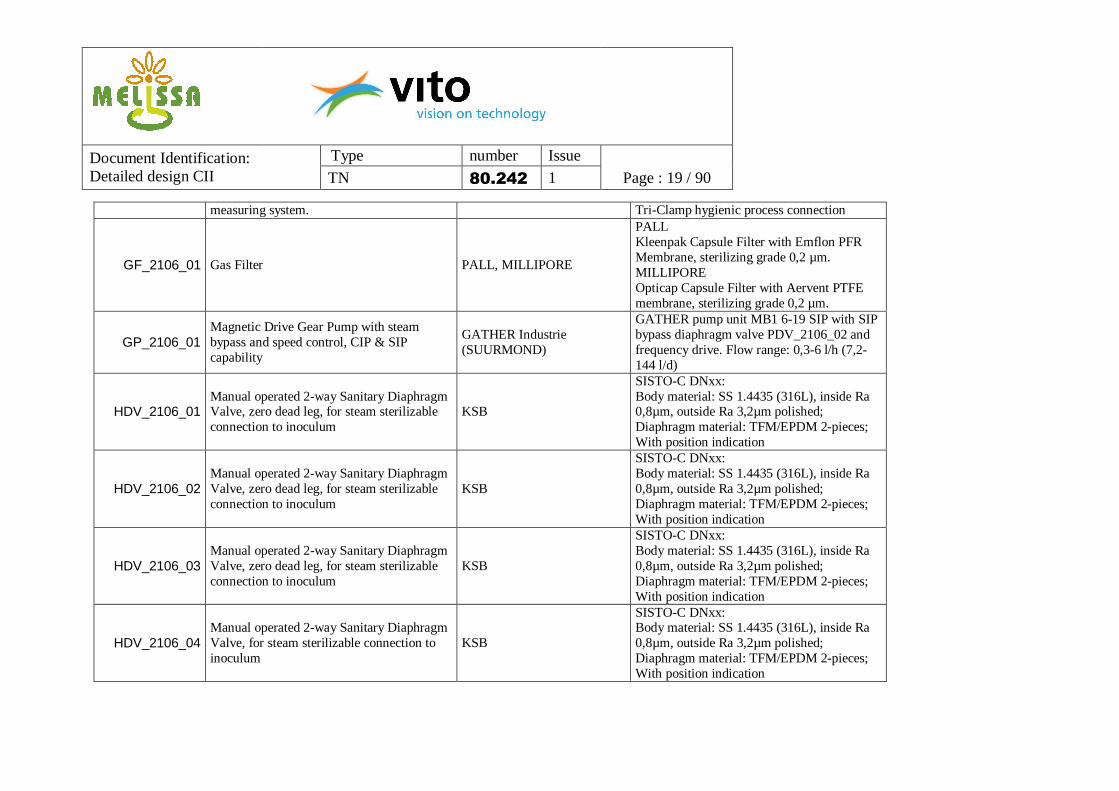
GP_2106_01 Magnetic Drive Gear Pump with steam bypass and speed control, CIP & SIP capability
GATHER Industrie (SUURMOND)
GATHER pump unit MB1 6-19 SIP with SIP bypass diaphragm valve PDV_2106_02 and frequency drive. Flow range: 0,3-6 l/h (7,2-144 l/d)
HDV_2106_01 Manual operated 2-way Sanitary Diaphragm Valve, zero dead leg, for steam sterilizable connection to inoculum
KSB
SISTO-C DNxx: Body material: SS 1.4435 (316L), inside Ra 0,8µm, outside Ra 3,2µm polished; Diaphragm material: TFM/EPDM 2-pieces; With position indication
HDV_2106_02 Manual operated 2-way Sanitary Diaphragm Valve, zero dead leg, for steam sterilizable connection to inoculum
KSB
SISTO-C DNxx: Body material: SS 1.4435 (316L), inside Ra 0,8µm, outside Ra 3,2µm polished; Diaphragm material: TFM/EPDM 2-pieces; With position indication
HDV_2106_03 Manual operated 2-way Sanitary Diaphragm Valve, zero dead leg, for steam sterilizable connection to inoculum
KSB
SISTO-C DNxx: Body material: SS 1.4435 (316L), inside Ra 0,8µm, outside Ra 3,2µm polished; Diaphragm material: TFM/EPDM 2-pieces; With position indication
HDV_2106_04 Manual operated 2-way Sanitary Diaphragm Valve, for steam sterilizable connection to inoculum
KSB
SISTO-C DNxx: Body material: SS 1.4435 (316L), inside Ra 0,8µm, outside Ra 3,2µm polished; Diaphragm material: TFM/EPDM 2-pieces; With position indication
Document Identification: Detailed design CII
Type number Issue
TN 80.242 1 Page : 20 / 90
PDV_2106_01 Pneumatically operated 2-way Sanitary Diaphragm Valve, on top of the reactor
KSB
SISTO-C DNxx: Body material: SS 1.4435 (316L), inside Ra 0,8µm, outside Ra 3,2µm polished; Diaphragm material: TFM/EPDM 2-pieces; With position indication
PDV_2106_02 Pneumatically operated 2-way Sanitary Diaphragm Valve, zero dead leg
KSB
SISTO-C DNxx: Body material: SS 1.4435 (316L), inside Ra 0,8µm, outside Ra 3,2µm polished; Diaphragm material: TFM/EPDM 2-pieces; With position indication
SISTO-C DNxx: Body material: SS 1.4435 (316L), inside Ra 0,8µm, outside Ra 3,2µm polished; Diaphragm material: TFM/EPDM 2-pieces; With position indication
PDV_2106_04 PDV_2106_05 PDV_2106_06
Pneumatically operated 3 x 2-way Sanitary Diaphragm Valve (Triverter), after pump GP_2106_01
KSB
SISTO-CM3xx DNxx: Body material: SS 1.4435 (316L), inside Ra 0,8µm, outside Ra 3,2µm polished; Diaphragm material: TFM/EPDM 2-pieces; With position indication
PDV_2106_07 Pneumatically operated 2-way Sanitary Diaphragm Valve, on top of the reactor
KSB
SISTO-C DNxx: Body material: SS 1.4435 (316L), inside Ra 0,8µm, outside Ra 3,2µm polished; Diaphragm material: TFM/EPDM 2-pieces; With position indication
PV_2106_01 Pneumatically operated 2-way Ball Valve SWAGELOK SS 40G-Series (SS 316), x mm; With position indication
AT_2107_01 pH measurement, pH sensor with automatically retractable sterilizable housing, and position indication
METTLER TOLEDO
Sensor: InPro 3253(with integrated temperature sensor), digital sensor (ISM), length probe: 325 mm Transmitter: M400 / pH 2100 e, in conjunction with ISM sensors.
Document Identification: Detailed design CII
Type number Issue
TN 80.242 1 Page : 21 / 90
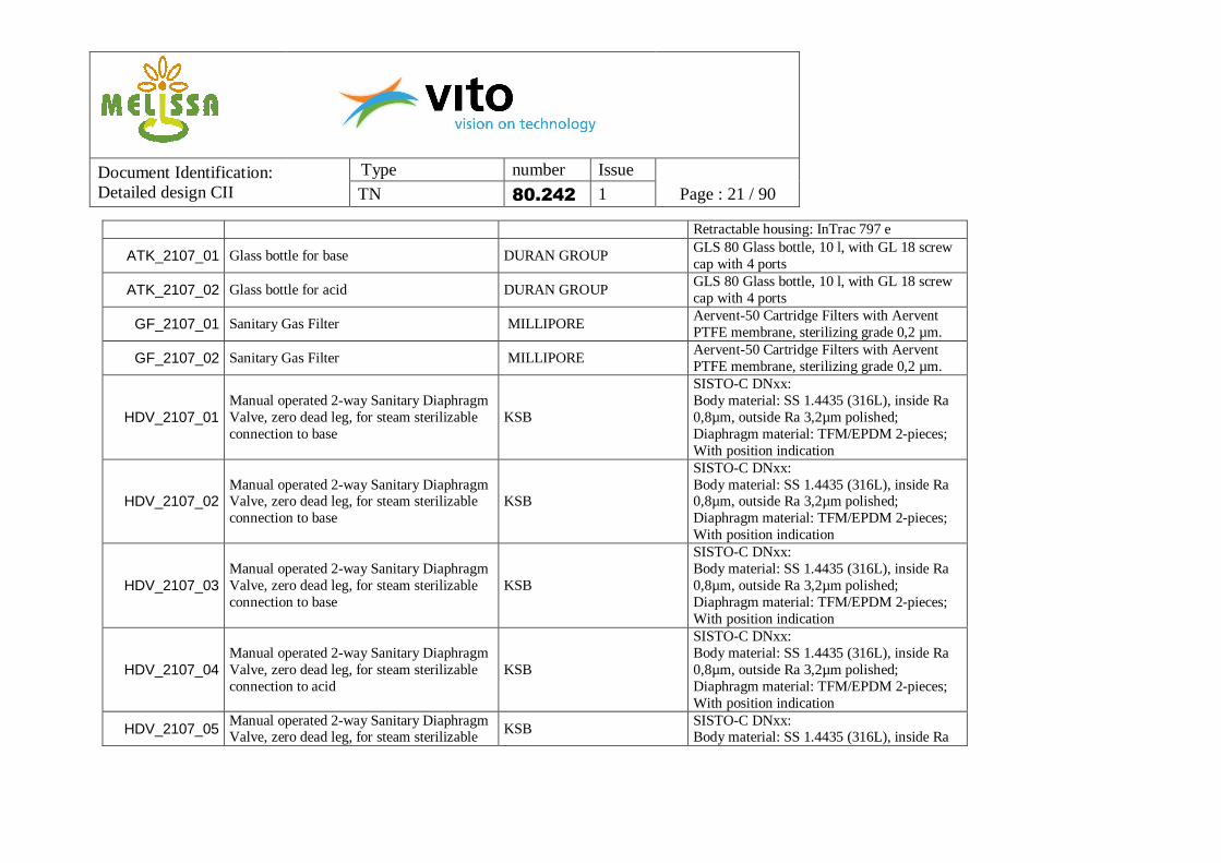
Retractable housing: InTrac 797 e
ATK_2107_01 Glass bottle for base DURAN GROUP GLS 80 Glass bottle, 10 l, with GL 18 screw cap with 4 ports
ATK_2107_02 Glass bottle for acid DURAN GROUP GLS 80 Glass bottle, 10 l, with GL 18 screw cap with 4 ports
GF_2107_01 Sanitary Gas Filter MILLIPORE Aervent-50 Cartridge Filters with Aervent PTFE membrane, sterilizing grade 0,2 µm.
GF_2107_02 Sanitary Gas Filter MILLIPORE Aervent-50 Cartridge Filters with Aervent PTFE membrane, sterilizing grade 0,2 µm.
HDV_2107_01 Manual operated 2-way Sanitary Diaphragm Valve, zero dead leg, for steam sterilizable connection to base
KSB
SISTO-C DNxx: Body material: SS 1.4435 (316L), inside Ra 0,8µm, outside Ra 3,2µm polished; Diaphragm material: TFM/EPDM 2-pieces; With position indication
HDV_2107_02 Manual operated 2-way Sanitary Diaphragm Valve, zero dead leg, for steam sterilizable connection to base
KSB
SISTO-C DNxx: Body material: SS 1.4435 (316L), inside Ra 0,8µm, outside Ra 3,2µm polished; Diaphragm material: TFM/EPDM 2-pieces; With position indication
HDV_2107_03 Manual operated 2-way Sanitary Diaphragm Valve, zero dead leg, for steam sterilizable connection to base
KSB
SISTO-C DNxx: Body material: SS 1.4435 (316L), inside Ra 0,8µm, outside Ra 3,2µm polished; Diaphragm material: TFM/EPDM 2-pieces; With position indication
HDV_2107_04 Manual operated 2-way Sanitary Diaphragm Valve, zero dead leg, for steam sterilizable connection to acid
KSB
SISTO-C DNxx: Body material: SS 1.4435 (316L), inside Ra 0,8µm, outside Ra 3,2µm polished; Diaphragm material: TFM/EPDM 2-pieces; With position indication
HDV_2107_05 Manual operated 2-way Sanitary Diaphragm Valve, zero dead leg, for steam sterilizable KSB
SISTO-C DNxx: Body material: SS 1.4435 (316L), inside Ra
Document Identification: Detailed design CII
Type number Issue
TN 80.242 1 Page : 22 / 90
connection to acid 0,8µm, outside Ra 3,2µm polished; Diaphragm material: TFM/EPDM 2-pieces; With position indication
HDV_2107_06 Manual operated 2-way Sanitary Diaphragm Valve, zero dead leg, for steam sterilizable connection to acid
KSB
SISTO-C DNxx: Body material: SS 1.4435 (316L), inside Ra 0,8µm, outside Ra 3,2µm polished; Diaphragm material: TFM/EPDM 2-pieces; With position indication
HDV_2107_07 Manual operated 2-way Sanitary Diaphragm Valve to pH retractable
KSB
SISTO-C DNxx: Body material: SS 1.4435 (316L), inside Ra 0,8µm, outside Ra 3,2µm polished; Diaphragm material: TFM/EPDM 2-pieces; With position indication
HDV_2107_08 Manual operated 2-way Sanitary Diaphragm Valve to pH retractable
KSB
SISTO-C DNxx: Body material: SS 1.4435 (316L), inside Ra 0,8µm, outside Ra 3,2µm polished; Diaphragm material: TFM/EPDM 2-pieces; With position indication
HDV_2107_09 Manual operated 2-way Sanitary Diaphragm Valve to pH retractable
KSB
SISTO-C DNxx: Body material: SS 1.4435 (316L), inside Ra 0,8µm, outside Ra 3,2µm polished; Diaphragm material: TFM/EPDM 2-pieces; With position indication
HV_2107_01 Manual operated 2-way Ball Valve SWAGELOK SS 40G-Series (SS 316), x mm; With position indication
HV_2107_02 Manual operated 2-way Ball Valve SWAGELOK SS 40G-Series (SS 316), x mm; With position indication
HV_2107_03 Manual operated 2-way Ball Valve SWAGELOK SS 40G-Series (SS 316), x mm; With position indication
HV_2107_04 Manual operated 2-way Ball Valve SWAGELOK SS 40G-Series (SS 316), x mm; With position indication
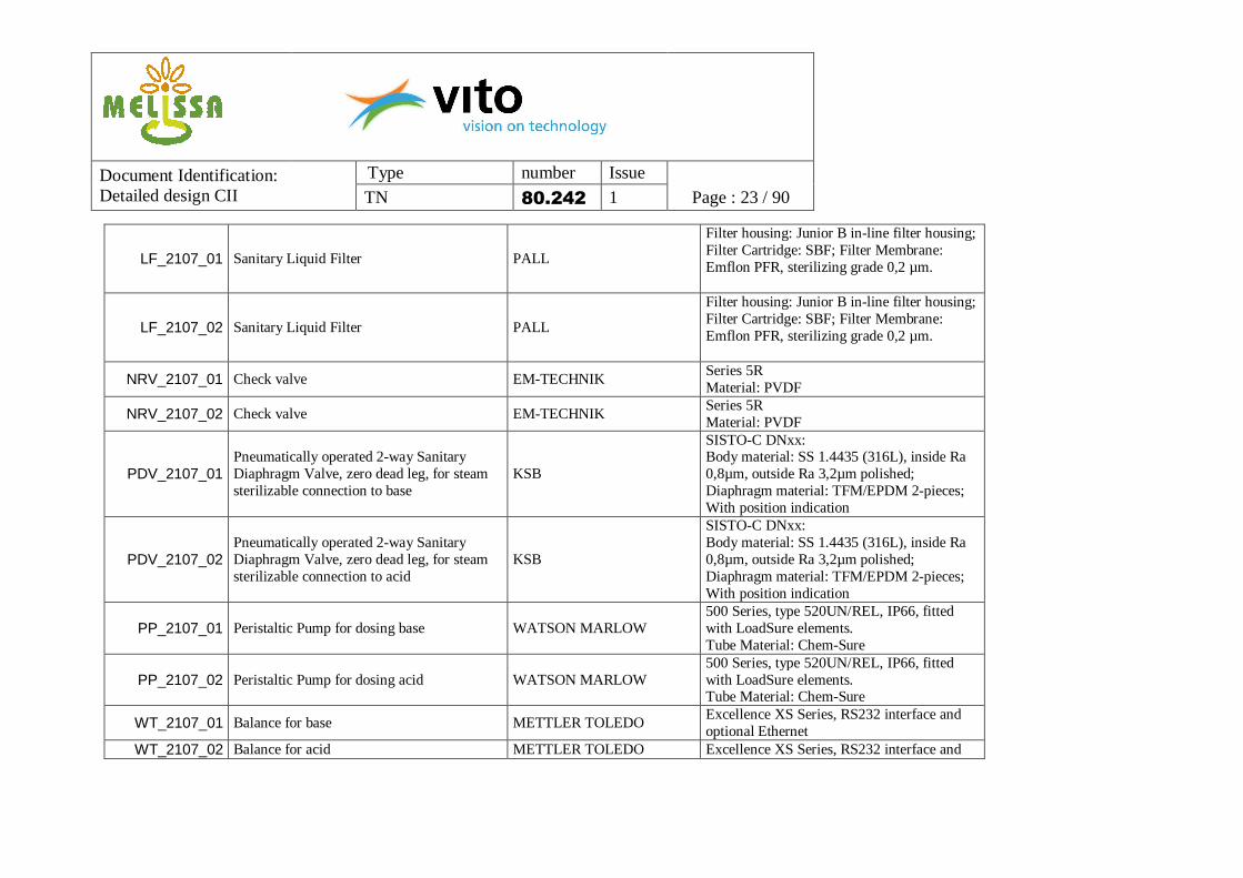
NRV_2107_01 Check valve EM-TECHNIK Series 5R Material: PVDF
NRV_2107_02 Check valve EM-TECHNIK Series 5R Material: PVDF
PDV_2107_01 Pneumatically operated 2-way Sanitary Diaphragm Valve, zero dead leg, for steam sterilizable connection to base
KSB
SISTO-C DNxx: Body material: SS 1.4435 (316L), inside Ra 0,8µm, outside Ra 3,2µm polished; Diaphragm material: TFM/EPDM 2-pieces; With position indication
PDV_2107_02 Pneumatically operated 2-way Sanitary Diaphragm Valve, zero dead leg, for steam sterilizable connection to acid
KSB
SISTO-C DNxx: Body material: SS 1.4435 (316L), inside Ra 0,8µm, outside Ra 3,2µm polished; Diaphragm material: TFM/EPDM 2-pieces; With position indication
PP_2107_01 Peristaltic Pump for dosing base WATSON MARLOW 500 Series, type 520UN/REL, IP66, fitted with LoadSure elements. Tube Material: Chem-Sure
PP_2107_02 Peristaltic Pump for dosing acid WATSON MARLOW 500 Series, type 520UN/REL, IP66, fitted with LoadSure elements. Tube Material: Chem-Sure
WT_2107_01 Balance for base METTLER TOLEDO Excellence XS Series, RS232 interface and optional Ethernet
WT_2107_02 Balance for acid METTLER TOLEDO Excellence XS Series, RS232 interface and
Document Identification: Detailed design CII
Type number Issue
TN 80.242 1 Page : 24 / 90
optional Ethernet
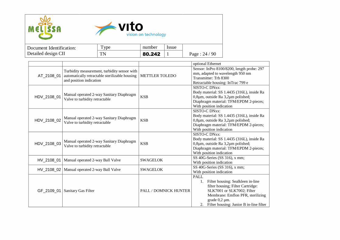
AT_2108_01 Turbidity measurement, turbidity sensor with automatically retractable sterilizable housing and position indication
METTLER TOLEDO
Sensor: InPro 8100/8200, length probe: 297 mm, adapted to wavelength 950 nm Transmitter: Trb 8300 Retractable housing: InTrac 799 e
HDV_2108_01 Manual operated 2-way Sanitary Diaphragm Valve to turbidity retractable
KSB
SISTO-C DNxx: Body material: SS 1.4435 (316L), inside Ra 0,8µm, outside Ra 3,2µm polished; Diaphragm material: TFM/EPDM 2-pieces; With position indication
SISTO-C DNxx: Body material: SS 1.4435 (316L), inside Ra 0,8µm, outside Ra 3,2µm polished; Diaphragm material: TFM/EPDM 2-pieces; With position indication
HDV_2108_03 Manual operated 2-way Sanitary Diaphragm Valve to turbidity retractable
KSB
SISTO-C DNxx: Body material: SS 1.4435 (316L), inside Ra 0,8µm, outside Ra 3,2µm polished; Diaphragm material: TFM/EPDM 2-pieces; With position indication
HV_2108_01 Manual operated 2-way Ball Valve SWAGELOK SS 40G-Series (SS 316), x mm; With position indication
HV_2108_02 Manual operated 2-way Ball Valve SWAGELOK SS 40G-Series (SS 316), x mm; With position indication
GF_2109_01 Sanitary Gas Filter PALL / DOMNICK HUNTER
filter housing; Filter Cartridge: High Flow TETPOR II, sterilizing grade 0,2 µm.
HDV_2109_01 Manual operated 2-way Sanitary Diaphragm Valve, after the gas filter GF_2109_01
KSB
SISTO-C DNxx: Body material: SS 1.4435 (316L), inside Ra 0,8µm, outside Ra 3,2µm polished; Diaphragm material: TFM/EPDM 2-pieces; With position indication
HDV_2109_02 Manual operated 2-way Sanitary Diaphragm Valve, after the gas filter GF_2109_01
KSB
SISTO-C DNxx: Body material: SS 1.4435 (316L), inside Ra 0,8µm, outside Ra 3,2µm polished; Diaphragm material: TFM/EPDM 2-pieces; With position indication
PDV_2109_01 Pneumatically operated 2-way Sanitary Diaphragm Valve, after the gas filter GF_2109_01
KSB
SISTO-C DNxx: Body material: SS 1.4435 (316L), inside Ra 0,8µm, outside Ra 3,2µm polished; Diaphragm material: TFM/EPDM 2-pieces; With position indication
PDV_2109_02 Pneumatically operated 2-way Sanitary Diaphragm Valve, after the gas filter GF_2109_01
KSB
SISTO-C DNxx: Body material: SS 1.4435 (316L), inside Ra 0,8µm, outside Ra 3,2µm polished; Diaphragm material: TFM/EPDM 2-pieces; With position indication
Document Identification: Detailed design CII
Type number Issue
TN 80.242 1 Page : 26 / 90
5.3 Effluent tank From the bioreactor, the biomass/effluent mixture is pumped towards the effluent tank. Similar to the influent tank, this is a stainless steel reactor with a double jacket. The effluent is cooled, using a cooler connected to the double jacket. The biomass/effluent mixture is continuously mixed, using a magnetic coupled stirrer, to obtain a homogeneous cooled medium. The temperature is measured on-line. It is possible to drain the cooling liquid from the double-jacket during sterilisation of the interior of the buffer with steam. The reactor will be kept at a slight overpressure (100 mbar) using helium. This is controlled based on the foreseen pressure transmitter. Before entering the reactor, the helium is routed over a sanitary gas filter. A back-pressure valve is added in the entering gas loop to prevent the tank from overpressure. An additional relief valve is added to the tank for emergency protection. A level transmitter indicates the precise liquid height inside the buffer. As an indication and protection of equipment two additional level switches are foreseen (high and low). At the bottom of the tank connections and valves are added for sampling or transfer of the tank content to compartment III, or drainage of the reactor before cleaning. In case the triverter can be set close to the tank, no additional bottom tank valve will be needed. The different hardware items are listed in Table 3.
Document Identification: Detailed design CII
Type number Issue
TN 80.242 1 Page : 27 / 90
Table 3. Effluent tank hardware. When not specified, sizes and diameters will have to be proposed by the constructor. Tag Purpose/description Supplier ref./order n°
PDV_2200_01 Pneumatically operated 2-way Sanitary Diaphragm Tank Bottom Valve, on tank bottom
KSB
SISTO-CBAV DNxx: Body material: SS 1.4435 (316L), inside Ra 0,8µm, outside Ra 3,2µm polished; Diaphragm material: TFM/EPDM 2-pieces; With position indication
PDV_2200_02 PDV_2200_03 PDV_2200_04
Pneumatically operated 3 x 2-way Sanitary Diaphragm Valve (Triverter), below tank
KSB
SISTO-CM3xx DNxx: Body material: SS 1.4435 (316L), inside Ra 0,8µm, outside Ra 3,2µm polished; Diaphragm material: TFM/EPDM 2-pieces; With position indication
PV_2200_01 Pneumatically operated 2-way Ball Valve SWAGELOK SS 40G-Series (SS 316), Size xx in.; With position indication
VSL2_2200_01
Tank 80 L, Stainless Steel, with double jacket, equipped with spray ball (NOZ_2400_02) for tank cleaning and stirrer (BLE_2201_01). Tank bottom connections to instrumentation and valves equipped with Millipore NovAseptic sanitary connections. Tank top connections to instrumentation and valves equipped with Tri-Clamp sanitary connections, sight-glass and light, 2 hygienic spare ports
BLE_2201_01 Magnetic Coupled Stirrer at a variable frequency
Stirrer, with frequency drive. Stirrer type to be specified, depends of tank dimension and medium characteristics. Stirrer range: 0 – 1000 rpm. Material: Stainless Steel 316 L, Ra ≤ 0,8 µm.
1. Filter Housing: Demi HSI in-line filter housing; Filter Cartridge: High Flow TETPOR II, sterilizing grade 0,2 µm.
PDV_2204_01 Pneumatically operated 2-way Sanitary Diaphragm Valve, on top of the tank, after the gas filter GF_2204_01
KSB
SISTO-C DNxx: Body material: SS 1.4435 (316L), inside Ra 0,8µm, outside Ra 3,2µm polished; Diaphragm material: TFM/EPDM 2-pieces; With position indication
PT_2204_01 Pressure Transmitter E+H Cerabar M PMP45, Stainless Steel 316 L,Ra ≤ 0,8 µm, Tri-Clamp hygienic process connection
RV_2204_01 Pressure Relief Valve LESER Type 483, Stainless Steel 316 L
LS_2205_01 Level Switch Low E+H Liquiphant M FTL50(H), Stainless Steel 316L, Ra ≤ 0,8 µm, Tri-Clamp hygienic process connection
LS_2205_02 Level Switch High E+H Liquiphant M FTL50(H), Stainless Steel, Ra ≤ 0,8 µm, Tri-Clamp hygienic process connection
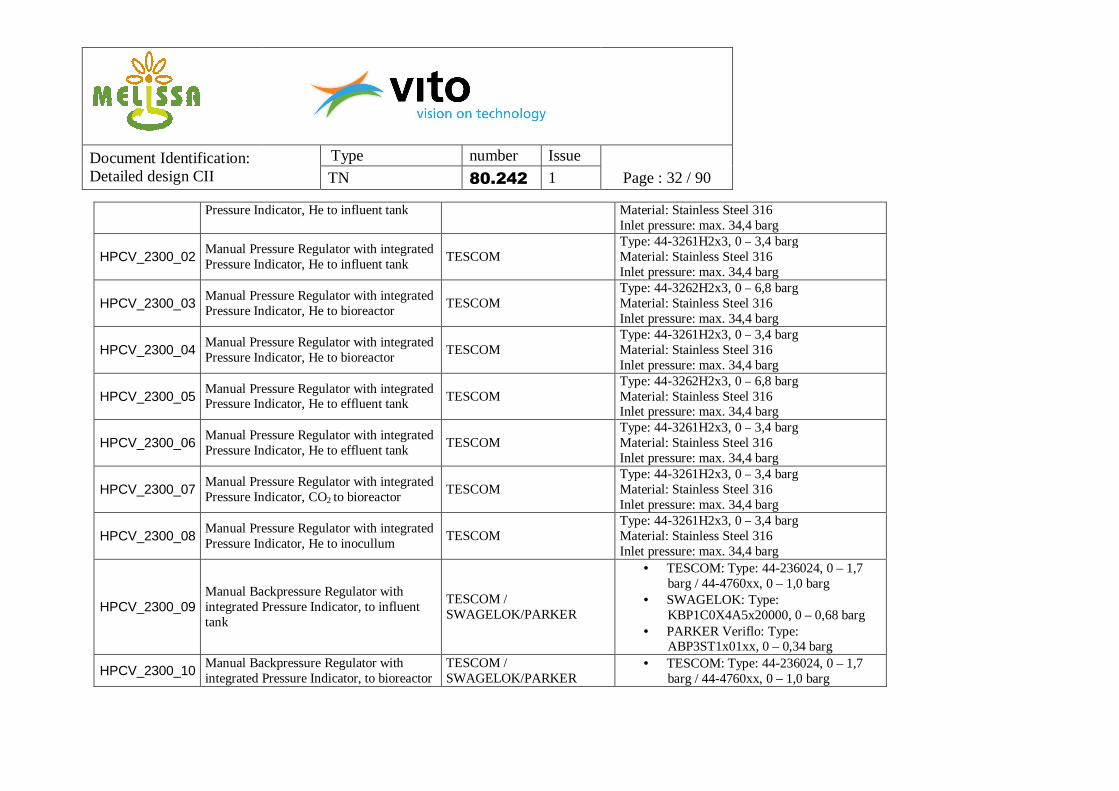
5.4 Gas loop The gas loop consists of the CO2 and He circuits. As described in paragraph 5.2 (Bioreactor), CO2 is routed over its dedicated sanitary gas filter before entering top or bottom of the photobioreactor. Injection will be needed depending on the specific composition of the influent. A gas flow controller is foreseen for correct dosing. Helium will be used during different operation steps. During normal operation it can be injected in the headspaces of both storage tanks and the bioreactor, in order to maintain a constant overpressure. This way, the risk of contamination is further reduced. All three tanks have their dedicated He-inlet area, split over two manual pressure regulators: a first one set at 1,5 bar for use at normal operation and for draining the volume and all piping before and after CIP, the second one set at 3,5 bar, providing He for drying all parts after SIP. Before entering the specific part of the Compartment, helium is routed over a sanitary gas filter. Excess gas is eliminated through the foreseen pressure regulators at the end of the gas lines, before the gas filters. All three tank volumes (influent, effluent and bioreactor) are equipped as well with pressure relieve valves as emergency protection to overpressure. The different hardware items are listed in Table 4.
Document Identification: Detailed design CII
Type number Issue
TN 80.242 1 Page : 31 / 90
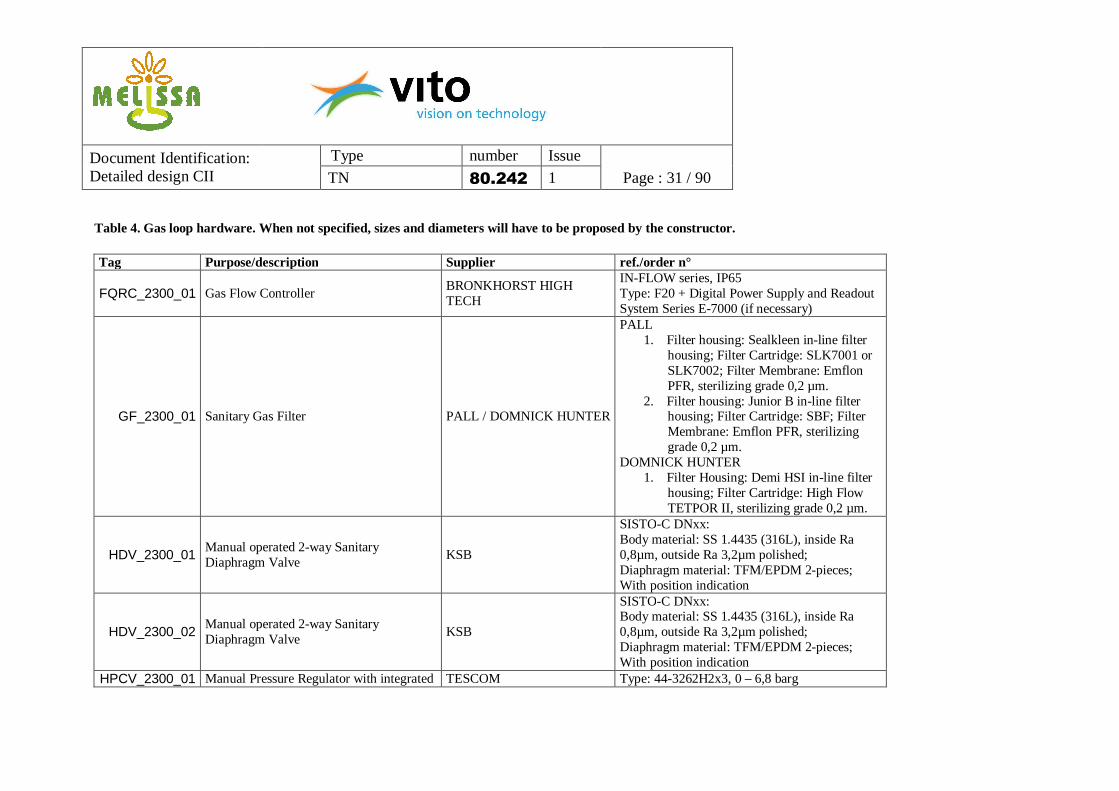
Table 4. Gas loop hardware. When not specified, sizes and diameters will have to be proposed by the constructor. Tag Purpose/description Supplier ref./order n°
FQRC_2300_01 Gas Flow Controller BRONKHORST HIGH TECH
IN-FLOW series, IP65 Type: F20 + Digital Power Supply and Readout System Series E-7000 (if necessary)
GF_2300_01 Sanitary Gas Filter PALL / DOMNICK HUNTER
SISTO-C DNxx: Body material: SS 1.4435 (316L), inside Ra 0,8µm, outside Ra 3,2µm polished; Diaphragm material: TFM/EPDM 2-pieces; With position indication
SISTO-C DNxx: Body material: SS 1.4435 (316L), inside Ra 0,8µm, outside Ra 3,2µm polished; Diaphragm material: TFM/EPDM 2-pieces; With position indication
HX_2300_01 Condensor SUURMOND/AUTOCLAVE, DE DIETRICH
To be specified by constructor
HX_2300_02 Heat exchanger, using cooling liquid from the available infrastructure
HV_2300_01 Hand valve condensor SUURMOND/AUTOCLAVE, DE DIETRICH
To be specified by constructor
HV_2300_02 Hand valve condensor SUURMOND/AUTOCLAVE, DE DIETRICH
To be specified by constructor
HV_2300_03 Hand valve condensor SUURMOND/AUTOCLAVE, DE DIETRICH
To be specified by constructor
HV_2300_04 Manual operated 2-way Ball Valve, gas sample valve bioreactor
SWAGELOK SS 40G-Series (SS 316), Size xx in.
HV_2300_05 Manual operated 2-way Ball Valve, to gas filter GF_2106_01
SWAGELOK SS 40G-Series (SS 316), Size xx in.
PDV_2300_01 Pneumatically operated 2-way Sanitary Diaphragm Valve, to gas filter GF_2004_01
KSB
SISTO-C DNxx: Body material: SS 1.4435 (316L), inside Ra 0,8µm, outside Ra 3,2µm polished; Diaphragm material: TFM/EPDM 2-pieces; With position indication
PDV_2300_02 Pneumatically operated 2-way Sanitary Diaphragm Valve, to gas filter
KSB SISTO-C DNxx: Body material: SS 1.4435 (316L), inside Ra
Document Identification: Detailed design CII
Type number Issue
TN 80.242 1 Page : 34 / 90
GF_2004_01 0,8µm, outside Ra 3,2µm polished; Diaphragm material: TFM/EPDM 2-pieces; With position indication
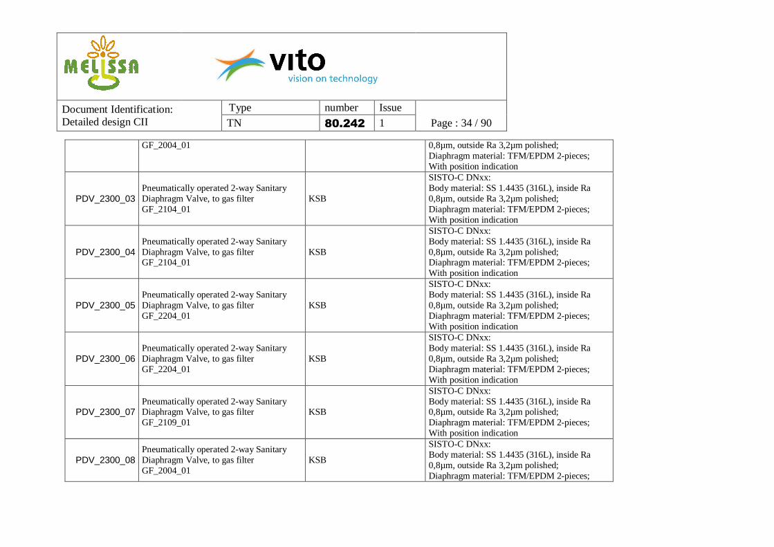
PDV_2300_03 Pneumatically operated 2-way Sanitary Diaphragm Valve, to gas filter GF_2104_01
KSB
SISTO-C DNxx: Body material: SS 1.4435 (316L), inside Ra 0,8µm, outside Ra 3,2µm polished; Diaphragm material: TFM/EPDM 2-pieces; With position indication
PDV_2300_04 Pneumatically operated 2-way Sanitary Diaphragm Valve, to gas filter GF_2104_01
KSB
SISTO-C DNxx: Body material: SS 1.4435 (316L), inside Ra 0,8µm, outside Ra 3,2µm polished; Diaphragm material: TFM/EPDM 2-pieces; With position indication
PDV_2300_05 Pneumatically operated 2-way Sanitary Diaphragm Valve, to gas filter GF_2204_01
KSB
SISTO-C DNxx: Body material: SS 1.4435 (316L), inside Ra 0,8µm, outside Ra 3,2µm polished; Diaphragm material: TFM/EPDM 2-pieces; With position indication
PDV_2300_06 Pneumatically operated 2-way Sanitary Diaphragm Valve, to gas filter GF_2204_01
KSB
SISTO-C DNxx: Body material: SS 1.4435 (316L), inside Ra 0,8µm, outside Ra 3,2µm polished; Diaphragm material: TFM/EPDM 2-pieces; With position indication
PDV_2300_07 Pneumatically operated 2-way Sanitary Diaphragm Valve, to gas filter GF_2109_01
KSB
SISTO-C DNxx: Body material: SS 1.4435 (316L), inside Ra 0,8µm, outside Ra 3,2µm polished; Diaphragm material: TFM/EPDM 2-pieces; With position indication
PDV_2300_08 Pneumatically operated 2-way Sanitary Diaphragm Valve, to gas filter GF_2004_01
KSB
SISTO-C DNxx: Body material: SS 1.4435 (316L), inside Ra 0,8µm, outside Ra 3,2µm polished; Diaphragm material: TFM/EPDM 2-pieces;
Document Identification: Detailed design CII
Type number Issue
TN 80.242 1 Page : 35 / 90
With position indication
PDV_2300_09 Pneumatically operated 2-way Sanitary Diaphragm Valve, to gas filter GF_2104_01
KSB
SISTO-C DNxx: Body material: SS 1.4435 (316L), inside Ra 0,8µm, outside Ra 3,2µm polished; Diaphragm material: TFM/EPDM 2-pieces; With position indication
PDV_2300_10 Pneumatically operated 2-way Sanitary Diaphragm Valve, to gas filter GF_2204_01
KSB
SISTO-C DNxx: Body material: SS 1.4435 (316L), inside Ra 0,8µm, outside Ra 3,2µm polished; Diaphragm material: TFM/EPDM 2-pieces; With position indication
PDV_2300_11 Pneumatically operated 2-way Sanitary Diaphragm Valve, to gas filter GF_2109_01
KSB
SISTO-C DNxx: Body material: SS 1.4435 (316L), inside Ra 0,8µm, outside Ra 3,2µm polished; Diaphragm material: TFM/EPDM 2-pieces; With position indication
PV_2300_01 Pneumatically operated 2-way Ball Valve SWAGELOK SS 40G-Series (SS 316), Size xx in.; With position indication
PV_2300_02 Pneumatically operated 2-way Ball Valve SWAGELOK SS 40G-Series (SS 316), Size xx in.; With position indication
PV_2300_03 Pneumatically operated 2-way Ball Valve SWAGELOK SS 40G-Series (SS 316), Size xx in.; With position indication
Document Identification: Detailed design CII
Type number Issue
TN 80.242 1 Page : 36 / 90
5.5 Cleaning in Place (CIP) All parts of the installation where liquid flows, can be cleaned when needed. Cleaning solution can be added to the influent tank circuit, the bioreactor and the effluent tank and its piping. The cleaning will be semi-automated. Prior to cleaning, piping and tanks will be drained and purged using helium at 1.5 bar. Drains are foreseen at different locations to optimise this process. The cleaning solution can then be sent, for all three volumes separately, through different routes. It should be possible to clean the influent and effluent tanks separately from the bioreactor. For the influent tank, firstly, cleaning solution can be routed, for instance, only through the connecting piping between Compartment I (or the preparation vessel) and Compartment II. The solution can be either drained, if too dirty, or recycled back to a separate mobile CIP-unit. One step further will be to clean the inlet piping, over the sanitary liquid filter, towards the influent tank. This way, the influent tank can be filled as well with cleaning solution. A recycle of the solution is foreseen at the bottom of the tank. An improved cleaning of the influent tank can be obtained by sending the cleaning solution directly through the spray ball. As a last step, cleaning solution can further be routed subsequently over the influent pump, between influent tank and bioreactor, and the sanitary liquid filter prior to recycling. For the bioreactor, cleaning solution can be routed either backwards through the harvesting pipe or through the spray ball. The cleaning liquid can then be either sent backwards through the remaining (unclean) influent piping or through the recycle line at the bottom of the reactor. When closing the connections towards the bioreactor, the cleaning solution can as well be routed through the effluent piping. This way, the effluent piping and pump can be cleaned. After the pump, the cleaning solution can be recycled towards the CIP unit. For the effluent tank, cleaning solution can only be injected through the spray ball. After cleaning, the solution can be drained and recycled at the bottom of the tank. The connections between the acid and base storage bottles and the bioreactor can be cleaned as well. This needs to be done after renewal of a bottle. Both retractable probes on the stainless steel bottom plate of the bioreactor can be cleaned as well. This needs to be done whenever the probe has been detached from the reactor and needs to be re-entered. Further details on CIP can be found in the different operation mode schemes and the process description (see 9). A mobile CIP unit will form part of the compartment II delivery.
Document Identification: Detailed design CII
Type number Issue
TN 80.242 1 Page : 37 / 90
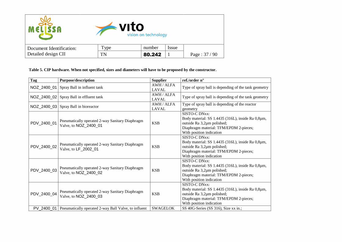
Table 5. CIP hardware. When not specified, sizes and diameters will have to be proposed by the constructor. Tag Purpose/description Supplier ref./order n°
NOZ_2400_01 Spray Ball in influent tank AWH / ALFA LAVAL
Type of spray ball is depending of the tank geometry
NOZ_2400_02 Spray Ball in effluent tank AWH / ALFA LAVAL
Type of spray ball is depending of the tank geometry
NOZ_2400_03 Spray Ball in bioreactor AWH / ALFA LAVAL
Type of spray ball is depending of the reactor geometry
PDV_2400_01 Pneumatically operated 2-way Sanitary Diaphragm Valve, to NOZ_2400_01
KSB
SISTO-C DNxx: Body material: SS 1.4435 (316L), inside Ra 0,8µm, outside Ra 3,2µm polished; Diaphragm material: TFM/EPDM 2-pieces; With position indication
PDV_2400_02 Pneumatically operated 2-way Sanitary Diaphragm Valve, to LF_2002_01
KSB
SISTO-C DNxx: Body material: SS 1.4435 (316L), inside Ra 0,8µm, outside Ra 3,2µm polished; Diaphragm material: TFM/EPDM 2-pieces; With position indication
PDV_2400_03 Pneumatically operated 2-way Sanitary Diaphragm Valve, to NOZ_2400_02
KSB
SISTO-C DNxx: Body material: SS 1.4435 (316L), inside Ra 0,8µm, outside Ra 3,2µm polished; Diaphragm material: TFM/EPDM 2-pieces; With position indication
PDV_2400_04 Pneumatically operated 2-way Sanitary Diaphragm Valve, to NOZ_2400_03
KSB
SISTO-C DNxx: Body material: SS 1.4435 (316L), inside Ra 0,8µm, outside Ra 3,2µm polished; Diaphragm material: TFM/EPDM 2-pieces; With position indication
PV_2400_01 Pneumatically operated 2-way Ball Valve, to influent SWAGELOK SS 40G-Series (SS 316), Size xx in.;
Document Identification: Detailed design CII
Type number Issue
TN 80.242 1 Page : 38 / 90
tank With position indication
PV_2400_02 Pneumatically operated 2-way Ball Valve, to effluent tank
SWAGELOK SS 40G-Series (SS 316), Size xx in.; With position indication
PV_2400_03 Pneumatically operated 2-way Ball Valve, to bioreactor
SWAGELOK SS 40G-Series (SS 316), Size xx in.; With position indication
SWAGELOK SS 40G-Series (SS 316), Size xx in.; With position indication
Mobile CIP unit: • Mobile compact sanitary design for single
use (freshly prepared CIP media); • Consisting of stirred tank for preparation of
cleaning solution, volume, required flows and pressures to be defined by constructor;
• CIP solution recovery system; • Easy to connect to the process unit • Material 316 L, surface roughness: inside ≤
0,8 µm, outside ≤ 1,6 µm; • Two control modes (manual and automatic); • Different operation possibilities (time,
temperature, volume, …) • Temperature range: 20-70°C • Minimal energy consumption
To be proposed by constructor
To be defined by constructor
Document Identification: Detailed design CII
Type number Issue
TN 80.242 1 Page : 39 / 90
5.6 Sterilisation in Place (SIP) To maintain sterility, SIP will be needed and will be implemented after CIP. The final design and lay-out should enable to perform the steaming adequately. An adequate temperature should be reached without any damage to e.g. filters. The different SIP hardware items are listed in Table 6. Points of attention are the following:
- Steam traps o Steam traps should be of the thermodynamic type o Steam traps should not come in contact with dirty product: first a rinse through side-
valves is applied o A temperature measurement is connected to each steam trap
- Valves o All valves in the steam line should be membrane valves o Zero dead leg valves are required o Overpressure valves (e.g. effluent tank) should be of a sanitary type with bellow o Valves should be positioned at an angle of 23-26° for complete outflow
- Steaming o Steam sterilization starts from 1 point, and goes in 1 direction, in antenna-like
approach o First step in SIP: dewatering of steam o All piping should have a slope of 1 cm/m to allow easy outflow of condensate o Cross-sterilization is provided between different parts of the set-up and for
connection to previous/next compartment - Sensors should be mounted at a H < 3D to avoid dead zones
Further details on SIP can be found in the different operation mode schemes and the process description (see 9).
Document Identification: Detailed design CII
Type number Issue
TN 80.242 1 Page : 40 / 90
Table 6. SIP hardware. When not specified, sizes and diameters will have to be proposed by the constructor. Tag Purpose/description Supplier ref./order n°
HDV_2500_01 Manual operated 2-way Sanitary Diaphragm Valve, zero dead leg, in base dosing line
KSB
SISTO-C DNxx: Body material: SS 1.4435 (316L), inside Ra 0,8µm, outside Ra 3,2µm polished; Diaphragm material: TFM/EPDM 2-pieces; With position indication
HDV_2500_02 Manual operated 2-way Sanitary Diaphragm Valve, zero dead leg, in acid dosing line
KSB
SISTO-C DNxx: Body material: SS 1.4435 (316L), inside Ra 0,8µm, outside Ra 3,2µm polished; Diaphragm material: TFM/EPDM 2-pieces; With position indication
HDV_2500_03 Manual operated 2-way Sanitary Diaphragm Valve, zero dead leg, connected to retractable for pH sensor AT_2107_01
KSB
SISTO-C DNxx: Body material: SS 1.4435 (316L), inside Ra 0,8µm, outside Ra 3,2µm polished; Diaphragm material: TFM/EPDM 2-pieces; With position indication
HDV_2500_04 Manual operated 2-way Sanitary Diaphragm Valve, zero dead leg, connected to retractable for turbidity sensor AT_2108_01
KSB
SISTO-C DNxx: Body material: SS 1.4435 (316L), inside Ra 0,8µm, outside Ra 3,2µm polished; Diaphragm material: TFM/EPDM 2-pieces; With position indication
HV_2500_01 Manual operated 2-way Ball Valve SWAGELOK SS 60T-Series (SS 316), Size xx in.; HV_2500_02 Manual operated 2-way Ball Valve SWAGELOK SS 60T-Series (SS 316), Size xx in.; HV_2500_03 Manual operated 2-way Ball Valve SWAGELOK SS 60T-Series (SS 316), Size xx in.;
PDV_2500_01 Pneumatically operated 2-way Sanitary Diaphragm Valve, before gas filter GF_2004_01
KSB
SISTO-C DNxx: Body material: SS 1.4435 (316L), inside Ra 0,8µm, outside Ra 3,2µm polished; Diaphragm material: TFM/EPDM 2-pieces;
Document Identification: Detailed design CII
Type number Issue
TN 80.242 1 Page : 41 / 90
With position indication
PDV_2500_02 Pneumatically operated 2-way Sanitary Diaphragm Valve, after gas filter GF_2004_01
KSB
SISTO-C DNxx: Body material: SS 1.4435 (316L), inside Ra 0,8µm, outside Ra 3,2µm polished; Diaphragm material: TFM/EPDM 2-pieces; With position indication
PDV_2500_03 Pneumatically operated 2-way Sanitary Diaphragm Valve, before gas filter GF_2104_01
KSB
SISTO-C DNxx: Body material: SS 1.4435 (316L), inside Ra 0,8µm, outside Ra 3,2µm polished; Diaphragm material: TFM/EPDM 2-pieces; With position indication
PDV_2500_04 Pneumatically operated 2-way Sanitary Diaphragm Valve, after gas filter GF_2104_01
KSB
SISTO-C DNxx: Body material: SS 1.4435 (316L), inside Ra 0,8µm, outside Ra 3,2µm polished; Diaphragm material: TFM/EPDM 2-pieces; With position indication
PDV_2500_05 Pneumatically operated 2-way Sanitary Diaphragm Valve, before gas filter GF_2204_01
KSB
SISTO-C DNxx: Body material: SS 1.4435 (316L), inside Ra 0,8µm, outside Ra 3,2µm polished; Diaphragm material: TFM/EPDM 2-pieces; With position indication
PDV_2500_06 Pneumatically operated 2-way Sanitary Diaphragm Valve, after gas filter GF_2204_01
KSB
SISTO-C DNxx: Body material: SS 1.4435 (316L), inside Ra 0,8µm, outside Ra 3,2µm polished; Diaphragm material: TFM/EPDM 2-pieces; With position indication
PDV_2500_07 Pneumatically operated 2-way Sanitary Diaphragm Valve, before gas filter GF_2109_01
KSB
SISTO-C DNxx: Body material: SS 1.4435 (316L), inside Ra 0,8µm, outside Ra 3,2µm polished; Diaphragm material: TFM/EPDM 2-pieces; With position indication
Document Identification: Detailed design CII
Type number Issue
TN 80.242 1 Page : 42 / 90
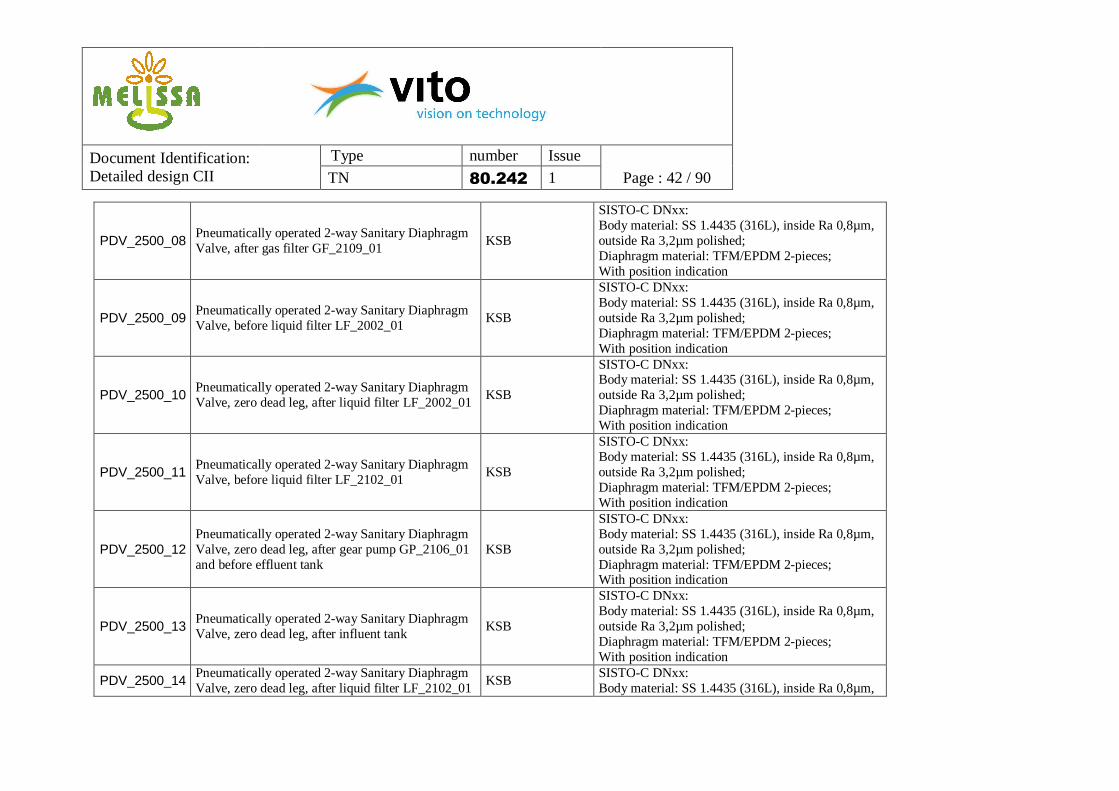
PDV_2500_08 Pneumatically operated 2-way Sanitary Diaphragm Valve, after gas filter GF_2109_01
KSB
SISTO-C DNxx: Body material: SS 1.4435 (316L), inside Ra 0,8µm, outside Ra 3,2µm polished; Diaphragm material: TFM/EPDM 2-pieces; With position indication
SISTO-C DNxx: Body material: SS 1.4435 (316L), inside Ra 0,8µm, outside Ra 3,2µm polished; Diaphragm material: TFM/EPDM 2-pieces; With position indication
PDV_2500_10 Pneumatically operated 2-way Sanitary Diaphragm Valve, zero dead leg, after liquid filter LF_2002_01
KSB
SISTO-C DNxx: Body material: SS 1.4435 (316L), inside Ra 0,8µm, outside Ra 3,2µm polished; Diaphragm material: TFM/EPDM 2-pieces; With position indication
SISTO-C DNxx: Body material: SS 1.4435 (316L), inside Ra 0,8µm, outside Ra 3,2µm polished; Diaphragm material: TFM/EPDM 2-pieces; With position indication
PDV_2500_12 Pneumatically operated 2-way Sanitary Diaphragm Valve, zero dead leg, after gear pump GP_2106_01 and before effluent tank
KSB
SISTO-C DNxx: Body material: SS 1.4435 (316L), inside Ra 0,8µm, outside Ra 3,2µm polished; Diaphragm material: TFM/EPDM 2-pieces; With position indication
PDV_2500_13 Pneumatically operated 2-way Sanitary Diaphragm Valve, zero dead leg, after influent tank
KSB
SISTO-C DNxx: Body material: SS 1.4435 (316L), inside Ra 0,8µm, outside Ra 3,2µm polished; Diaphragm material: TFM/EPDM 2-pieces; With position indication
PDV_2500_14 Pneumatically operated 2-way Sanitary Diaphragm Valve, zero dead leg, after liquid filter LF_2102_01
KSB SISTO-C DNxx: Body material: SS 1.4435 (316L), inside Ra 0,8µm,
Document Identification: Detailed design CII
Type number Issue
TN 80.242 1 Page : 43 / 90
outside Ra 3,2µm polished; Diaphragm material: TFM/EPDM 2-pieces; With position indication
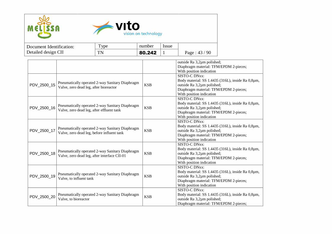
PDV_2500_15 Pneumatically operated 2-way Sanitary Diaphragm Valve, zero dead leg, after bioreactor
KSB
SISTO-C DNxx: Body material: SS 1.4435 (316L), inside Ra 0,8µm, outside Ra 3,2µm polished; Diaphragm material: TFM/EPDM 2-pieces; With position indication
PDV_2500_16 Pneumatically operated 2-way Sanitary Diaphragm Valve, zero dead leg, after effluent tank
KSB
SISTO-C DNxx: Body material: SS 1.4435 (316L), inside Ra 0,8µm, outside Ra 3,2µm polished; Diaphragm material: TFM/EPDM 2-pieces; With position indication
PDV_2500_17 Pneumatically operated 2-way Sanitary Diaphragm Valve, zero dead leg, before influent tank
KSB
SISTO-C DNxx: Body material: SS 1.4435 (316L), inside Ra 0,8µm, outside Ra 3,2µm polished; Diaphragm material: TFM/EPDM 2-pieces; With position indication
PDV_2500_18 Pneumatically operated 2-way Sanitary Diaphragm Valve, zero dead leg, after interface CII-01
KSB
SISTO-C DNxx: Body material: SS 1.4435 (316L), inside Ra 0,8µm, outside Ra 3,2µm polished; Diaphragm material: TFM/EPDM 2-pieces; With position indication
PDV_2500_19 Pneumatically operated 2-way Sanitary Diaphragm Valve, to influent tank
KSB
SISTO-C DNxx: Body material: SS 1.4435 (316L), inside Ra 0,8µm, outside Ra 3,2µm polished; Diaphragm material: TFM/EPDM 2-pieces; With position indication
PDV_2500_20 Pneumatically operated 2-way Sanitary Diaphragm Valve, to bioreactor
KSB
SISTO-C DNxx: Body material: SS 1.4435 (316L), inside Ra 0,8µm, outside Ra 3,2µm polished; Diaphragm material: TFM/EPDM 2-pieces;
Document Identification: Detailed design CII
Type number Issue
TN 80.242 1 Page : 44 / 90
With position indication
PDV_2500_21 Pneumatically operated 2-way Sanitary Diaphragm Valve, to effluent tank
KSB
SISTO-C DNxx: Body material: SS 1.4435 (316L), inside Ra 0,8µm, outside Ra 3,2µm polished; Diaphragm material: TFM/EPDM 2-pieces; With position indication
PDV_2500_22 Pneumatically operated 2-way Sanitary Diaphragm Valve, zero dead leg, before pump GP_2006_01
KSB
SISTO-C DNxx: Body material: SS 1.4435 (316L), inside Ra 0,8µm, outside Ra 3,2µm polished; Diaphragm material: TFM/EPDM 2-pieces; With position indication
PDV_2500_23 Pneumatically operated 2-way Sanitary Diaphragm Valve, after gas filter GF_2300_01
KSB
SISTO-C DNxx: Body material: SS 1.4435 (316L), inside Ra 0,8µm, outside Ra 3,2µm polished; Diaphragm material: TFM/EPDM 2-pieces; With position indication
PDV_2500_24 Pneumatically operated 2-way Sanitary Diaphragm Valve, zero dead leg, before flow transmitter FT_2006_01
KSB
SISTO-C DNxx: Body material: SS 1.4435 (316L), inside Ra 0,8µm, outside Ra 3,2µm polished; Diaphragm material: TFM/EPDM 2-pieces; With position indication
PDV_2500_25 Pneumatically operated 2-way Sanitary Diaphragm Valve, zero dead leg, after flow transmitter FT_2006_01
KSB
SISTO-C DNxx: Body material: SS 1.4435 (316L), inside Ra 0,8µm, outside Ra 3,2µm polished; Diaphragm material: TFM/EPDM 2-pieces; With position indication
PDV_2500_26 Pneumatically operated 2-way Sanitary Diaphragm Valve, zero dead leg, before flow transmitter FT_2106_01
KSB
SISTO-C DNxx: Body material: SS 1.4435 (316L), inside Ra 0,8µm, outside Ra 3,2µm polished; Diaphragm material: TFM/EPDM 2-pieces; With position indication
Document Identification: Detailed design CII
Type number Issue
TN 80.242 1 Page : 45 / 90
PDV_2500_27 Pneumatically operated 2-way Sanitary Diaphragm Valve, zero dead leg, after flow transmitter FT_2106_01
KSB
SISTO-C DNxx: Body material: SS 1.4435 (316L), inside Ra 0,8µm, outside Ra 3,2µm polished; Diaphragm material: TFM/EPDM 2-pieces; With position indication
PV_2500_01 Pneumatically operated 2-way Ball Valve, to gas filter GF_2004_01
SWAGELOK SS 60T-Series (SS 316), Size xx in.; With position indication
PV_2500_02 Pneumatically operated 2-way Ball Valve, to gas filter GF_2104_01
SWAGELOK SS 60T-Series (SS 316), Size xx in.; With position indication
PV_2500_03 Pneumatically operated 2-way Ball Valve, to gas filter GF_2204_01
SWAGELOK SS 60T-Series (SS 316), Size xx in.; With position indication
PV_2500_04 Pneumatically operated 2-way Ball Valve, to gas filter GF_2109_01
SWAGELOK SS 60T-Series (SS 316), Size xx in.; With position indication
SF_2500_01 Balanced Pressure Thermostatic Steam Trap SPIRAX SARCO MST21, Stainless Steel, Size xx in. SF_2500_02 Balanced Pressure Thermostatic Steam Trap SPIRAX SARCO MST21, Stainless Steel, Size xx in. SF_2500_03 Balanced Pressure Thermostatic Steam Trap SPIRAX SARCO MST21, Stainless Steel, Size xx in. SF_2500_04 Balanced Pressure Thermostatic Steam Trap SPIRAX SARCO MST21, Stainless Steel, Size xx in. SF_2500_05 Balanced Pressure Thermostatic Steam Trap SPIRAX SARCO MST21, Stainless Steel, Size xx in. SF_2500_06 Balanced Pressure Thermostatic Steam Trap SPIRAX SARCO MST21, Stainless Steel, Size xx in. SF_2500_07 Balanced Pressure Thermostatic Steam Trap SPIRAX SARCO MST21, Stainless Steel, Size xx in. SF_2500_08 Balanced Pressure Thermostatic Steam Trap SPIRAX SARCO MST21, Stainless Steel, Size xx in. SF_2500_09 Balanced Pressure Thermostatic Steam Trap SPIRAX SARCO MST21, Stainless Steel, Size xx in. SF_2500_10 Balanced Pressure Thermostatic Steam Trap SPIRAX SARCO MST21, Stainless Steel, Size xx in. SF_2500_11 Balanced Pressure Thermostatic Steam Trap SPIRAX SARCO MST21, Stainless Steel, Size xx in. SF_2500_12 Balanced Pressure Thermostatic Steam Trap SPIRAX SARCO MST21, Stainless Steel, Size xx in. SF_2500_13 Balanced Pressure Thermostatic Steam Trap SPIRAX SARCO MST21, Stainless Steel, Size xx in. SF_2500_14 Balanced Pressure Thermostatic Steam Trap SPIRAX SARCO MST21, Stainless Steel, Size xx in. SF_2500_15 Balanced Pressure Thermostatic Steam Trap SPIRAX SARCO MST21, Stainless Steel, Size xx in. SF_2500_16 Balanced Pressure Thermostatic Steam Trap SPIRAX SARCO MST21, Stainless Steel, Size xx in. SF_2500_17 Balanced Pressure Thermostatic Steam Trap SPIRAX SARCO MST21, Stainless Steel, Size xx in.
Document Identification: Detailed design CII
Type number Issue
TN 80.242 1 Page : 46 / 90
SF_2500_18 Balanced Pressure Thermostatic Steam Trap SPIRAX SARCO MST21, Stainless Steel, Size xx in. SF_2500_19 Balanced Pressure Thermostatic Steam Trap SPIRAX SARCO MST21, Stainless Steel, Size xx in. SF_2500_20 Balanced Pressure Thermostatic Steam Trap SPIRAX SARCO MST21, Stainless Steel, Size xx in. SF_2500_21 Balanced Pressure Thermostatic Steam Trap SPIRAX SARCO MST21, Stainless Steel, Size xx in. SF_2500_22 Balanced Pressure Thermostatic Steam Trap SPIRAX SARCO MST21, Stainless Steel, Size xx in. SF_2500_23 Balanced Pressure Thermostatic Steam Trap SPIRAX SARCO MST21, Stainless Steel, Size xx in. SF_2500_24 Balanced Pressure Thermostatic Steam Trap SPIRAX SARCO MST21, Stainless Steel, Size xx in. SF_2500_25 Balanced Pressure Thermostatic Steam Trap SPIRAX SARCO MST21, Stainless Steel, Size xx in.
TT_2500_01 Temperature Transmitter E+H Easytemp 470P, Stainless Steel 316 L, Ra ≤ 0,8 µm, Tri-Clamp hygienic process connection, length of the probe to be specified
TT_2500_02 Temperature Transmitter E+H Easytemp 470P, Stainless Steel 316 L, Ra ≤ 0,8 µm, Tri-Clamp hygienic process connection, length of the probe to be specified
TT_2500_03 Temperature Transmitter E+H Easytemp 470P, Stainless Steel 316 L, Ra ≤ 0,8 µm, Tri-Clamp hygienic process connection, length of the probe to be specified
TT_2500_04 Temperature Transmitter E+H Easytemp 470P, Stainless Steel 316 L, Ra ≤ 0,8 µm, Tri-Clamp hygienic process connection, length of the probe to be specified
TT_2500_05 Temperature Transmitter E+H Easytemp 470P, Stainless Steel 316 L, Ra ≤ 0,8 µm, Tri-Clamp hygienic process connection, length of the probe to be specified
TT_2500_06 Temperature Transmitter E+H Easytemp 470P, Stainless Steel 316 L, Ra ≤ 0,8 µm, Tri-Clamp hygienic process connection, length of the probe to be specified
TT_2500_07 Temperature Transmitter E+H Easytemp 470P, Stainless Steel 316 L, Ra ≤ 0,8 µm, Tri-Clamp hygienic process connection, length of the probe to be specified
TT_2500_08 Temperature Transmitter E+H Easytemp 470P, Stainless Steel 316 L, Ra ≤ 0,8 µm, Tri-Clamp hygienic process connection, length of
Document Identification: Detailed design CII
Type number Issue
TN 80.242 1 Page : 47 / 90
the probe to be specified
TT_2500_09 Temperature Transmitter E+H Easytemp 470P, Stainless Steel 316 L, Ra ≤ 0,8 µm, Tri-Clamp hygienic process connection, length of the probe to be specified
TT_2500_10 Temperature Transmitter E+H Easytemp 470P, Stainless Steel 316 L, Ra ≤ 0,8 µm, Tri-Clamp hygienic process connection, length of the probe to be specified
TT_2500_11 Temperature Transmitter E+H Easytemp 470P, Stainless Steel 316 L, Ra ≤ 0,8 µm, Tri-Clamp hygienic process connection, length of the probe to be specified
TT_2500_12 Temperature Transmitter E+H Easytemp 470P, Stainless Steel 316 L, Ra ≤ 0,8 µm, Tri-Clamp hygienic process connection, length of the probe to be specified
TT_2500_13 Temperature Transmitter E+H Easytemp 470P, Stainless Steel 316 L, Ra ≤ 0,8 µm, Tri-Clamp hygienic process connection, length of the probe to be specified
TT_2500_14 Temperature Transmitter E+H Easytemp 470P, Stainless Steel 316 L, Ra ≤ 0,8 µm, Tri-Clamp hygienic process connection, length of the probe to be specified
TT_2500_15 Temperature Transmitter E+H Easytemp 470P, Stainless Steel 316 L, Ra ≤ 0,8 µm, Tri-Clamp hygienic process connection, length of the probe to be specified
TT_2500_16 Temperature Transmitter E+H Easytemp 470P, Stainless Steel 316 L, Ra ≤ 0,8 µm, Tri-Clamp hygienic process connection, length of the probe to be specified
TT_2500_17 Temperature Transmitter E+H Easytemp 470P, Stainless Steel 316 L, Ra ≤ 0,8 µm, Tri-Clamp hygienic process connection, length of the probe to be specified
TT_2500_18 Temperature Transmitter E+H Easytemp 470P, Stainless Steel 316 L, Ra ≤ 0,8 µm, Tri-Clamp hygienic process connection, length of the probe to be specified
Document Identification: Detailed design CII
Type number Issue
TN 80.242 1 Page : 48 / 90
TT_2500_19 Temperature Transmitter E+H Easytemp 470P, Stainless Steel 316 L, Ra ≤ 0,8 µm, Tri-Clamp hygienic process connection, length of the probe to be specified
TT_2500_20 Temperature Transmitter E+H Easytemp 470P, Stainless Steel 316 L, Ra ≤ 0,8 µm, Tri-Clamp hygienic process connection, length of the probe to be specified
TT_2500_21 Temperature Transmitter E+H Easytemp 470P, Stainless Steel 316 L, Ra ≤ 0,8 µm, Tri-Clamp hygienic process connection, length of the probe to be specified
TT_2500_22 Temperature Transmitter E+H Easytemp 470P, Stainless Steel 316 L, Ra ≤ 0,8 µm, Tri-Clamp hygienic process connection, length of the probe to be specified
TT_2500_23 Temperature Transmitter E+H Easytemp 470P, Stainless Steel 316 L, Ra ≤ 0,8 µm, Tri-Clamp hygienic process connection, length of the probe to be specified
TT_2500_24 Temperature Transmitter E+H Easytemp 470P, Stainless Steel 316 L, Ra ≤ 0,8 µm, Tri-Clamp hygienic process connection, length of the probe to be specified
TT_2500_25 Temperature Transmitter E+H Easytemp 470P, Stainless Steel 316 L, Ra ≤ 0,8 µm, Tri-Clamp hygienic process connection, length of the probe to be specified
Document Identification: Detailed design CII
Type number Issue
TN 80.242 1 Page : 49 / 90
6. P&ID Table 7 provides an overview of the different loops in the system, translated in the used tag numbering.
Document Identification: Detailed design CII
Type number Issue
TN 80.242 1 Page : 50 / 90
The general P&ID is shown in
ATK_2107_01
VSL2_2000_01
VSL2_2100-01
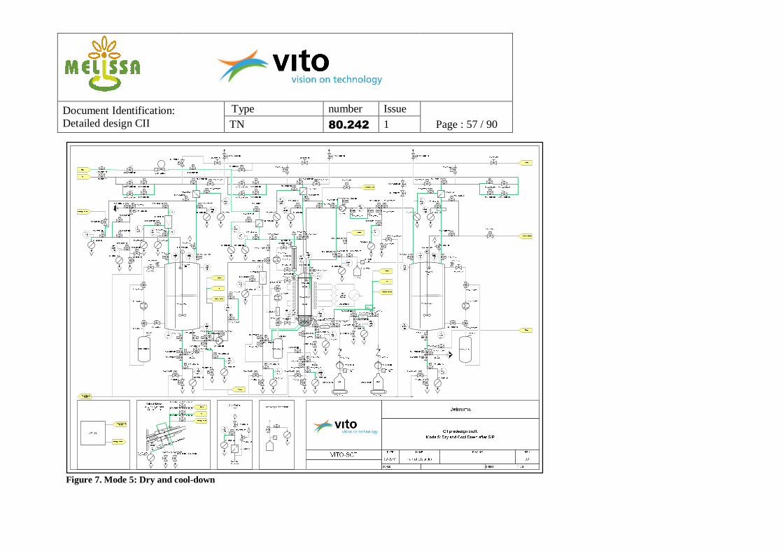
Belissima
CII predesign draft
VITO-SCTDATE NAME DWG NO REV
07/02/11 Helmut Elslander 3.4
SCALE SHEET 1 OF 1
VSL2_2200_01
M
BLE_2001_01
M
BLE_2201_01
HV_2003_02
HV_2003_01
HX_2003_01
HV_2203_02
HV_2203_01
HX_2203_01
TT_
2003_01
TT_
2203_01
He
CO2
Steam
12 CI I0
PT_2004_01
LF_2002_01
SF_2500_09 SF_2500_10
HDV_2300_01
PDV_2500_09 P
PDV_2500_10P
GF_2004_01
PDV_2500_02P
SF_2500_02
LT_2005_01
LS_2005_02
LS_2005_01
RV_2004_01
PDV_2000_01
PDV_2000_02
PDV_2000_03
PDV_2000_04
P
PDV_2002_02 P
PDV_2500_19
P
PV_2000_01
PDV_2006_01
PDV_2500_13P
SF_2500_01
PDV_2500_01P
SF_2500_13
Bio
AT_2108_01
LS_
2105_01
Light
SupplySystem
LSS_2100_01
PDV_2100_01
PDV_2100_02
PDV_2100_03
PDV_2100_04P
PV_2100_01
PDV_2500_15P
SF_2500_15
GP_2006_01
LF_2006_01
SF_2500_11
PV_2006_02SF_2500_14
PDV_2500_14P
LT_
2205_01
PT_2204_01
LS_2205_01
LS_2205_02
RV_2204_01
PDV_2500_06
P
GF_2204_01
SF_2500_06SF_2500_05
PDV_2500_05 P
PDV_2200_01
PDV_2200_02
PDV_2200_03
PDV_2200_04P
PDV_2500_16P
PV_2200_01SF_2500_16
PDV_2006_02
PDV_2106_04
P
PDV_2106_05
P
PDV_2106_06
FT_2106_01
PV_2106_01SF_2500_12
PDV_2500_12 P
CII
PDV_2106_03
HX_2300_01
HX_2103_01
HV_2103_02
HV_2103_01
HV_2300_02
HV_2300_01
RV_2104_01
HDV_2300_02
HPCV_2300_02
HPCV_2300_01 PDV_2300_01
P
PDV_2300_02
P
HPCV_2300_06
HPCV_2300_05PDV_2300_05
P
PDV_2300_06
P
HPCV_2300_04
HPCV_2300_03 PDV_2300_03
P
PDV_2300_04
PGF_2104_01
PDV_2500_04
P
SF_2500_04SF_2500_03
PDV_2500_03 P
HPCV_2300_07 PDV_2300_07
P
HV_2500_03
PDV_2300_10 P
PV_2500_03PV_2500_02
PDV_2300_09PPDV_2300_08P
PV_2500_01HV_2500_02HV_2500_01
GF_2109_01
PDV_2500_08
P
PDV_2500_07
P
PDV_2300_11
P
SF_2500_07 SF_2500_08
PDV_2104_01
PDV_2004_01PDV_2002_01
HDV_2109_01
HDV_2109_02
PDV_2109_01
P
PDV_2106_01
PPV_2500_04
WT_2107_02
ATK_2107_02
GF_2107_02
PP_2107_02
Acid
WT_2107_01
GF_2107_01
PP_2107_01
Base
HDV_2107_05
HDV_2107_02
NRV_2107_02 NRV_2107_01
PPV_2300_02
PPV_2300_01
PPV_2300_03
HPCV_2300_09 HPCV_2300_10 HPCV_2300_11
TT_2500
_13
TT_2500
_14
TT_2500_15
TT_2500
_16
TT_
2500_11
TT_
2500_08
TT_2500
_07
TT_2500_02
TT_
2500_01
TT_2500_04
TT_
2500_03
TT_2500_12
TT_
2500_06
TT_
2500_05
NOZ_2400_01
NOZ_2400_02
Cleaning Solution
PDV_2500_17
P
PDV_2400_01
P
SF_2500_17
PV_2400_01
Cl eaning Soluti on
PDV_2400_03P
P
PV_2400_02
PPV_2400_07
PPV_2400_04
PPV_2400_06
Retour Cleani ng
Solution
TT_2500
_09 TT_2500_10
TT_2500_17
LF_2107_01
LF_2107_02
Condensor
PT_2104
_01
PDV_2109_02
GP_2106_01
PDV_2204_01
PDV_2106_07
PDV_2002_03PPDV_2002_04 P
PDV_2002_05
PV_2002_01SF_2500_18
PDV_2500_18
P
PDV_2400_02
P
TT_2500_18
NOZ_2400_03
Cleaning Solution
PDV_2400_04P
P
PV_2400_03
TT_2500_19
PDV_2106_02
P
TT_
2103_01
M
BLE_2101_01
Gas Vent
VSSL_2003_01
H3V_2003_01
H3V_2003_02
HV_2003_03
HV_2300_03
H3V_2203_02
H3V_2203_01
HV_2203_03
CIP-Unit
Retour Cleani ng
Solution
Cleaning Solution
PDV_2500_20P
PDV_2500_21P
FQRC_2300_01
PPV_2400_05
LS_2105
_02
P PV_2400_08
P
PV_2400_09
PI
PI
PI
PI
HX_2300_02
HV_2103_03
Gas Vent
VSSL_2103_01
H3V_2103_01
H3V_2103_02
PDV_2006_06
PDV_2006_07
PDV_2006_08
P
PDV_2500_11 P
LF_2103_01
HDV_2107_03
HDV_2107_06
SF_2500_20
SF_2500_19
Cleaning Solut ion
Steam
He
HDV_2107_01
HDV_2107_04HV_2107_01
HDV_2500_01
HDV_2500_02
HV_2107_02
TT_2500
_20
HDV_2107_07, HDV_2108_01
Cleaning Sol ut ion
Steam
He
HDV_2107_08, HDV_2107_02
HDV_2107_09, HDV_2108_03
HV_2107_03, HV_2108_01HV_2107_04, HV_2108_02
HDV_25
00_03,
HDV_25
00_04
SF_2500_24, SF_2500_25
Retractable for
AT_2107_01 and
AT_2108_01
HDV_2106_01 HDV_2106_02
SF_2500_21ATK_2106_01
GF_2106
_01
HDV_2106_03
Steam
HDV_2106_04
TT_
2500_21
HV_2300_04
TT_
2500_24/25
HPCV_2300_08
HV_2300_02
Inoculum
FT_2006_01 Ph
AT_
2107_01
Sample
Steam
HDV_2200_01
Gas Vent
VSSL_2203_01
Sampling Connection
Sample
HDV_2000_01
Steam
HDV_2100_01
Sample
PDV_2500_24
P
PDV_2500_25
P
Cl eaning Soluti on
S team
He
PDV_2006_03
PDV_2006_04
PDV_2500_22P
PV_2006_01 SF_2500_22
TT_2500
_22
PDV_2500_27PDV_2500_26
GasOutlet
Gas OutletCondensor
GF_2300_01
PDV_2500_23P
SF_2500_23
Gas Outlet
PBR
TT_
2500_23
PDV_2006_05
P
PDV_2107_02
P
PDV_2107_01 P
Figure 2.
Document Identification: Detailed design CII
Type number Issue
TN 80.242 1 Page : 51 / 90 Table 7. Control loops in CII BELISSIMA Control loops definition for CII
Control Loop Number Control Loop Name Location
2000 Influent General Influent Tank
2001 Influent Agitator Influent Tank
2002 Influent feeding (CI) Influent Tank
2003 Influent Temperature Influent Tank
2004 Influent Pressure Influent Tank
2005 Influent Level Influent Tank
2006 Influent Photobioreactor feeding Influent Tank
PDV_2500_12 Pneumatically operated 2-way Sanitary Diaphragm Valve, zero dead leg, after gear pump GP_2106_01 and before effluent tank
24 Vdc 24Vdc PNP
PDV_2500_13 Pneumatically operated 2-way Sanitary Diaphragm Valve, zero dead leg, after influent tank
24 Vdc 24Vdc PNP
PDV_2500_14 Pneumatically operated 2-way Sanitary Diaphragm Valve, zero dead leg, after liquid filter LF_2102_01
24 Vdc 24Vdc PNP
PDV_2500_15 Pneumatically operated 2-way Sanitary Diaphragm Valve, zero dead leg, after bioreactor
24 Vdc 24Vdc PNP
PDV_2500_16 Pneumatically operated 2-way Sanitary Diaphragm Valve, zero dead leg, after effluent tank
24 Vdc 24Vdc PNP
PDV_2500_17 Pneumatically operated 2-way Sanitary Diaphragm Valve, zero dead leg, before influent tank
24 Vdc 24Vdc PNP
Document Identification: Detailed design CII
Type number Issue
TN 80.242 1 Page : 66 / 90
Tag number Description Voltage (V) AO AI DO DI Interface
PDV_2500_18 Pneumatically operated 2-way Sanitary Diaphragm Valve, zero dead leg, after interface CII-01
24 Vdc 24Vdc PNP
PDV_2500_19 Pneumatically operated 2-way Sanitary Diaphragm Valve, to influent tank
24 Vdc 24Vdc PNP
PDV_2500_20 Pneumatically operated 2-way Sanitary Diaphragm Valve, to bioreactor
24 Vdc 24Vdc PNP
PDV_2500_21 Pneumatically operated 2-way Sanitary Diaphragm Valve, to effluent tank
24 Vdc 24Vdc PNP
PDV_2500_22 Pneumatically operated 2-way Sanitary Diaphragm Valve, zero dead leg, before pump GP_2006_01
24 Vdc 24Vdc PNP
PDV_2500_23 Pneumatically operated 2-way Sanitary Diaphragm Valve, after gas filter GF_2300_01
24 Vdc 24Vdc PNP
PDV_2500_24 Pneumatically operated 2-way Sanitary Diaphragm Valve, zero dead leg, before flow transmitter FT_2006_01
24 Vdc 24Vdc PNP
PDV_2500_25 Pneumatically operated 2-way Sanitary Diaphragm Valve, zero dead leg, after flow transmitter FT_2006_01
24 Vdc 24Vdc PNP
PDV_2500_26 Pneumatically operated 2-way Sanitary Diaphragm Valve, zero dead leg, before flow transmitter FT_2106_01
24 Vdc 24Vdc PNP
PDV_2500_27 Pneumatically operated 2-way Sanitary Diaphragm Valve, zero dead leg, after flow transmitter FT_2106_01
24 Vdc 24Vdc PNP
PV_2500_01 Pneumatically operated 2-way Ball Valve, to gas filter GF_2004_01
24 Vdc 24Vdc PNP
PV_2500_02 Pneumatically operated 2-way Ball Valve, to gas filter GF_2104_01
24 Vdc 24Vdc PNP
PV_2500_03 Pneumatically operated 2-way Ball Valve, to gas filter GF_2204_01
24 Vdc 24Vdc PNP
PV_2500_04 Pneumatically operated 2-way Ball Valve, to gas filter GF_2109_01
24 Vdc 24Vdc PNP
Document Identification: Detailed design CII
Type number Issue
TN 80.242 1 Page : 67 / 90
Tag number Description Voltage (V) AO AI DO DI Interface
TT_2500_01 Temperature Transmitter 24 Vdc 4 – 20 mA
TT_2500_02 Temperature Transmitter 24 Vdc 4 – 20 mA
TT_2500_03 Temperature Transmitter 24 Vdc 4 – 20 mA
TT_2500_04 Temperature Transmitter 24 Vdc 4 – 20 mA
TT_2500_05 Temperature Transmitter 24 Vdc 4 – 20 mA
TT_2500_06 Temperature Transmitter 24 Vdc 4 – 20 mA
TT_2500_07 Temperature Transmitter 24 Vdc 4 – 20 mA
TT_2500_08 Temperature Transmitter 24 Vdc 4 – 20 mA
TT_2500_09 Temperature Transmitter 24 Vdc 4 – 20 mA
TT_2500_10 Temperature Transmitter 24 Vdc 4 – 20 mA
TT_2500_11 Temperature Transmitter 24 Vdc 4 – 20 mA
TT_2500_12 Temperature Transmitter 24 Vdc 4 – 20 mA
TT_2500_13 Temperature Transmitter 24 Vdc 4 – 20 mA
TT_2500_14 Temperature Transmitter 24 Vdc 4 – 20 mA
TT_2500_15 Temperature Transmitter 24 Vdc 4 – 20 mA
TT_2500_16 Temperature Transmitter 24 Vdc 4 – 20 mA
TT_2500_17 Temperature Transmitter 24 Vdc 4 – 20 mA
TT_2500_18 Temperature Transmitter 24 Vdc 4 – 20 mA
TT_2500_19 Temperature Transmitter 24 Vdc 4 – 20 mA
TT_2500_20 Temperature Transmitter 24 Vdc 4 – 20 mA
TT_2500_21 Temperature Transmitter 24 Vdc 4 – 20 mA
TT_2500_22 Temperature Transmitter 24 Vdc 4 – 20 mA
TT_2500_23 Temperature Transmitter 24 Vdc 4 – 20 mA
TT_2500_24 Temperature Transmitter 24 Vdc 4 – 20 mA
Document Identification: Detailed design CII
Type number Issue
TN 80.242 1 Page : 68 / 90
Tag number Description Voltage (V) AO AI DO DI Interface
TT_2500_25 Temperature Transmitter 24 Vdc 4 – 20 mA
Document Identification: Detailed design CII
Type number Issue
TN 80.242 1 Page : 69 / 90
9. Process description This process description provides a detailed overview of the different steps in the operation of CII. It should be read in relation to the provided schemes on the different operation modes as given in chapter 7. Only limited details on tags, control values and equipment characteristics are included as these are all discussed elsewhere in this technical note. Chapters 9.4 and 9.5 provide a detailed overview of the different steps in the cleaning and steaming of the CII plant. They should be read in relation to the corresponding schemes, as given in chapter 7. Only essential tags and valve positions are mentioned. The rest can be easily concluded from the schemes.
9.1 Influent tank (VSL2_2000_01)
9.1.1 Start-up Prerequisite: the influent tank and its in-and outlet piping must be empty, cleaned and sterilized.
1. The cooling of the influent tank must be started by activation of HX_2003_01. All hand valves must be positioned correctly. Sensor TT_2003_01 will measure the temperature in the reactor.
2. Helium, from the 1.5 bar circuit is routed towards the head-space of the influent tank, through the sanitary gas filter GF_2004_01, in order to obtain an overpressure inside the influent tank. This is controlled by means of the manual pressure regulator HPCV_2300_09. The pressure transmitter PT_2004_01 on the influent tank is foreseen as control. As soon as the required overpressure is reached the inflow of helium will stop. The pressure relief valve RV_2004_01 will open in case of emergency whenever values above its setpoint are reached.
3. Then the influent tank can be fed with effluent from CI or synthetic feed through the sanitary filter LF_2002_01. A pressure indication is foreseen on this filter. The influent volume can be read on-line (LT_2005_01) and the user should stop filling when the maximum volume is reached in the tank. The pressure regulator HPCV_2300_09 is used to evacuate excess helium during filling and maintain the required overpressure
4. Then the stirrer BLE_2001_01 is started in order to mix the influent, mainly to obtain a homogeneous temperature inside the tank.
5. Feeding towards the bioreactor can now be started and will be further discussed in chapter 9.2.1.
9.1.2 Nominal operation
• Temperature: the influent tank is maintained at its setpoint temperature using cooling system HX_2003_01. The cooling liquid is circulated through the double jacket of the influent tank. The temperature measured in the influent tank (TT_2003_01) is used to control (cooling set point or on/off action on cooler).
Document Identification: Detailed design CII
Type number Issue
TN 80.242 1 Page : 70 / 90
• Mixing: the influent is mixed to obtain a homogeneous temperature inside the tank. • Level: the influent volume is measured on-line by means of the level transmitter
LT_2005_01. Additional safety is foreseen on low and high levels with the level switches LS_2005_01 and _02. They will generate alarms at respectively too low and too high levels in the influent tank.
• Pressure: The pressure inside the influent tank is measured on-line by PT_2004_01. Helium, from the 1.5 bar circuit is routed towards the head-space of the influent tank, through the sanitary gas filter, in order to obtain the required overpressure inside the influent tank. This is controlled by means of the manual pressure regulator HPCV_2300_09. The pressure relief valve RV_2004_01 on the influent tank will open whenever values above its setpoint are reached, as an emergency protection against overpressure.
• Filling influent tank: the influent tank can be fed regularly (for instance once a week) with fresh influent.
• Sampling: samples can be taken from the influent tank at the bottom. In order to connect the sampling bottle to the tank a steam sterilised connection is needed.
9.1.3 Shut down In preparation to cleaning and sterilisation, the influent tank needs to be stopped. For this, the following steps are needed.
1. The feeding (pump GP_2006_01) towards the bioreactor is stopped. 2. The filling steps of the influent tank are stopped. 3. The stirrer BLE_2001_01 is stopped. 4. The heat exchanger HX_2003_01 is stopped.
9.2 Bioreactor (VSL2_2100_01)
9.2.1 Start-up Prerequisite: the photobioreactor and its in-and outlet piping must be empty, cleaned and sterilized.
1. The cooling system HX_2103_01 on the bioreactor is started. The temperature measurements in the photobioreactor (one separate TT_2103_01 and one integrated in the pH probe AT_2107_01) are used to control (cooling set point).
2. The cooling system HX_2100_01 on the condenser on the bioreactor is started. 3. The reheater HX_2300_03 after the condenser can be started whenever gas samples need to
be taken. 4. The lower half of the illumination system LSS_2100_01 is started, including the cooling
fans. If necessary, calibration of the light intensity will be required, using a portable light flux measurement.
5. Helium, from the 1.5 bar circuit is routed towards the head-space of the bioreactor, through the sanitary gas filter GF_2104_01, in order to obtain an overpressure inside the bioreactor. This is controlled by means of the manual pressure regulator HPCV_2300_10. The pressure transmitter PT_2104_01 on the bioreactor is foreseen as control. As soon as the required
Document Identification: Detailed design CII
Type number Issue
TN 80.242 1 Page : 71 / 90
overpressure is reached the inflow of helium will stop. The pressure relief valve RV_2109_01 will open whenever values above its setpoint are reached, as an emergency.
6. The bottom-tank valve PDV_2006_01 of the influent tank is opened and pump GP_2006_01 can be started. The influent is routed over the sanitary liquid filter LF_2102_01 towards the bottom of the bioreactor.
7. Due to difficulties in placing a level transmitter in the bioreactor and as the illumination device blocks the sight on the glass reactor, the amount of influent already added to the bioreactor can be followed based on the flow measurement of flow transmitter FT_2006_01 or indirectly from the level in the influent tank.
8. Then the stirrer BLE_2101_01 is started in order to mix the medium and to obtain a homogeneous temperature inside the tank.
9. Now, the biomass can be added from the inoculum vessel ATK_2106_01 towards the bioreactor, backwards through the effluent evacuation piping. This is done using helium pressure.
10. The bioreactor can now systematically be further filled with influent until high level. 11. Then the higher half of the illumination system LSS_2100_01 can be started, including its
additional cooling fans. 12. Effluent and biomass evacuation can now be started and will be further discussed in chapter
9.3.1.
9.2.2 Nominal operation
• Temperature: the photobioreactor is maintained at a specified temperature using cooling system HX_2103_01. Cooling will be required as the illumination system will heat up the reactor. The cooling liquid is circulated through the double jacket of the reactor. The temperature measurements in the photobioreactor (one separate TT_2103_01 and one integrated in the pH probe AT_2107_01) are used to control.
• Mixing: the bioreactor is mixed to obtain a homogeneous mixture of feed and biomass and to obtain a homogenous temperature inside the reactor (stirrer BLE_2101_01).
• Level: no level measurement is foreseen in the reactor. For safety reasons, low and high level indication is foreseen with the level switches LS_2105_01 and _02. They will generate alarms at respectively too low and too high level in the bioreactor. An additional foam detection is advisable for the high level switch.
• Pressure: The pressure inside the bioreactor is measured on-line by PT_2104_01. Helium, from the 1.5 bar circuit is routed towards the head-space of the bioreactor, through the sanitary gas filter GF_2104_01, in order to obtain the overpressure inside the bioreactor of 100 mbar. This is controlled by means of the manual pressure regulator HPCV_2300_10. The pressure transmitter PT_2104_01 on the bioreactor is foreseen as control. As soon as the required overpressure is reached, the inflow of helium will stop. The pressure relief valve RV_2109_01, after the condenser, will open whenever values above its setpoint are reached, as an emergency.
• pH control: the pH is measured by the retractable probe AT_2107_01 and can be adjusted by adding acid or base. Acid is dosed from the storage bottle ATK_2107_02 by pump PP_2107_02 over the sanitary liquid filter LF_2107_02. Consumption is measured by
Document Identification: Detailed design CII
Type number Issue
TN 80.242 1 Page : 72 / 90
means of balance WT_2107_02. Base is dosed from the storage bottle ATK_2107_01 by pump PP_2107_01 over the sanitary liquid filter LF_2107_01. Consumption is measured by means of balance WT_2107_01.
• Biomass: the biomass concentration is measured by means of a retractable turbidity sensor (AT_2108_01), as described in the hardware chapter 5.2.
• Feeding the bioreactor: the influent will be fed from the influent tank towards the bioreactor by means of pump GP_2006_01 over the sanitary liquid filter LF_2006_01. A pressure indication is foreseen on this filter. The flow rate can be measured and controlled using flow transmitter FT_2006_01.
• Illumination: the bioreactor is illuminated continuously by the device LSS_2100_01. • Sampling: samples can be taken from the bioreactor at the bottom. In order to connect the
sampling bottle to the tank a steam sterilised connection is needed.
9.2.3 Shut-down In preparation to cleaning and sterilisation, the bioreactor needs to be stopped. For this, the following steps are needed.
1. The feeding (pump GP_2006_01) towards the bioreactor is stopped. 2. The effluent evacuation (pump GP_2106_01) is stopped. 3. The stirrer BLE_2101_01 is stopped. 4. The heat exchanger HX_2103_01 is stopped. 5. The acid and base pumps PP_2107_01 and PP_2107_2 are both stopped.
9.3 Effluent tank (VSL2_2200_01)
9.3.1 Start-up Prerequisite: the influent tank and its in-and outlet piping must be empty, cleaned and sterilized.
1. The cooling of the effluent tank must be started by activation of HX_2203_01. Sensor TT_2203_01 will measure the temperature in the reactor.
2. Helium, from the 1.5 bar circuit is routed towards the head-space of the effluent tank, through the sanitary gas filter GF_2204_01, in order to obtain an overpressure inside the influent tank of 100 mbar. This is controlled by means of the manual pressure regulator HPCV_2300_11. The pressure transmitter PT_2204_01 on the effluent tank is foreseen as control. As soon as the required overpressure is reached the inflow of helium will stop. The pressure relief valve RV_2204_01 will open in case of emergency whenever values above its setpoint are reached.
3. Then the effluent tank can be fed with medium from the bioreactor by activation of pump GP_2106_01. The flow rate can be measured and controlled using flow transmitter FT_2106_01.
4. Then the stirrer BLE_2201_01 is started in order to mix the effluent, mainly to obtain a homogeneous temperature inside the tank.
Document Identification: Detailed design CII
Type number Issue
TN 80.242 1 Page : 73 / 90
9.3.2 Nominal operation
• Temperature: the effluent tank is maintained at its set temperature using cooling system HX_2203_01. The cooling liquid is circulated through the double jacket of the influent tank. The temperature measured in the influent tank (TT_2203_01) is used to control (cooling set point or on/off action on cooler).
• Mixing: the effluent is mixed to obtain a homogeneous temperature inside the tank. • Level: the effluent volume is measured on-line by means of the level transmitter
LT_2205_01. Additional safety is foreseen on low and high levels with the level switches LS_2205_01 and _02. They will generate alarms at respectively too low and too high levels in the effluent tank.
• Pressure: The pressure inside the effluent tank is measured on-line by PT_2204_01. Helium, from the 1.5 bar circuit is routed towards the head-space of the influent tank, through the sanitary gas filter, in order to obtain the overpressure inside the influent tank of 100 mbar. This is controlled by means of the manual pressure regulator HPCV_2300_11. The pressure relief valve RV_2204_01 on the effluent tank will open whenever values above its setpoint are reached, as an emergency protection against overpressure.
• Sampling: samples can be taken from the effluent tank at the bottom. In order to connect the sampling bottle to the tank a steam sterilised connection is needed.
9.3.3 Shut down In preparation to cleaning and sterilisation, the effluent tank needs to be stopped. For this, the following steps are needed.
1. The effluent evacuation (pump GP_2106_01) is stopped. 2. The stirrer BLE_2201_01 is stopped. 3. The heat exchanger HX_2203_01 is stopped.
9.4 Cleaning process
9.4.1 Cleaning the influent tank Prerequisite: the influent tank must be shut down.
1. The connection pipe between CI (or the influent preparation vessel) and the influent tank of CI can be drained by opening valve PV_2002_01.
2. The influent tank can be drained through the bottom tank valve PV_2000_01. 3. The piping in between the influent tank and the bioreactor can be drained by opening valve
PV_2102_01. In case of cleaning the influent tank separately from the bioreactor, valve PDV_2102_03 remains closed.
4. The sanitary liquid filters are removed from their housing before cleaning. 5. Helium at 1,5 bar should be used to press all liquid out of the inlet piping, through the liquid
filter and the influent vessel, towards the drain valves. From the helium sanitary liquid
Document Identification: Detailed design CII
Type number Issue
TN 80.242 1 Page : 74 / 90
filter, the gas can be routed directly towards the influent tank, or through the inlet piping, by opening valve PDV_2500_19.
6. Cleaning solution from the mobile CIP unit can then be sent from CI piping (or the influent preparation vessel) towards the recycle valve PV_2400_09.
7. Then, the CIP liquids can be routed through the inlet piping (PDV_2400_02), over the sanitary liquid filter housing LF_2002_01, towards the influent tank. Valve_2004_01 remains closed. Through the bottom tank valves, the CIP agent can be recycled towards the CIP unit by opening valve PV_2400_04.
8. After cleaning the inlet piping, valve PDV_2400_01 can be switched open instead of PDV_2400_02, sending the CIP solution through the spray-ball NOZ_2400_01, for proper cleaning of the influent tank. Again the CIP agent can be recycled towards the CIP unit by opening valve PV_2400_04.
9. The cleaning solution can as well be routed through the piping in between the influent tank and the bioreactor, by closing the bottom tank valves and opening PDV_2006_01. The bypass of the influent pump GP_2006_01 is used. The bypass over the flow transmitter FT_2006_01 is opened. This way, the CIP solution is sent over the sanitary liquid filter LF_2102_01 and recycled by opening PV_2400_05. In case of cleaning the influent tank separately from the bioreactor, valve PDV_2102_03 remains closed. The influent pump and sanitary liquid filter can as well be cleaned separately from the influent tank by keeping PDV_2006_01 closed and using the direct injection point PDV_2006_03.
10. Then, thorough rinsing with water is necessary to remove the polluted cleaning solution from the piping and influent tank towards the drains. Steps 6 to 9 can be repeated, using water. This is to be continued until the liquid leaving the installation contains no particles and has the same pH and conductivity as the used cleaning water.
11. After cleaning, the piping and the tank can be dried with helium at 1,5 bar, routed through valve PDV_2500_19, in the same direction as the previous cleaning solution and water. Steps 5 to 8 can be repeated using helium. Instead of recycling, the gas/liquid mixture is sent to the drains.
9.4.2 Cleaning the photobioreactor Prerequisite: the bioreactor must be shut down.
1. The bioreactor and part of the effluent piping can be drained through the bottom tank valve PV_2100_01.
2. If cleaned separately from the influent tank, part of the piping between the influent tank and the bioreactor can be drained (and cleaned afterwards) by routing the liquid backwards through opened valves PDV_2102_02 and _03 and PV2101_01. Valve PDV_2102_02 should be closed.
3. The remaining part of the effluent piping can be drained by opening valve PV_2106_01. 4. Helium at 1,5 bar should be used to press all liquid out of the bioreactor and the related
piping, towards the drain valves. From the helium sanitary liquid filter, the gas can be routed directly towards the bioreactor, or through the effluent piping, by opening valve PDV_2500_20.
Document Identification: Detailed design CII
Type number Issue
TN 80.242 1 Page : 75 / 90
5. Cleaning solution from the mobile CIP unit can be routed backwards through the effluent piping (PDV_2106_02) towards the bioreactor. Valve_2104_01 remains closed. Through the bottom tank valves, the CIP agent can be recycled towards the CIP unit by opening valve PV_2400_06. And for cleaning the last part of the influent piping, it can be recycled by opening valve PDV_2400_05.
6. After cleaning the first part of the effluent piping, valve PDV_2400_04 can be switched open instead of PDV_2106_02, sending the CIP solution through the spray-ball NOZ_2400_03, for proper cleaning of the bioreactor. The CIP agent is drained to avoid clogging of the spray ball.
7. The cleaning solution can then be routed through the second part of the effluent piping by closing valve PDV_2106_01 and opening PDV_2106_04 and _06. The bypass over the effluent pump GP_2106_01 is used. The bypass over the flow transmitter FT_2106_01 is opened. This way, the CIP solution is recycled by opening PV_2400_08.
8. Then, thorough rinsing with water is necessary to remove the polluted cleaning solution from the piping and bioreactor towards the drains. Steps 4 to 7 can be repeated, using water. This is to be continued until the liquid leaving the installation contains no particles and has the same pH and conductivity as the used cleaning water.
9. After cleaning, the piping and the reactor can be dried with helium at 1,5 bar, routed through valve PDV_2500_20, in the same direction as the previous cleaning solution and water. Steps 4 to 7 can be repeated using helium. Instead of recycling, the gas/liquid mixture is sent to the drains.
9.4.3 Cleaning the effluent tank Prerequisite: the effluent tank must be shut down.
1. The effluent tank can be drained through the bottom tank valve PV_2200_01. 2. The last part of the piping in between the bioreactor and the effluent tank can be drained by
opening valve PV_2106_01. In case of cleaning the effluent tank separately from the bioreactor, valve PDV_2106_04 remains closed.
3. Helium at 1,5 bar should be used to press all liquid out of the effluent vessel and part of the effluent piping, towards the drain valves. From the helium sanitary liquid filter, the gas can be routed directly towards the effluent tank.
4. Cleaning solution from the mobile CIP unit can then be routed through the spray-ball NOZ_2400_01, for proper cleaning of the effluent tank. The CIP agent can be recycled towards the CIP unit by opening valve PV_2400_07.
5. The cleaning solution can as well be routed backwards through the last part of the piping in between bioreactor and effluent tank, by closing the bottom tank valve, filling up the effluent tank and opening valve PDV_2106_07. This way, the CIP solution is recycled by opening PV_2400_08. In case of cleaning the effluent tank separately from the bioreactor, valve PDV_2106_04 remains closed.
6. Then, thorough rinsing with water is necessary to remove the polluted cleaning solution from the piping and effluent tank towards the drains. Steps 4 and 5 can be repeated, using water. This is to be continued until the liquid leaving the installation contains no particles and has the same pH and conductivity as the used cleaning water.
Document Identification: Detailed design CII
Type number Issue
TN 80.242 1 Page : 76 / 90
7. After cleaning, the piping and the tank can be dried with helium at 1,5 bar, routed through valve PDV_2500_21, in the same direction as the previous cleaning solution and water. Steps 4 and 5 can be repeated using helium. Instead of recycling, the gas/liquid mixture is sent to the drains.
9.4.4 Cleaning acid/base lines This procedure should be followed whenever the sterile filter before the bottle of acid or base needs to be replaced. During replacement, connection valves PDV_2107_01 and/or PDV_2107_02 remain closed. The below procedure is written for base, but is identical for acid.
1. The connection pipe, including the sanitary liquid filter LF_2107_01, in between the base bottle and the bioreactor can be drained by opening valve HV_2107_01.
2. Helium at 1,5 bar can be used to press all liquid out of the piping and through the filter towards the drain.
3. The filter can now be removed. 4. Cleaning solution can then be routed through the connection piping by opening valves
HDV_2107_01 and HDV_2107_03. The (limited volume of) used cleaning solution is drained through HV_2107_01.
5. Then, thorough rinsing with water is needed to remove the cleaning agent from the connection piping and filter housing.
6. After cleaning, the piping can be dried with helium at 3,5 bar, routed in the same direction as the previous cleaning solution and water. The gas/liquid mixture is sent to the drain.
7. A new filter can be mounted in the filter housing.
9.4.5 Cleaning the retractable probes Two sensors (AT_2107_01 for pH and temperature and AT_2108_01 for biomass) are retractable from the bioreactor when calibration, cleaning or replacement is needed. In case the bioreactor needs to be cleaned and restarted as well, both sensors will be cleaned in-situ and together with the reactor as described in paragraph 9.4.2. If, however, the bioreactor remains in operation, the probes can be cleaned in their housings. Or they can be manually cleaned, when completely withdrawn from the bioreactor. The procedure is identical for the biomass and pH probe. Cleaning solution is routed through both chambers of the retractable pH probe by opening valves HV_2107_04, and then drained. The procedure is similar for the biomass probe.
9.5 Sterilisation process
9.5.1 Sterilisation of influent tank Prerequisite: the influent tank must be cleaned and dried.
1. The cooling liquid needs to be removed from the double jacket, prior to sterilisation. This is done by the following steps:
a. turn off the heat exchanger HX_2003_01 b. position correctly valve H3V_2003_01 c. open valve HV_2003_03 to vent the jacket
Document Identification: Detailed design CII
Type number Issue
TN 80.242 1 Page : 77 / 90
d. wait until complete drainage of cooling liquid into the vessel VSSL_2003_01 2. New filters are installed in the sanitary liquid filter housings 3. As a first step, steam will be routed towards the sanitary gas filter GF_2004_01,
a. with open valve PDV_2500_01, until high temperature is reached and steam trap SF_2500_01 closes.
b. opening valve PDV_2500_02 to steam tank-side part of the filter, until steam trap SF_2500_02 closes.
4. Opening valves PDV_2500_19 and PDV_2500_17, until steam trap SF_2500_17 closes. This is done to dewater the pipes.
5. Opening PDV_2400_02 and following valves, towards the sanitary liquid filter LF_2002_01 and
a. open valve PDV_2500_09, until steam trap SF_2500_09 closes. Valve PDV_2400_01 remains closed.
b. opening valve PDV_2500_10, until steam trap SF_2500_10 closes. 6. Opening valve PDV_2002_01 towards the influent tank. Steam will be subsequently routed
through the influent tank and bottom tank valves towards opened valve PDV_2500_13, until steam trap SF_2500_13 closes.
7. Steam is then routed through the spray ball NOZ_2400_01, by opening valve PDV_2400_01.
8. Steam can then as well be routed through the piping in between the influent tank and the bioreactor, by
a. closing the bottom tank valves and opening PDV_2006_01. The bypass over the influent pump is used. The bypass over the flow transmitter is opened as well. Similar to the cleaning, the influent pump and sanitary liquid filter can as well be steamed separately from the influent tank by keeping PDV_2006_01 closed and using the direct injection point PDV_2006_03.
b. opening valve PDV_2500_11, until steam trap SF_2500_11 closes. c. Opening valve PDV_2500_14, until steam trap SF_2500_14 closes.
9. After steaming, the piping and the tank can be dried with sterile helium at 3,5 bar, routed through valve PDV_2500_19, in the same direction as the previous steaming.
10. The cooling liquid needs to be pumped back to the double jacket. This is done by the following steps:
a. close valve HV_2003_03 b. position correctly valves H3V_2003_01 and _02 c. switch on the heat exchanger HX_2003_01 and wait until the content is pumped
from vessel VSSL_2003_01 back to the double jacket d. position correctly valves H3V_2003_01 and _02
9.5.2 Sterilisation of bioreactor Prerequisite: the bioreactor must be cleaned and dried.
1. The cooling liquid needs to be removed from the double jacket, prior to sterilisation. This is done by the following steps:
a. turn off the heat exchanger HX_2103_01
Document Identification: Detailed design CII
Type number Issue
TN 80.242 1 Page : 78 / 90
b. position correctly valve H3V_2103_01 c. open valve HV_2103_03 to vent the jacket d. wait until complete drainage of cooling liquid into the vessel VSSL_2103_01
2. As a first step, steam will be routed towards the sanitary gas filter GF_2104_01: a. with open valve PDV_2500_03, until high temperature is reached and steam trap
SF_2500_03 closes. b. Opening valve PDV_2500_04 to steam tank-side part of the filter, until steam trap
SF_2500_04 closes. 3. Steam can then either be routed backwards through the effluent piping towards the
bioreactor (valve PDV_2106_02) or through the spray ball NOZ_2400_03 (valve PDV_2400_04)
4. Steam can then be routed over the CO2 loop: a. opening valve PDV_2500_07 until steam trap SF_2500_07 closes b. opening valve PDV_2500_08 until steam trap SF_2500_08 closes c. steam can then be routed towards the top or the bottom of the bioreactor by opening
the correct valves. d. steam towards bioreactor
5. Steam will be routed through the condenser and over the sanitary gas filter until steam trap SF_2500_23 closes.
6. Steam will be subsequently routed through the last part of the piping in between the bioreactor and bottom tank valves towards opened valve PDV_2500_14, until steam trap SF_2500_14 closes.
7. Steam can then as well be sent through a further part of the effluent piping, by closing connections towards the bioreactor and opening valve PDV_2106_02, closing PDV_2106_01 and opening all subsequent valves towards steam trap SF_2500_12, until it closes at high temperature.
8. After steaming, the piping and the tank can be dried with sterile helium at 3,5 bar, routed through valve PDV_2500_20, in the same direction as the previous steaming. For the CO2 circuit, CO2 itself can be used.
9. The cooling liquid needs to be pumped back to the double jacket. This is done by the following steps:
a. close valve HV_2103_03 b. position correctly valves H3V_2103_01 and _02 c. switch on the heat exchanger HX_2103_01 and wait until the content is pumped
from vessel VSSL_2103_01 back to the double jacket d. position correctly valves H3V_2103_01 and _02
9.5.3 Sterilisation of effluent tank Prerequisite: the effluent tank must be cleaned and dried.
1. The cooling liquid needs to be removed from the double jacket, prior to sterilisation. This is done by the following steps:
a. turn off the heat exchanger HX_2203_01 b. position correctly valve H3V_2203_01
Document Identification: Detailed design CII
Type number Issue
TN 80.242 1 Page : 79 / 90
c. open valve HV_2203_03 to vent the jacket d. wait until complete drainage of cooling liquid into the vessel VSSL_2203_01
2. As a first step, steam will be routed towards the sanitary gas filter GF_2204_01, a. with open valve PDV_2500_05, until high temperature is reached and steam trap
SF_2500_05 closes. b. opening valve PDV_2500_06 to steam tank-side part of the filter, until steam trap
SF_2500_06 closes. 3. Opening valve PDV_2204_01 towards the effluent tank. Steam will be subsequently routed
through the effluent tank and bottom tank valves towards opened valve PDV_2500_16, until steam trap SF_2500_16 closes.
4. Steam will then be routed through the spray ball NOZ_2400_02, by opening valve PDV_2400_03.
5. Steam can then as well be routed through the last part of the piping in between the bioreactor and the effluent tank,
a. by closing the bottom tank valves and opening PDV_2006_01. b. opening valve PDV_2500_12, until steam trap SF_2500_12 closes.
6. After steaming, the piping and the tank are dried with sterile helium at 3,5 bar, routed in the same direction as the previous steaming.
7. The cooling liquid needs to be pumped back to the double jacket. This is done by the following steps:
a. close valve HV_2203_03 b. position correctly valves H3V_2203_01 and _02 c. switch on the heat exchanger HX_2203_01 and wait until the content is pumped
from vessel VSSL_2203_01 back to the double jacket d. position correctly valves H3V_2203_01 and _02
9.5.4 Sterilisation of acid/base lines This procedure should be followed whenever a filter before the acid or base bottle needs to be replaced. Sterilisation follows a previous cleaning step. The procedure is written for base, but is identical for acid.
1. Steam is routed through the connection piping by opening valve HDV_2500_01 until steam trap SF_2500_19 closes.
2. After steaming, the piping can be dried with helium at 3,5 bar, routed in the same direction as the previous steam. The gas/liquid mixture is sent to the drain.
9.5.5 Sterilisation of the retractable probes Two sensors (AT_2107_01 for pH and temperature and AT_2108_01 for biomass) are retractable from the bioreactor when calibration or replacement is needed. In case the bioreactor needs to be steamed as well, both sensors will be sterilised together with the reactor as described in paragraph 9.5.2. If, however, the bioreactor remains in operation, the probes can be steamed, after replacement, in their housings. Steam is routed through both chambers of the retractable pH probe. Valve HDV_2500_03 is open, until steam trap SF_2500_22 closes. The procedure is similar for the biomass probe.
Document Identification: Detailed design CII
Type number Issue
TN 80.242 1 Page : 80 / 90
9.5.6 Sterilisation of inoculum line This procedure should be followed in case the bioreactor needs to be inoculated with Rhodospirillum rubrum at start-up.
1. Connect the sterile and clean steam trap and bottle ATK_2106_01, containing the pure biomass culture to the sterilized bioreactor circuit. Valves HDV_2106_01, _02 and _03 need to be closed.
2. Steam is routed through the connection piping until steam trap SF_2500_21 closes. 3. Valve HDV_2106_04 is then closed. 4. Valves HDV_2106_02 and _03 can now be opened to sent the biomass, backwards through
the effluent piping, towards the bioreactor. Helium will be used as a driver for this. 5. After filling, HDV_2106_02 needs to be closed and HDV_2106_01 opened.
9.5.7 Sampling Three sampling locations are provided at the bottom of respectively the influent tank, photobioreactor and effluent tank. The sampling is conceptually similar to the approach used on the permeate line of compartment I (see final P&ID Compartment I). The vessel in which the sample will be collected is autoclaved with auxiliary valves. It is then connected to the respective sampling location. For the effluent tank sampling, the connection is then steamed by entering steam through PDV_2200_04 and routing it to the sampling vessel (not shown on P&ID). A similar procedure is followed for the influent tank and photobioreactor. The configuration at the bottom of the effluent tank also allows sterile transfer of effluent to Compartment III.
10. Control values The control system for the bioreactor will be done at level 0, using a PLC. The controlled parameters are described below.
Set pointMaximum deviation
Max set point
Min set point
Max constraint value (High alarm)
Min constraint value (Low alarm)
Set pointMaximum deviation
Max set point
Min set point
Max constraint value (High alarm)
Min constraint value (Low alarm)
Figure 8: Definition of specifications terms
Document Identification: Detailed design CII
Type number Issue
TN 80.242 1 Page : 81 / 90
Table 8: Specifications of parameters
Specifications T influent tank T bioreactor T effluent tank Nominal/ set point value 4°C 30°C 4°C Max. deviation +/- 1°C +/- 0.5°C +/- 1°C Min. set point value 2°C 29°C 2°C Max. set point value 8°C 31°C 8°C Min. constraint value 0.5°C 25°C 0.5°C Max. constraint value 10°C 35°C 10°C Control response time
Start-up Nominal operation
0.5 h 1 h 0.5 h
Possible disturbances T room Addition of influent
T room T illumination Addition of influent at 4°C
T room Addition of biomass/effluent at 30°C
Specifications pH
photobioreactor Flow (influent feeding and effluent withdrawal)
Level photobioreactor (calculated from flows)
Nominal/ set point value 7.0 0.5 l/h 13.2 l Max. deviation +/- 0.15 +/- 10% +/- 10% Min. set point value 6.8 0.24 l/h 13.1 Max. set point value 7.2 0.94 l/h 13.3 Min. constraint value 6.5 0.15 l/h 12.7 Max. constraint value 7.5 Not applicable 13.7 Control response time 5 min 0.5 h 0.5 h Possible disturbances Addition of influent
Variation in influent composition
Deviation on pump and flow meter
Specifications P influent tank P bioreactor P effluent tank Nominal/ set point value 100 mbar 100 mbar 100 mbar Min. operation value 80 mbar 80 mbar 80 mbar Max. operation value 120 mbar 120 mbar 120 mbar Min. constraint value 5 mbar 40 mbar 5 mbar Max. constraint value 200 mbar 200 mbar 200 mbar Control response time 5 s 5 s 5 s Possible disturbances Feeding the bioreactor
Filling the influent tank Opening the influent tank Nitrogen flush