Revision 03 - 2017-01-20 Page | 1 of 12 BELT LOADER EXTENSION RAMP OPERATIONS, INSTALLATION & PARTS MANUAL COMPLETE ASSEMBLIES SUBASSEMBLIES & WEAR COMPONENTS PART NUMBER DESCRIPTION PART NUMBER DESCRIPTION AP1525-W BLER, WOLLARD AP1525-0000 UNIVERSAL BLER (COMPLETE WITHOUT CAPS & RASH GUARDS; FOR USE WITH WOLLARD, TUG AND CHARLATTE 150E) AP1525-T1 BLER, TUG T1 AP1525-T2 BLER, TUG T2 AP1525-C2000E BLER, CHARLATTE 2000E AP1525-0010 FLIP RAMP SUBASSEMBLY AP1525-C150E BLER, CHARLATTE 150E AP1525-0011 DRIVE ROLLER W/ BEARING (RED) AP1525-0012 REJECTION ROLLER W/ BEARING (BLACK) AP1525-1050 T1 RASH GUARD, RIGHT AP1525-1051 T1 RASH GUARD, LEFT AP1525-1052 T2 RASH GUARD, RIGHT AP1525-1053 T2 RASH GUARD, LEFT AP1525-1054 WOLLARD RASH GUARD AP1525-1055L CHARLATTE 2000E RASH GUARD LEFT AP1525-1055R CHARLATTE 2000E RASH GUARD RIGHT GENERAL INFORMATION The Belt Loader Extension Ramp (BLER) is used to bridge the gap when a belt loader is intentionally positioned 6" - 12" away from the aircraft for operational or safety reasons. It features a "rejection" roller that turns in the opposite direction from the belt thus "rejecting" items such as loose straps from getting caught in the mechanism. It utilizes a friction drive system where the drive rollers make contact with the belt and rejection roller simultaneously thus using the power of the belt to turn the rejection roller. Please note that this will cause belt wear in the contact zones. SHIPPING INFORMATION (2 BOXES) BOX 1 – Ramp Assembly – 24”x24”x2” WEIGHT: 21 lbs BOX 2 – Base Assembly – 34”x10”x6” WEIGHT: 50 lbs
GENERAL INFORMATION The Belt Loader Extension Ramp (BLER) is used to bridge the gap when a belt loader is intentionally positioned 6" - 12" away from the aircraft for operational or safety reasons. It features a "rejection" roller that turns in the opposite direction from the belt thus "rejecting" items such as loose straps from getting caught in the mechanism. It utilizes a friction drive system where the drive rollers make contact with the belt and rejection roller simultaneously thus using the power of the belt to turn the rejection roller. Please note that this will cause belt wear in the contact zones.
SHIPPING INFORMATION (2 BOXES)
BOX 1 – Ramp Assembly – 24”x24”x2”
WEIGHT: 21 lbs
BOX 2 – Base Assembly – 34”x10”x6”
WEIGHT: 50 lbs
Revision 03 - 2017-01-20 Page | 2 of 12
OPERATIONS - LOADING THE AIRCRAFT 1. The BLER should be flipped onto the top of the belt when approaching the aircraft.
2. Stop the belt loader with the bumpers 3”-6" away from the aircraft with the belt at approximately the same height as the cargo floor.
3. Kneel on the BLER to open the cargo door, then flip the ramp over into the opening onto the floor.
4. Load the cargo.
5. When loading is complete kneel on the belt and flip the BLER back onto to top of the belt
OPERATIONS - UNLOADING THE AIRCRAFT The BLER does not have to be used for unloading if the belt loader is positioned below and ~6" away from the aircraft. In this situation approach the aircraft with the BLER flipped down out of the way of operations. The BLER can be used for unloading following the same procedure as loading described above.
OPERATIONS - WHEN NOT IN USE Always stow the BLER flipped up on top of the belt when not in use in order to avoid accidental damage.
WINTER OPERATIONS Run belt in reverse to clear ice and snow prior to use.
Revision 03 - 2017-01-20 Page | 3 of 12
INSTALLATION - (Wollard Shown – See notes at end for TUG & Charlatte)
1. Remove existing Bumper
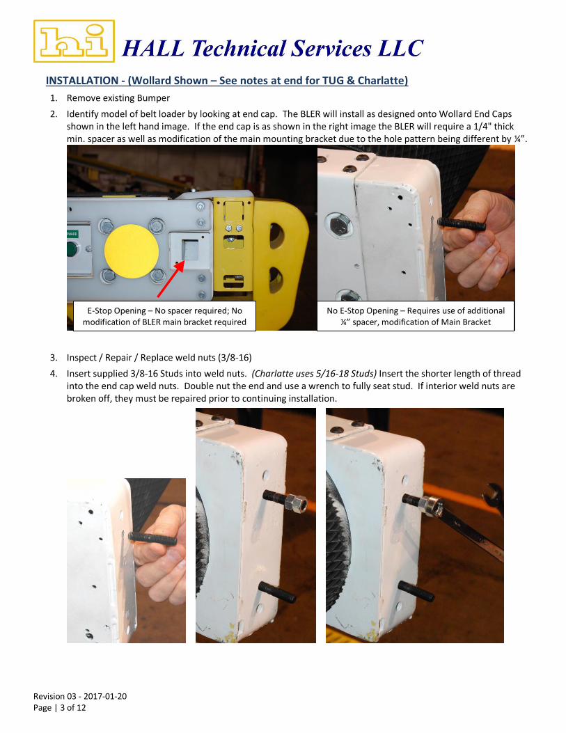
2. Identify model of belt loader by looking at end cap. The BLER will install as designed onto Wollard End Caps shown in the left hand image. If the end cap is as shown in the right image the BLER will require a 1/4" thick min. spacer as well as modification of the main mounting bracket due to the hole pattern being different by ¼”.
3. Inspect / Repair / Replace weld nuts (3/8-16)
4. Insert supplied 3/8-16 Studs into weld nuts. (Charlatte uses 5/16-18 Studs) Insert the shorter length of thread into the end cap weld nuts. Double nut the end and use a wrench to fully seat stud. If interior weld nuts are broken off, they must be repaired prior to continuing installation.
E-Stop Opening – No spacer required; No modification of BLER main bracket required
No E-Stop Opening – Requires use of additional ¼” spacer, modification of Main Bracket
Revision 03 - 2017-01-20 Page | 4 of 12
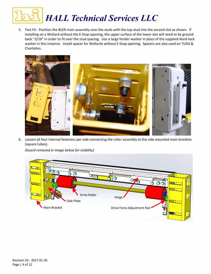
5. Test Fit - Position the BLER main assembly over the studs with the top stud into the second slot as shown. If installing on a Wollard without the E-Stop opening, the upper surface of the lower slot will need to be ground back ~3/16” in order to fit over the stud spacing. Use a large fender washer in place of the supplied Nord-lock washer in this instance. Install spacer for Wollards without E-Stop opening. Spacers are also used on TUGS & Charlattes.
6. Loosen all four internal fasteners per side connecting the roller assembly to the side mounted main brackets (square tubes).
(Guard removed in image below for visibility)
Main Bracket
Drive Roller
Side Plate Hinge
Drive Force Adjustment Nut
Revision 03 - 2017-01-20 Page | 5 of 12
7. Center the assembly on the belt and tighten the mounting nuts.
8. Insert “TEE” Gap gauge (supplied) one at each end of the roller as shown below.
9. Insert 0.03” spacer between main roller (black) and stainless steel angle, one at each end. Push the roller assembly into the belt and tighten the top bolt only on each side.
Revision 03 - 2017-01-20 Page | 6 of 12
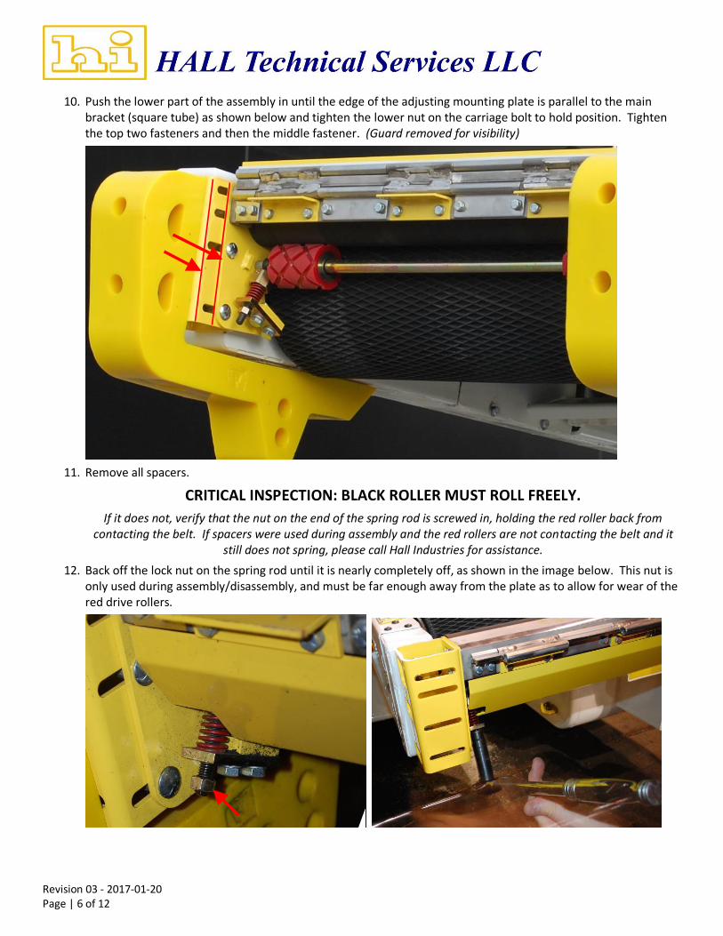
10. Push the lower part of the assembly in until the edge of the adjusting mounting plate is parallel to the main bracket (square tube) as shown below and tighten the lower nut on the carriage bolt to hold position. Tighten the top two fasteners and then the middle fastener. (Guard removed for visibility)
11. Remove all spacers.
CRITICAL INSPECTION: BLACK ROLLER MUST ROLL FREELY.
If it does not, verify that the nut on the end of the spring rod is screwed in, holding the red roller back from contacting the belt. If spacers were used during assembly and the red rollers are not contacting the belt and it
still does not spring, please call Hall Industries for assistance.
12. Back off the lock nut on the spring rod until it is nearly completely off, as shown in the image below. This nut is only used during assembly/disassembly, and must be far enough away from the plate as to allow for wear of the red drive rollers.
Revision 03 - 2017-01-20 Page | 7 of 12
13. The unit is now ready for testing. Remove the spacers and run the belt forwards and back checking the gap between the rejection roller (black) and the belt, especially at the splice. If the gap is uneven, too large or is making contact repeat the adjustment procedure to ensure an even gap of ~1/8". Check for sufficient drive force by applying pressure to the black roller while running. You should not be able to stop the rotation by hand pressure. Be CAREFUL to avoid the pinch point.
14. Install flip ramp subassembly by removing the hinge pin from flip ramp subassembly, positioning the hinge as shown and driving the pin back through. If pin drives in very easily rotate pin until bulge is oriented up and down for maximum engagement with hinge. If pin is still loose in the hinge bend the very end of the pin by impacting with a hammer. Pin must be secure so it doesn’t walk out during use.
Revision 03 - 2017-01-20 Page | 8 of 12
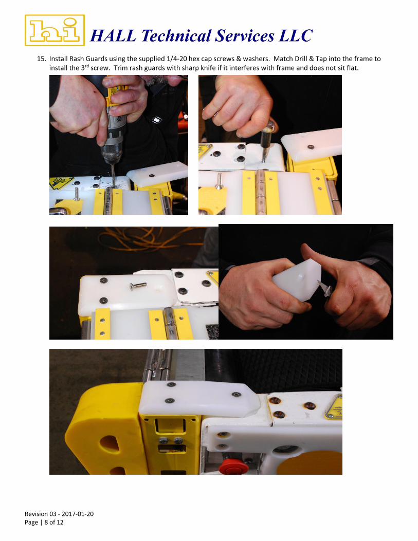
15. Install Rash Guards using the supplied 1/4-20 hex cap screws & washers. Match Drill & Tap into the frame to install the 3rd screw. Trim rash guards with sharp knife if it interferes with frame and does not sit flat.
Revision 03 - 2017-01-20 Page | 9 of 12
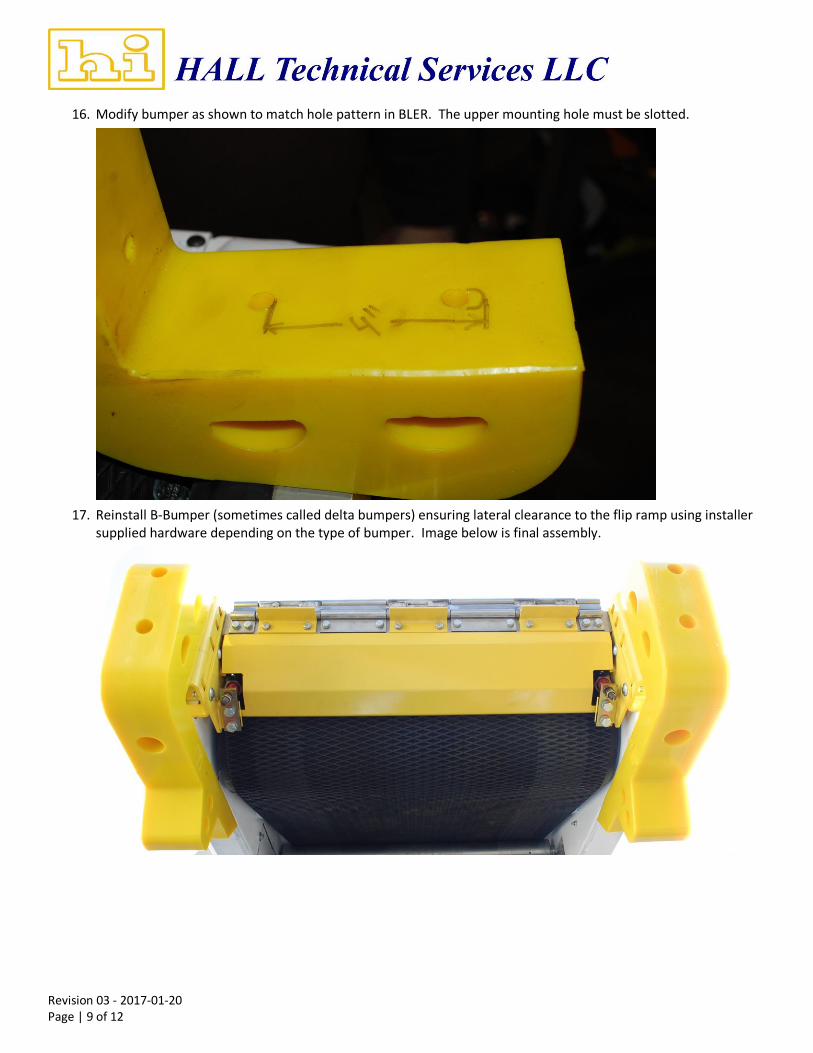
16. Modify bumper as shown to match hole pattern in BLER. The upper mounting hole must be slotted.
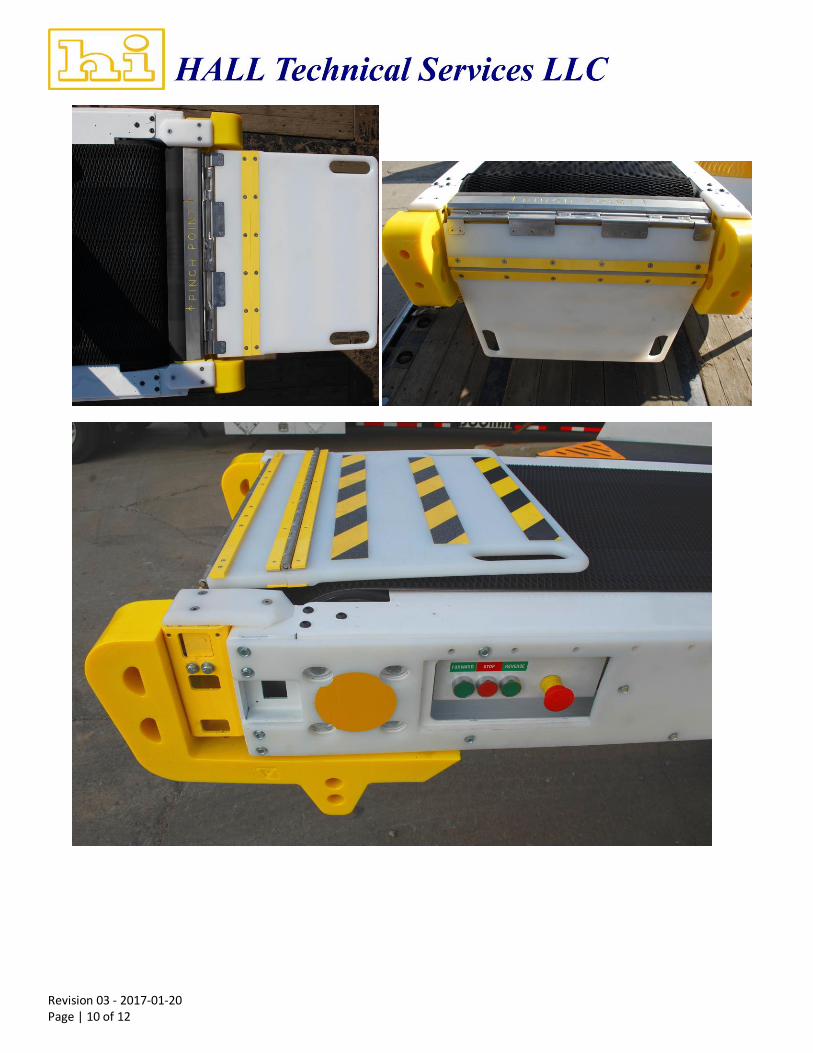
17. Reinstall B-Bumper (sometimes called delta bumpers) ensuring lateral clearance to the flip ramp using installer supplied hardware depending on the type of bumper. Image below is final assembly.
Revision 03 - 2017-01-20 Page | 10 of 12
Revision 03 - 2017-01-20 Page | 11 of 12
INSTALLATION NOTES - TUG & Charlatte 150E
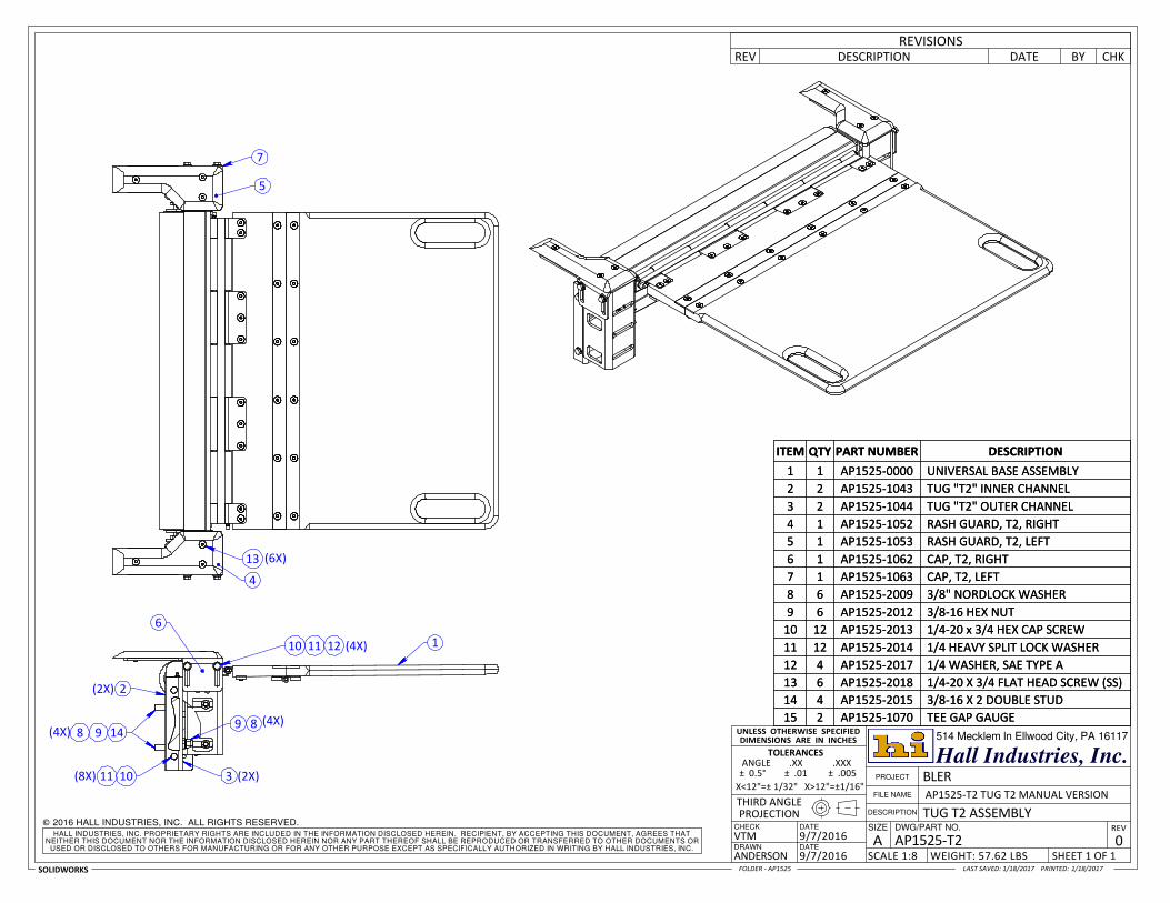
When installing on TUG T1 or T2 and Charlatte 150E adapter brackets or spacers are used to space the BLER away from the frame and different rash guards are used. See drawings for additional detail.
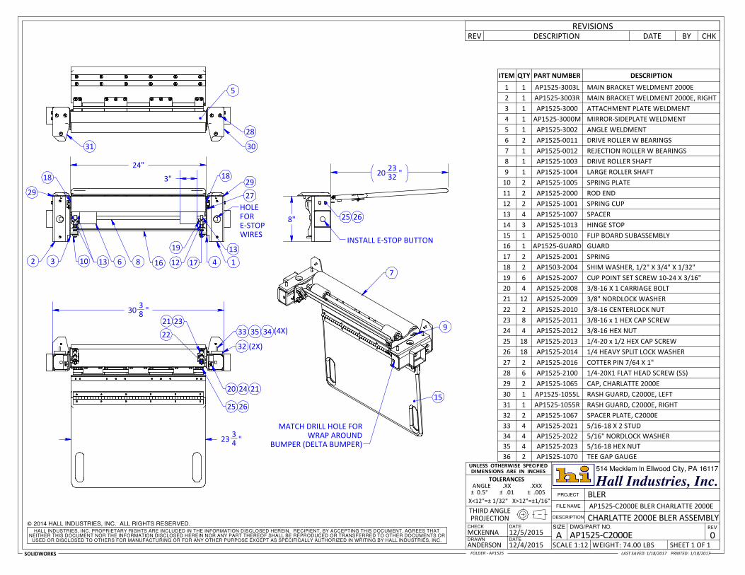
INSTALLATION NOTES - Charlatte 2000E
When installing on the Charlatte 2000E the existing E-Stop box is removed and the E-Stop is inserted into the C2000E main brackets. Match drill and tap into the bracket to attach the white side scuff guard to the main brackets. See drawings for additional detail.
Installation Questions - Call 412-287-7038 Scott Kennedy or 412-719-2183 Volus McKenna
Revision 03 - 2017-01-20 Page | 12 of 12
INSTALLATION NOTES – FINAL INSPECTION CHECKLIST
Verify Rejection Roller (Black) turns in opposite direction of belt.
Verify that the belt does not rub on the Rejection Roller.
Verify that locknuts at end of spring rods is turned to very end of rod
Verify that all hardware is tight.
Verify that rash guards are tight down to top of bed frame. Do not allow any opening that can catch baggage.
PM INSPECTION CHECKLIST
Inspect condition of Rejection Roller. Large gouges that cause gaps larger than 1/8” are cause for replacement.
Inspect condition of Drive Rollers (Red). Remove guard to perform inspection. If all tread is worn off then rollers should be replaced.
Inspect Rejection Roller drive force by turning belt on and trying to stop the roller from turning with hand pressure. Check in both directions. Rejection roller should not be able to be stopped with medium to high levels of hand pressure. Be careful to not catch a finger in the pinch point.
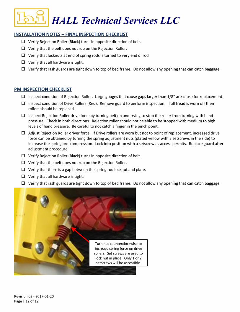
Adjust Rejection Roller driver force. If Drive rollers are worn but not to point of replacement, increased drive force can be obtained by turning the spring adjustment nuts (plated yellow with 3 setscrews in the side) to increase the spring pre-compression. Lock into position with a setscrew as access permits. Replace guard after adjustment procedure.
Verify Rejection Roller (Black) turns in opposite direction of belt.
Verify that the belt does not rub on the Rejection Roller.
Verify that there is a gap between the spring rod locknut and plate.
Verify that all hardware is tight.
Verify that rash guards are tight down to top of bed frame. Do not allow any opening that can catch baggage.
Turn nut counterclockwise to increase spring force on drive rollers. Set screws are used to lock nut in place. Only 1 or 2 setscrews will be accessible.
9 46 5
2810 (4X)
(2X)SHIP LOOSE
3
7
7
1
(2X)
Hall Industries, Inc.
DATE
DWG/PART NO.DATE SIZE
DRAWN
CHECK
SHEET 1 OF 1
9/7/2016NEITHER THIS DOCUMENT NOR THE INFORMATION DISCLOSED HEREIN NOR ANY PART THEREOF SHALL BE REPRODUCED OR TRANSFERRED TO OTHER DOCUMENTS OR
CBM
X<12"=± 1/32" X>12"=±1/16"
1/18/2017
USED OR DISCLOSED TO OTHERS FOR MANUFACTURING OR FOR ANY OTHER PURPOSE EXCEPT AS SPECIFICALLY AUTHORIZED IN WRITING BY HALL INDUSTRIES, INC.
THIRD ANGLE DESCRIPTION
REV
PROJECTION
12/10/2015
TOLERANCES
ANGLE .XX .XXX
2015 HALL INDUSTRIES, INC. ALL RIGHTS RESERVED.
SOLIDWORKS
HALL INDUSTRIES, INC. PROPRIETARY RIGHTS ARE INCLUDED IN THE INFORMATION DISCLOSED HEREIN. RECIPIENT, BY ACCEPTING THIS DOCUMENT, AGREES THAT
NEITHER THIS DOCUMENT NOR THE INFORMATION DISCLOSED HEREIN NOR ANY PART THEREOF SHALL BE REPRODUCED OR TRANSFERRED TO OTHER DOCUMENTS OR 12/5/2015
1/18/2017
THIRD ANGLE
WEIGHT: 74.00 LBS
A
SOLIDWORKS
SCALE 1:12
REV
DESCRIPTION
DIMENSIONS ARE IN INCHES
LAST SAVED: 1/18/2017 PRINTED:
UNLESS OTHERWISE SPECIFIED
FOLDER - AP1525
NOTES:
1. SEE SHEET 2 FOR SECTION A-A AND DETAILS B & C
ITEM QTY PART NUMBER DESCRIPTION
1 2 AP1525-1008 MAIN BRACKET
2 1 AP1525-3000 ATTACHMENT PLATE WELDMENT
3 1 AP1525-3000M MIRROR-SIDEPLATE WELDMENT
4 1 AP1525-3002 ANGLE WELDMENT
5 1 AP1525-0010 FLIP BOARD SUBASSEMBLY
6 2 AP1525-0011 DRIVE ROLLER W BEARINGS
7 1 AP1525-0012 REJECTION ROLLER W BEARINGS
8 2 AP1525-1001 SPRING CUP
9 1 AP1525-1003 DRIVE ROLLER SHAFT
10 1 AP1525-1004 LARGE ROLLER SHAFT
11 2 AP1525-1005 SPRING PLATE
12 4 AP1525-1007 SPACER
13 3 AP1525-1013 HINGE STOP
14 1 AP1525-GUARD GUARD
16 2 AP1525-2000 ROD END
16 2 AP1525-2001 SPRING
17 2 AP1503-2004 SHIM WASHER, 1/2" X 3/4" X 1/32"
18 6 AP1525-2007 CUP POINT SET SCREW 10-24 X 3/16"
19 4 AP1525-2008 3/8-16 X 1 CARRIAGE BOLT
20 12 AP1525-2009 3/8" NORDLOCK WASHER
21 2 AP1525-2010 3/8-16 CENTERLOCK NUT
22 8 AP1525-2011 3/8-16 x 1 HEX CAP SCREW
24 4 AP1525-2012 3/8-16 HEX NUT
24 14 AP1525-2013 1/4-20 x 3/4 HEX CAP SCREW
25 14 AP1525-2014 1/4 HEAVY SPLIT LOCK WASHER
26 2 AP1525-2016 COTTER PIN 7/64 X 1"
Hall Industries, Inc.
DATE
DWG/PART NO.DATE SIZE
DRAWN
CHECK
SHEET 1 OF 2
± 0.5° ± .01 ± .005
THIRD ANGLE PROJECTION
MCKENNA
514 Mecklem ln Ellwood City, PA 16117
X<12"=± 1/32" X>12"=±1/16"
TOLERANCES
DIMENSIONS ARE IN INCHES
REV
UNIVERSAL BASE ASSEMBLY
ANGLE .XX .XXX
2015 HALL INDUSTRIES, INC. ALL RIGHTS RESERVED.
SOLIDWORKS
PROJECT
NEITHER THIS DOCUMENT NOR THE INFORMATION DISCLOSED HEREIN NOR ANY PART THEREOF SHALL BE REPRODUCED OR TRANSFERRED TO OTHER DOCUMENTS OR
DESCRIPTION
AP1525-0000HALL INDUSTRIES, INC. PROPRIETARY RIGHTS ARE INCLUDED IN THE INFORMATION DISCLOSED HEREIN. RECIPIENT, BY ACCEPTING THIS DOCUMENT, AGREES THAT
USED OR DISCLOSED TO OTHERS FOR MANUFACTURING OR FOR ANY OTHER PURPOSE EXCEPT AS SPECIFICALLY AUTHORIZED IN WRITING BY HALL INDUSTRIES, INC.0