1AEA-SM-286 /95P BENCHMARKING THE Q/TRAN THERMAL ANALYSIS COMPUTER CODE* R.D. MANTEUFEL, D.E. KLEIN The University of Texas at Austin, Austin, Texas H. R. YOSHIMURA Sa ndia National Labor ato ries, Albuqu erqu e, New Mexico United States of America Presented by G. C Allen, Jr. Abstraa BENCHMARKING THE Q/TRAN THERMAL ANALYSIS COMPUTER CODE. Q/TRAN, a new thermal analysis computer code, was examined for its use in modelling the responses of radioactive material shipping casks under accident conditions. A comparison between Q/ TRAN and HEATING-6 was made using four benchmark problems chosen for their cask-like geometries and similarity to packaging thermal environments. HEATING-6 was chosen for comparison because HEATING-5, a predecessor to HEATING-6, was used in previous cask analyses. Modelling capabilities for each code are discussed as they relate to the four benchmark model problems. Q/TRAN was determined to be advantageous because of (I) its superior nume- rical algorithms and (2) the pre- and postprocessing capabilities (with PATRAN) that allow the graphical display of flexible meshing schemes and thermal results. INTRODUCTION Q/TRANl is a thermal analysis computer code that can be used to model the response of radioactive material shipping casks in accident conditions as described in 10CFR71 .2 Sandia National Laboratories (hereafter Sandia ) has been involved in the design and testing of radioactivQ material shipping casks . Sandia contracted with the University of Texas at Austin to benchmark and compare Q/TRAN with computer codes used in prior thermal analyses of shipping casks.3 From previous evaluations of shipping cask fi re tests, we found that the quality of the predicted response of the cask may vary significantly with the computer code's ability to model the complex physical phenomena.3,4 Q/TRAN • Work supported by the US Depart ment of Energy under Contract No. DE-AC04- 76DP00789. 465
Transcript
1AEA-SM-286/95P
BENCHMARKING THE Q/TRAN THERMAL ANALYSIS COMPUTER CODE*
R.D. MANTEUFEL, D.E. KLEIN The University of Texas at Austin, Austin, Texas
H. R. YOSHIMURA Sa ndia National Laboratories, Albuquerque, New Mexico
United States of America
Presented by G. C Allen, Jr.
Abstraa
BENCHMARKING THE Q/TRAN THERMAL ANALYSIS COMPUTER CODE. Q/T RAN, a new thermal analysis computer code, was examined for its use in modelling
the responses of radioactive material shipping casks under accident conditions. A comparison between Q/TRAN and HEATING-6 was made using four benchmark problems chosen for their cask-like geometries and similarity to packaging thermal environments. HEATING-6 was chosen for comparison because HEATING-5, a predecessor to HEATING-6, was used in previous cask analyses. Modelling capabilities for each code are discussed as they relate to the four benchmark model problems. Q/TRAN was determined to be advantageous because of (I) its superior numerical algorithms and (2) the pre- and postprocessing capabilities (with PATRAN) that allow the graphical display of flexible meshing schemes and thermal results.
INTRODUCTION
Q/TRANl is a thermal analysis computer code that can be used to model the response of radioactive material shipping casks in accident conditions as described in 10CFR71 . 2 Sandia National Laboratories (hereafter Sandia ) has been involved in the design and testing of radioactivQ material shipping casks . Sandia contracted with the University of Texas at Austin to benchmark and compare Q/TRAN with computer codes used in prior thermal analyses of shipping casks.3 From previous evaluations of shipping cask f i re tests, we found that the quality of the predicted response of the cask may vary significantly with the computer code's ability to model the complex physical phenomena.3,4 Q/TRAN
• Work supported by the US Department of Energy under Contract No. DE-AC04-
76DP00789.
465
REGION I
ADIABATIC SURFACE
ADIABATIC SURFACE
REGION 1 REGION 2 --1--1--
I
CONVECTIVE COOLING
qc = h(T s · T ~l
PROBLEM 1
T4
'2
REGION II CASK
6
PROBLEM 3
REGION IV
ENVIRONMENT
TEMPERATURE . . THERMAL Too • ..--~
THERMAL T2 RADIATION
RADIATION
REGION IV
REGION Ill
REGION II
REGION I
THERMAL
T3
PROBLEM 2
T1 , NODE 1 T2. NODE 2 T3. NODE 3
CASK
THERMAL RADIATION
RADIATION " /~
T-~J 1{ ~ 6 . D ENVIRONMENU !l SHIELD TEMPERATU~E wil , if
r:.. THERMAL RADIATION
PROBLEM 4
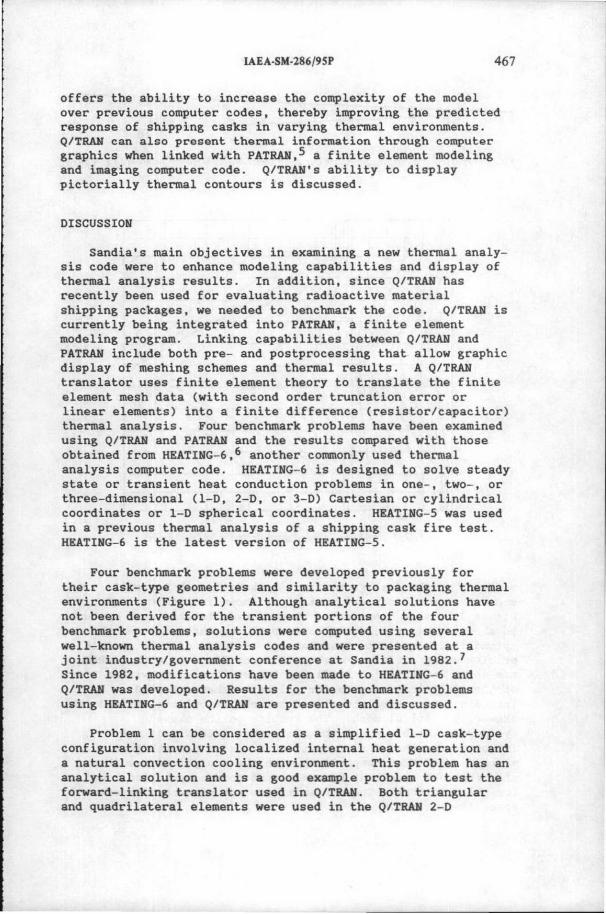
FIG. 1. Geometries of the model problems (Ref. (7]).
-- ·---
~ 0\ 0\
;t > z o-j rt:l c:::: .., ttl r-~
!!!-
IAEA·SM-l86/9SP 467
offers the ability to increase the complexity of the model over previous computer codes, thereby improving the predicted response of shipping casks in varying thermal environments. Q/TRAH can also present thermal information through computer graphics when linked with PATRAN,5 a finite element modeling and imaging computer code. Q/TRAN's ability to display pictorially thermal contours is discussed.
DISCUSSION
Sandia's main objectives in exam~n~ng a new thermal anal ysis code were to enhance modeling capabilities and display of thermal analysis results . In additi on, since Q/TRAN has recently been used for evaluating radioactive material shipping packages, we needed to benchmark the code . Q/TRAN is currently being integrated into PATRAN, a finite element modeling program. Linking capabilities between Q/TRAN and PATRAN include both pre- and postprocessing that allow graphic display of meshing schemes and thermal results. A Q/TRAN translator uses finite element theory to translate the finite element mesh data (with second order truncation error or linear elements) into a finite difference (resistor/ capacitor ) thermal analysis . Four benchmark problems have been examined using Q/TRAH and PATRAH and the results compared with those obtained from HEATING- 6,6 another commonly used thermal analysis computer code. HEATING- 6 is designed to solve steady state or transient heat conduction problems in one- , two- , or three- dimensional (1- D, 2- 0, or 3- 0) Cartesian or cylindrical coordinates or 1- D spherical coordinates . HEATING- 5 was used in a previous thermal analysis of a shipping cask fire test . HEATING- 6 is the latest version of HEATING- 5.
Four benchmark problems were developed previously for their cask-type geometries and similarity to packaging thermal environments (Figure 1). Although analytical solutions have not been derived for the transient portions of the four benchmark problems, solutions were computed using several well- known thermal analysis codes and were presented at a joint industry/government conference at Sandia in 1982.7 Since 1982, modifications have been made to HEATING- 6 and Q/TRAH was developed. Results for the benchmark problems using HEATING- 6 and Q/TRAH are presented and discussed .
Problem 1 can be considered as a simplified 1- D cask- type configuration involving localized internal heat generation and a natural convection cooling environment . This problem has an analytical solution and is a good example problem to test the forward-linking translator used in Q/ TRAN. Both triangular and quadrilateral elements were used in the Q/TRAN 2-D
468 MANTEUFEL et al.
1 e 4 5 6
FIG. 2. Problem 1 linear isoparametric Cartesian quadrilateral mesh (5° segment of a cylinder).
FIG. 3. Problem 1 skewed JIUadrilateral cylindrical mesh.
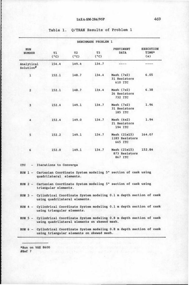
modeling of the cask geometry. A standard mesh for a 5° segment of a cylindrical section is shown in Figure 2. In Figure 3, a more complicated skewed quadrilateral mesh system is shown. This procedure tested both the Cartesian and the cylindrical coordinate translators. Results of this example problem using different meshes (Figures 2 and 3) with Q/TRAH are shown in Table l. Predicted temperatures were within 3°C of the analytical results for all mesh schemes tested, including the quadrilateral and triangular cylindrical and the skewed cylindrical mesh . The results on the skewed cylindrical mesh support the claim that Q/TRAN does not introduce zeroth-order truncation errors on nonorthogonal meshes . HEATING-6 comparisons with the analytical results also provided excellent agreement and good computation time for the solutions . These results are not presented because of space limitations.
IAEA-SM-286/9SP 469
Table 1. Q/TRAN Results of Problem 1
BENCHMARK PROBLEM 1
RUN NUMBER Tl
c•c> T2
c•c> T3
c•c>
PERTINENT DATA
EXECUTION TIME* (s)
Analytical Solution#
1
2
3
5
6
154.4 149.4
152.1 148.7
152.1 148.7
152.4 149.1
152.4 149.0
152.2 149.1
152.0 149.1
lTC Iterations to Converge
134.7
134.4
13.4. 4
134.7
134.7
134 . 7
134.7
Mesh (7x2) 6.05 31 Resistors
610 lTC
Mesh (7x2) 6.38 26 Resistors
732 lTC
Mesh (7x2) 1.96 31 Resistors
185 ITC
Mesh (6x2) 1.94 21 Resistors
194 ITC
Mesh (21x15) 164.07 1183 Resistors
665 lTC
Mesh (21x15) 152.84 873 Resistors
867 ITC
RUN 1 - Cartesian coordinate System modeling 5• section of cask using quadrilateral elements.
RUN 2 - Cartesian coordinate System modeling 5• section of cask using triangular elements.
RUN 3 - Cylindrical Coordinate System modeling 0.1 m depth section of cask using quadrilateral elements.
RUN 4 - Cylindrical Coordinate System modeling 0.1 m depth section of cask using triangular elements .
RUN 5 - Cylindrical Coordinate System modeling 0.8 m depth section of cask using quadrilateral elements on skewed mesh.
RUN 6 - Cylindrical Coordinate System modeling 0.8 m depth section of cask using triangular elements on skewed mesh.
*Run on VAX 8600 #Ref 7
470
.. w N u; a. w t; w :::E i=
MANTEUFEL et al.
1000 0 T1
OT2 800
u !.. w
600 a:
6T3 • TINF
ft:.-t>-ir-6
:I
~ a:
400 w A. :IE w ~
200
1\ \
.oD ~~88:8:8 lJ.c-D~O" f1!V" ~-6-o-o-.>o
0 0 10 20 30 40 50 60 70 80 90
TIME(min)
FIG. 4. Temperature-time history for problem 2.
I - . ' i
: :
' -···· t ,. ·--!· -·~··· .. i--·····-··-i·-··--··-· 25
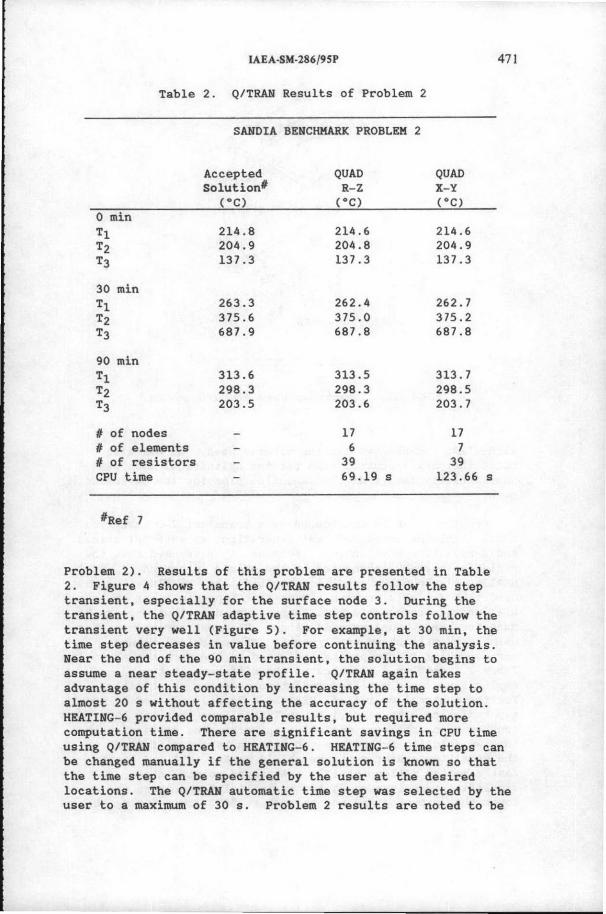
Problem 2 may be considered a transient 1-D cask- type model involving localized internal heat generation, internal gap radiation, and a highly radiative environment. Q/ TRAN was employed to solve this problem using quadrilateral elements in both Cartesian and cylindrical coordinate systems. Three nodal temperatures as a function of time are shown in Figure 4 ; Figure 5 is a plot of time step as a function of time . Node 1 is located between the heat- generation source and solid shield, node 2 is between the solid shield and the void region and node 3 is on the outer surface (see Figure 1,
fl of nodes 17 17 II of elements 6 7 fl of resistors 39 39 CPU time 69.19 s 123.66 s
#Ref 7
Problem 2). Results of this problem are presented in Table 2 . Figure 4 shows that the Q/TRAN results follow the step transient, especially for the surface node 3. During the transient, the Q/TRAN adaptive time step controls follow the transient very well (Figure 5) . For example, at 30 min , the time step decreases in value before continuing the analysis. Near the end of the 90 min transient, the solution begins to assume a near steady- state profile. Q/TRAN again takes advantage of this condition by increasing the time step to almost 20 s without affecting the accuracy of the solution. HEATING- 6 provided comparable results, but required more computation time . There are significant savings in CPU time using Q/TRAN compared to HEATING-6. HEATING- 6 time steps can be changed manually if the general solution is known so that the time step can be specified by the user at the desired locations. The Q/TRAN automatic time step was selected by the user to a maximum of 30 s . Problem 2 results are noted to be
472 MANTEUFEL et al.
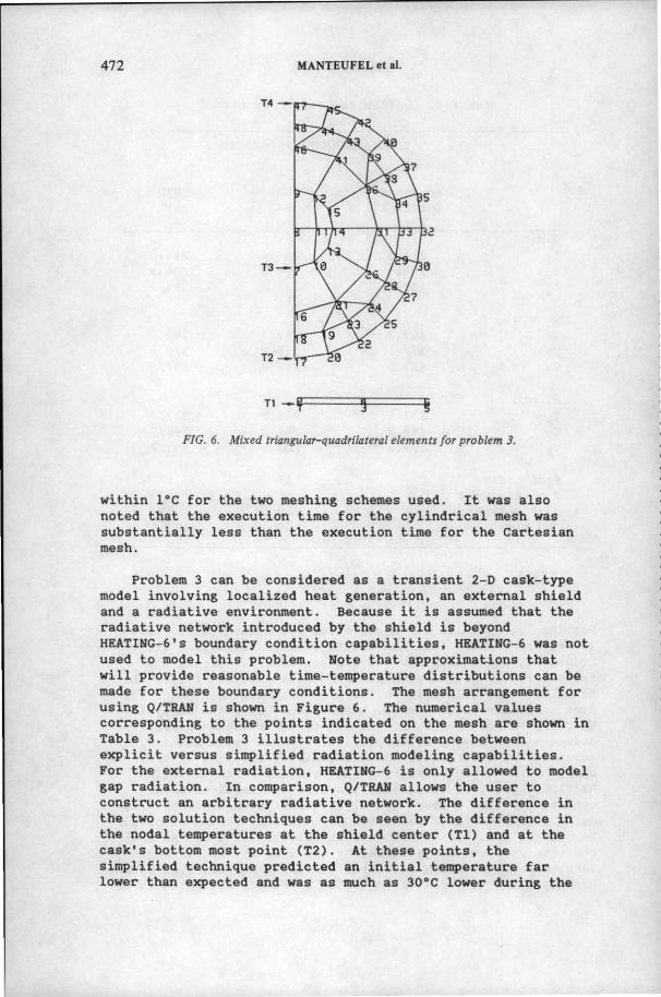
FIG. 6. Mixed triangular-quadrilateral elements for problem 3.
within l °C for the two meshing schemes used. It was also noted that the execution time for the cylindrical mesh was substantially less than the execution time for the Cartesian mesh .
Problem 3 can be considered as a transient 2- D cask- type model involving localized heat generation , an external shield and a radiative environment . Because it is assumed that the radiative network introduced by the shield is beyond HEATING- 6's boundary condition capabilities, HEATING- 6 was not used to model this problem. Note that approximations that will provide reasonable time- temperature distributions can be made for these boundary conditions . The mesh arrangement for using Q/ TRAN is shown in Figure 6. The numerical values corresponding to the points indicated on the mesh are shown in Table 3. Problem 3 illustrates the difference between explicit versus simplified radiation modeling capabilities. For the external radiation, HEATING- 6 is only allowed to model gap radiation . In comparison, Q/TRAN allows the user to construct an arbitrary radiative network. The difference in the two solution techniques can be seen by the difference in the nodal temperatures at the shield center (Tl) and at the cask's bottom most point (T2) . At these points, the simplified technique predicted an initial temperature far lower than expected and was as much as 30°C lower during the
1AEA-SM-'286/9SP 473
Table 3. Benchmark Results of Problem 3
BENCHMARK PROBLEM 3
RUM TIHR Tl T2 T3 T4 PERTIIIIUIT !XI!:CUTIOII WMBER .1!!!nl i.:£1 ~ ~ ~ DATA TIHR"' ~-~
transient. For the boundary conditions of Problem 3, the Q/TRAN allowed radiative network was deemed a distinct advantage over HEATING- 6 modeling capabilities .
Problem 4 combines the aspects of problems 2 and 3, having an internal annular gap region and an external radiation shield. HEATING- 6 was not used to solve this problem because it was felt that the necessary boundary condition simplification would have eliminated the very effects the added boundary conditions were expected to produce . The problem was designed to note the effects of the shield and the inner annular region. Q/TRAN was used to model the entire explicit radiation network . Q/TRAN's results agreed with the consensus results to within
474 MANTEUFELet~.
soc as shown in Table 4 . Using the postp~ocessing capabilities of PATRAN, the effects of the shield was observed. From a few of the thermal contour plots, it was noted that the thermal effects of the shield are lost sho~tly (within 10 min) of the sharp t~ansients introduced by the fi~e at 0 min and at 30 min. The graphical feedback allowed by Q/TRAN is a definite advantage .