Vol. 135 (2019) ACTA PHYSICA POLONICA A No. 3 Bending Analysis of Laminated Two-Dimensional Piezoelectric Quasicrystal Plates with Functionally Graded Material Properties Yang Li a,b , Lianzhi Yang c and Yang Gao d, * a College of Engineering, China Agricultural University, Beijing 100083, China b Department of Mechanical and Power Engineering, Yingkou Institute of Technology, Yingkou 115014, China c School of Civil and Resource Engineering, University of Science and Technology Beijing, Beijing 100083, China d College of Science, China Agricultural University, Beijing 100083, China (Received July 2, 2018; in final form January 18, 2019) This paper presents an exact solution for a functionally graded multilayered two-dimensional piezoelectric quasicrystal plate with simply supported boundary conditions. The material properties of the functionally graded plate are assumed to be exponentially distributed along the thickness direction. Based on the pseudo-Stroh formalism, an exact solution for a functionally graded plate is derived, and the exact solution for the corresponding multilayered case is obtained in terms of the propagator matrix method. Numerical examples show the influences of functionally graded exponential factor, stacking sequence, and phonon–phason coupling coefficient on the plate. The obtained results should be useful for the analysis and design of the functionally graded two-dimensional piezoelectric quasicrystal plate. DOI: 10.12693/APhysPolA.135.426 PACS/topics: quasicrystals, functionally graded materials, piezoelectricity, plates, exact solution 1. Introduction Functionally graded (FG) materials have been widely used in smart structure. Due to the smooth and con- tinuous change of material properties along one direc- tion, they can eliminate stress concentration and im- prove the bonding strength at the interfaces of the layers. Such smart structure in form of plate made of FG ma- terials and FG piezoelectric materials is very common in engineering. Three-dimensional analysis of thick FG piezoelectric plate was done by utilizing the element-free- Galerkin method [1]. Guo et al. [2] studied the size- dependent behavior of the FG plate under surface load by using the modified couple-stress theory. Sladek et al. [3] proposed a meshless method based on the local Petrov– Galerkin approach to investigate the bending behavior of FG plate. Li et al. [4] derived the analytical solu- tion for the axisymmetric problem of FG circular plates. Wu et al. [5] presented the exact solution of FG magneto- electro-elastic rectangular plates using a modified Pagano method. The elasticity solution of the FG plate subjected to a special family of biharmonic polynomial loading was obtained in terms of three-dimensional theory of elastic- ity [6]. Liu and Zhong [7], and Zhong and Shang [8] investigated the thermoelastic and piezothermoelectric problems of a FG rectangular plate, respectively. Pan and Han [9] obtained the exact solution for the FGM magneto-electro-elastic plates based on the pseudo-Stroh formalism. * corresponding author; e-mail: [email protected]As new-type solid materials, quasicrystals (QCs) were discovered from the diffraction image of rapidly cooled Al–Mn alloys by Shechtman in early 1980s [10]. QCs have a long-range quasiperiodic translational order and a long- range orientational order [11, 12]. Two lower frequency excitations, which are phonon and phason, are considered in the elastic energy theory of QCs [13]. Attributing to the quasi-periodic structure, QCs possess many desirable properties, such as high hardness, high wear resistance, low adhesion, and low level of porosity [14, 15]. Piezo- electricity has been verified to be a vital physical prop- erty of QCs [16, 17]. Owing to the quasi-periodic atomic arrangement of QCs, they are expected to be used as sen- sor in intelligent structures, thin films, coating surface of engines, thermal barrier coating, and coating surface of spacecraft’s wings [18–20]. Due to the unique properties and potential applications, QCs have attracted much at- tention in a wide range of research fields, such as defect problems [19, 20] and mechanical behavior analysis in the layered smart structure [21–24]. FG piezoelectric QC (PQC) materials consider FG ef- fect and piezoelectric effect together, which are expected to be used as sensors and actuators to monitor and con- trol the response of structures. Due to the advantages of FG piezoelectric materials and QCs, FG PQCs can not only realize the conversion of mechanical energy and electrical energy, but also enhance the life span and reli- ability of piezoelectric devices. With the development of preparation technology of FG QCs [25], the study on the smart structure made of FG PQCs becomes particularly important. Motivated by this, an exact solution for a FG layered two-dimensional (2D) PQC plate is presented in this paper. Based on the pseudo-Stroh formalism [26], (426)
Transcript
Vol. 135 (2019) ACTA PHYSICA POLONICA A No. 3
Bending Analysis of LaminatedTwo-Dimensional Piezoelectric Quasicrystal Plates
with Functionally Graded Material PropertiesYang Lia,b, Lianzhi Yangc and Yang Gaod,∗
aCollege of Engineering, China Agricultural University, Beijing 100083, ChinabDepartment of Mechanical and Power Engineering, Yingkou Institute of Technology, Yingkou 115014, China
cSchool of Civil and Resource Engineering, University of Science and Technology Beijing, Beijing 100083, ChinadCollege of Science, China Agricultural University, Beijing 100083, China
(Received July 2, 2018; in final form January 18, 2019)This paper presents an exact solution for a functionally graded multilayered two-dimensional piezoelectric
quasicrystal plate with simply supported boundary conditions. The material properties of the functionally gradedplate are assumed to be exponentially distributed along the thickness direction. Based on the pseudo-Strohformalism, an exact solution for a functionally graded plate is derived, and the exact solution for the correspondingmultilayered case is obtained in terms of the propagator matrix method. Numerical examples show the influencesof functionally graded exponential factor, stacking sequence, and phonon–phason coupling coefficient on the plate.The obtained results should be useful for the analysis and design of the functionally graded two-dimensionalpiezoelectric quasicrystal plate.
Functionally graded (FG) materials have been widelyused in smart structure. Due to the smooth and con-tinuous change of material properties along one direc-tion, they can eliminate stress concentration and im-prove the bonding strength at the interfaces of the layers.Such smart structure in form of plate made of FG ma-terials and FG piezoelectric materials is very commonin engineering. Three-dimensional analysis of thick FGpiezoelectric plate was done by utilizing the element-free-Galerkin method [1]. Guo et al. [2] studied the size-dependent behavior of the FG plate under surface load byusing the modified couple-stress theory. Sladek et al. [3]proposed a meshless method based on the local Petrov–Galerkin approach to investigate the bending behaviorof FG plate. Li et al. [4] derived the analytical solu-tion for the axisymmetric problem of FG circular plates.Wu et al. [5] presented the exact solution of FG magneto-electro-elastic rectangular plates using a modified Paganomethod. The elasticity solution of the FG plate subjectedto a special family of biharmonic polynomial loading wasobtained in terms of three-dimensional theory of elastic-ity [6]. Liu and Zhong [7], and Zhong and Shang [8]investigated the thermoelastic and piezothermoelectricproblems of a FG rectangular plate, respectively. Panand Han [9] obtained the exact solution for the FGMmagneto-electro-elastic plates based on the pseudo-Strohformalism.
As new-type solid materials, quasicrystals (QCs) werediscovered from the diffraction image of rapidly cooledAl–Mn alloys by Shechtman in early 1980s [10]. QCs havea long-range quasiperiodic translational order and a long-range orientational order [11, 12]. Two lower frequencyexcitations, which are phonon and phason, are consideredin the elastic energy theory of QCs [13]. Attributing tothe quasi-periodic structure, QCs possess many desirableproperties, such as high hardness, high wear resistance,low adhesion, and low level of porosity [14, 15]. Piezo-electricity has been verified to be a vital physical prop-erty of QCs [16, 17]. Owing to the quasi-periodic atomicarrangement of QCs, they are expected to be used as sen-sor in intelligent structures, thin films, coating surface ofengines, thermal barrier coating, and coating surface ofspacecraft’s wings [18–20]. Due to the unique propertiesand potential applications, QCs have attracted much at-tention in a wide range of research fields, such as defectproblems [19, 20] and mechanical behavior analysis in thelayered smart structure [21–24].
FG piezoelectric QC (PQC) materials consider FG ef-fect and piezoelectric effect together, which are expectedto be used as sensors and actuators to monitor and con-trol the response of structures. Due to the advantagesof FG piezoelectric materials and QCs, FG PQCs cannot only realize the conversion of mechanical energy andelectrical energy, but also enhance the life span and reli-ability of piezoelectric devices. With the development ofpreparation technology of FG QCs [25], the study on thesmart structure made of FG PQCs becomes particularlyimportant. Motivated by this, an exact solution for a FGlayered two-dimensional (2D) PQC plate is presented inthis paper. Based on the pseudo-Stroh formalism [26],
the solution for a FG 2D PQC plate is obtained, and theexact solution for the corresponding multilayered case isderived by using the propagator matrix method. In thenumerical examples, the influences of FG exponential fac-tor, stacking sequence, and phonon–phason coupling co-efficient on the FG plate subjected to an electric potentialload on its top surface are studied.
2. Fundamental formulations
The 2D QC refers to a three-dimensional structurewith atomic arrangement being quasi-periodic in a planeand periodic along one direction normal to the plane [27].A 2D PQC with x1-x2 plane being the quasi-periodicplane, x3 being the periodic and poling directions refer-ring to the Cartesian coordinates (x1, x2, x3) is con-sidered in this paper. The static equilibrium equa-tions without body forces and electric charges are givenby [28, 29]:
σij,j = 0, Hmj,j = 0, Dj,j = 0, (2.1)where i, j = 1, 2, 3, and m = 1, 2. σij and Hmj de-note the phonon and phason stresses, respectively; Dj
represents the electric displacements; a subscript commarepresents a partial differentiation.
According to the linear elastic theory of QCs [30], theextended strain–displacement relations are
εij = (ui,j + uj,i)/2, wmj = wm,j , Ej = −φ,j ,(2.2)where εij and wmj represent the phonon and phasonstrains, respectively; ui and wm are displacements in thephonon and phason fields, respectively; Ej and φ denotethe electric fields and electric potential, respectively.
The linear constitutive equations for 2D decagonalPQC with point group 1̄0m2 in Laue 14 can be expressedby the following form [29]:
σ11 =
C11ε11 + C12ε22 + C13ε33 +R1(w11 + w22) − e31E3,
σ22 =
C12ε11 + C11ε22 + C13ε33 −R1(w11 + w22) − e31E3,
σ33 = C13ε11 + C13ε22 + C33ε33 − e33E3,
σ23 = σ32 = 2C44ε23 − e15E2,
σ31 = σ13 = 2C44ε13 − e15E1,
σ12 = σ21 = 2C66ε12 −R1w12 +R1w21,
H11 = R1(ε11 − ε22) +K1w11 +K2w22 − d112E2,
H22 = R1(ε11 − ε22) +K1w22 +K2w11 + d112E2,
H23 = K4w23,
H12 = −2R1ε12 +K1w12 −K2w21 − d112E1,
H13 = K4w13,
H21 = 2R1ε12 −K2w12 +K1w21 − d112E1,
D1 = 2e15ε13 + d112(w12 + w21) + κ11E1,
D2 = 2e15ε23 + d112(w11 − w22) + κ22E2,
D3 = e31(ε11 + ε22) + e33ε33 + κ33E3, (2.3)where Cij denotes the phonon elastic constants, and2C66 = C11 − C12; K1, K2, and K4 represent the pha-son elastic constants; R1 is the phonon–phason couplingelastic constant; e15, e31, and e33 are the piezoelectricconstants in the phonon field; κ11, κ22, and κ33 are thepermittivity constants; d112 represents the piezoelectricconstant in the phason field. Notice that the electro-elastic coupling is not considered in the phason field(i.e., d112 = 0).
The material properties exponentially varying alongthe x3-direction of the FG 2D PQC plate have the fol-lowing distributions:
F (x3) = F 0 eηx3 , (2.4)where F 0 denotes the initial values of material coefficientsin Eq. (2.3). η is the FG exponential factor indicating thedegree of material gradient along the thickness direction.
3. Problem description and general solution
Consider a FG layered 2D PQC plate with the Carte-sian coordinate system (x, y, z), which is shown inFig. 1. The local material coordinate system and theglobal Cartesian coordinate system have the relation(x1, x2, x3) = (x, y, z). The multilayered plate issimply supported with the geometric sizes of the platebeing x × y × z = Lx × Ly × H. The layer j isbonded by the lower interface zj and the upper interfacezj+1. The displacements and z-direction tractions areassumed to be continuous along the interfaces of the lay-ers. The material properties vary exponentially along thez-direction.
Fig. 1. Schematic configuration of a FG layered 2DPQC plate.
The solution of the extended displacement vector of aFG 2D PQC plate takes the following form:
428 Yang Li, Lianzhi Yang, Yang Gao
u =
uxuyuzwxwyφ
= esz
a1 cos px sin qy
a2 sin px cos qy
a3 sin px sin qy
a4 cos px sin qy
a5 sin px cos qy
a6 sin px sin qy
, (3.1)
in which s, a1, a2, a3, a4, a5, and a6 are unknowns to bedetermined, and
p = nπ/Lx, q = mπ/Ly, (3.2)with n and m being two positive integers. Equation (3.1)is one term of a double Fourier series expansion whensolving the general solution. It is clear that the displace-ments and electric potential in Eq. (3.1) satisfy the sim-ply supported boundary conditions, which are shown asfollows:
uy = uz = wy = φ = σxx = 0 at x = 0 and Lx,
ux = uz = wx = φ = σyy = 0 at y = 0 and Ly. (3.3)With the material properties following an exponent-lawdistribution along the thickness direction in Eq. (2.4),we substitute Eq. (3.1) into Eq. (2.2), and subsequentlyinto Eq. (2.3), the extended traction vector can bederived as
t =
σxzσyzσzzHxz
Hyz
Dz
= e(s+η)z
b1 cos px sin qy
b2 sin px cos qy
b3 sin px sin qy
b4 cos px sin qy
b5 sin px cos qy
b6 sin px sin qy
. (3.4)
The two 6 × 1 vectorsa = [a1, a2, a3, a4, a5, a6]
T,
b = [b1, b2, b3, b4, b5, b6]T (3.5)
are introduced to represent the coefficients in Eqs. (3.1)and (3.4), respectively. The superscript “T” denotes avector or matrix transpose. In terms of vector a, vectorb can be expressed as
b =(−RT + sT
)a = − 1
s+ η(Q + sR)a, (3.6)
where the matrices Q, R and T can be expressed by theinitial material coefficients C0
ij , R01, K0
i , e0ij , and d0mij .
Substituting all extended stress components intoEq. (2.1), yields the following equation:[
Q− ηRT + s(R−RT + ηT ) + s2T]a = 0. (3.7)
With the aid of Eq. (3.6), Eq. (3.7) can be recast into thefollowing standard eigenrelation:
N
[a
b
]= s
[a
b
], (3.8)
where
N =
[T−1RT T−1
−Q−RT−1RT −RT−1 − ηI
]. (3.9)
The twelve eigenvalues si and si+6 (i = 1, 2, . . ., 6) are
obtained by solving the eigenrelation in Eq. (3.8). Thefirst six eigenvalues si and the next six eigenvalues si+6
have the relation si+6 = −si − η. The eigenvectors aand b corresponding to eigenvalues can be also obtainedwhen solving Eq. (3.8).
Then the general solution for the extended displace-ment vector in Eq. (3.1) and traction vector in Eq. (3.4)is derived as[
u
t
]=
[I 0
0 eηzI
][A1 A2
B1 B2
]⟨es
∗z⟩[ D1
D2
], (3.10)
whereA1 = [a1,a2,a3,a4,a5,a6] ,
A2 = [a7,a8,a9,a10,a11,a12] ,
B1 = [b1, b2, b3, b4, b5, b6] ,
B2 = [b7, b8, b9, b10, b11, b12] ,⟨es
∗z⟩
= diag[
esiz, e(−si−η)z], (3.11)
with D1 and D2 being two 6× 1 constant column matri-ces to be determined according to the boundary condi-tions, and s∗ includes all twelve eigenvalues solved fromEq. (3.8).
For the lower surface zj of layer j, the constant columnmatrices D1 and D2 in Eq. (3.10) can be expressed as[
D1
D2
]j
= (3.12)
⟨e−s
∗zj⟩[ A1 A2
B1 B2
]−1 [I 0
0 e−ηzjI
][u
t
]zj
.
By virtue of the constant column matrices D1 and D2 inEq. (3.12), the physical quantities at the upper surfacezj+1 of layer j with thickness hj = zj+1 − zj are derivedas [
u
t
]zj+1
= Pj(hj)
[u
t
]zj
, (3.13)
where
Pj(hj) =
[I 0
0 eηzj+1I
][A1 A2
B1 B2
](3.14)
×⟨
es∗(zj+1−zj)
⟩[ A1 A2
B1 B2
]−1 [I 0
0 e−ηzjI
],
and Pj(hj) is defined as the propagator matrix of layerj (j = 1, 2, . . ., N ).
In order to obtain the physical quantities at the topsurface z = H, the propagator matrix in Eq. (3.14) canbe utilized repeatedly. Therefore, we have[
It is assumed that the FG 2D PQC plate subjected to anelectric potential on its top surface, i.e.,
u (H) = [0, 0, 0, 0, 0, φ0 sin px sin qy]T, (3.16)
and all other traction on the bottom and top surfacesare assumed to be zero. Then, the exact solution inEq. (3.15) can be recast as[
u (H)
0
]=
[C1 C2
C3 C4
][u (0)
0
], (3.17)
where C1, C2, C3 and C4 are the submatrices of thepropagator matrix in Eq. (3.15). Solving Eq. (3.17), theunknown extended displacements at the bottom surfaceof the plate can be obtained as
u (0) = C−11 u (H) . (3.18)
The unknown quantities at any z-level (0 < z ≤ H) canbe obtained in terms of Eqs. (3.15) and (3.18). For thegiven z-level, the top one z = H in Eq. (3.15) should bereplaced.
4. Numerical examples
In this section, we consider a FG 2D PQC plate sub-jected to an electric potential load on its top surface todetermine the influences of exponential factor η, stack-ing sequence, and phonon–phason coupling coefficient onthe phonon, phason, and electric fields. Two differentstacking sequences are C/PQC/C and PQC/C/PQC, re-spectively. C represents the piezoelectric crystal materialBaTiO3, and PQC is Al–Ni–Co. The material coefficientsfor BaTiO3 are the following [31]: C0
ij in 109 N/m2, e0ij , d0mij in C/m2 andκ0ij in 10−9 C2/(N m2). Because it is difficult to mea-
sure the piezoelectric and permittivity constants of QCs,0.5 time piezoelectric constant and 2 time permittivityconstant of BaTiO3 are taken for Al–Ni–Co, which isshown as [32]: C0
and κ0ij in 10−9 C2/(N m2). According to Refs. [32, 33],the following boundary condition in phason field shouldbe satisfied at the interface between PQC and piezoelec-tric crystal: Hmj = 0. In order to deal with the layeredcase and avoid the singular matrices, 10−8 of the cor-responding Ki value in PQCs and R1 = 0 are taken forpiezoelectric crystals. In this way, the interface boundarycondition can be very closely satisfied. As for the piezo-electric crystal layer, notice that phason stresses are veryclose to zero (relative to those in PQC layer); phasondisplacements indicating the local rearrangement of theatoms have no physical meaning at all, so they should bezero.
QC layer of millimeter-scale has been fabricated andutilized in industry [34], so the dimensions of the FGplate are selected to be Lx×Ly ×H = 10 mm × 10 mm× 3 mm, which can be regarded as macro-size [35]. Asfor the multilayered plate, it has an equal thickness of1 mm for each layer. n = m = 1, and the ampli-tude φ0 = 1 V. The physical quantity responses alongthe thickness direction of the plates are shown at thefixed horizontal coordinate (x, y) = (0.75Lx, 0.75Ly).Different exponential factors η, which are −2, 0, and2, are chosen for comparison. The results with nofunctionally graded effect and piezoelectric effect havebeen found to be in good agreement with the resultsin Ref. [32].
Fig. 2. Variation of the electric potential and electric displacements along the z-direction of a FG sandwich plate withdifferent exponential factors. (a) φ in C/PQC/C plate, (b) φ in PQC/C/PQC plate, (c) Dz in C/PQC/C plate, (d) Dz
in PQC/C/PQC plate, (e) Dx in C/PQC/C plate, (f) Dx in PQC/C/PQC plate.
430 Yang Li, Lianzhi Yang, Yang Gao
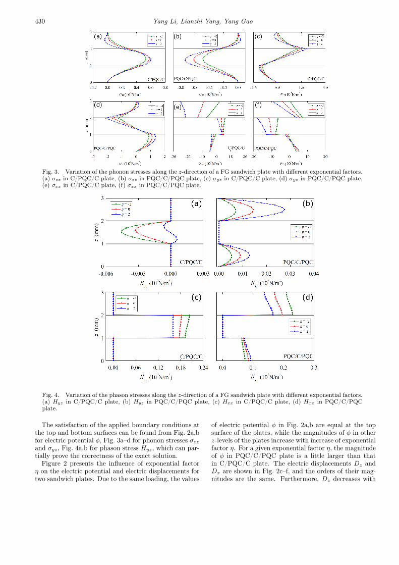
Fig. 3. Variation of the phonon stresses along the z-direction of a FG sandwich plate with different exponential factors.(a) σzz in C/PQC/C plate, (b) σzz in PQC/C/PQC plate, (c) σyz in C/PQC/C plate, (d) σyz in PQC/C/PQC plate,(e) σxx in C/PQC/C plate, (f) σxx in PQC/C/PQC plate.
Fig. 4. Variation of the phason stresses along the z-direction of a FG sandwich plate with different exponential factors.(a) Hyz in C/PQC/C plate, (b) Hyz in PQC/C/PQC plate, (c) Hxx in C/PQC/C plate, (d) Hxx in PQC/C/PQCplate.
The satisfaction of the applied boundary conditions atthe top and bottom surfaces can be found from Fig. 2a,bfor electric potential φ, Fig. 3a–d for phonon stresses σzzand σyz, Fig. 4a,b for phason stress Hyz, which can par-tially prove the correctness of the exact solution.
Figure 2 presents the influence of exponential factorη on the electric potential and electric displacements fortwo sandwich plates. Due to the same loading, the values
of electric potential φ in Fig. 2a,b are equal at the topsurface of the plates, while the magnitudes of φ in otherz-levels of the plates increase with increase of exponentialfactor η. For a given exponential factor η, the magnitudeof φ in PQC/C/PQC plate is a little larger than thatin C/PQC/C plate. The electric displacements Dz andDx are shown in Fig. 2c–f, and the orders of their mag-nitudes are the same. Furthermore, Dz decreases with
decrease of exponential factor η, and the similar trendcan be observed from Dx. Dz and Dx are easily affectedby stacking sequence.
The variation of phonon stresses along the z-directionwith different exponential factors η and stacking se-quences are shown in Fig. 3. For σzz and σyz in Fig. 3a–d,they change with exponential factor η. It can be foundthat the maximum value of σzz occurs at the middle layerof both sandwich plates, while the maximum value of σyzis observed at the interfaces of two sandwich plates. Thevalues of the in-plane stresses σxx in Fig. 3e–f are muchlarger than σzz and σyz. It is observed that the influenceof exponential factor on σxx in Fig. 3e–f becomes muchmore obvious with increase of the thickness of plates.
Figure 4 shows the variations of the phason stresses ofthe two sandwich plates with different exponential fac-tors η. It is obvious that phason stresses Hyz and Hxx inFig. 4a–d are zero in the crystal layers, because no phasonfield exists in crystal. The significant influence of expo-nential factor η on Hyz can be observed from Fig. 4a,b.The different influences of stacking sequence on the platescan be observed from Hxx in Fig. 4c, d. Furthermore,Hxx in C/PQC/C plate decreases with increase of expo-nential factor η. The similar trend of Hxx in C/PQC/Cplate can be found from the top layer in PQC/C/PQCplate, while the bottom layer in PQC/C/PQC plate fol-lows the opposite trend.
Fig. 5. Variation of the phonon and phason displacements along the z-direction of a FG sandwich plate with differentexponential factors. (a) uz in C/PQC/C plate, (b) uz in PQC/C/PQC plate, (c) ux in C/PQC/C plate, (d) ux inPQC/C/PQC plate, (e) wx in C/PQC/C plate, (f) wx in PQC/C/PQC plate.
Fig. 6. Variation of the physical quantities along the z-direction of a single layer FG plate with different phonon–phasoncoupling coefficients. (a) φ, (b) σxx, (c) σxy, (d) uz, (e) wx, (f) Hyz.
432 Yang Li, Lianzhi Yang, Yang Gao
Figure 5 shows the distribution of the phonon and pha-son displacements along the thickness direction for differ-ent exponential factors η and stacking sequences. Phonondisplacement uz in Fig. 5a, b increases with increasing ex-ponential factor η. For a given exponential factor η, thestacking sequence also has a great effect on uz. Similar tothe behavior of uz, the influence of exponential factor ηon phonon displacement ux in Fig. 5c, d is obvious. Dueto no phason field in crystal, phason displacement wx incrystal layers (Fig. 5e, f) is zero. The dependence of wxon exponential factor η is great, and the different trendsof wx with related to η are found from different layers ofthe plates. In other words, wx increases with decreasingexponential factor η at the middle layer in C/PQC/Cplate and the top layer in PQC/C/PQC plate, while theopposite trend is found for wx at the bottom layer inPQC/C/PQC plate.
In order to show the influence of phonon–phason cou-pling coefficient on the single layer FG QC plate, 0,0.2C66, 0.4C66 are taken as phonon–phason coupling co-efficient, respectively. The exponential factor is η = 2.
Figure 6 shows the variations of the physical quanti-ties with different phonon–phason coupling coefficients.Phonon–phason coupling coefficient has little effect onelectric potential φ (Fig. 6a). The in-plane phononstresses σxx (Fig. 6b), σxy (Fig. 6c) and phonon dis-placement uz (Fig. 6d) decrease slightly with increaseof phonon–phason coupling coefficient, which may be at-tributed to the good wear resistance of QCs. Phason dis-placement wx (Fig. 6e) and phason stress Hyz (Fig. 6f)are more sensitive to the phonon–phason coupling coef-ficient in comparison to displacement and stress in thephonon field.
5. Conclusions
The static deformation of a FG layered 2D PQC sim-ply supported plate, subjected to an electric potentialload on its top surface, is investigated. The exact solu-tion for FG layered 2D PQC plates is obtained in termsof the pseudo-Stroh formalism in conjunction with thepropagator matrix method. The influences of exponen-tial factor, stacking sequence and phonon–phason cou-pling coefficient on the FG plate are studied in numeri-cal examples. Numerical results show that all the phys-ical quantities in the phonon, phason, and electric fieldsare sensitive to the exponential factor and stacking se-quence. An increase of phonon–phason coupling coeffi-cient leads to an increase of phason displacements andstresses, and a slight decrease of in-plane stresses in thephonon field. The features obtained show that the intro-duction of PQCs in smart structures may enhance thecarrying capacity and the wear resistance of laminatedplates in comparison to traditional piezoelectric mate-rials. The numerical results should be useful for theanalysis, design, and numerical simulation of FG PQCplates.
Acknowledgments
The work is supported by the National Natural Sci-ence Foundation of China (Nos. 51704015 and 11472299),China Agricultural University Education Foundation(No. 1101–240001), and China Scholarship Council.
References
[1] S. Mikaeeli, B. Behjat, Compos. Struct. 154, 591(2016).
[2] J.H. Guo, J.Y. Chen, E. Pan, Int. J. Eng. Sci. 106,110 (2016).
[3] J. Sladek, V. Sladek, S. Krahulec, C.S. Chen,D.L. Young, Mech. Adv. Mater. Struct. 22, 479(2015).


![Ultimate bending capacity evaluation of laminated bamboo …kjc.njfu.edu.cn/uploads/file/20180316/20180316161646... · [10–15]. Laminated bamboo lumber columns [16–22] and the](https://static.documents.pub/doc/80x56/5f89fdeed0b2d82d3834d023/ultimate-bending-capacity-evaluation-of-laminated-bamboo-kjcnjfueducnuploadsfile2018031620180316161646.jpg)


