7/8/2010 1 Architectural Engineering firm established in 1987 Karim P. Allana, PE, RRC, RWC 104 employees in in California, Nevada and Hawaii, Washington with Expertise in: Construction Forensics; Exterior walls systems; Remedial design and engineering; Roofing; Waterproofing; Structural engineering; Mechanical engineering; Construction Introduction Case History, Downtown Sunnyvale Garage, Below Grade Waterproofing F il Failure •2 nd Largest Below Grade Structure in Northern California • 4 stories underground • 12 to 14 feet in the water table • Started Leaking as soon as dewatering pumps were turned off
Transcript
7/8/2010
1
Architectural Engineering firm established in 1987
Karim P. Allana, PE, RRC, RWC
104 employees in in California, Nevada and Hawaii, Washington with Expertise in:
Construction Forensics; Exterior walls systems; Remedial design and engineering; Roofing; Waterproofing; Structural engineering; Mechanical engineering; Construction
Introduction
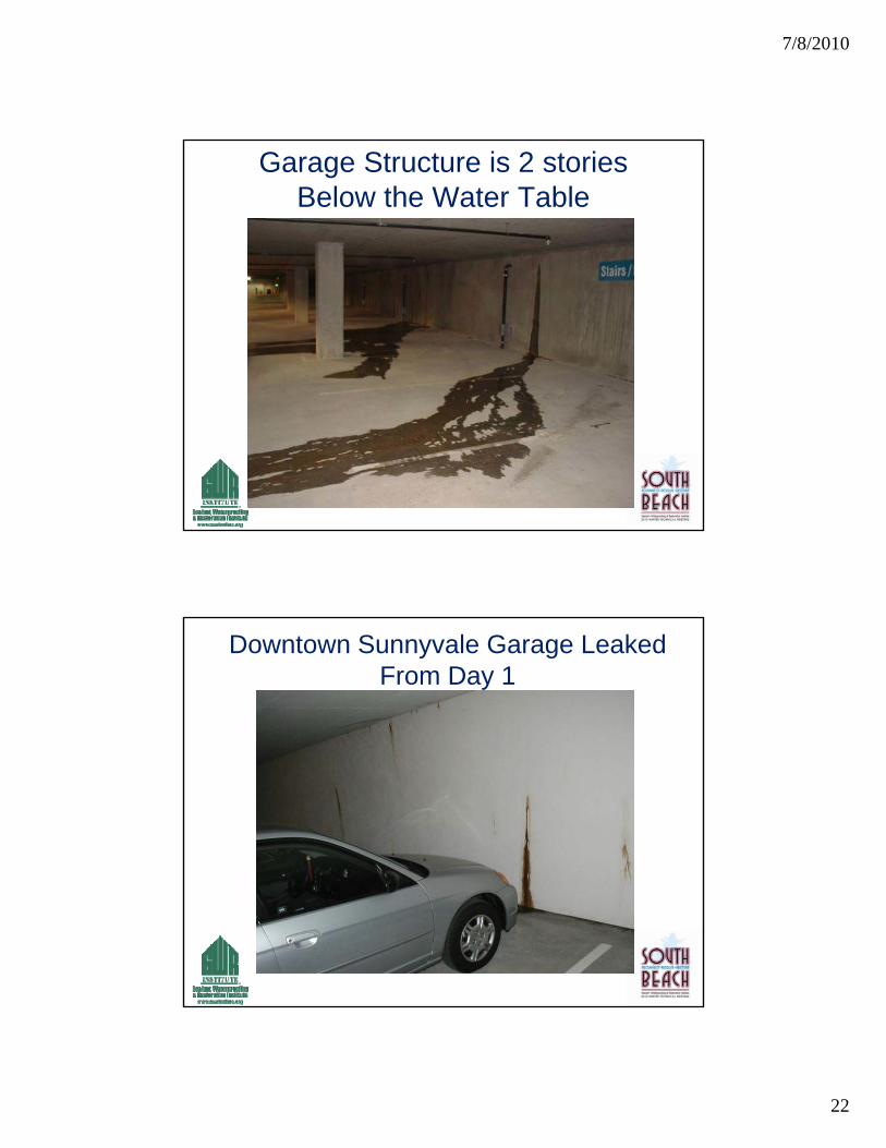
Case History, Downtown Sunnyvale Garage, Below Grade Waterproofing F ilFailure
• 2nd Largest Below Grade Structure in Northern California
• 4 stories underground• 12 to 14 feet in the water table• Started Leaking as soon as dewatering pumps were
turned off
7/8/2010
2
Introduction cont.
Focus of the presentation:• Case Study of a failed blindside y
waterproofing system• Soil retention systems and their impact
on waterproofing Failure• Sodium bentonite based waterproofing
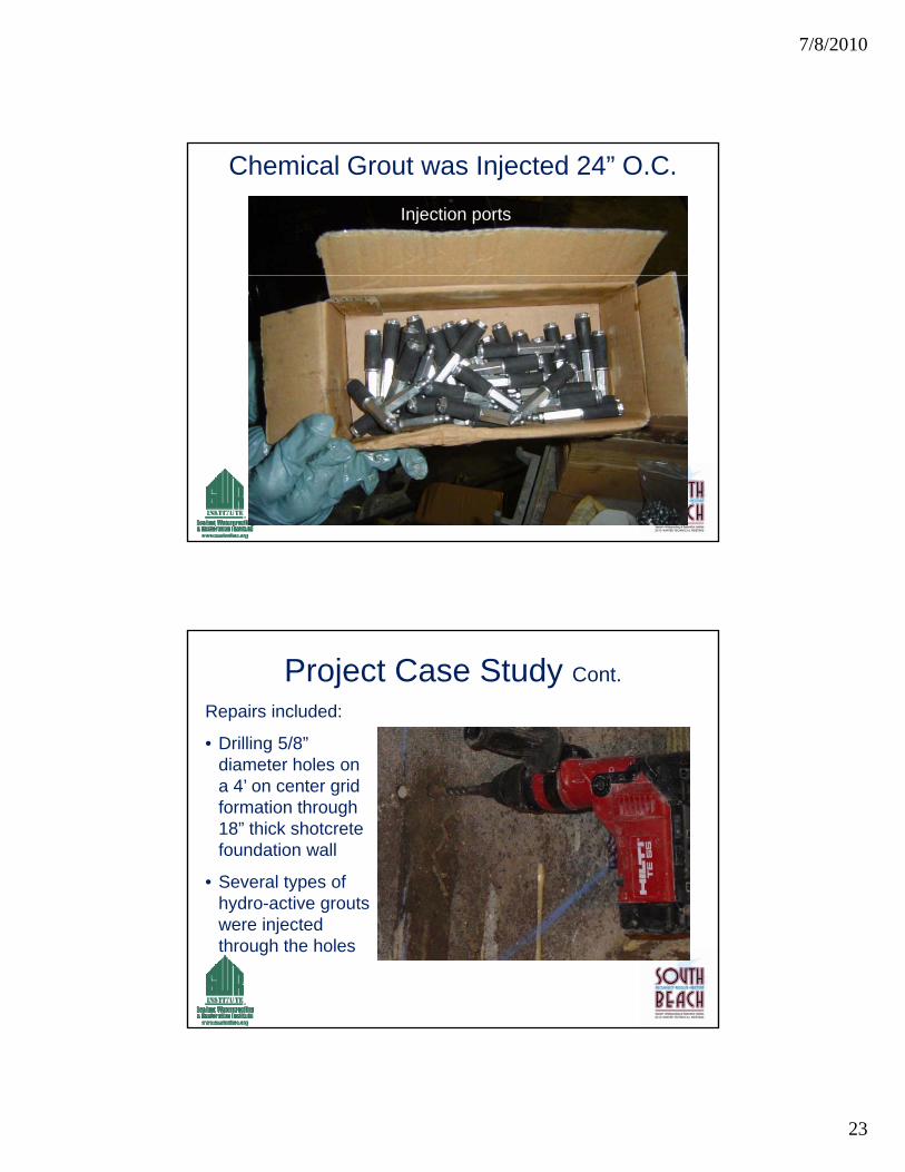
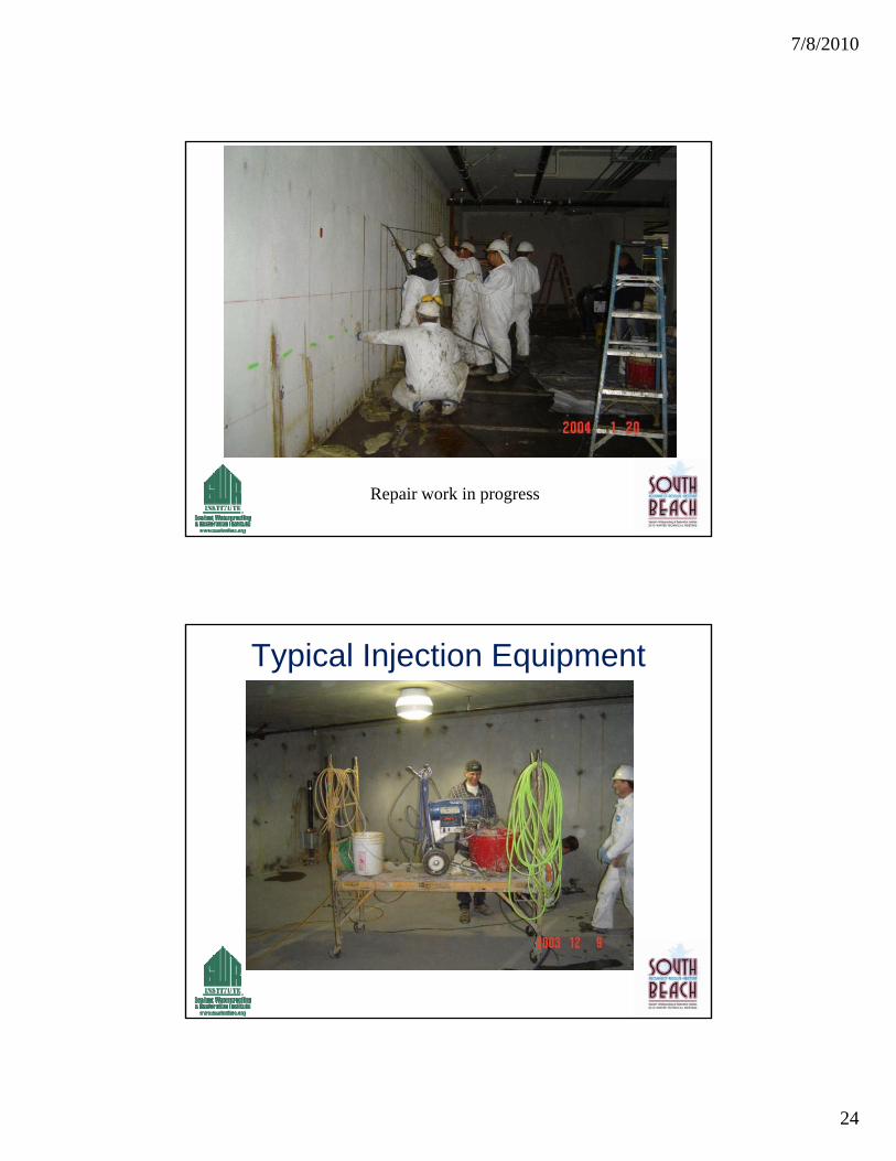
systems used in blind-side constructionsystems used in blind side construction• DeNeef Hydroactive Grout Injection
Repair. One of the largest injection repair projects in the country
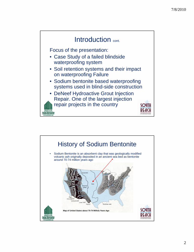
History of Sodium Bentonite• Sodium Bentonite is an absorbent clay that was geologically modified
volcanic ash originally deposited in an ancient sea bed as bentonite around 70-74 million years ago
Map of United States about 70-74 Million Years Ago
7/8/2010
3
History of Sodium Bentonite Cont.
Properties of Bentonite• An absorbent aluminum
phyllosilicate generally composed of impure claycomposed of impure clay
• Two types of Bentonite –swelling (sodium bentonite) and non-swelling (calcium bentonite)
• Sodium bentonite absorbs up to 8x’s it’s dry mass in water
• Contains exchangeable di tisodium cations
• Calcium Bentonite can be converted to Sodium Bentonite through “ion exchange”
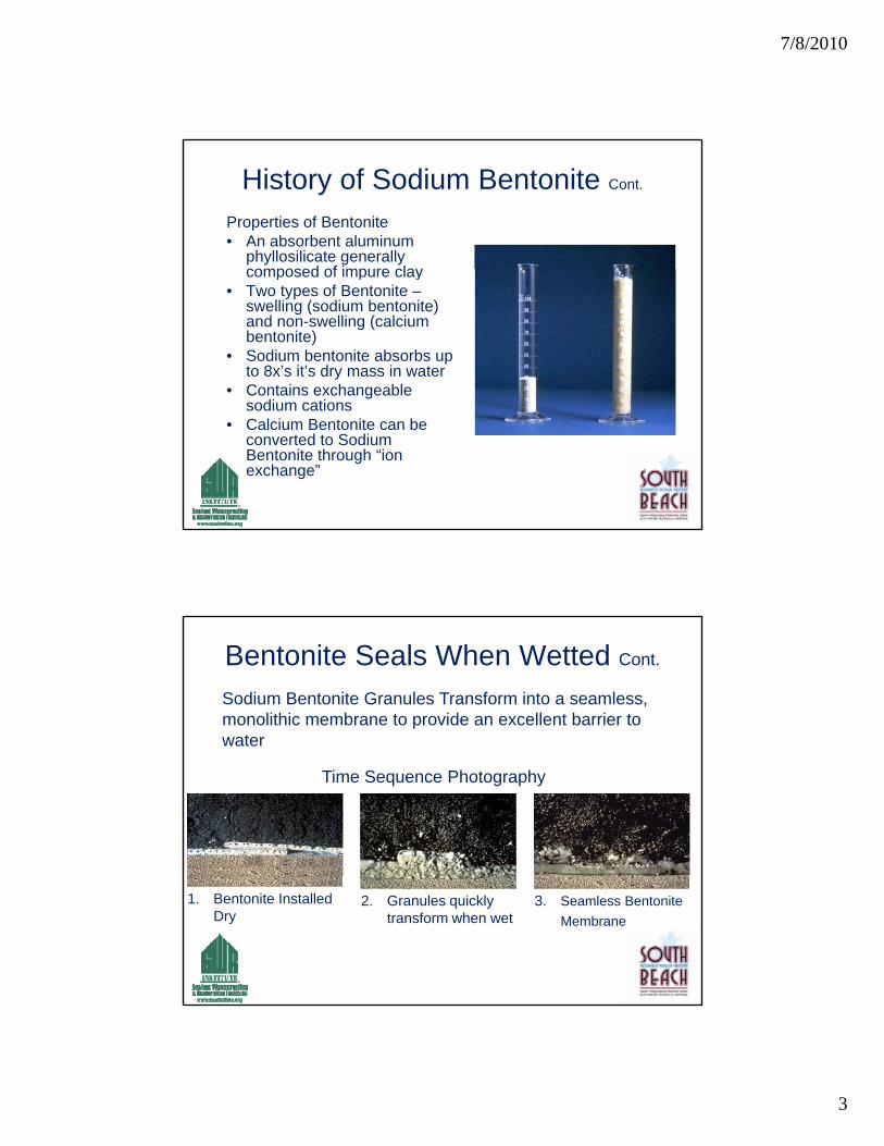
Sodium Bentonite Granules Transform into a seamless, monolithic membrane to provide an excellent barrier to water
Bentonite Seals When Wetted Cont.
water
Time Sequence Photography
1. Bentonite Installed Dry
2. Granules quickly transform when wet
3. Seamless Bentonite
Membrane
7/8/2010
4
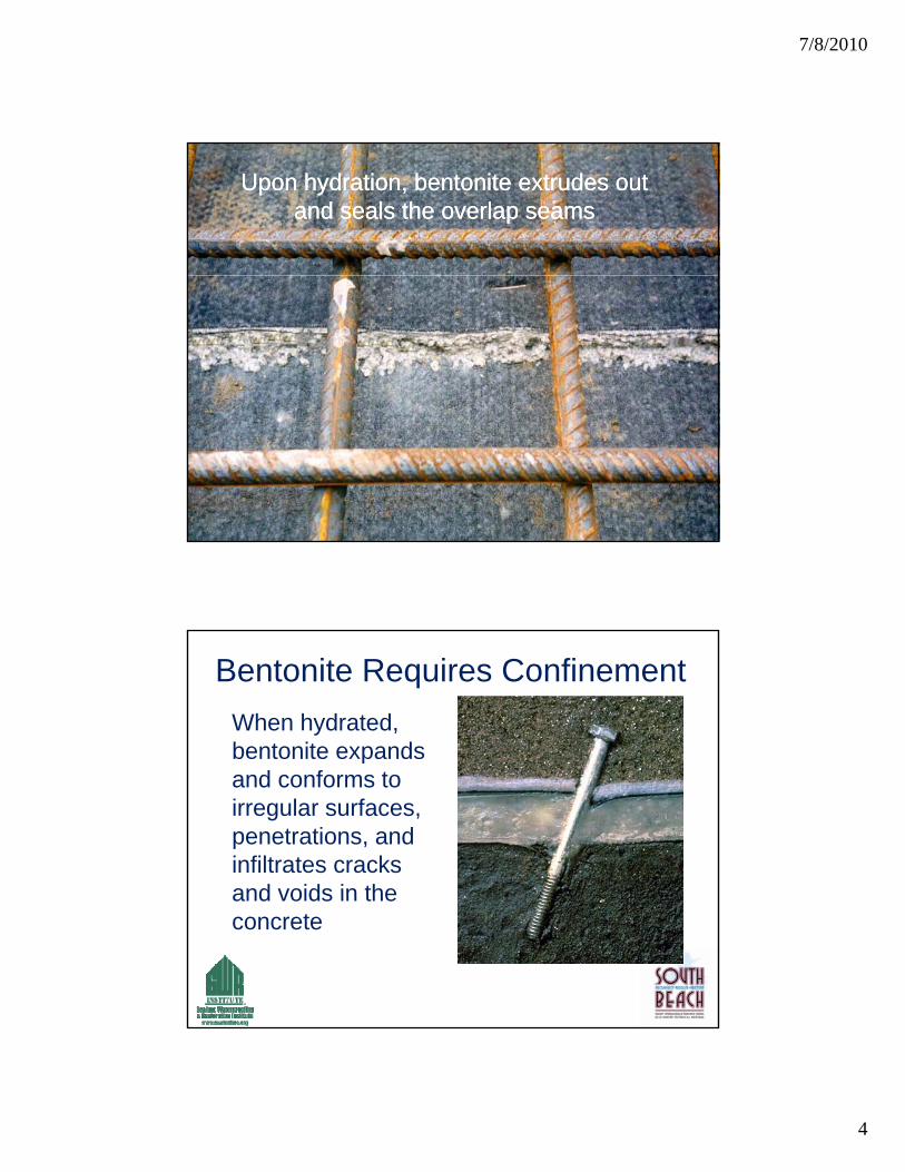
Upon hydration, bentonite extrudes out and seals the overlap seams
Upon hydration, bentonite extrudes out and seals the overlap seams
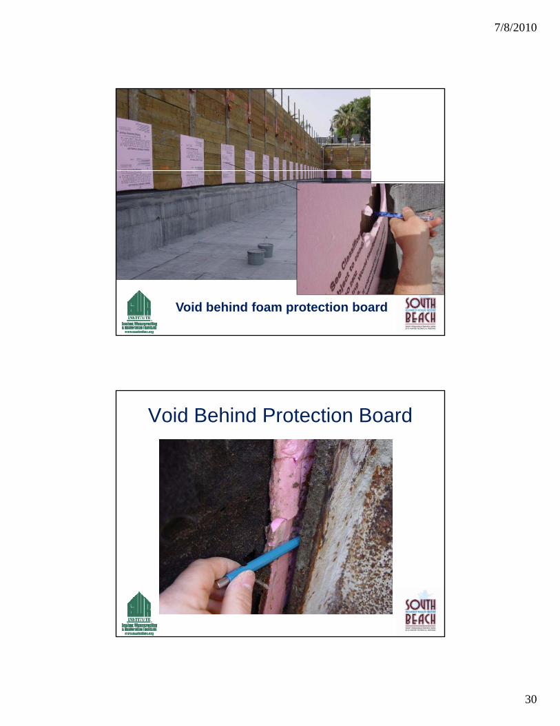
Bentonite Requires Confinement
When hydrated, bentonite expands pand conforms to irregular surfaces, penetrations, and infiltrates cracks and voids in theand voids in the concrete
7/8/2010
5
Soil Retention Systems
• Common soil retention systems include:
• Wood Lagging & Soldier Piles
• Shotcrete Lagging
• Soil Nailing
• Other systems
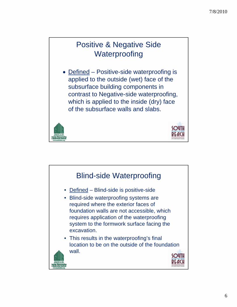
Original Bentonite Waterproofing System
7/8/2010
6
Positive & Negative Side Waterproofing
Defined – Positive-side waterproofing is Defined – Positive-side waterproofing is applied to the outside (wet) face of the subsurface building components in contrast to Negative-side waterproofing, which is applied to the inside (dry) face f th b f ll d l bof the subsurface walls and slabs.
Blind-side Waterproofing
• Defined – Blind-side is positive-side
• Blind-side waterproofing systems are p g yrequired where the exterior faces of foundation walls are not accessible, which requires application of the waterproofing system to the formwork surface facing the excavation.
• This results in the waterproofing’s final location to be on the outside of the foundation wall.
7/8/2010
7
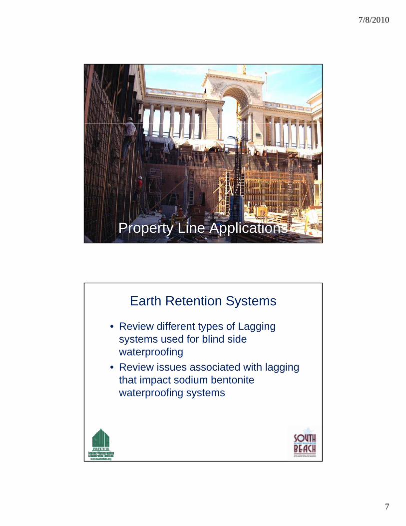
Property Line Applications
Earth Retention Systems
• Review different types of Lagging systems used for blind sidesystems used for blind side waterproofing
• Review issues associated with lagging that impact sodium bentonite waterproofing systems
7/8/2010
8
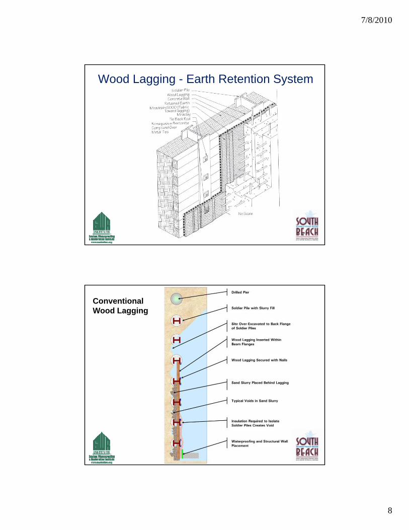
Wood Lagging - Earth Retention System
Conventional Wood Lagging
7/8/2010
9
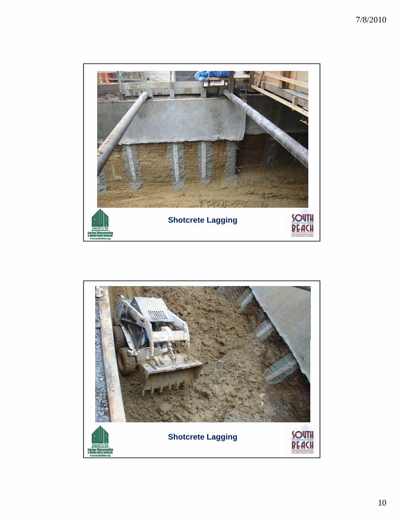
Shotcrete Lagging
• Soldier piles are predrilled at intervals along the wall's baseline The piles arealong the wall s baseline. The piles are placed in the hole and backfilled with lean-mix concrete. As the excavation in front of the wall proceeds, shotcrete lagging is installed between the soldier il i lift Ti b k h bpiles in lifts. Tieback anchors may be
installed and stressed to provide lateral restraint.
Shotcrete Lagging
7/8/2010
10
Shotcrete Lagging
Shotcrete Lagging
7/8/2010
11
Included in This Presentation
• Review 2 of the most widely used bentonite systems on the markety
• Different makeup of the systems and specific uses
• Benefits and Limitations
• Author not endorsing any product or system
Sodium Bentonite Limitations.
Inherent limitations of Bentonite HDPE• Requires compaction/confinement to be q p
effective – a minimum of 24 psf is required
• Application in brackish or slightly salt groundwater
• Standing water during construction –Standing water during construction premature hydration
7/8/2010
12
Commercial Bentonite/HDPE Products
Product Reviewed :
• Tremco - Paraseal LG– Multi-layer sheet membrane waterproofing system
• Multi-layer (3-layer) sheet membrane waterproofing systemg y
1. Consists of self-sealing, expandable layer of granular bentonite
2. Bentonite layer is laminated to HDPE sheet3. Covered with a protective layer of spun
polypropylene
• Controlled thicknesses of 170 mils to 200 mils
• Designed for blind-side installations
7/8/2010
13
Tremco – Paraseal LG Cont.
Blindside application
• Applied before walls are poured• Applied before walls are poured
• Designed to resist damage from:– Some exposure to inclement weather
– Normal concrete pours
– Direct installation of shotcrete
• Can be used in hydrostatic head conditions
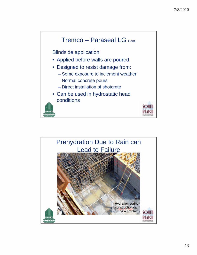
Prehydration Due to Rain can Lead to Failure
Hydration during Hydration during construction can construction can
be a problembe a problem
7/8/2010
14
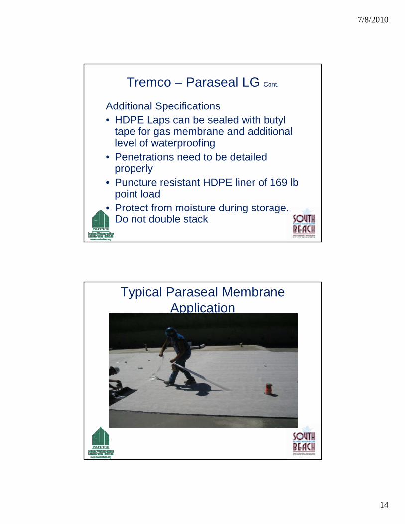
Tremco – Paraseal LG Cont.
Additional Specifications• HDPE Laps can be sealed with butylHDPE Laps can be sealed with butyl
tape for gas membrane and additional level of waterproofing
• Penetrations need to be detailed properly
• Puncture resistant HDPE liner of 169 lb• Puncture resistant HDPE liner of 169 lb point load
• Protect from moisture during storage. Do not double stack
Typical Paraseal Membrane Application
7/8/2010
15
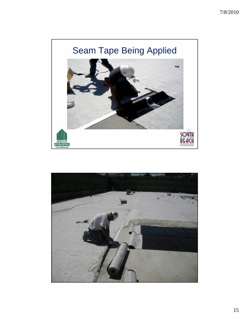
Seam Tape Being Applied
7/8/2010
16
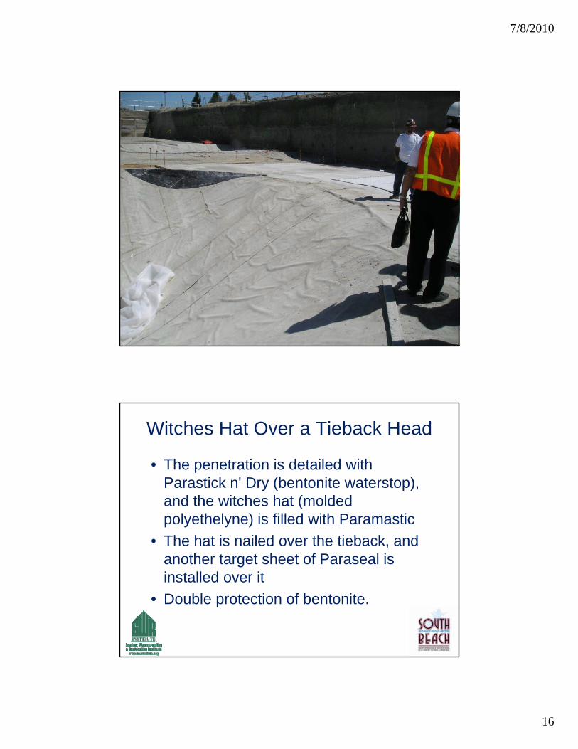
Witches Hat Over a Tieback Head
• The penetration is detailed with Parastick n' Dry (bentonite waterstop),Parastick n Dry (bentonite waterstop), and the witches hat (molded polyethelyne) is filled with Paramastic
• The hat is nailed over the tieback, and another target sheet of Paraseal is i t ll d itinstalled over it
• Double protection of bentonite.
7/8/2010
17
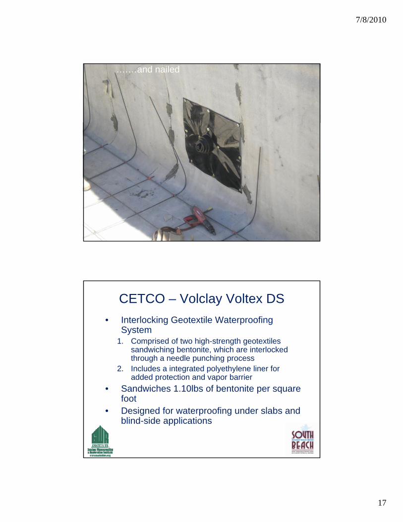
….…and nailed
CETCO – Volclay Voltex DS
• Interlocking Geotextile Waterproofing System
1 Comprised of two high strength geotextiles1. Comprised of two high-strength geotextiles sandwiching bentonite, which are interlocked through a needle punching process
2. Includes a integrated polyethylene liner for added protection and vapor barrier
• Sandwiches 1.10lbs of bentonite per square footfoot
• Designed for waterproofing under slabs and blind-side applications
7/8/2010
18
CETCO – Volclay Voltex DS Cont.
• Unique Design Feature
• Concrete/shotcrete clings to geotextileConcrete/shotcrete clings to geotextile fibers
• Allows waterproofing panels to stay in place, against concrete and shotcrete walls
• Designed only for below-grade waterproofing applications
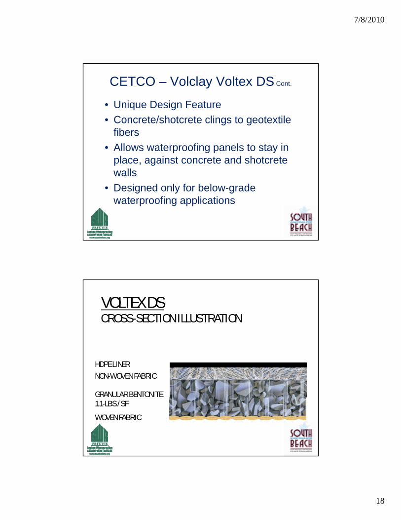
VOLTEX DSCROSS-SECTION ILLUSTRATION
HDPE LINERNON-WOVEN FABRIC
GRANULAR BENTONITE1.1-LBS./SFWOVEN FABRIC
7/8/2010
19
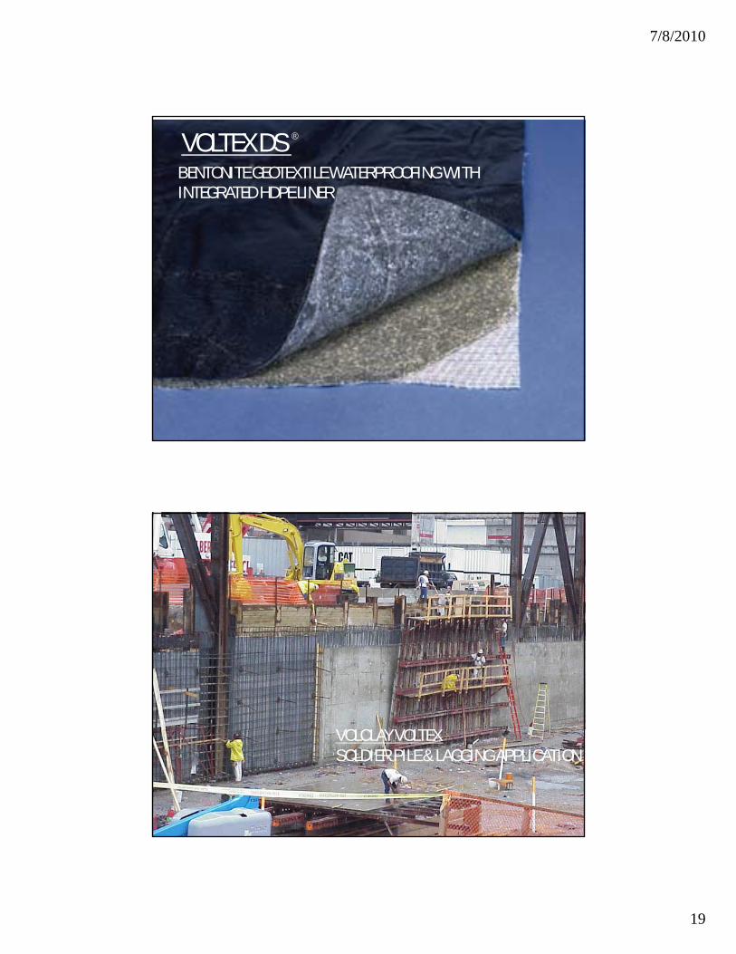
VOLTEX DS ®
BENTONITE GEOTEXTILE WATERPROOFING WITH INTEGRATED HDPE LINER