BERNOULLI AND ENERGY EQUATIONS T his chapter deals with two equations commonly used in fluid mechan- ics: the Bernoulli equation and the energy equation. The Bernoulli equa- tion is concerned with the conservation of kinetic, potential, and flow energies of a fluid stream, and their conversion to each other in regions of flow where net viscous forces are negligible, and where other restrictive con- ditions apply. The energy equation is a statement of the conservation of en- ergy principle and is applicable under all conditions. In fluid mechanics, it is found to be convenient to separate mechanical energy from thermal energy and to consider the conversion of mechanical energy to thermal energy as a re- sult of frictional effects as mechanical energy loss. Then the energy equation is usually expressed as the conservation of mechanical energy. We start this chapter with a discussion of various forms of mechanical en- ergy and the efficiency of mechanical work devices such as pumps and tur- bines. Then we derive the Bernoulli equation by applying Newton’s second law to a fluid element along a streamline and demonstrate its use in a variety of applications. We continue with the development of the energy equation in a form suitable for use in fluid mechanics and introduce the concept of head loss. Finally, we apply the energy equation to various engineering systems. 519 CHAPTER 12 CONTENTS 12–1 Mechanical Energy and Efficiency 520 12–2 The Bernoulli Equation 525 12–3 Applications of the Bernoulli Equation 534 12–4 Energy Analysis of Steady-Flow Systems 541 Summary 549 References and Suggested Reading 551 Problems 551
Transcript
B E R N O U L L I A N D E N E R G YE Q U AT I O N S
This chapter deals with two equations commonly used in fluid mechan-ics: the Bernoulli equation and the energy equation. The Bernoulli equa-tion is concerned with the conservation of kinetic, potential, and flow
energies of a fluid stream, and their conversion to each other in regions offlow where net viscous forces are negligible, and where other restrictive con-ditions apply. The energy equation is a statement of the conservation of en-ergy principle and is applicable under all conditions. In fluid mechanics, it isfound to be convenient to separate mechanical energy from thermal energyand to consider the conversion of mechanical energy to thermal energy as a re-sult of frictional effects as mechanical energy loss. Then the energy equationis usually expressed as the conservation of mechanical energy.
We start this chapter with a discussion of various forms of mechanical en-ergy and the efficiency of mechanical work devices such as pumps and tur-bines. Then we derive the Bernoulli equation by applying Newton’s secondlaw to a fluid element along a streamline and demonstrate its use in a varietyof applications. We continue with the development of the energy equation ina form suitable for use in fluid mechanics and introduce the concept of headloss. Finally, we apply the energy equation to various engineering systems.
519
CHAPTER
12CONTENTS
12–1 Mechanical Energy andEfficiency 520
12–2 The Bernoulli Equation 525
12–3 Applications of the BernoulliEquation 534
12–4 Energy Analysis of Steady-FlowSystems 541
Summary 549
References and SuggestedReading 551
Problems 551
12–1 MECHANICAL ENERGY AND EFFICIENCYMost fluid systems are designed to transport a fluid from one location toanother at a specified flow rate, velocity, and elevation difference, and thesystem may generate mechanical work in a turbine or it may consume me-chanical work in a pump or fan during this process. These systems do notinvolve the conversion of nuclear, chemical, or thermal energy to mechanicalenergy. Also, they do not involve any heat transfer in any significant amount,and they operate essentially at constant temperature. Such systems can be an-alyzed conveniently by considering the mechanical forms of energy onlyand the frictional effects that cause the mechanical energy to be lost (i.e., tobe converted to thermal energy that usually cannot be used for any usefulpurpose).
The mechanical energy can be defined as the form of energy that can beconverted to mechanical work completely and directly by a mechanical devicesuch as an ideal turbine. Kinetic and potential energies are the familiar formsof mechanical energy. Thermal energy is not mechanical energy, however,since it cannot be converted to work directly and completely (the second lawof thermodynamics).
A pump transfers mechanical energy to a fluid by raising its pressure, and aturbine extracts mechanical energy from a fluid by dropping its pressure.Therefore, the pressure of a flowing fluid is also associated with its mechani-cal energy. In fact, the pressure unit Pa is equivalent to Pa � N/m2 � N � m/m3
� J/m3, and the product Pυ or its equivalent P/r has the unit J/kg, which is en-ergy unit per unit mass. Note that pressure itself is not a form of energy. But apressure force acting on a fluid through a distance produces work, called flowwork, in the amount of P/r per unit mass. Flow work is expressed in terms offluid properties, and it is found convenient to view it as part of the energy ofa flowing fluid, and call it flow energy. Therefore, the mechanical energy of aflowing fluid can be expressed on a unit mass basis as (Fig. 12–1).
where P/r is the flow energy, is the kinetic energy, and gz is the poten-tial energy of the fluid per unit mass. Then the mechanical energy change of afluid during incompressible flow becomes
(12–1)
Therefore, the mechanical energy of a fluid does not change during flow if itspressure, density, velocity, and elevation remain constant. In the absence ofany losses, the mechanical energy change represents the mechanical worksupplied to the fluid (if ∆emech � 0) or extracted from the fluid (if ∆emech � 0).
Consider a container of height h filled with water, as shown in Fig. 12–2,with reference level selected at the bottom surface. The gage pressure and thepotential energy per unit mass are PA � 0 and peA � gh at point A at the freesurface, and PB � rgh and peB � 0 at point B at the bottom of the container.An ideal hydraulic turbine would produce the same work per unit masswturbine � gh whether it receives water (or any other fluid with constantdensity) from the top or from the bottom of the container. Note that we are
�emech �P2 � P1r �
�22 � �2
1
2� g(z2 � z1) (kJ/kg)
�2/2
emech �Pr�
� 2
2� gz
■
520FUNDAMENTALS OF THERMAL-FLUID SCIENCES
h = 10 m
m = 2 kg/s
Atmosphere
0
z
= m
= (2 kg/s)(9.81 m/s2)(10 m)
= 196 W
Wmax
W
= m = mghP 1 – P atm–––––––––ρ
gh ––– ρ
ρ
·
· · · ·
·
1
FIGURE 12–1In the absence of any changes in flowvelocity and elevation, the powerproduced by a hydraulic turbine isproportional to the pressure drop ofwater across the turbine.
also assuming ideal flow (no irreversible losses) through the pipe leading fromthe tank to the turbine. Therefore, the total mechanical energy of water at thebottom is equivalent to that at the top.
The transfer of mechanical energy is usually accomplished by a rotatingshaft, and thus mechanical work is often referred to as shaft work. A pump ora fan receives shaft work (usually from an electric motor) and transfers it tothe fluid as mechanical energy (less frictional losses). A turbine, on the otherhand, converts the mechanical energy of a fluid to shaft work. In the absenceof any irreversibilities such as friction, mechanical energy can be convertedentirely from one mechanical form to another, and the mechanical efficiencyof a device or process can be defined as (Fig. 12–3).
hmech � (12–2)
A conversion efficiency of less than 100 percent indicates that conversion isless than perfect and some losses have occurred during conversion. A me-chanical efficiency of 97 percent indicates that 3 percent of the mechanical en-ergy input is converted to thermal energy as a result of frictional heating, andthis will manifest itself as a slight rise in the temperature of the fluid.
In fluid systems, we are usually interested in increasing the pressure, veloc-ity, and/or elevation of a fluid. This is done by supplying mechanical energyto the fluid by a pump, a fan, or a compressor (we will refer to all of them aspumps). Or we are interested in the reverse process of extracting mechanicalenergy from a fluid by a turbine, and producing mechanical power in the formof a rotating shaft that can drive a generator or any other rotary device. Thedegree of perfection of the conversion process between the mechanical worksupplied or extracted and the mechanical energy of the fluid is expressed bythe pump efficiency and turbine efficiency, defined as
hpump � (12–3)
where � � mech, fluid � mech, out � mech, in is the rate of increase in themechanical energy of the fluid, which is equivalent to the useful pumpingpower supplied to the fluid, and
hturbine � (12–4)Mechanical engery output
Mechanical energy decrease of the fluid�
�Wshaft, out
�� �E mech, fluid�
�
�Wturbine�
Wturbine, e
�E
�E
�E�Wpump, u
Mechanical energy increase of the fluidMechanical energy input
�
�W pump, u
�Wpump
Mechanical energy outputMechanical energy input
�Emech, out
Emech, in� 1 �
Emech, loss
Emech, in
CHAPTER 12521
FIGURE 12–2The mechanical energy of water atthe bottom of a lake is equal to the
mechanical energy at any depthincluding the free surface of the lake.m
0
zh pe = gh
P = 0
P = ghρpe = 0
A
B
m·
Wmax = mgh· · Wmax = mgh
· ·
·
FIGURE 12–3The mechanical efficiency of a
fan is the ratio of the kinetic energyof air at the fan exit to themechanical power input.
m = 0.25 kg/s
Fan
50 W ·
1 2
= 0, 1 = 12 m/s= z2z1= P2P1
=
=
= 0.72
ηmech, fan = ∆Emech, fluid––––––––––Wshaft, in
(0.25 kg/s)(12 m/s)2/2–––––––––––––––––
50 W
·
· m�2
2/2–––––––Wshaft, in
··
� 2�
where �� mech, fluid� � mech, in � mech, out is the rate of decrease in the me-chanical energy of the fluid, which is equivalent to the mechanical power ex-tracted from the fluid by the turbine , and we used the absolute valuesign to avoid negative values for efficiencies. A pump or turbine efficiency of100 percent indicates perfect conversion between the shaft work and the me-chanical energy of the fluid, and this value can be approached (but never at-tained) as the frictional effects are minimized.
The mechanical efficiency should not be confused with the motor effi-ciency and the generator efficiency, which are defined as
Motor: hmotor � (12–5)
and
Generator: hgenerator � (12–6)
A pump is usually packaged together with its motor, and a hydraulic turbinewith its generator. Therefore, we are usually interested in the combined oroverall efficiency of pump/motor and turbine/generator combinations(Fig. 12–4), which are defined as
hpump-motor � hpump hmotor � (12–7)
and
hturbine-gen � hturbine hgenerator � (12–8)
All the efficiencies just defined range between 0 and 100 percent. The lowerlimit of 0 percent corresponds to the conversion of the entire mechanical orelectrical energy input to thermal energy, and the device in this case functionslike a resistance heater. The upper limit of 100 percent corresponds to the caseof perfect conversion with no friction or other irreversibilities, and thus noconversion of mechanical or electrical energy to thermal energy.
�Welect, out�
Wturbine, e
�
�Welect, out
�� �Emech, fluid�
�W pump, u
�Welect, in
��
�E mech, fluid
�Welect, in
Electrical power outputMechanical power input
�
�Welect, out�
Wshaft, in
Mechanical power outputElectrical power input
�
�Wshaft, out�
Welect, in
�Wturbine, e
�E
�E
�E
522FUNDAMENTALS OF THERMAL-FLUID SCIENCES
EXAMPLE 12–1 Performance of a Hydraulic Turbine-Generator
The water in a large lake is to be used to generate electricity by installing ahydraulic turbine-generator at a location where the depth of the water is 50 m(Fig. 12–5). Water is to be supplied at a rate of 5000 kg/s. If the electric powergenerated is measured to be 1862 kW and the generator efficiency is 95 per-cent, determine (a) the overall efficiency of the turbine-generator, (b) the me-chanical efficiency of the turbine, and (c) the shaft power supplied by theturbine to the generator.
SOLUTION A hydraulic turbine-generator is to generate electricity from thewater of a lake. The overall efficiency, the turbine efficiency, and the shaftpower are to be determined.
FIGURE 12–4The overall efficiency of a turbine-generator is the product of theefficiency of the turbine and theefficiency of the generator, andrepresents the fraction of themechanical energy of the fluidconverted to electrical energy.
Generator
=
= 0.75 × 0.97 = 0.73
Turbine
turbine-gen
= 0.75 turbine = 0.97 generatorη η
turbine generatorη η η
CHAPTER 12523
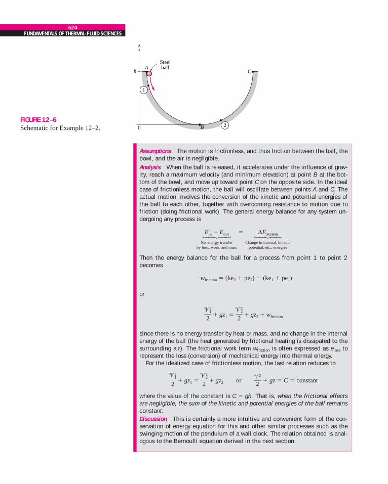
EXAMPLE 12–2 Conservation of Energy for an OscillatingSteel Ball
The motion of a steel ball in a hemispherical bowl of radius h shown in Fig.12–6 is to be analyzed. The ball is initially held at the highest location at pointA, and then it is released. Obtain relations for the conservation of energy of theball for the cases of frictionless and actual motions.
SOLUTION A steel ball is released in a bowl. Relations for the energy balanceare to be obtained.
GeneratorTurbine
1862 kW
m = 5000 kg/s
h = 50 m
·
Lake = 0.95 generatorη
FIGURE 12–5Schematic for Example 12–1.
Assumptions 1 The elevation of the lake remains constant. 2 The mechanicalenergy of water at the turbine exit is negligible.Properties The density of water can be taken to be r � 1000 kg/m3.Analysis (a) We take the bottom of the lake as the reference level for conve-nience. Then kinetic and potential energies of water are zero, and the change inits mechanical energy per unit mass becomes
emech, in � emech, out � � 0 � gh � (9.81 m/s2)(50 m) � 0.491 kJ/kg
Then the rate at which mechanical energy is supplied to the turbine by the fluidand the overall efficiency become
Discussion Note that the lake supplies 2455 kW of mechanical energy to theturbine, which converts 1964 kW of it to shaft work that drives the generator,which generates 1862 kW of electric power. There are irreversible lossesthrough each component.
�E
�W
hturbine�gen
hgenerator�
0.760.95
�Welect, out
�� �Emech, fluid�
�1862 kW2455 kW
�m�E
a 1 kJ/kg
1000 m2/s2bPr
524FUNDAMENTALS OF THERMAL-FLUID SCIENCES
FIGURE 12–6Schematic for Example 12–2.
Steelball
0
z
hA
B
C
1
2
Assumptions The motion is frictionless, and thus friction between the ball, thebowl, and the air is negligible.Analysis When the ball is released, it accelerates under the influence of grav-ity, reach a maximum velocity (and minimum elevation) at point B at the bot-tom of the bowl, and move up toward point C on the opposite side. In the idealcase of frictionless motion, the ball will oscillate between points A and C. Theactual motion involves the conversion of the kinetic and potential energies ofthe ball to each other, together with overcoming resistance to motion due tofriction (doing frictional work). The general energy balance for any system un-dergoing any process is
Then the energy balance for the ball for a process from point 1 to point 2becomes
�wfriction � (ke2 � pe2) � (ke1 � pe1)
or
since there is no energy transfer by heat or mass, and no change in the internalenergy of the ball (the heat generated by frictional heating is dissipated to thesurrounding air). The frictional work term wfriction is often expressed as eloss torepresent the loss (conversion) of mechanical energy into thermal energy.
For the idealized case of frictionless motion, the last relation reduces to
or � gz � C � constant
where the value of the constant is C � gh. That is, when the frictional effectsare negligible, the sum of the kinetic and potential energies of the ball remainsconstant.Discussion This is certainly a more intuitive and convenient form of the con-servation of energy equation for this and other similar processes such as theswinging motion of the pendulum of a wall clock. The relation obtained is anal-ogous to the Bernoulli equation derived in the next section.
�2
2�2
1
2� gz1 �
�22
2� gz2
�21
2� gz1 �
�22
2� gz2 � wfriction
Ein � Eout14243Net energy transfer
by heat, work, and mass
� �Esystem14243Change in internal, kinetic,
potential, etc., energies
Most processes encountered in practice involve only certain forms of energy,and in such cases it is more convenient to work with the simplified versions ofthe energy balance. For systems that involve only mechanical forms of energyand its transfer as shaft work, the conservation of energy principle can be ex-pressed conveniently as
Emech, in � Emech, out � �Emech, system � Emech, loss (12–9)
where Emech, loss represents the conversion of mechanical energy to thermal en-ergy due to irreversibilities such as friction. For a system in steady operation, the mechanical energy balance becomes mech, in � mech, out � mech, loss (Fig. 12–7).
12–2 THE BERNOULLI EQUATIONThe Bernoulli equation is an approximate relation between pressure, veloc-ity, and elevation, and is valid in regions of steady, incompressible flow wherenet frictional forces are negligible (Fig. 12–8). Despite its simplicity, it hasproven to be a very powerful tool in fluid mechanics. In this section, we de-rive the Bernoulli equation by applying the conservation of linear momentumprinciple, and we demonstrate both its usefulness and its limitations.
The key approximation in the derivation of the Bernoulli equation is thatviscous effects are negligibly small compared to inertial, gravitational, andpressure effects. Since all fluids have viscosity (there is no such thing as an“inviscid fluid”), this approximation cannot be valid for an entire flow field ofpractical interest. In other words, we cannot apply the Bernoulli equationeverywhere in a flow, no matter how small the fluid’s viscosity. However, itturns out that the approximation is reasonable in certain regions of many prac-tical flows. We refer to such regions as inviscid regions of flow, and we stressthat they are not regions where the fluid itself is inviscid or frictionless, butrather they are regions where net viscous or frictional forces are negligiblysmall compared to other forces acting on fluid particles.
Care must be exercised when applying the Bernoulli equation since it is anapproximation that applies only to inviscid regions of flow. In general, fric-tional effects are always important very close to solid walls (boundary layers)and directly downstream of bodies (wakes). Thus, the Bernoulli approxima-tion is typically useful in flow regions outside of boundary layers and wakes,where the fluid motion is governed by the combined effects of pressure andgravity forces.
The motion of a particle and the path it follows are described by the veloc-ity vector as a function of time and space coordinates and the initial positionof the particle. When the flow is steady (no change with time at a specified lo-cation), all particles that pass through the same point follow the same path(which is the streamline), and the velocity vectors remain tangent to the pathat every point.
Acceleration of a Fluid ParticleOften it is convenient to describe the motion of a particle in terms of its dis-tance s from the origin together with the radius of curvature along the stream-line. The velocity of the particle is related to the distance by � � ds/dt, whichmay vary along the streamline. In two-dimensional flow, the acceleration canbe decomposed into two components: streamwise acceleration as along the
■
�E
�E
�E
CHAPTER 12525
FIGURE 12–7Most fluid flow problems involve
mechanical forms of energy only, andsuch problems are conveniently solvedby using a mechanical energy balance.
1 = 2z2 = z1 + h
P1 ≅ P2 ≅ Patm
Emech, in = Emech, out + Emech, loss· · ·
·Wpump + mgz1 = mgz2 + Emech, loss· · ·
·Wpump = mgh + Emech, loss· ·
h
2
Steady flow
1
� �
Wpump·
Bernoulli equation valid
Bernoulli equation not valid
FIGURE 12–8The Bernoulli equation is an
approximate equation that is validonly in inviscid regions of flow where
net viscous forces are negligibly smallcompared to inertial, gravitational, or
pressure forces. Such regions occuroutside of boundary layers and wakes.
streamline and normal acceleration an in the direction normal to the stream-line, which is given as an � �2/R. Note that streamwise acceleration is due toa change in speed along a streamline, and normal acceleration is due to achange in direction. For particles that move along a straight path, an � 0 sincethe radius of curvature is infinity and thus there is no change in direction. TheBernoulli equation results from a force balance along a streamline.
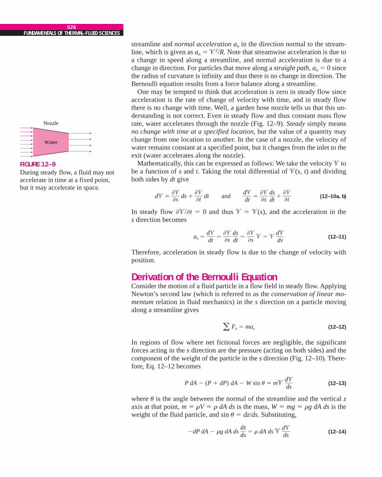
One may be tempted to think that acceleration is zero in steady flow sinceacceleration is the rate of change of velocity with time, and in steady flowthere is no change with time. Well, a garden hose nozzle tells us that this un-derstanding is not correct. Even in steady flow and thus constant mass flowrate, water accelerates through the nozzle (Fig. 12–9). Steady simply meansno change with time at a specified location, but the value of a quantity maychange from one location to another. In the case of a nozzle, the velocity ofwater remains constant at a specified point, but it changes from the inlet to theexit (water accelerates along the nozzle).
Mathematically, this can be expressed as follows: We take the velocity � tobe a function of s and t. Taking the total differential of �(s, t) and dividingboth sides by dt give
(12–10a, b)
In steady flow ��/�t � 0 and thus � � �(s), and the acceleration in the s direction becomes
(12–11)
Therefore, acceleration in steady flow is due to the change of velocity withposition.
Derivation of the Bernoulli EquationConsider the motion of a fluid particle in a flow field in steady flow. ApplyingNewton’s second law (which is referred to as the conservation of linear mo-mentum relation in fluid mechanics) in the s direction on a particle movingalong a streamline gives
Fs � mas (12–12)
In regions of flow where net fictional forces are negligible, the significantforces acting in the s direction are the pressure (acting on both sides) and thecomponent of the weight of the particle in the s direction (Fig. 12–10). There-fore, Eq. 12–12 becomes
P dA � (P � dP) dA � W sin u � m� (12–13)
where u is the angle between the normal of the streamline and the vertical zaxis at that point, m � rV � r dA ds is the mass, W � mg � rg dA ds is theweight of the fluid particle, and sin u � dz/ds. Substituting,
�dP dA � rg dA ds � r dA ds � (12–14)d�ds
dzds
d�ds
�
as �d�dt
����s
dsdt
����s � � �
d�ds
d� ����s ds �
���t dt and d�
dt�
���s
dsdt
����t
526FUNDAMENTALS OF THERMAL-FLUID SCIENCES
FIGURE 12–9During steady flow, a fluid may notaccelerate in time at a fixed point,but it may accelerate in space.
Water
Nozzle
Canceling dA from each term and simplifying,
�dP � rg dz � r� d� (12–15)
Noting that � d � � d(�2) and dividing each term by r gives
� d(�2) � g dz � 0 (12–16)
Integrating (Fig. 12–11),
Steady flow: � gz � constant (along a streamline) (12–17)
since the last two terms are exact differentials. In the case of incompressibleflow, the first term also becomes an exact differential, and its integration gives
This is the famous Bernoulli equation, which is commonly used in fluid me-chanics for steady, incompressible flow in inviscid regions of flow. The valueof the constant can be evaluated at any point on the streamline where the pres-sure, density, velocity, and elevation are known. The Bernoulli equation canalso be written between any two points on the same streamline as
The Bernoulli equation is obtained from the conservation of momentum fora fluid particle moving along a streamline. It can also be obtained from thefirst law of thermodynamics applied to a steady-flow system, as shown later inthis chapter.
The Bernoulli equation was first stated verbally in a textbook by DanielBernoulli in 1738 and was derived later by Leonhard Euler in 1755. We recog-nize �2/2 as kinetic energy, gz as potential energy, and P/r as flow energy perunit mass. Therefore, the Bernoulli equation can be viewed as an expression ofmechanical energy balance and can be stated as follows (Fig. 12–12):
P2r �
�22
2P1r �
�21
2
Pr�
�2
2� gz
� dPr �
�2
2
12
dPr
12
CHAPTER 12527
FIGURE 12–10The forces acting on a
fluid particle along a streamline.
z
x
W
sn
PdA
(P + dP)dA
Streamline
dx
dzds
ds
θ
θ
FIGURE 12–11The Bernoulli equation is derived
assuming incompressible flow, andthus it should not be used for flows
with significant compressibilityeffects.
General:(Steady flow)
Incompressible flow ( = constant):ρ
∫ –– + + gz = constantdPρ ––
2
2
–– + + gz = constantPρ ––
2
2
�
�
FIGURE 12–12The Bernoulli equation states that
the sum of the kinetic, potential, andflow energies of a fluid particle is
constant along a streamlineduring steady flow.
–– + + gz = constant
Flowenergy
Pρ ––
2
2
Potentialenergy
Kineticenergy
�
The sum of the kinetic, potential, and flow energies of a fluid particle isconstant along a streamline during steady flow when the compressibilityand frictional effects are negligible.
The kinetic, potential, and flow energies are the mechanical forms ofenergy, as discussed earlier, and the Bernoulli equation can be viewed asthe “conservation of mechanical energy principle.” This is equivalent to thegeneral conservation of energy principle for systems that do not involve anyconversion of mechanical energy and thermal energy to each other, and thusthe mechanical energy and thermal energy are conserved separately. TheBernoulli equation states that during steady, incompressible flow with negli-gible friction, the various forms of mechanical energy are converted to eachother, but their sum remains constant. In other words, there is no dissipationof mechanical energy during such flows since there is no friction that convertsmechanical energy to sensible thermal (internal) energy.
Recall that energy is transferred to a system as work when a force is appliedto a system through a distance. In the light of Newton’s second law of motion,the Bernoulli equation can also be viewed as the work done by the pressureand gravity forces on the fluid particle is equal to the increase in the kineticenergy of the particle.
Despite the highly restrictive approximations used in its derivation, theBernoulli equation is commonly used in practice since a variety of practicalfluid flow problems can be analyzed to reasonable accuracy with it. This is be-cause many flows of practical engineering interest are steady (or at leaststeady in the mean), compressibility effects are relatively small, and net fric-tional forces are negligible in regions of interest in the flow.
Unsteady Compressible FlowSimilarly, using both terms in the acceleration expression (Eq. 12–10), it canbe shown that the Bernoulli equation for unsteady, compressible flow is
Unsteady, compressible flow: (12–20)
Force Balance across StreamlinesIt is left as an exercise to show that a force balance in the direction n normalto the streamline yields the following relation applicable across the stream-lines for steady incompressible flow:
dn � gz � constant (across streamlines) (12–21)
For flow along a straight line, R → and thus the relation above reducesto P/r � gz � constant or P � �rgz � constant, which is an expression forthe variation of hydrostatic pressure with vertical distance for a stationaryfluid body. Therefore, the variation of pressure with elevation in steadyincompressible flow along a straight line is the same as that in the stationaryfluid (Fig. 12–13).
Static, Dynamic, and Stagnation PressuresThe Bernoulli equation states that the sum of the flow, kinetic, and poten-tial energies of a fluid particle along a streamline is constant. Therefore, the
Pr� ��2
R
�dPr � ���
�t ds ��2
2� gz � constant
528FUNDAMENTALS OF THERMAL-FLUID SCIENCES
Stationary fluid
A
B
C
D
PA = PCPB = PD
Flowing fluid
FIGURE 12–13The variation of pressure withelevation in steady incompressibleflow along a straight line is thesame as that in the stationary fluid(but this is not the case for a curvedflow section).
kinetic and potential energies of the fluid can be converted to flow energy(and vice versa) during flow, causing the pressure to change. This phenome-non can be made more visible by multiplying the Bernoulli equation by thedensity r,
P � r � rgz � constant (kPa) (12–22)
Each term in this equation has pressure units, and thus each term representssome kind of pressure:
• P is the static pressure (it does not incorporate any dynamic effects); itrepresents the actual pressure of the fluid. This is the same as the pressureused in thermodynamics and property tables.
• r�2/2 is the dynamic pressure; it represents the pressure rise when thefluid in motion is brought to a stop isentropically.
• rgz is the hydrostatic pressure, which is not pressure in a real sensesince its value depends on the reference level selected; it accounts for theelevation effects, i.e., of fluid weight on pressure.
The sum of the static, dynamic, and hydrostatic pressures is called the totalpressure. Therefore, the Bernoulli equation states that the total pressure alonga streamline is constant.
The sum of the static and dynamic pressures is called the stagnation pres-sure, and it is expressed as
Pstag � P � r (kPa) (12–23)
The stagnation pressure represents the pressure at a point where the fluid isbrought to a complete stop isentropically. The static, dynamic, and stagnationpressures are shown in Fig. 12–14. When static and stagnation pressures aremeasured at a specified location, the fluid velocity at that location can be cal-culated from
(12–24)
Equation 12–24 is useful in the measurement of flow velocity when a com-bination of a static pressure tap and a Pitot tube is used, as illustrated in Fig.12–14. A static pressure tap is simply a small hole drilled into a wall suchthat the plane of the hole is parallel to the flow direction. It measures the sta-tic pressure. A Pitot tube is a small tube with its open end aligned into theflow so as to sense the full impact pressure of the flowing fluid. It measuresthe stagnation pressure. In situations in which the static and stagnation pres-sure of a flowing liquid are greater than atmospheric pressure, a vertical trans-parent tube called a piezometer tube (or simply a piezometer) can beattached to the pressure tap and to the Pitot tube, as sketched. The liquid risesin the piezometer tube to a column height (head) that is proportional to thepressure being measured. If the pressures to be measured are below atmo-spheric, or if measuring pressures in gases, piezometer tubes do not work.However, the static pressure tap and Pitot tube can still be used, but they mustbe connected to some other kind of pressure measurement device such as aU-tube manometer or a pressure transducer.
� �B2(Pstag � P)r
�2
2
�2
2
CHAPTER 12529
FIGURE 12–14The static, dynamic, and
stagnation pressures.
Staticpressure, P
Stagnationpressure, Pstag
Stagnationpoint
2 (Pstag – P)√ ρ
Dynamicpressure
Pitottube
Piezometer
ρ –– 2
2
�
=�
�
When the static pressure is measured by drilling a hole in the tube wall, caremust be exercised to ensure that the opening of the hole is flush with the wallsurface, with no extrusions before or after the hole (Fig. 12–15). Otherwisethe reading will incorporate some dynamic effects, and thus it will be in error.
When a stationary body is immersed in a flowing stream, the fluid isbrought to a stop at the nose of the body (the stagnation point). The flowstreamline that extends from far upstream to the stagnation point is called thestagnation streamline (Fig. 12–16). For a two-dimensional flow in the x-yplane, the stagnation point is actually a line parallel the z-axis, and the stagna-tion streamline is actually a surface that separates fluid that flows over thebody from fluid that flows under the body. In an incompressible flow, the fluiddecelerates nearly isentropically from its freestream value to zero at the stag-nation point, and the pressure at the stagnation point is thus the stagnationpressure.
Limitations on the Use of the Bernoulli EquationThe Bernoulli equation is one of the most frequently used and misused equa-tions in fluid mechanics. Its versatility, simplicity, and ease of use make it avery valuable tool for use in analysis, but the same attributes also make it verytempting to misuse. Therefore, it is important to understand the restrictions onits applicability and observe the limitations on its use, as explained below:
1. Steady flow The first limitation on the Bernoulli equation is that itis applicable to steady flow. Therefore, it should not be used during thetransient start-up and shut-down periods, or during periods of change inthe flow conditions. Note that there is an unsteady form of the Bernoulliequation, discussion of which is beyond the scope of the present text(see Panton, 1996).
2. Frictionless flow Every flow involves some friction, no matter howsmall, and frictional effects may or may not be negligible. The situationis complicated even more by the amount of error that can be tolerated.In general, frictional effects are negligible for short flow sections withlarge cross sections, especially at low flow velocities. Frictional effectsare usually significant in long and narrow flow passages, in the wakeregion downstream of an object, and in diverging flow sections such asdiffusers because of the increased possibility of the fluid separating fromthe walls in such geometries. Frictional effects are also significant nearsolid surfaces, and thus the Bernoulli equation is usually applicablealong a streamline in the core region of the flow, but not along astreamline close to the surface (Fig. 12–17).
A component that disturbs the streamlined structure of flow and thuscauses considerable mixing and back flow such as a sharp entrance of atube or a partially closed valve in a flow section can make the Bernoulliequation inapplicable.
3. No shaft work The Bernoulli equation was derived from a forcebalance on a particle moving along a streamline. Therefore, theBernoulli equation is not applicable in a flow section that involves apump, turbine, fan, or any other machine or impeller since such devicesdestroy the streamlines and carry out energy interactions with the fluid
530FUNDAMENTALS OF THERMAL-FLUID SCIENCES
FIGURE 12–15Careless drilling of the static pressuretap may result in erroneous reading ofthe static pressure.
High Correct Low
Stagnation streamline
FIGURE 12–16Streaklines produced by colored fluidintroduced upstream of an airfoil;since the flow is steady, the streaklinesare the same as streamlines andpathlines. The stagnation streamline ismarked. (Courtesy, ONERA).
particles. When the flow section considered involves any of thesedevices, the energy equation should be used instead to account for theshaft work input or output. However, the Bernoulli equation can still beapplied to a flow section prior to or past a machine (assuming, of course,that the other restrictions on its use are satisfied). In such cases, theBernoulli constant changes from upstream to downstream of the device.
4. Incompressible flow One of the assumptions used in the derivationof the Bernoulli equation is that r � constant and thus the flow isincompressible. This condition is satisfied by liquids and also by gasesat Mach numbers less than about 0.3 since compressibility effects andthus density variations of gases are negligible at such relatively lowvelocities. Note that there is a compressible form of the Bernoulliequation (Eq. 12–20).
5. No heat transfer The density of a gas is inversely proportional totemperature, and thus the Bernoulli equation should not be used for flowsections that involve significant temperature change such as heating orcooling sections.
6. Flow along a streamline Strictly speaking, the Bernoulli equationP/r� �2/2 � gz � C is applicable along a streamline, and the value ofthe constant C, in general, is different for different streamlines. Butwhen a region of the flow is irrotational, and thus there is no vorticity inthe flow field, the value of the constant C remains the same for allstreamlines, and, therefore, the Bernoulli equation becomes applicableacross streamlines as well (Fig. 12–18). Therefore, we do not need to beconcerned about the streamlines when the flow is irrotational, and wecan apply the Bernoulli equation between any two points in theirrotational region of the flow.
We derived the Bernoulli equation by considering two-dimensional flowin the x-z plane for simplicity, but the equation is valid for general three-dimensional flow as well, as long as it is applied along the same streamline.
CHAPTER 12531
FIGURE 12–17Frictional effects andcomponents that disturb thestreamlined structure of flowin a flow section make theBernoulli equation invalid.
A fan
Suddenexpansion
Long and narrowtubes
A heating section
Flow througha valve
2
2
2
21
1
1
1
1 2
Boundary layers
Wakes
FIGURE 12–18When the flow is irrotational, the
Bernoulli equation becomes applicablebetween any two points along the flow
(not just on the same streamline).
Streamlines
1
2
+ + gz1 =P1––ρ ρ
12
––2
+ + gz2P2–– 2
2––2
� �
We should always keep in mind the assumptions used in the derivation of theBernoulli equation and make sure that they are not violated.
Hydraulic Grade Line (HGL) and Energy Grade Line (EGL)It is often convenient to represent the level of mechanical energy graphicallyusing heights to facilitate visualization of the various terms of the Bernoulliequation. This is done by dividing each term of the Bernoulli equation by gto give
(12–25)
Each term in this equation has the dimension of length and represents somekind of “head” of a flowing fluid as follows:
• P/rg is the pressure head; it represents the height of a fluid column thatproduces the static pressure P.
• �2/2g is the velocity head; it represents the elevation needed for a fluidto reach the velocity � during frictionless free fall.
• z is the elevation head; it represents the potential energy of the fluid.
Also, H is the total head for the flow. Therefore, the Bernoulli equationcan be expressed in terms of heads as: the sum of the pressure, velocity, andelevation heads along a streamline is constant during steady flow when thecompressibility and frictional effects are negligible (Fig. 12–19).
If a piezometer (measures static pressure) is tapped into a pipe, as shown inFig. 12–20, the liquid would rise to a height of P/rg above the pipe center.The hydraulic grade line (HGL) is obtained by doing this at several locationsalong the pipe and drawing a line through the liquid levels in piezometers. Thevertical distance above the pipe center is a measure of pressure within thepipe. Similarly, if a pitot tube (measures static � dynamic pressure) is tappedinto a pipe, the liquid would rise to a height of P/rg � �2/2g above the pipecenter, or a distance of �2/2g above the HGL. The energy grade line (EGL) isobtained by doing this at several locations along the pipe and drawing a linethrough the liquid levels in pitot tubes.
Noting that the fluid also has elevation head z (unless the reference level istaken to be the centerline of the pipe), the HGL and EGL can be defined asfollows: The line that represents the sum of the static pressure and the eleva-tion heads P/rg � z, is called the hydraulic grade line. The line that repre-sents the total head of the fluid, P/rg � �2/2g � z, is called the energy gradeline. The difference between the heights of EGL and HGL is equal to the dy-namic head, �2/2g. We note the following about the HGL and EGL:
• For stationary bodies such as reservoirs or lakes, the EGL and HGLcoincide with the free surface of the liquid. The elevation of the freesurface z in such cases represents both the EGL and the HGL since thevelocity is zero and the static pressure (gage) is zero.
Prg �
�2
2g� z � H � constant (m)
532FUNDAMENTALS OF THERMAL-FLUID SCIENCES
FIGURE 12–19An alternative form of the Bernoulliequation is expressed in terms ofheads as the sum of the pressure,velocity, and elevation heads isconstant along a streamline.
–– + + z = H = constant
Pressurehead
Pgρ ––
2
2g
Elevationhead
Velocityhead
Total head
�
• The EGL is always a distance �2/2g above the HGL. These two linesapproach each other as the velocity decreases, and they diverge as thevelocity increases. The height of the HGL decreases as the velocityincreases, and vice versa.
• In an idealized Bernoulli-type flow, EGL is horizontal and its heightremains constant. This would also be the case for HGL when the flowvelocity is constant (Fig. 12–21).
• For open channel flow, the HGL coincides with the free surface of theliquid, and the EGL is a distance �2/2g above the free surface.
• At a pipe exit, the pressure head is zero (atmospheric pressure) and thusthe HGL coincides with the pipe exit.
• The mechanical energy loss due to frictional effects (conversion tothermal energy) causes the EGL and HGL to slope downward in thedirection of flow. The slope is a measure of the pipe loss (discussed indetail in Chap. 14). A component that generates significant frictional
CHAPTER 12533
Diffuser
Arbitrary reference plane (z = 0)
HGL
EGL
1
2/2g
z0
2 3
1�
2/2g2�
FIGURE 12–21In an idealized Bernoulli-type flow,
EGL is horizontal and its heightremains constant. But this is not the
case for HGL when the flow velocityvaries along the flow.
Reference level0
(Horizontal) EGL
z
HGL
P–– gρ
2/2g�
FIGURE 12–20The hydraulic grade line (HGL) and the energy grade line (EGL) for freedischarge from a reservoir through a horizontal pipe with a diffuser. At point 0(at the liquid surface), EGL and HGL are even with the liquid surface since thereis no flow there. HGL decreases rapidly as the liquid accelerates into the pipe;however EGL decreases very slowly through the well-rounded pipe inlet. EGLdeclines continually along the flow direction due to friction and otherirreversible losses in the flow. EGL cannot increase in the flow direction unlessenergy is supplied to the fluid. HGL can rise or fall in the flow direction, but cannever exceed EGL. HGL rises in the diffuser section as the velocity decreases,and the static pressure recovers somewhat; the total pressure does not recover,however, and EGL decreases through the diffuser. The difference between EGLand HGL is at point 1, and at point 2. Since �1 � �2, the differencebetween the two grade lines is larger at point 1 than at point 2. The downwardslope of both grade lines is larger for the smaller diameter section of pipe sincethe frictional head loss is greater. Finally, HGL decays to the liquid surface at theoutlet since the pressure there is atmospheric. However, EGL is still higher thanHGL by the amount since �3 � �2 at the outlet.�2
2/2g
�22/2g�2
1/2g
effects such as a valve causes a sudden drop in both EGL and HGL atthat location.
• A steep jump occurs in EGL and HGL whenever mechanical energy isadded to the fluid (by a pump, for example). Likewise, a steep dropoccurs in EGL and HGL whenever mechanical energy is removed fromthe fluid (by a turbine, for example), as shown in Fig. 12–22.
• The pressure (gage) of a fluid is zero at locations where the HGLintersects the fluid. The pressure in a flow section that lies above theHGL is negative, and the pressure in a section that lies below the HGL ispositive (Fig. 12–23). Therefore, an accurate drawing of a piping systemand the HGL can be used to determine the regions where the pressure inthe pipe is negative (below the atmospheric pressure).
The last remark enables us to avoid situations in which the pressure dropsbelow the vapor pressure of the liquid (which causes cavitation, as discussedin Chap. 10). Proper consideration is necessary in the placement of a liquidpump to ensure that the suction side pressure does not fall too low, espe-cially at elevated temperatures where vapor pressure is higher than it is at lowtemperatures.
12–3 APPLICATIONS OF THEBERNOULLI EQUATION
In Section 12–2, we discussed the fundamental aspects of the Bernoulli equa-tion. In this section, we will demonstrate its use in a wide range of applica-tions through examples.
■
534FUNDAMENTALS OF THERMAL-FLUID SCIENCES
FIGURE 12–22A steep jump occurs in EGL and HGLwhenever mechanical energy is addedto the fluid by a pump, and a steepdrop occurs whenever mechanicalenergy is removed from the fluid by a turbine.
Pump Turbine
EGL
HGL
Wpump Wturbine· ·
FIGURE 12–23The pressure (gage) of a fluidis zero at locations where the HGLintersects the fluid, and the pressure isnegative (vacuum) in a flow sectionthat lies above the HGL.
Negative P
P = 0
P = 0HGL
Positive P
Positive P
EXAMPLE 12–3 Spraying Water into the Air
Water is flowing from a hose attached to a water main at 400 kPa gage(Fig. 12–24). A child places his thumb to cover most of the hose outlet, in-creasing the pressure upstream of his thumb, causing a thin jet of high-speedwater to emerge. If the hose is held upward, what is the maximum height thatthe jet could achieve?
SOLUTION Water from a hose attached to the water main is sprayed into theair. The maximum height the water jet can rise is to be determined.Assumptions 1 The flow exiting into the air is steady, incompressible, and irro-tational (so that the Bernoulli equation is applicable). 2 The water pressure in
CHAPTER 12535
FIGURE 12–24Schematic for Example 12–3.
Water jet
Hose
1
2
0
z
FIGURE 12–25Schematic for Example 12–4.
Water5 m
0
z
�2
1
2
the hose near the outlet is equal to the water main pressure. 3 The surface ten-sion effects are negligible. 4 The friction between the water and air is negligi-ble. 5 The irreversibilities that may occur at the outlet of the hose due to abruptexpansion are negligible.Properties We take the density of water to be 1000 kg/m3.Analysis This problem involves the conversion of flow, kinetic, and potentialenergies to each other without involving any pumps, turbines, and wastefulcomponents with large frictional losses, and thus it is suitable for the use of theBernoulli equation. The water height will be maximum under the stated as-sumptions. The velocity inside the hose is relatively low (�1 � 0) and we takethe hose outlet as the reference level (z1 � 0). At the top of the water trajectory�2 � 0, and atmospheric pressure pertains. Then the Bernoulli equation sim-plifies to
� z2 → � z2
Solving for z2 and substituting,
z2 �
� 40.8 m
Therefore, the water jet can rise as high as 40.8 m into the sky in this case.Discussion The result obtained by the Bernoulli equation represents the upperlimit and should be interpreted accordingly. It tells us that the water cannotpossibly rise more than 40.8 m, and, in all likelihood, the rise will be much lessthan 40.8 m due to irreversible losses that we neglected.
P1 � Patm
rg �P1, gage
rg �400 kPa
(1000 kg/m3)(9.81 m/s2) a1000 N/m2
1 kPaba1 kg � m/s2
1 Nb
P1rg �
Patmrg
P1rg �
�21
2g
0
� z1
0
�P2rg �
�22
2g
0
→ → →
EXAMPLE 12–4 Water Discharge from a Large Tank
A large tank open to the atmosphere is filled with water to a height of 5 m fromthe bottom (Fig. 12–25). A tap near the bottom of the tank is now opened, andwater flows out from the smooth and rounded outlet. Determine the water ve-locity at the outlet.
SOLUTION A tap near the bottom of a tank is opened. The exit velocity of wa-ter from the tank is to be determined.Assumptions 1 The flow is incompressible and irrotational (except very close tothe walls). 2 The water drains slowly enough that the flow can be approximatedas steady (actually quasi-steady when the tank begins to drain).Analysis This problem involves the conversion of flow, kinetic, and potentialenergies to each other without involving any pumps, turbines, and wastefulcomponents with large frictional losses, and thus it is suitable for the use of theBernoulli equation. We take point 1 to be at the free surface of water so thatP1 � Patm (open to the atmosphere), �1 � 0 (the tank is large relative to theoutlet), and z1 � 5 m and z2 � 0 (we take the reference level at the center ofthe outlet). Also, P2 � Patm (water discharges into the atmosphere). Then theBernoulli equation simplifies to
� z1 � � z2
0→ z1 �
�22
2gP2rg �
�22
2gP1rg �
�21
2g
0
→ →
536FUNDAMENTALS OF THERMAL-FLUID SCIENCES
FIGURE 12–26Schematic for Example 12–5.
0
z
z3
z1Gastank
0.75 m
2 m
Gasolineflow intake
tube
Gas can
1
2
3
Solving for �2 and substituting,
�2 � � 9.9 m/s
The relation � � is called the Toricelli equation.Therefore, the water leaves the tank with an initial velocity of 9.9 m/s. This is
the same velocity that would manifest if a solid were dropped a distance of 5 min the absence of air friction drag. (What would the velocity be if the tap wereat the bottom of the tank instead of on the side?)Discussion If the orifice were sharp-edged instead of rounded, then the flowwould be disturbed, and the velocity would be less than 9.9 m/s, especially nearthe edges. Care must be exercised when attempting to apply the Bernoulli equa-tion to situations where abrupt expansions or contractions occur since the fric-tion and flow disturbance in such cases may not be negligible.
22gz
22gz1 � 22(9.81 m/s2)(5 m)
EXAMPLE 12–5 Siphoning out Gasoline from a Fuel Tank
During a trip to the beach (Patm � 1 atm � 101.3 kPa), a car runs out of gaso-line, and it becomes necessary to siphon gas out of the car of a good Samari-tan (Fig. 12–26). The siphon is a small-diameter hose, and to start the siphonit is necessary to insert one siphon end in the full gas tank, fill the hose withgasoline via suction, and then place the other end in a gas can below the levelof the gas tank. The difference in pressure between point 1 (at the free surfaceof the gasoline in the tank) and point 2 (at the outlet of the tube) will causethe liquid to flow from the higher to the lower elevation. Point 2 is located0.75 m below point 1 in this case, and point 3 is located 2 m above point 1.The siphon diameter is 4 mm, and frictional losses in the siphon are to be dis-regarded. Determine (a) the minimum time to withdraw 4 L of gasoline fromthe tank to the can and (b) the pressure at point 3. The density of gasoline is750 kg/m3.
SOLUTION Gasoline is to be siphoned from a tank. The time it takes to with-draw 4 L of gasoline and the pressure at the highest point in the system are tobe determined.Assumptions 1 The flow is steady and incompressible. 2 Even though theBernoulli equation is not valid through the pipe because of frictional losses, weemploy the Bernoulli equation anyway in order to obtain a best-case estimate.3 The change in the gasoline surface level inside the tank is negligible com-pared to elevations z1 and z2 during the siphoning period.Properties The density of gasoline is given to be 750 kg/m3.Analysis (a) We take point 1 to be at the free surface of gasoline in the tank sothat P1 � Patm (open to the atmosphere), �1 � 0 (the tank is large relative tothe tube diameter), and z2 � 0 (point 2 is taken as the reference level). Also,P2 � Patm (gasoline discharges into the atmosphere). Then the Bernoulli equa-tion simplifies to
→ z1 �
Solving for �2 and substituting,
�2 � � 3.84 m/s22gz1 � 22(9.81 m/s2)(0.75 m)
�22
2g
P1rg �
�21
2g
0
� z1 �P2rg �
�22
2g� z2
0
→→
CHAPTER 12537
FIGURE 12–27Schematic for Example 12–6.
h3 = 12 cm
h2 = 7 cm
h1 = 3 cm
Stagnationpoint
Water �11 2
The cross-sectional area of the tube and the flow rate of gasoline are
Then the time needed to siphon 4 L of gasoline becomes
�t � � 53.1 s
(b) The pressure at point 3 can be determined by writing the Bernoulli equationbetween points 2 and 3. Noting that �2 � �3 (conservation of mass), z2 � 0,and P2 � Patm,
� z3 → � z3
Solving for P3 and substituting,
P3 � Patm � rgz3
� 101.3 kPa � (750 kg/m3)(9.81 m/s2)(2.75 m)
� 81.1 kPa
Discussion The siphoning time is determined by neglecting frictional effects,and thus this is the minimum time required. In reality, the time will be longerthan 53.1 s because of the friction between the gasoline and the tube surface.Also, the pressure at point 3 is below the atmospheric pressure. If the elevationdifference between points 1 and 3 is too high, the pressure at point 3 may dropbelow the vapor pressure of gasoline at the gasoline temperature, and somegasoline may evaporate. The vapor then may form a pocket at the top and haltthe flow of gasoline.
a 1 N1 kg � m/s2ba 1 kPa
1000 N/m2b
Patmrg �
P3rg
P2rg �
�22
2g� z2
0�
P3rg �
�23
2g
V�V
�4 L
0.0753 L/s
→
EXAMPLE 12–6 Velocity Measurement by a Pitot Tube
A piezometer and a pitot tube are tapped into a horizontal water pipe, as shownin Fig. 12–27, to measure static and stagnation (static � dynamic) pressures.For the indicated water column heights, determine the velocity at the center ofthe pipe.
SOLUTION The static and stagnation pressures in a horizontal pipe are mea-sured. The velocity at the center of the pipe is to be determined.Assumptions 1 The flow is steady and incompressible. 2 Points 1 and 2 areclose enough together that the irreversible energy loss between these two pointsis negligible, and thus we can use the Bernoulli equation.Analysis We take points 1 and 2 along the centerline of the pipe, with point 1directly under the piezometer and point 2 at the tip of the pitot tube. This is asteady flow with straight and parallel streamlines, and the gage pressures atpoints 1 and 2 can be expressed as
P1 � rg(h1 � h2)
P2 � rg(h1 � h2 � h3)
538FUNDAMENTALS OF THERMAL-FLUID SCIENCES
Noting that point 2 is a stagnation point and thus �2 � 0 and z1 � z2, theapplication of the Bernoulli equation between points 1 and 2 gives
� z2 →
Substituting the P1 and P2 expressions gives
� h3
Solving for �1 and substituting,
�1 � � 1.53 m/s
Discussion Note that to determine the flow velocity, all we need is to measurethe height of the excess fluid column in the pitot tube.
22gh3 � 22(9.81 m/s2)(0.12 m)
�21
2g�
P2 � P1rg �
rg(h1 � h2 � h3) � rg(h1 � h2)rg
�21
2g�
P2 � P1rg
P1rg �
�21
2g� z1 �
P2rg �
�22
2g
0
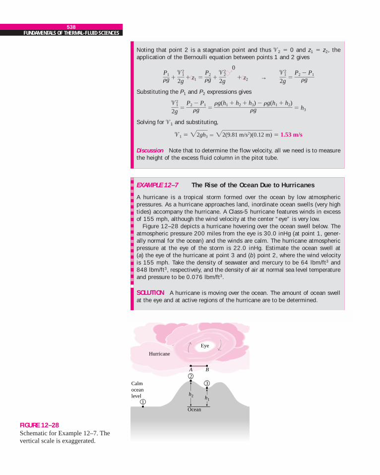
EXAMPLE 12–7 The Rise of the Ocean Due to Hurricanes
A hurricane is a tropical storm formed over the ocean by low atmosphericpressures. As a hurricane approaches land, inordinate ocean swells (very hightides) accompany the hurricane. A Class-5 hurricane features winds in excessof 155 mph, although the wind velocity at the center “eye” is very low.
Figure 12–28 depicts a hurricane hovering over the ocean swell below. Theatmospheric pressure 200 miles from the eye is 30.0 inHg (at point 1, gener-ally normal for the ocean) and the winds are calm. The hurricane atmosphericpressure at the eye of the storm is 22.0 inHg. Estimate the ocean swell at(a) the eye of the hurricane at point 3 and (b) point 2, where the wind velocityis 155 mph. Take the density of seawater and mercury to be 64 lbm/ft3 and848 lbm/ft3, respectively, and the density of air at normal sea level temperatureand pressure to be 0.076 lbm/ft3.
SOLUTION A hurricane is moving over the ocean. The amount of ocean swellat the eye and at active regions of the hurricane are to be determined.
→
FIGURE 12–28Schematic for Example 12–7. Thevertical scale is exaggerated.
Calmoceanlevel
Ocean
Hurricane
Eye
1
23
h1h2
A B
CHAPTER 12539
Assumptions 1 The airflow within the hurricane is steady, incompressible, andirrotational (so that the Bernoulli equation is applicable). (This is certainly avery questionable assumption for a highly turbulent flow, but it is justified inthe solution.) 2 The effect of water drifted into the air is negligible.Properties The densities of air at normal conditions, seawater, and mercury aregiven to be 0.076 lbm/ft3, 64 lbm/ft3, and 848 lbm/ft3, respectively.Analysis (a) Reduced atmospheric pressure over the water causes the water torise. Thus, decreased pressure at point 2 relative to point 1 causes the oceanwater to rise at point 2. The same is true at point 3, where the storm air veloc-ity is negligible. The pressure difference given in terms of the mercury columnheight can be expressed in terms of the seawater column height by
�P � (rgh)Hg � (rgh)sw → hsw � hHg
Then the pressure difference between points 1 and 2 in terms of the seawatercolumn height becomes
h1 � � [(30 � 22) inHg] � 8.83 ft
which is equivalent to the storm surge at the eye of the hurricane since the windvelocity there is negligible and there are no dynamic effects.
(b) To determine the additional rise of ocean water at point 2 due to the highwinds at that point, we write the Bernoulli equation between points A and B,which are on top of the points 2 and 3, respectively. Noting that �B � 0 (the eyeregion of the hurricane is relatively calm) and zA � zB (both points are on thesame horizontal line), the Bernoulli equation simplifies to
� zA � � zB →
Substituting,
� 803 ft
where r is the density of air in the hurricane. Noting that the density of an idealgas at constant temperature is proportional to absolute pressure and the densityof air at the normal atmospheric pressure of 14.7 psia � 30 inHg is 0.076lbm/ft3, the density of air in the hurricane is
rair � ratm air � (0.076 lbm/ft3) � 0.056 lbm/ft3
Using the relation developed above in part (a), the seawater column heightequivalent to 803 ft of air column height is determined to be
hdynamic � � (803 ft) � 0.70 ft
Therefore, the pressure at point 2 is 0.70 ft seawater column lower than thepressure at point 3 due to the high wind velocities, causing the ocean to rise anadditional 0.70 ft. Then the total storm surge at point 2 becomes
h2 � h1 � hdynamic � 8.83 � 0.70 � 9.53 ft
a0.056 lbm/ft3
64 lbm/ft3 brairrsw
hair
a22 inHg30 inHg
bPair
Patm air
PB � PA
rg ��2
A
2g�
(155 mph)2
2(32.2 ft/s2) a1.4667 ft/s
1 mphb2
PB � PA
rg ��2
A
2gPB
rg ��2
B
2g
0PA
rg ��2
A
2g
a 1 ft12 in
ba848 lbm/ft3
64 lbm/ft3 brHg
rsw hHg
rHg
rsw
→
540FUNDAMENTALS OF THERMAL-FLUID SCIENCES
EXAMPLE 12–8 Bernoulli Equation for Compressible Flow
Derive the Bernoulli equation when the compressibility effects are not negligi-ble for an ideal gas undergoing (a) an isothermal process and (b) an isentropicprocess.
SOLUTION The Bernoulli equation for compressible flow is to be obtained foran ideal gas for isothermal and isentropic processes.Assumptions 1 The flow is steady, and frictional effects are negligible. 2 Thefluid is an ideal gas, so the relation P � rRT is applicable. 3 The specific heatsare constant so that P/rk � constant during an isentropic process.Analysis (a) When the compressibility effects are significant and the flowcannot be assumed to be incompressible, the Bernoulli equation is given byEq. 12–17 as
� gz � constant (1)
The compressibility effects can be properly accounted for by expressing r interms of pressure, and then performing the integration � dP/r in Eq. (1). Butthis requires a relation between P and r for the process. For the isothermal ex-pansion or compression of an ideal gas, the integral in Eq. (1) can be performedeasily by noting that T � constant and substituting r � P/RT. It gives
� RT ln P
Substituting into Eq. (1) gives the desired relation,
Isothermal process: RT ln P � � gz � constant (2)
(b) A more practical case of compressible flow is the isentropic flow of idealgases through equipment that involves high-speed fluid flow such as nozzles,diffusers, and the passages between turbine blades. Isentropic (i.e., reversibleand adiabatic) flow is closely approximated by these devices, and it is char-acterized by the relation P/rk � C � constant where k is the specific heat ra-tio of the gas. Solving for r from P/rk � C gives r � C �1/k P 1/k. Performing theintegration,
C 1/k P �1/k dP � C 1/k (3)P�1/k�1
�1/k � 1�
P 1/k
r P�1/k�1
�1/k � 1� a k
k � 1b Pr�dP
r � �
�2
2
�dPr � � dP
P/RT
� dPr �
�2
2
Discussion This problem involves highly turbulent flow and the intense break-down of the streamlines, and thus the applicability of the Bernoulli equation inpart (b) is questionable. The Bernoulli analysis can be thought of as the limit-ing, ideal case, and shows that the rise of seawater due to high-velocity windscannot be more than 0.70 ft.
The wind power of hurricanes is not the only cause of damage to coastalareas. Ocean flooding and erosion from excessive tides is just as serious, as arehigh waves generated by the storm turbulence and energy.
12–4 ENERGY ANALYSIS OF STEADY-FLOWSYSTEMS
For steady-flow systems, the time rate of change of the energy content of thecontrol volume is zero. When the work associated with electric, magnetic, sur-face tension, and viscous effects are negligible, the steady-flow energy equa-tion can be expressed as (see Chap. 5)
(12–26)
It states that the net rate of energy transfer to a control volume by heat andwork transfers during steady flow is equal to the difference between the ratesof outgoing and incoming energy flows with mass.
Many practical problems involve just one inlet and one outlet (Fig. 12–29).The mass flow rate for such single-stream systems remains constant, and Eq.12–26 reduces to
(12–27)�
Qnet in ��
Wshaft, net in � �m ah2 � h1 ��2
2 � �21
2� g(z2 � z1)b
�Qnet in �
�Wshaft, net in � �
out
�m ah ��2
2� gzb� �
in
�m ah ��2
2� gzb
■
CHAPTER 12541
Substituting, the Bernoulli equation for steady, isentropic, compressible flow ofan ideal gas becomes
Isentropic flow: � gz � constant (4a)
or
� gz2 (4b)
A common practical situation involves the acceleration of a gas from rest (stag-nation conditions at state 1) with negligible change in elevation. In that casewe have z1 � z2, �1 � 0. Noting that r � P/RT for ideal gases, P/rk � constantfor isentropic flow, and the Mach number is defined as Ma � �/c wherec � is the local speed of sound for ideal gases, the relation above sim-plifies to
(4c)
where state 1 is the stagnation state and state 2 is any state along the flow.
Discussion It can be shown that the results obtained using the compressibleand incompressible equations deviate no more than 2 percent when the Machnumber is less than 0.3. Therefore, the flow of an ideal gas can be consideredto be incompressible when Ma � 0.3. For atmospheric air at normal conditions,this corresponds to a flow speed of about 100 m/s or 360 km/h, which coversour range of interest.
P1
P2� c1 � ak � 1
2b Ma 2
2 dk /(k�1)
2kRT
a kk � 1
b P1r1
��2
1
2� gz1 � a k
k � 1b P2r2
��2
2
2
a kk � 1
b Pr��2
2
+ + h1
Qnet in + Wshaft, net in
gz121m⋅
⋅ ⋅
2�
In
Out
Fixedcontrolvolume
2
1
+ + h2 gz222m⋅2�
FIGURE 12–29 A control volume with only one inlet
and one outlet and energy interactions.
where subscripts 1 and 2 stand for inlet and outlet, respectively. The steady-flow energy equation on a unit mass basis is obtained by dividing Eq. 12–27by the mass flow rate ,
(12–28)
where is the net heat transfer to the fluid per unit mass and is the work input to the fluid per unit mass. Using
the definition of enthalpy and rearranging, the steady-flow en-ergy equation can also be expressed as
(12–29)
where u is the internal energy, P/r is the flow energy, is the kinetic en-ergy, and gz is the potential energy of the fluid per unit mass. These relationsare valid for both compressible or incompressible flows.
The left side of Eq. 12–29 represents the mechanical energy input while thefirst three terms on the right side represent the mechanical energy output. Ifthe flow is ideal with no irreversibilities such as friction, the total mechanicalenergy must be conserved, and the terms in parentheses must equal zero. That is,
Ideal flow (no mechanical energy loss) (12–30)
Any increase in above is due to the irreversible conversion ofmechanical energy to thermal energy, and thus represents themechanical energy loss (Fig. 12–30). That is,
Mechanical energy loss: (12–31)
For single-phase fluids (a gas or a liquid), we have u2 � u1 � Cυ(T2 � T1)where Cυ is the constant-volume specific heat. Then the steady-flow energyequation on a unit mass basis can be written conveniently as a mechanicalenergy balance as
(12–32)
or
(12–33)
Noting that , the mechanicalenergy balance can be written more explicitly as
(12–34)
where wpump is the mechanical work input (due to the presence of a pump, fan,compressor, etc.) and wturbine is the mechanical work output. When the flow isincompressible, either absolute or gage pressure can be used for P since Patm/rwould appear on both sides, and would cancel out.
P1r1
��2
1
2� gz1 � wpump �
P2r2
��2
2
2� gz2 � wturbine � emech, loss
wshaft, net in � wshaft, in � wshaft, out � wpump � wturbine
wshaft, net in �P1r1
��2
1
2� gz1 �
P2r2
��2
2
2� gz2 � emech, loss
emech, in � emech, out � emech, loss
emech, loss � u2 � u1 � qnet in
u2 � u1 � qnet in
qnet inu2 � u1
qnet in � u2 � u1
(u2 � u1 � qnet in)
�2/2
wshaft, net in �P1r1
��2
1
2� gz1 �
P2r2
� gz2 � (u2 � u1 � qnet in)
h � u � P/rwshaft, net in �
�Wshaft, net in / �m
qnet in ��
Qnet in/ �m
qnet in � wshaft, net in � h2 � h1 ��2
2 � �21
2� g(z2 � z1)
�m
542FUNDAMENTALS OF THERMAL-FLUID SCIENCES
15.2°C
15.0°C
Water
0.7 kg/s
∆u = 0.84 kJ/kg∆T = 0.2°C
2 kW pump = 0.70η
FIGURE 12–30The lost mechanical energy in a fluidflow system results in an increase inthe internal energy of the fluid, andthus in a rise of fluid temperature.
Multiplying Eq. 12–34 by the mass flow rate gives
(12–35)
where is the shaft power input through the pump’s shaft, is theshaft power output through the turbine’s shaft, and mech, loss is the total me-chanical power loss, which consists of pump and turbine losses as well as thefrictional losses in the piping network. That is, mech, loss � mech, loss, pump �
mech, loss, turbine � mech, loss, piping. The energy equation can also be expressed interms to heads as
(12–36)
where
The pump head is zero if the piping system does not involve a pump, a fan, ora compressor, the turbine head is zero if the system does not involve a turbine,and both are zero if the flow section analyzed does not involve any mechani-cal work producing or consuming devices. Also, the head loss is zero in anidealized situation that does not involve any frictional losses.
Special Case: Incompressible Flow with NoMechanical Work Devices and Negligible FrictionWhen the frictional effects are negligible, there is no dissipation of mechani-cal energy into thermal energy, and thus hL � emech, loss, piping/g � 0, as shownin Example 12–9. Also, hpump, u � hturbine, e � 0 when there are no mechanicalwork devices such as fans, pumps, or turbines, and r1 � r2 � r when the fluidis incompressible. Then equation 12–36 reduces to (Fig. 12–31)
(12–37)
which is the Bernoulli equation derived earlier using Newton’s second law ofmotion.
P1rg �
�21
2g� z1 �
P2rg �
�22
2g� z2 or P
rg ��2
2g� z � constant
hL �emech, loss, piping
g �
�Emech, loss, piping
�mg is the irreversible head loss between 1 and 2.
hturbine, e �wturbine, e
g �
�Wturbine, e
�mg is the extracted head from the fluid by the turbine,
hpump, u �wpump, u
g �
�Wpump, u
�mg is the useful head delivered to the fluid by the pump,
P1r1g �
�21
2g� z1 � hpump, u �
P2r2g �
�22
2g� z2 � hturbine, e � hL
�E
�E
�E
�E
�E
�Wturbine
�Wpump
�m aP1r1
��2
1
2� gz1b�
�Wpump � �m aP2
r2�
�22
2� gz2b�
�Wturbine �
�Emech, loss
�m
CHAPTER 12543
FIGURE 12–31When the frictional losses are
negligible and there are no workdevices involved, the energy equation
for steady incompressible flowreduces to the Bernoulli equation.
Energy equation:
–– + + z1 + hpump, u = P1gρ ρ ––�1
2
2g–– + + z2 + hturbine, e + hLP2g ––�2
2
2g
Bernoulli equation:
0
–– + + z1 =P1gρ ρ ––�1
2
2g–– + + z2P2g ––�2
2
2g
0 0
Kinetic Energy Correction Factor, aThe mean flow velocity �m was defined such that the relation r�mA gives theactual mass flow rate. Therefore, there is no such thing as a correction factorfor mass flow rate. However, the kinetic energy of a fluid stream obtainedfrom �2/2 is not the same as the actual kinetic energy of the fluid stream sincethe square of a sum is not equal to the sum of the squares of its components(Fig. 12–32). This error can be corrected by replacing the kinetic energy terms�2/2 in the energy equation by a�m
2 /2 where a is the kinetic energy correc-tion factor. By using equations for the variation of velocity with the radialdistance, it can be shown that the correction factor is 2.0 for fully developedlaminar pipe flow, and it ranges between 1.04 and 1.11 for turbulent flow in acircular pipe.
The kinetic energy correction factors are usually disregarded in an elemen-tary analysis since (1) most flows encountered in practice are turbulent, forwhich the correction factor is near unity, and (2) the kinetic energy terms areusually small relative to the other terms in the energy equation, and multiply-ing them by a factor less than 2.0 does not make much difference. Besides,when the velocity and thus the kinetic energy are high, the flow turns turbu-lent. Therefore, we will not consider the kinetic energy correction factor in theanalysis. However, the reader should keep in mind that he or she may en-counter situations for which these factors are significant, especially when theflow is laminar.
544FUNDAMENTALS OF THERMAL-FLUID SCIENCES
FIGURE 12–32The determination of the kineticenergy correction factor using actualvelocity distribution �(r) and themean velocity �m at a cross section.
KEact = ∫keδm = ∫A
∫A
�2 (r)[ �(r) dA]ρ· ·
·
m = �m A, = constantρρ
�(r) A
·
––12
A�3mρ––1
2KEm = =m�2
m·
––12
KEact =α =3
dA( )·
KEm· ––––––––
�(r)�m
–––1A
∫A�3(r) dAρ= ––12
EXAMPLE 12–9 Effect of Friction on Fluid Temperature andHead Loss
Show that during steady and incompressible flow of a fluid in an adiabatic flowsection (a) the temperature remains constant and there is no head loss whenthe flow is frictionless and (b) the temperature increases and some head lossoccurs when there are frictional effects. Discuss if it is possible for the fluidtemperature to decrease during such flow (Fig. 12–33).
SOLUTION Steady and incompressible flow through an adiabatic section isconsidered. The effects of friction on the temperature and the heat loss are tobe determined.Assumptions 1 The flow is steady and incompressible. 2 The flow section isadiabatic and thus there is no heat transfer.Analysis The density of a fluid remains constant during incompressible flow,and the entropy change of an incompressible system is
�s � Cυ ln
This relation represents the entropy change of the fluid per unit mass as it flowsthrough the flow section from state 1 at the inlet to state 2 at the exit. Entropychange is caused by two effects: (1) heat transfer and (2) irreversibilities.Therefore, in the absence of heat transfer, entropy change is due to irreversibil-ities only whose effect is always to increase entropy.
(a) The entropy change of the fluid is zero when the process does not involveany irreversibilities such as friction and swirling, and thus for reversible flowwe have
T2
T1
FIGURE 12–33Schematic for Example 12–9.
1 2
T1u1
T2u2
= constantρ
(adiabatic)
CHAPTER 12545
Temperature change: �s � Cυ ln � 0 → T2 � T1
Mechanical energy loss: emech, loss � u2 � u1 � Cυ(T2 � T1) � 0
Head loss: hL � emech, loss /g � 0
Thus we conclude that when heat transfer and frictional effects are negligible,(1) the temperature of the fluid remains constant, (2) no mechanical energy isconverted to thermal energy, and (3) there is no head loss.(b) When there are irreversibilities such as friction, the entropy change is posi-tive and thus we have:
Temperature change: �s � Cυ ln � 0 → T2 � T1
Mechanical energy loss: emech, loss � u2 � u1 � Cυ (T2 � T1) � 0
Head loss: hL � emech, loss /g � 0
Thus we conclude that when the flow is adiabatic and irreversible, (1) the tem-perature of the fluid increases, (2) some mechanical energy is converted tothermal energy, and (3) some head loss occurs.Discussion It is impossible for the fluid temperature to decrease duringsteady, incompressible, adiabatic flow since this would require the entropy of anadiabatic system to decrease, which would be a violation of the second law ofthermodynamics.
T2
T1
T2
T1
EXAMPLE 12–10 Pumping Power and Frictional Heating in aPump
The pump of a water distribution system is powered by a 15-kW electric motorwhose efficiency is 90 percent (Fig. 12–34). The water flow rate through thepump is 50 L/s. The diameters of the inlet and exit pipes are the same, and theelevation difference across the pump is negligible. If the pressures at the inletand outlet of the pump are measured to be 100 kPa and 300 kPa (absolute),respectively, determine (a) the mechanical efficiency of the pump and (b) thetemperature rise of water as it flows through the pump due to the mechanicalinefficiency.
SOLUTION The pressures across a pump are measured. The mechanical effi-ciency of the pump and the temperature rise of water are to be determined.Assumptions 1 The flow is steady and incompressible. 2 The pump is driven byan external motor so that the heat generated by the motor is dissipated to theatmosphere. 3 The elevation difference between the inlet and outlet of thepump is negligible, z1 � z2. 4 The inlet and outlet diameters are the same andthus the inlet and exit velocities are equal, �1 � �2.Properties We take the density of water to be 1 kg/L � 1000 kg/m3 and itsspecific heat to be 4.18 kJ/kg · �C.Analysis (a) The mass flow rate of water through the pump is
� � (1 kg/L)(50 L/s) � 50 kg/s
The motor draws 15 kW of power and is 90 percent efficient. Thus the me-chanical (shaft) power it delivers to the pump is
�Wpump, shaft � hmotor
�Welectric � (0.90)(15 kW) � 13.5kW
r�V�m
FIGURE 12–34Schematic for Example 12–10.
300 kPa
Water
Motor15 kW
motor = 90%η
50 L/s
100 kPa1
2
Wpump·
546FUNDAMENTALS OF THERMAL-FLUID SCIENCES
To determine the mechanical efficiency of the pump, we need to know theincrease in the mechanical energy of the fluid as it flows through the pump,which is
� mech, fluid � mech, out � mech, in � �
Simplifying it for this case and substituting the given values,
� mech, fluid � � (50 kg/s) � 10 kW
Then the mechanical efficiency of the pump becomes
� 0.741 or 74.1%
(b) Of the 13.5-kW mechanical power supplied by the pump, only 10 kW is im-parted to the fluid as mechanical energy. The remaining 3.5 kW is converted tothermal energy due to frictional effects, and this “lost” mechanical energy man-ifests itself as a heating effect in the fluid,
The temperature rise of water due to this mechanical inefficiency is determinedfrom the thermal energy balance, mech, loss � (u2 � u1) � C�T. Solving for �T,
� 0.017�C
Therefore, the water will experience a temperature rise of 0.017�C, which isvery small, as it flows through the pump.Discussion In an actual application, the temperature rise of water will proba-bly be less since part of the heat generated will be transferred to the casing ofthe pump, and from the casing to the surrounding air. If the entire pump motorwere submerged in water, then the 1.5 kW dissipated to the air due to motor in-efficiency would also be transferred to the surrounding water as heat. Thiswould cause the water temperature to rise more.
�T �
�Emech, loss
�mC�
3.5 kW(50 kg/s)(4.18 kJ/kg � �C)
�m�m�E
�E
�W
�E
hpump ��
�Emech, fluid�
Wpump, shaft
�10 kW13.5kW
a(300 � 100) kPa
1000 kg/m3 ba 1 kJ1 kPa � m3b�m aP2 � P1
r b�E
�m aP1r �
�21
2� gz1b�m aP2
r ��2
2
2� gz2b�
E�E
�E
EXAMPLE 12–11 Hydroelectric Power Generation from a Dam
In a hydroelectric power plant, 100 m3/s of water flows from an elevation of120 m to a turbine, where electric power is generated (Fig. 12–35). The totalhead loss in the system from point 1 to point 2 (excluding the turbine unit) isdetermined to be 35 m. If the overall efficiency of the turbine-generator is 80percent, estimate the electrical power output.
SOLUTION The available head, flow rate, head loss, and efficiency of a hydro-electric turbine are given. The electrical power output is to be determined.Assumptions 1 The flow is steady and incompressible. 2 The water levels at thereservoir and the discharge site remain constant.FIGURE 12–35
Schematic for Example 12–11.
turbine-gen = 80%η
100 m3/s
hL = 35m
2
120 m
1
Generator
Turbine
CHAPTER 12547
Properties We take the density of water to be 1000 kg/m3.Analysis The mass flow rate of water through the turbine is
� r � (1000 kg/m3)(100 m3/s) � 105 kg/s
We take point 2 as the reference level, and thus z2 � 0. Also, both points 1 and2 are open to the atmosphere (P1 � P2 � Patm) and the flow velocities are neg-ligible at both points (�1 � �2 � 0). Then the energy equation for steady in-compressible flow reduces to
Substituting, the extracted turbine head and the corresponding turbine powerare determined to be
hturbine, e � z1 � hL � 120 � 35 � 85 m
turbine, e � ghturbine, e � (105 kg/s)(9.81 m/s2)(85 m) � 83,400 kW
Therefore, a perfect turbine-generator would generate 83,400 kW of electricityfrom this resource. The electric power generated by the actual unit is
electric � hturbine-gen turbine, e � (0.80)(83.4 MW) � 66.7 MW
Discussion Note that the power generation will increase by almost 1 MW foreach percentage point improvement in the efficiency of the turbine-generatorunit.
�W
�W
a 1 kJ/kg
1000 m2/s2b�m�
W
�V�m
→ →
EXAMPLE 12–12 Fan Selection for Air Cooling of a Computer
A fan is to be selected to cool a computer case whose dimensions are 12 cm 40 cm 40 cm (Fig. 12–36). Half of the volume in the case is expected to befilled with components and the other half to be air space. A 6-cm-diameter holeis available at the front of the case for the installation of the fan that is to re-place the air in the void spaces of the case once every second. Small low-powerfan-motor-combined units are available in the market and their efficiency is es-timated to be 30 percent. Determine (a) the wattage of the fan-motor unit to bepurchased and (b) the pressure difference across the fan. Take the air densityto be 1.20 kg/m3.
SOLUTION A fan is to cool a computer case by completely replacing the air in-side once every second. The power of the fan and the pressure difference acrossit are to be determined.Assumptions 1 The flow is steady and incompressible. 2 Losses other thanthose due to the inefficiency of the fan-motor unit are negligible (hL � 0).Properties The density of air is given to be 1.20 kg/m3.Analysis (a) Noting that half of the volume of the case is occupied by thecomponents, the air volume in the computer case is
V � (Void fraction)(Total case volume)
� 0.5(12 cm 40 cm 40 cm) � 9600 cm3
FIGURE 12–36Schematic for Example 12–12.
Fan
Streamline
�21 2
3 4 Welect·
� z1 � hpump, u0
� � z20
� hturbine, e � hL → hturbine, e � z1 � hL
P1rg �
�22
2gP1rg �
�21
2g
548FUNDAMENTALS OF THERMAL-FLUID SCIENCES
Therefore, the volume and mass flow rates of air through the case are
� � � 9600 cm3/s � 9.6 10�3 m3/s
� r � (1.20 kg/m3)(9.6 10�3 m3/s) � 0.0115 kg/s
The cross-sectional area of the opening in the case and the average air ve-locity are
A � � � 2.83 10�3 m2
� � � � 3.39 m/s
We draw the control volume around the fan such that both the inlet and the exitare at the atmospheric pressure (P1 � P2 � Patm), as shown in the figure, andthe inlet section 1 is large and far from the fan so that the flow velocity at theinlet section is negligible (�1 � 0). Noting that z1 � z2 and the mechanicallosses due to fan inefficiency and the frictional effects in flow are disregarded,the energy equation simplifies to
� fan� � turbine0
� mech, loss0
Solving for fan and substituting,
fan � � (0.0115 kg/s) � 0.066 W
Then the required electrical power input to the fan is determined to be
elect � � 0.22 W
Therefore, a fan-motor rated at 0.22 W is adequate for this job.
(b) To determine the pressure difference across the fan unit, we take points3 and 4 to be on the two sides of the fan on a horizontal line. This time againz3 � z4 and �3 � �4 since the fan is a narrow cross section. Disregarding me-chanical losses, the energy equation reduces to
� fan � � mech, loss0
→ fan �
Solving for P4 � P3 and substituting,
P4 � P3 � � 6.9 Pa
Therefore, the pressure rise across the fan is 6.9 Pa.Discussion The efficiency of the fan-motor unit is given to be 30 percent,which means 30 percent of the electric power W· electric consumed by the unit willbe converted to useful mechanical energy while the rest (70 percent) will be“lost” and converted to thermal energy. Also, a much larger fan is required in anactual system to overcome frictional losses inside the computer case.
r�
Wfan
�m�
(1.2 kg/m3)(0.066 W)0.0115 kg/s
a1 Pa � m3
1 Wsb
�m P4 � P3r
�W
�E�m
P4r
�W�m
P3r
�Wfanhfan-motor
�0.066 W
0.3�
W
(3.39 m/s)2
2 a 1 N
1 kg � m/s2b�m �2
2
2�
W
�W
�E
�W�m aP2
r ��2
2
2� gz2
0b�W�m aP1
r ��2
1
2
0
� gz1 0b
9.6 10�3 m3/s2.83 10�3 m2
�VA
p(0.06 m)2
14pD 2
4
�V�m
9600 cm3
1 sV�t
�V
→ →
→ → →
→
CHAPTER 12549
EXAMPLE 12–13 Head and Power Loss during Water Pumping
Water is pumped from a lower reservoir to a higher reservoir by a pump that pro-vides 20 kW of useful mechanical power to water (Fig. 12–37). The free surfaceof the upper reservoir is 45 m higher than the surface of the lower reservoir. Ifthe flow rate of water is measured to be 0.03 m3/s, determine the head loss ofthe system and the lost mechanical power during this process.
SOLUTION Water is pumped from a lower reservoir to a higher one. The headand power loss associated with this process are to be determined.Assumptions 1 The flow is steady and incompressible. 2 The elevation differ-ence between the reservoirs is constant.Properties We take the density of water to be 1000 kg/m3.Analysis The mass flow rate of water through the system is
� r � (1000 kg/m3)(0.03 m3/s) � 30 kg/s
We choose points 1 and 2 at the free surfaces of the lower and upper reservoirs,respectively, and take the surface of the lower reservoir as the reference level(z1 � 0). Both points are open to the atmosphere (P1 � P2 � Patm) and the ve-locities at both locations are negligible (�1 � �2 � 0). Then the energy equa-tion for steady incompressible flow for a control volume between 1 and 2reduces to
� pump� � turbine0
� mech, loss
pump � gz2 � mech, loss → mech, loss � pump � gz2
Substituting, the lost mechanical power and head loss are determined to be
mech, loss � 20 kW � (30 kg/s)(9.81 m/s2)(45 m)
� 6.76 kW
hL � � 23.0 m
since the entire mechanical losses are due to frictional losses in the pipes.
Discussion The 6.76 kW of power is used to overcome the friction in the pip-ing system. Note that the pump could raise the water an additional 23 m ifthere were no losses in the system. In this ideal case, the pump would functionas a turbine when the water is allowed to flow from the upper reservoir to thelower reservoir, and generate 20 kW of power.
�Emech, loss
�mg�
6.76 kW(30 kg/s)(9.81 m/s2)
a1 kg � m/s2
1 Nba1000 N � m/s
1 kWb
a 1 N1 kg � m/s2ba 1 kW
1000 N � m/sb�
E
�m�
W�
E�
E�m�
W
�E
�W�m aP2
r ��2
2
2
0� gz2b�
W�m aP1r �
�21
2
0
� gz1 0b
�V�m FIGURE 12–37
Schematic for Example 12–13.
0.03 m3/s
z1 = 01
45 m
2
Pump
Systemboundary
20 kW
→ →
→ →
SUMMARY
This chapter deals with the Bernoulli and the energy equations,and their applications. The mechanical energy is the form ofenergy associated with the velocity, elevation, and pressure of
the fluid, and it can be converted to mechanical work com-pletely and directly by an ideal mechanical device. The effi-ciencies of various devices are defined as
550FUNDAMENTALS OF THERMAL-FLUID SCIENCES
The Bernoulli equation is a relation between pressure, velocity,and elevation in steady incompressible flow, and is expressedalong a streamline and in regions where net viscous forces arenegligible as
It can also be expressed between any two points on the stream-line as
The Bernoulli equation is an expression of mechanical energybalance and can be stated as the sum of the kinetic, potential,and flow energies of a fluid particle is constant along a stream-line during steady flow when the compressibility and frictionaleffects are negligible. Multiplying the Bernoulli equation bydensity gives
P � r � rgz � constant
where P is the static pressure, which represents the actual pres-sure of the fluid; r�2/2 is the dynamic pressure, which repre-
sents the pressure rise when the fluid in motion is brought to astop; and rgz is the hydrostatic pressure, which accounts forthe effects of fluid weight on pressure. The sum of the static,dynamic, and hydrostatic pressures is called the total pressure.The Bernoulli equation states that the total pressure along astreamline is constant. The sum of the static and dynamic pres-sures is called the stagnation pressure, which represents thepressure at a point where the fluid is brought to a complete stopin a frictionless manner. The Bernoulli equation can also berepresented in terms of “heads” by dividing each term by g,
where P/rg is the pressure head, which represents the height ofa fluid column that produces the static pressure P; �2/2g is thevelocity head, which represents the elevation needed for a fluidto reach the velocity � during frictionless free fall; and z is theelevation head, which represents the potential energy of thefluid. Also, H is the total head for the flow. The line that repre-sents the sum of the static pressure and the elevation heads,P/rg � z, is called the hydraulic grade line (HGL), and the linethat represents the total head of the fluid, P/rg � �2/2g � z, iscalled the energy grade line (EGL).
The energy equation for steady incompressible flow can beexpressed as
� gz1 � wpump � � gz2
� wturbine � emech, loss
� pump �
� turbine � mech, loss
� z1 � hpump, u � � z2 � hturbine, e � hL
where
emech, loss � u2 � u1 � qnet in
hL �emech loss, piping
g �
�Emech loss, piping
�mg
hturbine, e �wturbine, e
g �
�Wturbine, e
�mg
hpump, u �wpump, u
g �
�Wpump, u
�mg
P2rg �
�22
2gP1rg �
�21
2g
�E
�W
�m aP2r �
�22
2� gz2b�
W�m aP1r �
�21
2� gz1b
P2r �
�22
2P1r �
�21
2
Prg �
�2
2g� z � H � constant
�2
2
P1r �
�21
2� gz1 �
P2r �
�22
2� gz2
Pr�
�2
2� gz � constant
�
�Welect, out
�Emech, in �
�Emech, out
�
�Welect, out
�� �Emech, fluid�
hturbine-gen � hturbine hgenerator
��
�Emech, fluid�
Welect, in
hpump-motor � hpump hmotor �
�Emech, out �
�Emech, in
�Welect, in
hgenerator �Electrical power outputMechanical power input
�
�Welect, out�
Wshaft, in
hmotor �Mechanical power output
Electrical power input�
�Wshaft, out
�Welect, in
�
�Wshaft, out
�� �Emech, fluid�
��
Wturbine�
Wturbine, e
hturbine �Mechanical energy output
Mechanical energy decrease of the fluid
��
�Emech, fluid�
Wshaft, in
��
Wpump, u�
Wpump
hpump �Mechanical energy increase of the fluid
Mechanical energy input
CHAPTER 12551
REFERENCES AND SUGGESTED READING
1. C. T. Crowe, J. A. Roberson, and D. F. Elger. EngineeringFluid Mechanics. 7th ed. New York: Wiley, 2001.
2. R. C. Dorf, ed. in chief. The Engineering Handbook. BocaRaton, FL: CRC Press, 1995.
3. B. R. Munson, D. F. Young, and T. Okiishi. Fundamentalsof Fluid Mechanics. 4th ed. New York: Wiley, 2002
4. Panton, R. L. Incompressible Flow. 2nd ed. New York:Wiley, 1996.
5. M. C. Potter and D. C. Wiggert. Mechanics of Fluids.2nd ed. Upper Saddle River, NJ: Prentice Hall, 1997.
6. M. Van Dyke. An Album of Fluid Motion. Stanford, CA:The Parabolic Press, 1982.
PROBLEMS*
Mechanical Energy and Efficiency
12–1C What is mechanical energy? How does it differ fromthermal energy? What are the forms of mechanical energy of afluid stream?
12–2C What is mechanical efficiency? What does a mechan-ical efficiency of 100 percent mean for a hydraulic turbine?
12–3C How is the combined pump-motor efficiency of apump and motor system defined? Can the combined pump-motor efficiency be greater than either of the pump or themotor efficiency?
12–5 Consider a river flowing toward a lake at an averagevelocity of 3 m/s at a rate of 500 m3/s at a location 90 m abovethe lake surface. Determine the total mechanical energy of theriver water per unit mass and the power generation potential ofthe entire river at that location. Answer: 444 MW
FIGURE P12–5
12–6 Electrical power is to be generated by installing a hy-draulic turbine-generator at a site 70 m below the free surfaceof a large water reservoir that can supply water at a rate of1500 kg/s steadily. If the mechanical power output of the tur-bine is 800 kW and the electrical power generation is 750 kW,determine the turbine efficiency and the combined turbine-generator efficiency of this plant. Neglect losses in the pipes.
12–7 At a certain location, wind is blowing steadily at 12 m/s.Determine the mechanical energy of air per unit mass and thepower generation potential of a wind turbine with 50-m-diameter blades at that location. Also determine the actual elec-tric power generation assuming an overall efficiency of 30percent. Take the air density to be 1.25 kg/m3.
12–8 Reconsider Prob. 12–7. Using EES (or other)software, investigate the effect of wind velocity
and the blade span diameter on wind power generation. Let thevelocity vary from 5 m/s to 20 m/s in increments of 5 m/s, andthe diameter to vary from 20 m to 80 m in increments of 20 m.Tabulate the results, and discuss their significance.
12–9E A differential thermocouple with sensors at the inletand exit of a pump indicates that the temperature of water rises0.072°F as it flows through the pump at a rate of 1.5 ft3/s. If theshaft power input to the pump is 27 hp, determine the mechan-ical efficiency of the pump. Answer: 64.7%
FIGURE P12–9E
12–10 Water is pumped from a lake to a storage tank 20 mabove at a rate of 70 L/s while consuming 20.4 kW of electricpower. Disregarding any frictional losses in the pipes and anychanges in kinetic energy, determine (a) the overall efficiencyof the pump-motor unit and (b) the pressure difference betweenthe inlet and the exit of the pump.
∆T = 0.072° F
Pump
River 3 m/s
90 m
*Problems designated by a “C” are concept questions, andstudents are encouraged to answer them all. Problems designatedby an “E” are in English units, and the SI users can ignore them.Problems with a CD-EES icon are solved using EES, andcomplete solutions together with parametric studies are includedon the enclosed CD. Problems with a computer-EES icon arecomprehensive in nature, and are intended to be solved with acomputer, preferably using the EES software that accompaniesthis text.
552FUNDAMENTALS OF THERMAL-FLUID SCIENCES
FIGURE P12–10
Bernoulli Equation
12–11C What is streamwise acceleration? How does it differfrom normal acceleration? Can a fluid particle accelerate insteady flow?
12–12C Express the Bernoulli equation in three differentways using (a) energies, (b) pressures, and (c) heads.
12–13C What are the three major assumptions used in thederivation of the Bernoulli equation?
12–14C Define static, dynamic, and hydrostatic pressure.Under what conditions is their sum constant for a flow stream?
12–15C What is stagnation pressure? Explain how it can bemeasured.
12–16C Define pressure head, velocity head, and elevationhead for a fluid stream and express them for a fluid streamwhose pressure is P, velocity is �, and elevation is z.
12–17C What is the hydraulic grade line? How does it differfrom the energy grade line? Under what conditions do bothlines coincide with the free surface of a liquid?
12–18C How is the location of the hydraulic grade line de-termined for open-channel flow? How is it determined at theexit of a pipe discharging to the atmosphere?
12–19C The water level of a tank on a building roof is 20 mabove the ground. A hose leads from the tank bottom to theground. The end of the hose has a nozzle, which is pointedstraight up. What is the maximum height to which the watercould rise? What factors would reduce this height?
12–20C In a certain application, a siphon must go over ahigh wall. Can water or oil with a specific gravity of 0.8 goover a higher wall? Why?
12–21C Explain how and why a siphon works. Someoneproposes siphoning cold water over a 7-m-high wall. Is thisfeasible? Explain.
12–22C A student siphons water over a 8.5-m wall at sealevel. He then climbs to the summit of Mount Shasta (elevation4390 m, Patm � 58.5 kPa) and attempts the same experiment.Comment on his prospects for success.
12–23C A glass manometer with oil as the working fluid isconnected to an air duct as shown in the figure. Will the oil inthe manometer move as in figure (a) or in figure (b)? Explain.What would your response be if the flow direction is reversed?
FIGURE P12–23C12–24C The velocity of a fluid flowing in a pipe is to bemeasured by two different pitot-type mercury manometersshown in the figure. Would you expect both manometers topredict the same velocity for flowing water? If not, whichwould be more accurate? Explain. What would your responsebe if air were flowing in the pipe instead of water?
FIGURE P12–2412–25 In cold climates, the water pipes may freeze and burstif proper precautions are not taken. In such an occurrence, theexposed part of a pipe on the ground ruptures, and water shootsup to 34 m. Estimate the gage pressure of water in the pipe.State your assumptions and discuss if the actual pressure ismore or less than the value you predicted.
12–26 A pitot tube is used to measure the velocity of an air-craft flying at 3000 m. If the differential pressure reading is3 kPa, determine the velocity of the aircraft.
12–27 While traveling on a dirt road, the bottom of a car hitsa sharp rock and a small hole develops at the bottom of its gastank. If the height of the gasoline in the tank is 30 cm, deter-mine the initial velocity of the gasoline at the hole. Discusshow the velocity will change with time and how the flow willbe affected if the lid of the tank is closed tightly.Answer: 2.43 m/s
12–28E The drinking water needs of an office are metby large water bottles. One end of a 0.25-in-
diameter plastic hose is inserted into the bottle placed on a highstand, while the other end with an on/off valve is maintained2 ft below the bottom of the bottle. If the water level in the bot-tle is 1.5 ft when it is full, determine how long it will take at the
Flow
12
Flow Flow
(a) (b)
Pump
Storage tank
20 m
CHAPTER 12553
minimum to fill an 8-oz glass (� 0.00835 ft3) (a) when the bot-tle is first opened and (b) when the bottle is almost empty.
FIGURE P12–28E
12–29 A piezometer and a pitot tube are tapped into a 3-cm-diameter horizontal water pipe, and the height of the watercolumns are measured to be 20 cm in the piezometer and35 cm in the pitot tube (both measured from the top surface ofthe pipe). Determine the velocity at the center of the pipe.
12–30 The diameter of a cylindrical water tank is Do and itsheight is H. The tank is filled with water, which is open to theatmosphere. An orifice of diameter Do with a smooth entrance(i.e., no losses) is open at the bottom. Develop a relation for thetime required for the tank (a) to empty halfway and (b) toempty completely.
12–31 A pressurized tank of water has a 10-cm-diameter ori-fice at the bottom, where water discharges to the atmosphere.The water level is 3 m above the outlet. The tank air pressureabove the water level is 300 kPa (absolute) while the atmo-spheric pressure is 100 kPa. Neglecting frictional effects, de-termine the initial discharge rate of water from the tank.Answer: 0.168 m3/s
FIGURE P12–31
12–32 Reconsider Prob. 12–31. Using EES (or other)software, investigate the effect of water height in
the tank on the discharge velocity. Let the water height varyfrom 0 to 5 m in increments of 0.5 m. Tabulate and plot theresults.
12–33E A siphon pumps water from a large reservoir to alower tank that is initially empty. The tank also has a roundedorifice 15 ft below the reservoir surface where the water leavesthe tank. Both the siphon and the orifice diameters are 2 in. Ig-noring frictional losses, determine to what height the water willrise in the tank at equilibrium.
12–34 Water enters a tank of diameter DT steadily at a massflow rate of in. An orifice at the bottom with diameter Do al-lows water to escape. The orifice has a rounded entrance, sothe frictional losses are negligible. If the tank is initially empty,(a) determine the maximum height that the water will reach inthe tank and (b) obtain a relation for water height z as a func-tion of time.
FIGURE P12–34
12–35E Water flows through a horizontal pipe at a rate of1 gal/s. The pipe consists of two sections of diameters 4 in and2 in with a smooth reducing section. The pressure differencebetween the two pipe sections is measured by a mercurymanometer. Neglecting frictional effects, determine the differ-ential height of mercury between the two pipe sections.Answer: 0.52 in
FIGURE P12–35E
4 in 2 in
h
Doz
DT
m⋅
�m
3 m
10 cm
Air300 kPa
Water1.5 ft
2 ft
554FUNDAMENTALS OF THERMAL-FLUID SCIENCES
12–36 An airplane is flying at an altitude of 12,000 m. De-termine the gage pressure at the stagnation point on the nose ofthe plane if the speed of the plane is 200 km/h. How would yousolve this problem if the speed were 1050 km/h? Explain.
12–37 The air velocity in the duct of a heating system is to bemeasured by a pitot tube inserted into the duct parallel to flow.If the differential height between the water columns connectedto the two outlets of the pitot tube is 2.4 cm, determine (a) theflow velocity and (b) the pressure rise at the tip of the pitottube. The air temperature and pressure in the duct are 45�C and98 kPa.
12–38 The water in a 10-m-diameter, 2-m-high above-the-ground swimming pool is to be emptied by unplugging a 3-cm-diameter, 25-m-long horizontal pipe attached to the bottom ofthe pool. Determine the maximum discharge rate of waterthrough the pipe. Also, explain why the actual flow rate willbe less.
12–39 Reconsider Prob. 12–38. Determine how long it willtake to empty the swimming pool completely.Answer: 19.7 h
12–40 Reconsider Prob. 12–39. Using EES (or other)software, investigate the effect of the discharge
pipe diameter on the time required to empty the pool com-pletely. Let the diameter vary from 1 to 10 cm in increments of1 cm. Tabulate and plot the results.
12–41 Air at 110 kPa and 50�C flows upward through a6-cm-diameter inclined duct at a rate of 45 L/s. The duct diam-eter is then reduced to 4 cm through a reducer. The pressurechange across the reducer is measured by a water manometer.The elevation difference between the two points on the pipewhere the two arms of the manometer are attached is 0.20 m.Determine the differential height between fluid levels of thetwo arms of the manometer.
FIGURE P12–41
12–42E Air is flowing through a venturi meter whose diam-eter is 2.6 in at the entrance part (location 1) and 1.8 in at thethroat (location 2). The gage pressure is measured to be 12.2psia at the entrance and 11.8 psia at the throat. Neglecting fric-tional effects, show that the volume flow rate can be ex-pressed as
and determine the flow rate of air. Take the air density to be0.075 lbm/ft3.
FIGURE P12–42E
12–43 The water pressure in the mains of a city at a particu-lar location is 400 kPa gage. Determine if this main can servewater to neighborhoods that are 50 m above this location.
12–44 A handheld bicycle pump can be used as an atomizerto generate a fine mist of paint or pesticide by forcing air at ahigh velocity through a small hole and placing a short tube be-tween the liquid reservoir and the high-speed air jet whose lowpressure drives the liquid up through the tube. In such anatomizer, the hole diameter is 0.3 cm, the vertical distance be-tween the liquid level in the tube and the hole is 10 cm, and thebore (diameter) and the stroke of the air pump are 5 cm and20 cm, respectively. If the atmospheric conditions are 20�C and95 kPa, determine the minimum speed that the piston must bemoved in the cylinder during pumping to initiate the atomizingeffect. The liquid reservoir is open to the atmosphere.
FIGURE P12–44
12–45 The water level in a tank is 20 m above the ground. Ahose is connected to the bottom of the tank, and the nozzle atthe end of the hose is pointed straight up. The tank cover is air-tight, and the air pressure above the water surface is 2 atm
5 cm Air
0.3 cm
10 cm
20 cm
Liquidrising
2.6 in
12.2 psia
Air 1.8 in
11.8 psia
�V � A2B 2(P1 � P2)
r(1 � A22/A2
1)
Air
h
FIGURE P12–45
20 m
2 atm
h
CHAPTER 12555
gage. The system is at sea level. Determine the maximumheight to which the water stream could rise. Answer: 40.7 m
12–46 A pitot tube connected to a water manometer is usedto measure the velocity of air. If the deflection (the verticaldistance between the fluid levels in the two arms) is 7.3 cm,determine the air velocity. Take the density of air to be1.25 kg/m3.
FIGURE P12–46
12–47E The air velocity in a duct is measured by a pitot tubeconnected to a differential pressure gage. If the air is at 13.4psia absolute and 70�F and the reading of the differential pres-sure gage is 0.15 psi, determine the air velocity.Answer: 142.7 ft/s
12–48 In a hydroelectric power plant, water enters the tur-bine nozzles at 700 kPa absolute with a low velocity. If the exitpressure is the atmospheric pressure of 100 kPa, determine themaximum velocity to which water can be accelerated by thenozzles before striking the turbine blades.
Energy Equation
12–49C Consider the steady adiabatic flow of an incom-pressible fluid. Can the temperature of the fluid decrease dur-ing flow? Explain.
12–50C Consider the steady adiabatic flow of an incom-pressible fluid. If the temperature of the fluid remains constantduring flow, is it accurate to say that the frictional effects arenegligible?
12–51C What is head loss? How is it related to the mechani-cal energy loss?
12–52C What is pump head? How is it related to the powerinput to the pump?
12–53C What is the kinetic energy correction factor? Is itsignificant?
12–54C The water level in a tank is 20 m above the ground.A hose is connected to the bottom of the tank, and the nozzle atthe end of the hose is pointed straight up. The water streamfrom the nozzle is observed to rise 25 m above the ground. Ex-plain what may cause the water from the hose to rise above thetank level.
12–55 Underground water is to be pumped by a 70 percentefficient 3-kW submerged pump to a pool whose free surfaceis 30 m above the underground water level. The diameter of
the pipe is 5 cm on the intake side and 7 cm on the dischargeside. Determine (a) the maximum flow rate of water and(b) the pressure difference across the pump. Assume theelevation difference between the pump inlet and the outlet tobe negligible.
FIGURE P12–55
12–56 Reconsider Prob. 12–55. Determine the flow rate ofwater and the pressure difference across the pump if the headloss of the piping system is 5 m.
12–57E In a hydroelectric power plant, water flows from anelevation of 240 ft to a turbine, where electric power is gener-ated. For an overall turbine-generator efficiency of 83 percent,determine the minimum flow rate required to generate 100 kWof electricity. Answer: 370 lbm/s
12–58E Reconsider Prob. 12–57E. Determine the flow rateof water if the head loss of the piping system between the freesurfaces of the source and the sink is 36 ft.
12–59 A fan is to be selected to ventilate a bathroomwhose dimensions are 2 m 3 m 3 m. The
air velocity is not to exceed 8 m/s to minimize vibration andnoise. The combined efficiency of the fan-motor unit to beused can be taken to be 50 percent. If the fan is to replace theentire volume of air in 10 min, determine (a) the wattage of thefan-motor unit to be purchased, (b) the diameter of the fancasing, and (c) the pressure difference across the fan. Take theair density to be 1.25 kg/m3.
FIGURE P12–59
12–60 Water is being pumped from a large lake to a reservoir25 m above at a rate of 25 L/s by a 10-kW (shaft) pump. If thehead loss of the piping system is 7 m, determine the mechani-cal efficiency of the pump. Answer: 78.5%
Air
8 m/s
Exhaustfan
30 m
Pool
Pitottube
Manometer
Air 7.3 cm
556FUNDAMENTALS OF THERMAL-FLUID SCIENCES
12–61 Reconsider Prob. 12–60. Using EES (or other)software, investigate the effect of head loss on
mechanical efficiency of the pump. Let the head loss varyfrom 0 to 15 m in increments of 1 m. Plot the results, and dis-cuss them.
12–62 A 7-hp (shaft) pump is used to raise water to a 15-mhigher elevation. If the mechanical efficiency of the pump is 82percent, determine the maximum volume flow rate of water.
12–63 Water flows at a rate of 0.035 m3/s in a horizontal pipewhose diameter is reduced from 15 cm to 8 cm by a reducer. Ifthe pressure at the centerline is measured to be 470 kPa and440 kPa before and after the reducer, respectively, determinethe head loss in the reducer. Answer: 0.79 m
12–64 The water level in a tank is 20 m above the ground. Ahose is connected to the bottom of the tank, and the nozzle atthe end of the hose is pointed straight up. The tank is at sealevel, and the water surface is open to the atmosphere. In theline leading from the tank to the nozzle is a pump, which in-creases the pressure of water. If the water jet rises to a height of27 m from the ground, determine the minimum pressure risesupplied by the pump to the water line.
FIGURE P12–64
12–65 A hydraulic turbine has 85 m of head available at aflow rate of 0.25 m3/s, and its overall turbine-generator effi-ciency is 78 percent. Determine the electric power output ofthis turbine.
12–66 The demand for electric power is usually much higherduring the day than it is at night, and utility companies oftensell power at night at much lower prices to encourage con-sumers to use the available power generation capacity and toavoid building new expensive power plants that will be usedonly a short time during peak periods. Utilities are also willingto purchase power produced during the day from private par-ties at a high price.
Suppose a utility company is selling electric power for$0.03/kWh at night and is willing to pay $0.08/kWh for powerproduced during the day. To take advantage of this opportu-nity, an entrepreneur is considering building a large reservoir40 m above the lake level, pumping water from the lake tothe reservoir at night using cheap power, and letting thewater flow from the reservoir back to the lake during the day,producing power as the pump-motor operates as a turbine-
generator during reverse flow. Preliminary analysis shows thata water flow rate of 2 m3/s can be used in either direction, andthe head loss of the piping system is 4 m. The combinedpump-motor and turbine-generator efficiencies are expected tobe 75 percent each. Assuming the system operates for 10 heach in the pump and turbine modes during a typical day, de-termine the potential revenue this pump-turbine system cangenerate per year.
FIGURE P12–66
12–67 Water flows at a rate of 20 L/s through a horizontalpipe whose diameter is constant at 3 cm. The pressure dropacross a valve in the pipe is measured to be 2 kPa. Determinethe head loss of the valve, and the useful pumping powerneeded to overcome the resulting pressure drop.Answers: 0.204 m, 40 W
FIGURE P12–67
12–68E The water level in a tank is 66 ft above the ground.A hose is connected to the bottom of the tank, and the nozzle atthe end of the hose is pointed straight up. The tank cover is air-tight, but the pressure over the water surface is unknown. De-termine the minimum tank air pressure (gage) that will cause awater stream from the nozzle to rise 90 ft from the ground.
12–69 A large tank is initially filled with water 2 m abovethe center of a sharp-edged 10-cm-diameter orifice. The tankwater surface is open to the atmosphere, and the orifice drainsto the atmosphere. If the total head loss in the system is 0.3 m,determine the initial discharge velocity of water from the tank.
Water20 L/s
∆P = 2 kPa
Pump-Turbine
Lake
40 m
Reservoir
20 m
27 m
CHAPTER 12557
12–70 Water enters a hydraulic turbine through a 30-cm-diameter pipe at a rate of 0.6 m3/s and exits through a 25-cm-diameter pipe. The pressure drop in the turbine is measured bya mercury manometer to be 1.2 m. For a combined turbine-generator efficiency of 83 percent, determine the net electricpower output.
FIGURE P12–7012–71 The velocity profile for turbulent flow in a circular pipeis usually expressed as u(r) � umax (1 � r/R)1/n where n � 7.Determine the kinetic energy correction factor for this flow.Answer: 1.06
12–72 An oil pump is drawing 35 kW of electric power whilepumping oil with r� 860 kg/m3 at a rate of 0.1 m3/s. The inletand outlet diameters of the pipe are 8 cm and 12 cm, respec-tively. If the pressure rise of oil in the pump is measured to be400 kPa and the motor efficiency is 90 percent, determine themechanical efficiency of the pump.
FIGURE P12–7212–73E A 73-percent efficient 12-hp pump is pumping waterfrom a lake to a nearby pool at a rate of 1.2 ft3/s through aconstant-diameter pipe. The free surface of the pool is 35 ftabove that of the lake. Determine the head loss of the pipingsystem, in ft, and the mechanical power used to overcome it.
12–74 A fireboat is to fight fires at coastal areas by drawingseawater with a density of 1030 kg/m3 through a 20-cm-diameter pipe at a rate of 0.1 m3/s and discharging it through ahose nozzle with an exit diameter of 5 cm. The total head lossof the system is 3 m, and the position of the nozzle is 4 mabove sea level. For a pump efficiency of 70 percent, deter-mine the required shaft power input to the pump and the waterdischarge velocity. Answers: 200 kW, 50.9 m/s
FIGURE P12–74
Review Problems12–75 A pressurized 2-m-diameter tank of water has a 10-cm-diameter orifice at the bottom, where water discharges tothe atmosphere. The water level initially is 3 m above the out-let. The tank air pressure above the water level is maintained at450 kPa absolute and the atmospheric pressure is 100 kPa. Ne-glecting frictional effects, determine (a) how long it will takefor half of the water in the tank to be discharged and (b) thewater level in the tank after 10 s.
12–76 Air flows through a pipe at a rate of 200 L/s. The pipeconsists of two sections of diameters 20 cm and 10 cm with asmooth reducing section that connects them. The pressure dif-ference between the two pipe sections is measured by a watermanometer. Neglecting frictional effects, determine the differ-ential height of water between the two pipe sections. Take theair density to be 1.20 kg/m3. Answer: 3.7 cm
FIGURE P12–76
12–77 Air at 100 kPa and 25�C flows in a horizontalduct of variable cross section. The water column
in the manometer that measures the difference between twosections has a vertical displacement of 8 cm. If the velocity inthe first section is low and the friction is negligible, determinethe velocity at the second section. Also, if the manometer read-ing has a possible error of 2 mm, conduct an error analysis toestimate the range of validity for the velocity found.
12–78 A very large tank contains air at 102 kPa at alocation where the atmospheric air is at 100 kPa and 20�C.Now a 2-cm-diameter tap is opened. Determine the maximumflow rate of air through the hole. What would your response beif air is discharged through a 2-m-long, 4-cm-diameter tubewith a 2-cm-diameter nozzle? Would you solve the problem thesame way if the pressure in the storage tank were 300 kPa?
12–79 Water is flowing through a venturi meter whose diam-eter is 7 cm at the entrance part and 4 cm at the throat. Thepressure is measured to be 430 kPa at the entrance and 120 kPaat the throat. Neglecting frictional effects, determine the flowrate of water. Answer: 0.538 m3/s
20 cmAir200 L/s
10 cm
h
4 m
35 kW
∆P = 400 kPa
0.1 m3/s
Motor
8 cm
12 cm
Oil
Pump
We⋅
30 cm Turbine
∆P = 1.2 mHg
Generator
25 cm
558FUNDAMENTALS OF THERMAL-FLUID SCIENCES
FIGURE P12–78
12–80E The water level in a tank is 80 ft above the ground.A hose is connected to the bottom of the tank, and the nozzle atthe end of the hose is pointed straight up. The tank is at sealevel, and the water surface is open to the atmosphere. In theline leading from the tank to the nozzle is a pump, which in-creases the water pressure by 10 psia. Determine the maximumheight to which the water stream could rise.
12–81 A wind tunnel draws atmospheric air at 20�C and101.3 kPa by a large fan located near the exit of the tunnel. Ifthe air velocity in the tunnel is 80 m/s, determine the pressurein the tunnel.
FIGURE P12–81
12–82 Water flows at a rate of 0.025 m3/s in a horizontal pipewhose diameter increases from 6 cm to 11 cm by an enlarge-ment section. If the head loss across the enlargement section is0.45 m, determine the pressure change.
12–83 A 2-m-high large tank is initially filled with water.The tank water surface is open to the atmosphere, and a sharp-edged 10-cm-diameter orifice at the bottom drains to the at-mosphere through a horizontal 100-m-long pipe. If the totalhead loss of the system is determined to be 1.5 m, determinethe initial velocity of the water from the tank.Answer: 3.13 m/s
FIGURE P12–83
12–84 Reconsider Prob. 12–83. Using EES (or other)software, investigate the effect of the tank height
on the initial discharge velocity of water from the completelyfilled tank. Let the tank height vary from 2 to 15 m in incre-ments of 1 m, and assume the head loss to remain constant.Tabulate and plot the results.
12–85 Reconsider Prob. 12–83. In order to drain the tankfaster, a pump is installed near the tank exit. Determine thepump head input necessary to establish an average water ve-locity of 6 m/s when the tank is full.
Design and Essay Problems
12–86 Your company is setting up an experiment that in-volves the measurement of airflow rate in a duct, and you areto come up with proper instrumentation. Research the availabletechniques and devices for airflow rate measurement, discussthe advantages and disadvantages of each technique, and makea recommendation.
12–87 Computer-aided designs, the use of better materials,and better manufacturing techniques have resulted in a tremen-dous increase in the efficiency of pumps, turbines, and electricmotors. Contact several pump, turbine, and motor manufac-turers and obtain information about the efficiency of theirproducts. In general, how does efficiency vary with ratedpower of these devices?
12–88 Using a handheld bicycle pump to generate an air jet,a soda can as the water reservoir, and a straw as the tube, de-sign and build an atomizer. Study the effects of various para-meters such as the tube length, the diameter of the exit hole,and the pumping speed on performance.
12–89 Using a flexible drinking straw and a ruler, explainhow you would measure the water flow velocity in a river.