Berry Bay Dam at Ossipee Lake Replacement Project Effingham/Freedom, NH ADDENDUM NO. 2 To: All Prospective Bidders Berry Bay Dam at Ossipee Lake Replacement Project Location: Effingham/Freedom, NH From: James P. Guarente – GZA GeoEnvironmental, Inc. Walter Flanagan – Wright-Pierce Engineers Re: Addendum No. 2 Date: April 18, 2019 Please find the following ADDENDUM NO. 2 for the Berry Bay Dam at Ossipee Lake Replacement Project which is to be included as part of the Contract Documents thereof. As per Specification Section 00200, Article 13.09 the bid shall contain an acknowledgment of receipt of this Addendum No. 2, (and all addenda). The number and date of which shall be filled in by filling out the information in the space provided in Section 03301, Article 3 – Bid Form. This Addendum has been issued to address Prospective Contractor questions which have been submitted since issuance of Addendum #1 and which are judged to require prompt response: Contractor Question: Please provide information regarding a cost estimate for the project. Response: The Engineer’s Cost Estimate for this project is $5,808,000.00. Contractor Question: Bidder requests a two week extension to May 17 th . Response: At this time NHDES is not inclined to grant an extension. The answer is therefore No. Contractor Question: Bidder would like to provide an “or equivalent” Crest Gate Manufacturer in accordance with 11288–1.10.– G.2. This paragraph directs bidders to section 1.08.O and 1.08.P which are project specific submittals. Can engineer please clarify what is required to review in addition? Bidder requests an extension to the 14-day prior to BID date requirement so that submittal can be prepared and submitted Response: Specification Section 11288–1.10-G.2 shall be replaced with the following: 2. Or Equivalent; Other manufacturers shall provide equipment in strict compliance with Contract Drawings and specifications including experience requirements. If a manufacture would like to be considered equivalent to Steel-Fab Inc., submit in accordance with section 1.08.A and 1.08.B list of installations and names and qualifications of professional engineers as well as the proposed manufacturer complies
Transcript
Berry Bay Dam at Ossipee Lake Replacement Project
Effingham/Freedom, NH
ADDENDUM NO. 2
To: All Prospective Bidders
Berry Bay Dam at Ossipee Lake Replacement Project
Location: Effingham/Freedom, NH
From: James P. Guarente – GZA GeoEnvironmental, Inc.
Walter Flanagan – Wright-Pierce Engineers
Re: Addendum No. 2
Date: April 18, 2019
Please find the following ADDENDUM NO. 2 for the Berry Bay Dam at Ossipee Lake Replacement
Project which is to be included as part of the Contract Documents thereof.
As per Specification Section 00200, Article 13.09 the bid shall contain an acknowledgment of receipt
of this Addendum No. 2, (and all addenda). The number and date of which shall be filled in by filling
out the information in the space provided in Section 03301, Article 3 – Bid Form.
This Addendum has been issued to address Prospective Contractor questions which have been
submitted since issuance of Addendum #1 and which are judged to require prompt response:
Contractor Question: Please provide information regarding a cost estimate for the project.
Response: The Engineer’s Cost Estimate for this project is $5,808,000.00.
Contractor Question: Bidder requests a two week extension to May 17th.
Response: At this time NHDES is not inclined to grant an extension. The answer is therefore No.
Contractor Question: Bidder would like to provide an “or equivalent” Crest Gate Manufacturer in
accordance with 11288–1.10.– G.2. This paragraph directs bidders to section 1.08.O and 1.08.P which
are project specific submittals. Can engineer please clarify what is required to review in addition?
Bidder requests an extension to the 14-day prior to BID date requirement so that submittal can be
prepared and submitted
Response: Specification Section 11288–1.10-G.2 shall be replaced with the following:
2. Or Equivalent; Other manufacturers shall provide equipment in strict compliance with
Contract Drawings and specifications including experience requirements. If a
manufacture would like to be considered equivalent to Steel-Fab Inc., submit in
accordance with section 1.08.A and 1.08.B list of installations and names and
qualifications of professional engineers as well as the proposed manufacturer complies
with section 1.10.C for review a minimum of 14 days prior to the BID date. If
acceptable to the ENGINEER, their name will be added per addendum.
It is noted that in order to meet the deadline specified in the response above, “Or Equivalent”
information will need to be submitted (electronic means is acceptable) to
Page 1 of 17 ACF Environmental 2831 Cardwell Road Richmond, VA 23234
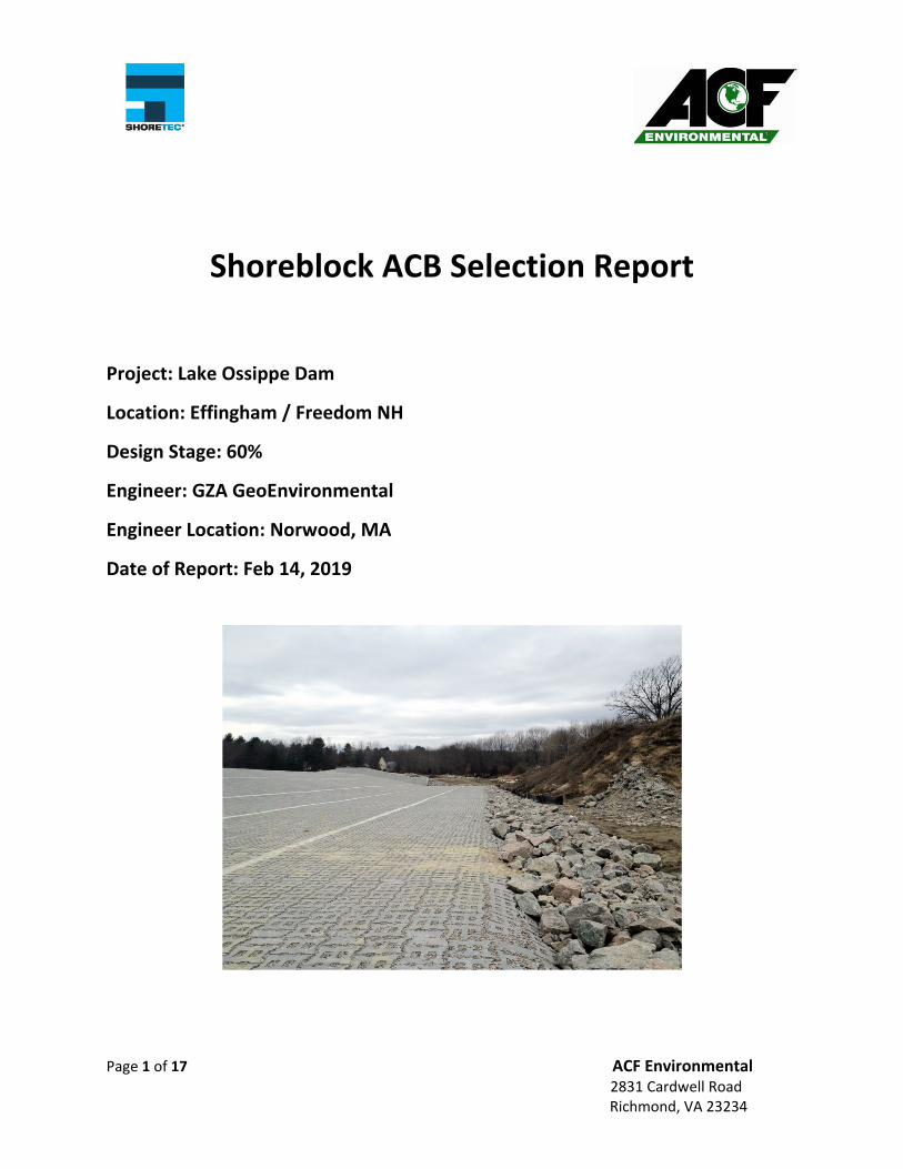
Shoreblock ACB Selection Report
Project: Lake Ossippe Dam
Location: Effingham / Freedom NH
Design Stage: 60%
Engineer: GZA GeoEnvironmental
Engineer Location: Norwood, MA
Date of Report: Feb 14, 2019
Page 2 of 17 ACF Environmental 2831 Cardwell Road Richmond, VA 23234
Executive Summary
Based upon the information provided to Shoretec LLC/ ACF Environmental for the Lake Ossipee Dam use of the
Shoreblock 475 OCT is recommended for this project to protect the left dam abutment from overtopping flows.
This recommendation is based on analysis of the Factor of Safety (FOS) by the CSU method as well as on hydraulic
Jump stability analysis with the information provided. Details of both of these analyses are outlined in this report.
Design Overview
The following report is provided by Shoretec LLC / ACF Environmental as a guide to assist in the proper ACB
selection, installation details and product specification for the referenced product(s). This report utilizes ASTM
7276 & 7277 protocols for ACB testing and test data analysis as well as FOS calculations utilizing both the NCMA
(2010) and CSU FOS methods, which the designer will need to consider along with the appropriate regulatory
agencies which is applicable for this given project. Specifically, this design summary will look at both determining
the Factor of Safety (FOS) for the project as well as hydraulic jump stability analysis if applicable for the project.
Shoretec has a complete performance testing per ASTM 7276 and ASTM 7277 protocols of its ACB line as outlined
below:
Shoreloc Handplaced ACB Systems (Steady State Overtopping Testing)
Shoreblock Untapered ACB Systems (Steady State Overtopping Testing)
Shoreblock Tapered ACB Systems (Steady State Overtopping Testing and Hydraulic Jump Stability Testing
on 2:1 slope)
Shoreblock EPEC Tapered ACB Systems with 3‐D Stabilized Stone Drainage Layer Systems (Steady State
Overtopping Testing and Hydraulic Jump Stability Testing on 2:1 slope)
The untapered Shoreblock ACB systems are available in both open cell (OC) and closed cell (CC) options while the
tapered Shoreblock ACB systems are available in only the open cell (OCT) options. Selection of the final product
will rely on a combination of specific hydraulic conditions of the project and the desired finish the owner desires.
Any questions or comments about this report should be sent to Jim Nadeau [email protected] or by calling
207‐659‐6993
ASTM
The following is a list and brief description of each of the four ASTM standards relating to ACBs. Each of the
Standards cites references the Section number (D) and 4‐digit item code, and the intent is that the latest version of
each as amended and updated over time shall prevail in the protocols utilized in this report unless otherwise
stated directly.
ASTM D 6684 – Standard Specification for Materials and Manufacture of Articulating Concrete Block (ACB)
Revetment Systems
This standard provides the basic physical specifications and manufacturing strength targets for ACBs as a minimum
which will perform well and last in field applications. Additions and or changes may be made by the Engineer of
Record in the ACB project specification developed. A guide to selecting the geotextile, particularly in terms of
strength is also provided. Actual sizing of the AOS etc. of the geotextile can be accomplished in several acceptable
manners such as HEC‐23 guidance, AASHOT guidance for fabrics under riprap or any method deemed acceptable
by the Engineer of Record.
ASTM D 6884 – Standard Practice for Installation of Articulating Concrete Block (ACB) Revetment Systems
Page 3 of 17 ACF Environmental 2831 Cardwell Road Richmond, VA 23234
This standard covers the basic installation details for ACB systems. Specific installation details not covered in this
Standard Practice may be included in the ACB project specification on a project by project basis or at the desire of
the Engineer of Record.
ASTM D 7276 – Standard Guide for Analysis and Interpretation of Test Data for Articulating Concrete Block (ACB)
Revetment Systems in Open Channel Flow
ASTM D 7277 – Standard Test Method for Performance Testing of Articulating Concrete Block (ACB) Revetment
Systems for Hydraulic Stability in Open Channel Flow
These Standards (ASTM D 7276 & D 7277), are the most critical to ACB design and ensuring the correct hydraulic
design parameters are calculated and utilized in the Factor of Safety calculations as described later in this report.
The older FHWA references should never be utilized as several underlying errors in the determination of the test
hydraulic design parameters were corrected with these ASTM testing and analysis standards. Currently there is an
effort in progress to add language to ASTM D7276 & ASTM D 7277 which adds a definition to the determination of
“threshold of performance”. A brief rationale is presented below and Shoretec LLC/ ACF has included this new
definition as applicable in the ASTM analyses used to calculate the FOS values contained in this report.
New language is being proposed in both ASTM D 7276 and ASTM D 7277 pertaining to the determination of the
threshold of performance. The basic underlying assumption in the FOS calculations is that the only stabilizing force
acting upon the ACB block is gravity, specifically gravity normal to the slope. Cables restraining the blocks are not
accounted for in the FOS calculations nor are anchors. This needs to remain true during testing of ACB systems,
that is the ACB blocks can not be restrained in any fashion in the flume during the test, and at the point where
external restraint is applied, this needs to be deemed the threshold of performance if one of the other criteria
outlined in the ASTM standards (7276 & 7277) has not been met. Specifically, this restraint is addressed in the
requirement that during the testing at least one block in every other row of ACB units needs to be free floating.
This language ensures that an ACB system where the block is 4 feet wide is not tested as every block would be
physically restrained thus changing the results of the test and leading to erroneous FOS calculations. The same is
true for engagement of cables due to ACB block movement when tested on a stone drainage layer. The ACB blocks
have been shown to move to the point where the cables become engaged, thus restraining the blocks and the
onset or erosion has not yet occurred. Some manufacturers chose to ignore this cable engagement and argue that
ASTM does not specifically state this and are resisting the change to ASTM Standards at every step of the process.
Shoretec LLC / ACF Environmental has embraced these definitions as conservative and appropriate for the industry
and incorporated them into our analysis of hydraulic ACB test data for our products. Specifically, a limit of three
consecutive station measurements which exceed 0.625 inches in vertical displacement of the ACB blocks in the
flume shall be deemed the threshold of performance for that given system.
Extrapolation of ACB hydraulic design values follow the similitude method which extrapolates design values for
heavier ACBs with the same footprint as the lighter tested ACB block.
Factor of Safety (FOS) Calculations
The FOS values used to determine applicability of ACBs for given project conditions are calculated using two
industry accepted methods (NCMA and CSU) which are described in detail below. FOS targets of 1.5 are typical
standards for ACB applications, however other target values may be utilized. It is the responsibility of the Engineer
of Record to set either alone or in conjunction with the appropriate regulatory agency a project specific FOS.
Ranges of FOS typically seen are a low of 1.25 up to a high of 2.0.
Page 4 of 17 ACF Environmental 2831 Cardwell Road Richmond, VA 23234
NCMA Method
The NCMA method is the latest incarnation of the original FOS method developed by Clopper in the late 1980s
because of the newly obtained hydraulic data from the FHWA 1988 and 1989 studies. There was a need to
incorporate the test results into a design tool to be used for field applications. The following are a summary of the
basic underlying approach and assumptions used in the original FOS method and that remain in the current NCMA
Method.
1. Lift and Drag forces (FD and FL) were assumed to be equal. FD is calculated based on a block projection
height Z which is set at 0.5 inches for untapered ACB units and 0 inches for tapered ACB units 2. Moment arms were drawn up in this method with the flow of the water being diagonal on the ACB block.
This fixed the failure rotation point at the downstream corner of the ACB block.
3. This method was developed for untapered ACB units and later applied to tapered ACB units
Some of the limitations of the NCMA method became obvious when it was used for determining the FOS of
tapered ACB systems, which clearly was not the intent when the method was first developed. Some of the results
from the NCMA method in determining the FOS for tapered systems are described below
1. Velocity has no impact on the calculated FOS
2. Weight of the ACB block has no impact on the calculated FOS
3. Moment Arms have no impact on the calculated FOS
4. Calculated FOS relies only on slope (bed and side) and design shear
The assumption of the lift forces and drag forces being equal was made for this method because there were more
unknowns than equations that could be written at the time leading to an unsolvable situation. It is obvious from
the above noted results, this assumption may not have been the best to make in the beginning or at least it
appears to not be valid when applied to tapered ACB systems. These observations led to the development of the
CSU method developed in 2010 by Dr Amanda L Cox and Dr. Christopher I Thornton.
CSU Method
The CSU FOS Method was developed to overcome the shortcomings made in the assumptions in the NCMA FOS
method. Specifically, the CSU Method
1. Treats Lift and Drag Forces independently
2. Allows block rotation around 4 natural pivot points (M,O,P & BED with BED being same point as P with 0
degree side slope)
3. Direction of flow across surface of block matters in defining moment arms
The assumption of FL and FD being equal was analyzed in the PhD dissertation of Dr. Amanda L Cox and it was
found that this assumption was true up until velocities of around 10 to 12 ft/sec were attained. Therefore, it is
recommended that the FOS for an ACB system be determined using the CSU Method, however in low velocity
(typically stream or canal applications) the NCMA method performs adequately. The required hydraulic data for
both the NCMA and CSU FOS methods can be determined from the same flume test data, it simply involves a
slightly different manipulation of the threshold shear and velocity values determined in the flume test at the
threshold of performance.
Page 5 of 17 ACF Environmental 2831 Cardwell Road Richmond, VA 23234
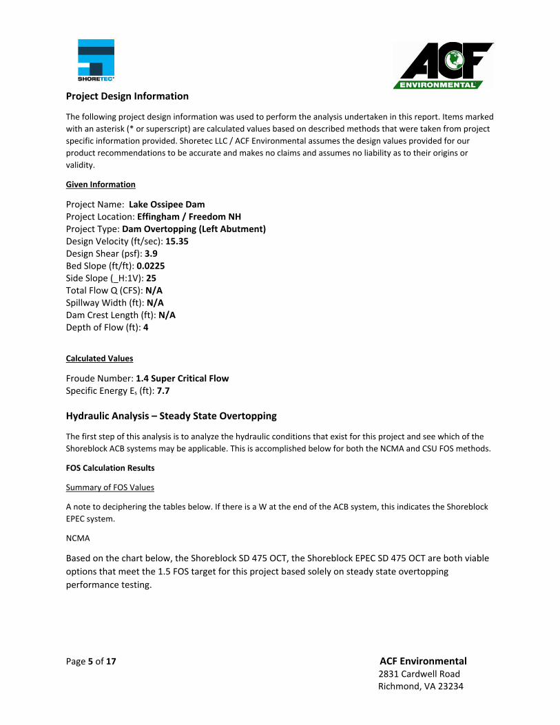
Project Design Information
The following project design information was used to perform the analysis undertaken in this report. Items marked
with an asterisk (* or superscript) are calculated values based on described methods that were taken from project
specific information provided. Shoretec LLC / ACF Environmental assumes the design values provided for our
product recommendations to be accurate and makes no claims and assumes no liability as to their origins or
validity.
Given Information
Project Name: Lake Ossipee Dam Project Location: Effingham / Freedom NH Project Type: Dam Overtopping (Left Abutment) Design Velocity (ft/sec): 15.35 Design Shear (psf): 3.9 Bed Slope (ft/ft): 0.0225 Side Slope (_H:1V): 25 Total Flow Q (CFS): N/A Spillway Width (ft): N/A Dam Crest Length (ft): N/A Depth of Flow (ft): 4
Calculated Values
Froude Number: 1.4 Super Critical Flow Specific Energy Es (ft): 7.7
Hydraulic Analysis – Steady State Overtopping
The first step of this analysis is to analyze the hydraulic conditions that exist for this project and see which of the
Shoreblock ACB systems may be applicable. This is accomplished below for both the NCMA and CSU FOS methods.
FOS Calculation Results
Summary of FOS Values
A note to deciphering the tables below. If there is a W at the end of the ACB system, this indicates the Shoreblock
EPEC system.
NCMA
Based on the chart below, the Shoreblock SD 475 OCT, the Shoreblock EPEC SD 475 OCT are both viable
options that meet the 1.5 FOS target for this project based solely on steady state overtopping
performance testing.
Page 6 of 17 ACF Environmental 2831 Cardwell Road Richmond, VA 23234
CSU
When determining FOS for an ACB system using the CSU method, four values are returned for each
system evaluated. The lowest FOS value is chosen as this is the controlling predicted failure mode.
Typically this value is around point P (SFP), however all values are examined.
Based on the chart below, any of the Shoreblock tapered or Shoreblock EPEC tapered products are all
viable options that meet the 1.5 FOS target for this project based solely on steady state overtopping
performance testing.
SD 475 OCT 6.40
SD 600 OCT 7.56
SD 800 OCT 7.45
SD 900 OCT 9.16
SD 475 OCTW 7.46
SD 600 OCTW 9.21
SD 800 OCTW 10.67
SD 900 OCTW 11.31
SD Series Tapered Open Cell
SFO SFP SFM SFBEDSD 475 OCT 15.36 7.15 9.37 7.16
SD 600 OCT 18.34 8.19 10.84 8.19
SD 800 OCT 19.54 8.46 11.29 8.46
SD 900 OCT 20.86 9.25 12.27 9.25
SD 475 OCTW 15.15 7.11 9.29 7.12
SD 600 OCTW 18.13 8.14 10.77 8.15
SD 800 OCTW 19.34 8.42 11.22 8.42
SD 900 OCTW 20.67 9.21 12.21 9.22
SD Series Tapered Open Cell
Page 7 of 17 ACF Environmental 2831 Cardwell Road Richmond, VA 23234
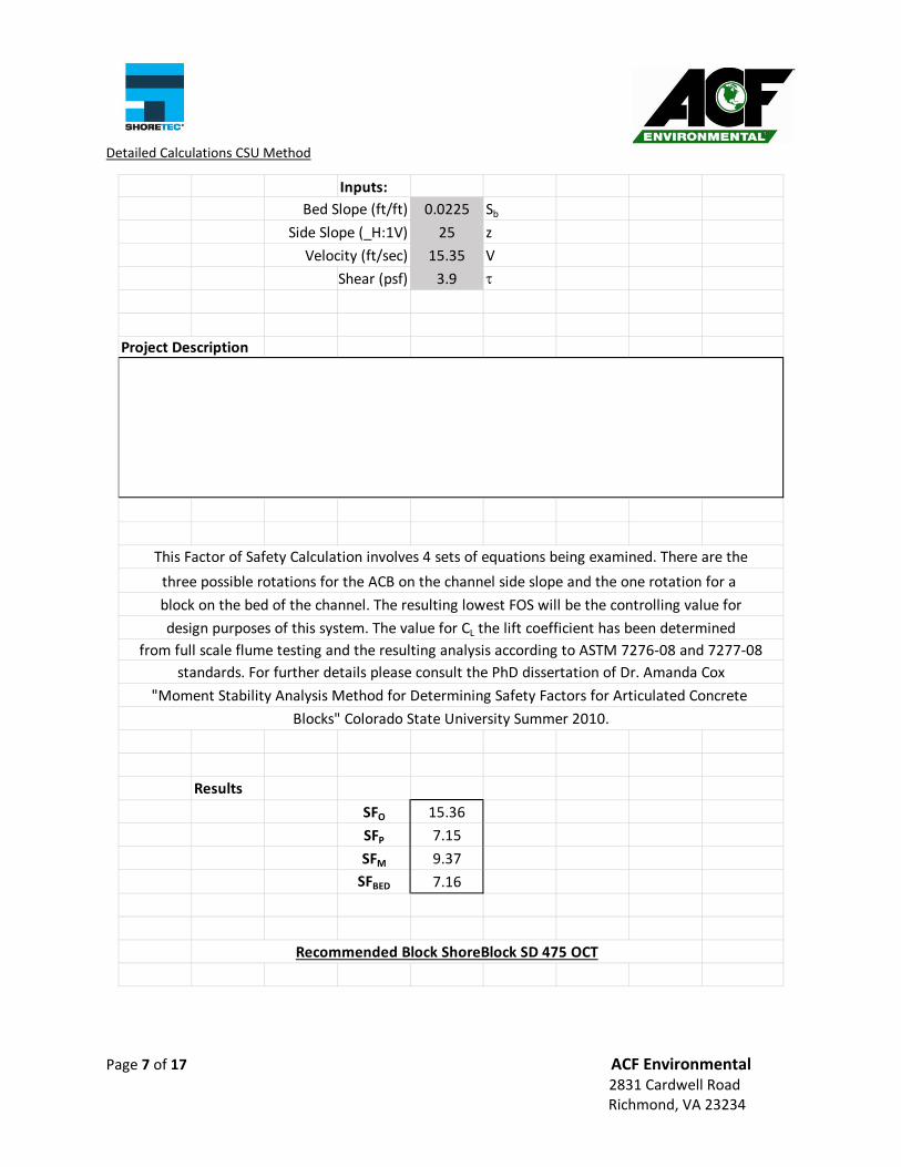
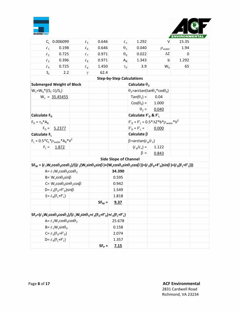
Detailed Calculations CSU Method
Inputs:
Bed Slope (ft/ft) 0.0225 Sb
Side Slope (_H:1V) 25 z
Velocity (ft/sec) 15.35 V
Shear (psf) 3.9
Project Description
Results
SFO 15.36
SFP 7.15
SFM 9.37
SFBED 7.16
This Factor of Safety Calculation involves 4 sets of equations being examined. There are the
three possible rotations for the ACB on the channel side slope and the one rotation for a
block on the bed of the channel. The resulting lowest FOS will be the controlling value for
Blocks" Colorado State University Summer 2010.
Recommended Block ShoreBlock SD 475 OCT
standards. For further details please consult the PhD dissertation of Dr. Amanda Cox
"Moment Stability Analysis Method for Determining Safety Factors for Articulated Concrete
design purposes of this system. The value for CL the lift coefficient has been determined
from full scale flume testing and the resulting analysis according to ASTM 7276‐08 and 7277‐08
Page 8 of 17 ACF Environmental 2831 Cardwell Road Richmond, VA 23234
SFM = (l 7Wscos0cos2)/((l 1(Wssin0sin)+(Wscos0sin2cos))+(l 3(FD+F'D)sin)+(l 8(FL+F'L)))A= l 7Wscos0cos2 34.390
B= Wssin0sin 0.595
C= Wscos0sin2cos 0.942
D= l 3(FD+F'D)sin 1.549
E= l 8(FL+F'L) 1.818
SFM = 9.37
SFP=(l 2Wscos0cos2)/(l 1Wssin0+l 3(FD+F'D)+l 4(FL+F'L)A= l 2Wscos0cos2 25.678
B= l 1Wssin0 0.158
C= l 3(FD+F'D) 2.074
D= l 4(FL+F'L) 1.357
SFP = 7.15
Side Slope of Channel
Step‐by‐Step Calculations
Page 9 of 17 ACF Environmental 2831 Cardwell Road Richmond, VA 23234
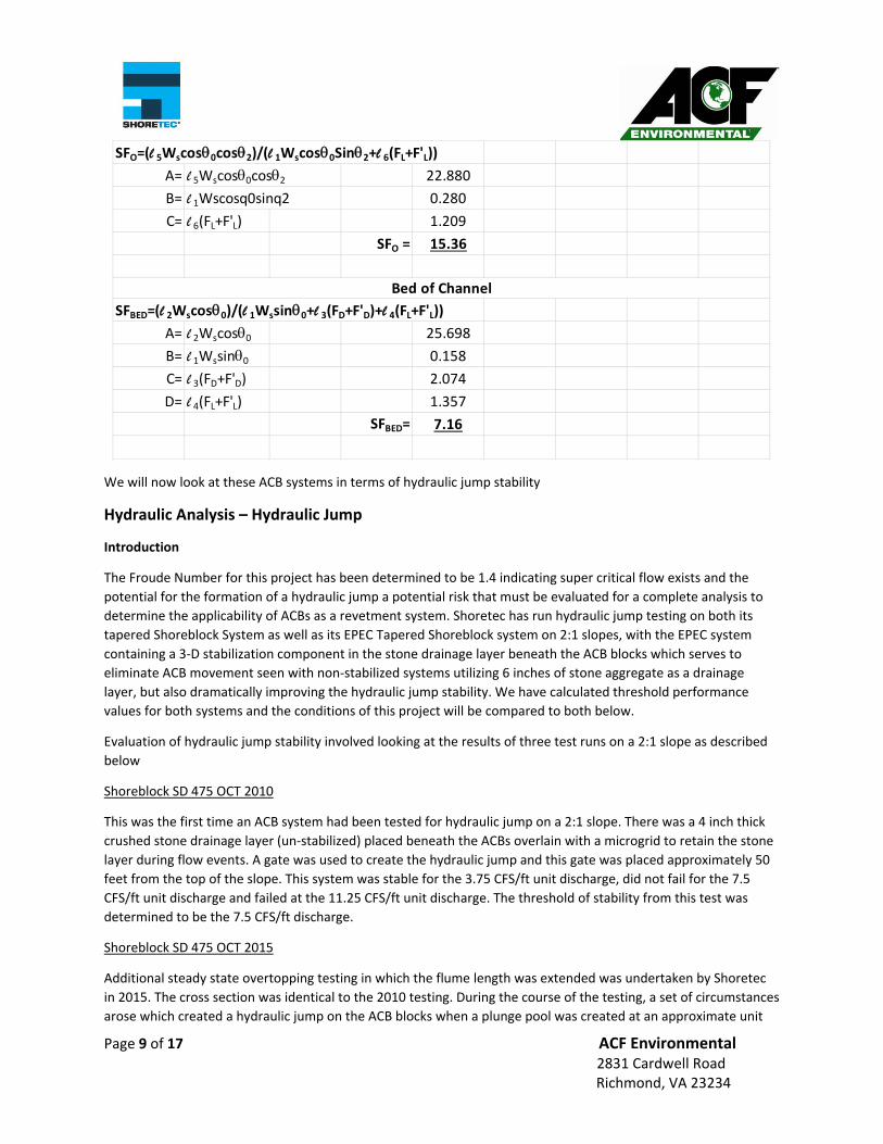
We will now look at these ACB systems in terms of hydraulic jump stability
Hydraulic Analysis – Hydraulic Jump
Introduction
The Froude Number for this project has been determined to be 1.4 indicating super critical flow exists and the
potential for the formation of a hydraulic jump a potential risk that must be evaluated for a complete analysis to
determine the applicability of ACBs as a revetment system. Shoretec has run hydraulic jump testing on both its
tapered Shoreblock System as well as its EPEC Tapered Shoreblock system on 2:1 slopes, with the EPEC system
containing a 3‐D stabilization component in the stone drainage layer beneath the ACB blocks which serves to
eliminate ACB movement seen with non‐stabilized systems utilizing 6 inches of stone aggregate as a drainage
layer, but also dramatically improving the hydraulic jump stability. We have calculated threshold performance
values for both systems and the conditions of this project will be compared to both below.
Evaluation of hydraulic jump stability involved looking at the results of three test runs on a 2:1 slope as described
below
Shoreblock SD 475 OCT 2010
This was the first time an ACB system had been tested for hydraulic jump on a 2:1 slope. There was a 4 inch thick
crushed stone drainage layer (un‐stabilized) placed beneath the ACBs overlain with a microgrid to retain the stone
layer during flow events. A gate was used to create the hydraulic jump and this gate was placed approximately 50
feet from the top of the slope. This system was stable for the 3.75 CFS/ft unit discharge, did not fail for the 7.5
CFS/ft unit discharge and failed at the 11.25 CFS/ft unit discharge. The threshold of stability from this test was
determined to be the 7.5 CFS/ft discharge.
Shoreblock SD 475 OCT 2015
Additional steady state overtopping testing in which the flume length was extended was undertaken by Shoretec
in 2015. The cross section was identical to the 2010 testing. During the course of the testing, a set of circumstances
arose which created a hydraulic jump on the ACB blocks when a plunge pool was created at an approximate unit
SFO=(l 5Wscos0cos2)/(l 1Wscos0Sin2+l 6(FL+F'L))A= l 5Wscos0cos2 22.880
B= l 1Wscosq0sinq2 0.280
C= l 6(FL+F'L) 1.209
SFO = 15.36
SFBED=(l 2Wscos0)/(l 1Wssin0+l 3(FD+F'D)+l 4(FL+F'L))A= l 2Wscos0 25.698
B= l 1Wssin0 0.158
C= l 3(FD+F'D) 2.074
D= l 4(FL+F'L) 1.357
SFBED= 7.16
Bed of Channel
Page 10 of 17 ACF Environmental 2831 Cardwell Road Richmond, VA 23234
discharge of 11 CFS/ft which failed the system. This helped confirm the results seen in the 2010 hydraulic jump
testing.
Shoreblock EPEC SD 475 OCT 2017
The Shoreblock EPEC system was developed to address stone movement beneath the ACBs seen when the
drainage layer was increased from 4 inches to 6 inches. This increase was largely due to the question of how
uniformly can a 4 inch thickness of #57 stone be deployed in a large application in the field. The logic being if a 6
inch thick stone layer was deployed it would insure a minimum of 4 inches was realized in the field. Test results of
a 6 inch unstabilized stone layer showed excessive ACB movement thus the EPEC system was developed to
stabilize the stone and eliminate the movement of the ACB blocks under flow conditions. Additionally, it was
hypothesized that stabilization of the stone might improve hydraulic jump stability. Testing of the EPEC system
proved to eliminate the ACB movement and increased hydraulic jump stability from a unit discharge of 7.5 CFS/ft
with the unstabilized system to 25 CFS/ft with the EPEC system
Hydraulic Jump Analysis
The hydraulic jump analysis for ACB systems involves calculating the specific energy (Es) for the project conditions
and comparing this value to threshold values determined from the threshold performance values determined in
the testing. Specific energy is calculated as follows
𝐸𝑉2𝑔
𝑑
Where:
V – Velocity (ft/sec) d – Flow Depth (ft) g – Gravitational Constant 32.2 ft/s2
The Table below shows the results of this analysis for both the Shoreblock Tapered and Shoreblock EPEC systems
ACB System Calculated Es Threshold Es
Shoreblock Tapered ACB 7.7 8.07
Shoreblock EPEC Tapered ACB 7.7 17.48
Based upon these hydraulic jump stability results the Shoreblock SD 475 OCT tapered system would be
recommended. As an aside here, there are some untapered ACB blocks that meet the FOS target, however they
were not considered in this analysis due to the existence of super critical flow conditions and the lack of hydraulic
jump performance testing with untapered ACB systems.
Product Recommendation(s)
Combining the FOS calculations (using the CSU method as velocities are above 12 ft/sec) and the hydraulic jump
stability analysis the Shoreblock 475 OCT system is recommended for this application. The selection of the
corresponding geotextile is left to the design engineer and should be based on guidance provided in ASTM 6684 as
well as other industry accepted methods which are typically based on the subgrade soils sieve analysis.
Page 11 of 17 ACF Environmental 2831 Cardwell Road Richmond, VA 23234
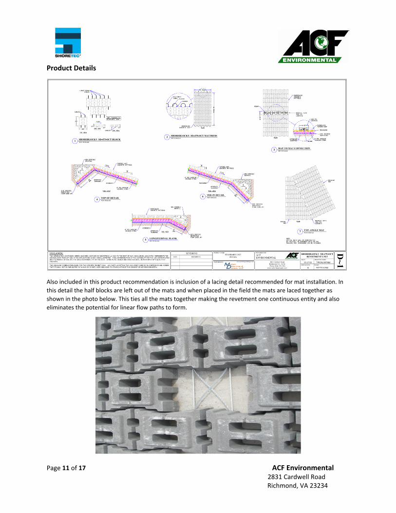
Product Details
Also included in this product recommendation is inclusion of a lacing detail recommended for mat installation. In
this detail the half blocks are left out of the mats and when placed in the field the mats are laced together as
shown in the photo below. This ties all the mats together making the revetment one continuous entity and also
eliminates the potential for linear flow paths to form.
Page 12 of 17 ACF Environmental 2831 Cardwell Road Richmond, VA 23234
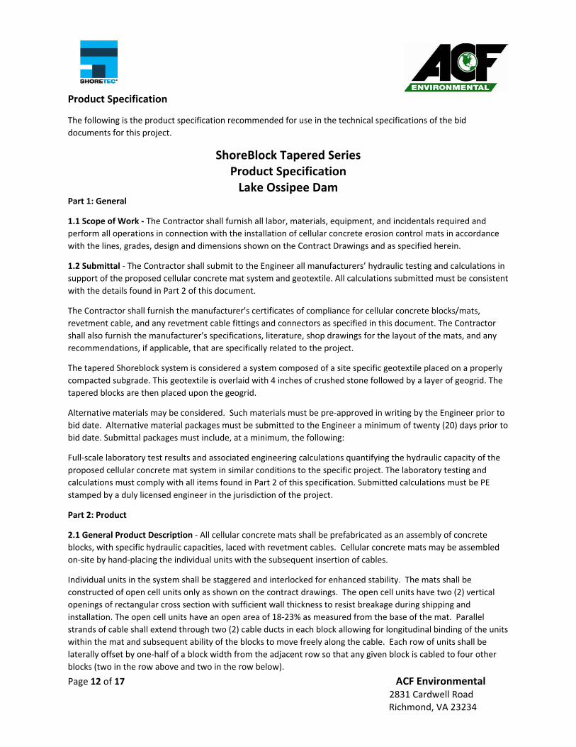
Product Specification
The following is the product specification recommended for use in the technical specifications of the bid
documents for this project.
ShoreBlock Tapered Series Product Specification Lake Ossipee Dam
Part 1: General
1.1 Scope of Work ‐ The Contractor shall furnish all labor, materials, equipment, and incidentals required and
perform all operations in connection with the installation of cellular concrete erosion control mats in accordance
with the lines, grades, design and dimensions shown on the Contract Drawings and as specified herein.
1.2 Submittal ‐ The Contractor shall submit to the Engineer all manufacturers’ hydraulic testing and calculations in
support of the proposed cellular concrete mat system and geotextile. All calculations submitted must be consistent
with the details found in Part 2 of this document.
The Contractor shall furnish the manufacturer's certificates of compliance for cellular concrete blocks/mats,
revetment cable, and any revetment cable fittings and connectors as specified in this document. The Contractor
shall also furnish the manufacturer's specifications, literature, shop drawings for the layout of the mats, and any
recommendations, if applicable, that are specifically related to the project.
The tapered Shoreblock system is considered a system composed of a site specific geotextile placed on a properly
compacted subgrade. This geotextile is overlaid with 4 inches of crushed stone followed by a layer of geogrid. The
tapered blocks are then placed upon the geogrid.
Alternative materials may be considered. Such materials must be pre‐approved in writing by the Engineer prior to
bid date. Alternative material packages must be submitted to the Engineer a minimum of twenty (20) days prior to
bid date. Submittal packages must include, at a minimum, the following:
Full‐scale laboratory test results and associated engineering calculations quantifying the hydraulic capacity of the
proposed cellular concrete mat system in similar conditions to the specific project. The laboratory testing and
calculations must comply with all items found in Part 2 of this specification. Submitted calculations must be PE
stamped by a duly licensed engineer in the jurisdiction of the project.
Part 2: Product
2.1 General Product Description ‐ All cellular concrete mats shall be prefabricated as an assembly of concrete
blocks, with specific hydraulic capacities, laced with revetment cables. Cellular concrete mats may be assembled
on‐site by hand‐placing the individual units with the subsequent insertion of cables.
Individual units in the system shall be staggered and interlocked for enhanced stability. The mats shall be
constructed of open cell units only as shown on the contract drawings. The open cell units have two (2) vertical
openings of rectangular cross section with sufficient wall thickness to resist breakage during shipping and
installation. The open cell units have an open area of 18‐23% as measured from the base of the mat. Parallel
strands of cable shall extend through two (2) cable ducts in each block allowing for longitudinal binding of the units
within the mat and subsequent ability of the blocks to move freely along the cable. Each row of units shall be
laterally offset by one‐half of a block width from the adjacent row so that any given block is cabled to four other
blocks (two in the row above and two in the row below).
Page 13 of 17 ACF Environmental 2831 Cardwell Road Richmond, VA 23234
Each block shall incorporate interlocking surfaces that minimize lateral displacement of the blocks within the mats
when they are lifted by the longitudinal revetment cables. The interlocking surfaces must not protrude beyond the
perimeter of the blocks to such an extent that they reduce the flexibility or articulation capability of the cellular
mats or become damaged or broken when the mats are lifted during shipment or placement. Once the mats are in
place, the interlocking surfaces shall minimize the lateral displacement of the blocks even if the cables should
become damaged or removed. The mats must be able to flex a minimum of 18° between any given row or column
of blocks in the uplift direction and a minimum of 45° in the downward direction.
The cables inserted into the mats shall form lifting loops at one end of the mat with the corresponding cable ends
spliced together to form a lifting loop at the other end of the mat. The cables shall be inserted after sufficient time
has been allowed for the concrete to complete the curing process.
The cellular concrete mats shall be placed on a filter fabric as specified herein. Under no circumstances shall the
filter fabric be affixed (i.e. chemically bonded to the blocks) to the mattress in a manner in which would jeopardize
the functionality of the filter fabric. Specifically, the filter fabric shall be independent of the block system.
2.2 Independent Testing – All ACB systems shall be independently tested by a facility experienced in performing
such tests. All testing and the interpretation of the test data shall conform to the following ASTM standards:
ASTM D7277 Standard Test Method for Performance Testing of Articulating Concrete Block (ACB) Revetment
Systems for Hydraulic Stability in Open Channel Flow.
ASTM D7276 Standard Guide for Analysis and Interpretation of Test Data for Articulating Concrete Block (ACB)
Revetment Systems
In addition to the above guidance standards, the following specific testing, data analysis and FOS computation
requirements shall be met:
A. In the test flume data analysis report, charts showing ACB movement as measured by bed elevation
change from the original conditions in the flume before testing commenced will be provided for each flow
condition tested.
B. The threshold of performance shall have been met after any flow condition if more than three
consecutive station measurements show a 0.625 inch movement in the ACB blocks. The actual point will
be determined by moving one station upstream from the first point in this series where three or more
consecutive measurements exceeded the 0.625 inch value.
C. Hydraulic jump testing of the proposed ACB system shall have been conducted on a 2:1 slope (minimum).
The creation of the jump shall have dissipated a minimum of 50% of the incoming specific energy and
shall have been run for a minimum duration of 1 hour at steady state conditions.
D. No ACB blocks lighter than tested under hydraulic jump conditions will be allowed
E. The hydraulic jump testing must have been conducted on a cross section similar to that of this project (i.e.
compacted subgrade, geotextile, stone drainage layer, geogrid then ACB blocks.
The design of the cellular concrete mats shall be in accordance with the equations found in the PhD dissertation of
Dr. Amanda Cox “Moment Stability Analysis Method for Determining Safety Factors for Articulating Concrete
Blocks” or the NCMA ACB Design Manual (2010) and shall meet a minimum FOS of 1.5 or when calculated around
Point P using the CSU equations. Orientation of the ACBs as installed in the field shall be the same as the
orientation they were performance tested in the flume.
The analysis shall be performed based upon the stability of the mat due to gravity forces alone, neglecting
conservative forces added by cabling, mechanical anchorage, contact with adjacent blocks, or other restraints not
Page 14 of 17 ACF Environmental 2831 Cardwell Road Richmond, VA 23234
attributable to gravity‐based forces. The analysis must account for a 0.0‐inch block projection. Hydraulic jump
analysis based on the incoming specific energy shall also be performed and supported by appropriate test results.
Other factors that must be met for the ACB test results include:
1. For design velocities less than 20 ft/sec vertical drop of test flume must be a minimum of 10 feet.
2. All ACB’s must be tested on a minimum 2H:1V embankment slope. 3. For design velocities greater than 20 ft/sec vertical drop of the test flume section must be
greater than 20 feet. 4. Hydraulic jump test data provided on a 2:1 slope. 5. Projection height for tapered blocks is set to 0.0”. 6. Reported shear values can only be extrapolated with in the same “family” (having identical foot
print in terms of both shape and area) and from lighter to heavier blocks. This also holds for the hydraulic jump analysis (no blocks lighter than tested)
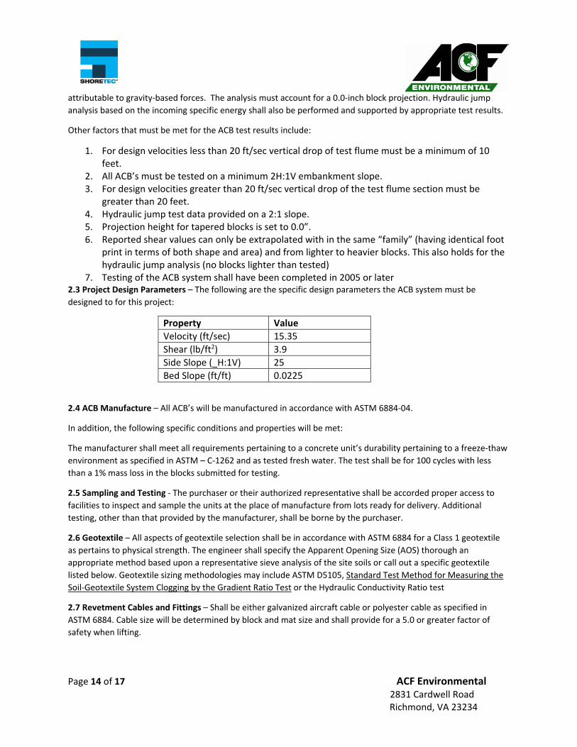
7. Testing of the ACB system shall have been completed in 2005 or later 2.3 Project Design Parameters – The following are the specific design parameters the ACB system must be
designed to for this project:
Property Value
Velocity (ft/sec) 15.35
Shear (lb/ft2) 3.9
Side Slope (_H:1V) 25
Bed Slope (ft/ft) 0.0225
2.4 ACB Manufacture – All ACB’s will be manufactured in accordance with ASTM 6884‐04.
In addition, the following specific conditions and properties will be met:
The manufacturer shall meet all requirements pertaining to a concrete unit’s durability pertaining to a freeze‐thaw
environment as specified in ASTM – C‐1262 and as tested fresh water. The test shall be for 100 cycles with less
than a 1% mass loss in the blocks submitted for testing.
2.5 Sampling and Testing ‐ The purchaser or their authorized representative shall be accorded proper access to
facilities to inspect and sample the units at the place of manufacture from lots ready for delivery. Additional
testing, other than that provided by the manufacturer, shall be borne by the purchaser.
2.6 Geotextile – All aspects of geotextile selection shall be in accordance with ASTM 6884 for a Class 1 geotextile
as pertains to physical strength. The engineer shall specify the Apparent Opening Size (AOS) thorough an
appropriate method based upon a representative sieve analysis of the site soils or call out a specific geotextile
listed below. Geotextile sizing methodologies may include ASTM D5105, Standard Test Method for Measuring the
Soil‐Geotextile System Clogging by the Gradient Ratio Test or the Hydraulic Conductivity Ratio test
2.7 Revetment Cables and Fittings – Shall be either galvanized aircraft cable or polyester cable as specified in
ASTM 6884. Cable size will be determined by block and mat size and shall provide for a 5.0 or greater factor of
safety when lifting.
Page 15 of 17 ACF Environmental 2831 Cardwell Road Richmond, VA 23234
Polyester Cable Specific Details –
Revetment cable shall be constructed of high tenacity, low elongating, and continuous filament polyester fibers.
Cable shall consist of a core construction comprised of parallel fibers contained within an outer jacket or cover.
The weight of the parallel core shall be between 65% to 70% of the total weight of the cable. The revetment cable
Elongation requirements specified below are based upon stabilized new, dry cable. Stabilization refers to a
process in which the cable is cycled fifty (50) times between a load corresponding to 200D2 and a load equal to
10%, 20% or 30% of the cable's approximate average breaking strength. Relevant elongation values are as shown
in the table below. The tolerance on these values is + 5%.
ELASTIC ELONGATION
at Percentage of Break Strength
10% 20% 30%
0.6 1.4 2.2
The revetment cable shall exhibit resistance to most concentrated acids, alkalis and solvents. Cable shall be
impervious to rot, mildew and degradation associated with marine organisms. The materials used in the
construction of the cable shall not be affected by continuous immersion in fresh or salt water.
Selection of cable and fittings shall be made in a manner that insures a safe design factor for mats being lifted from
both ends, thereby forming a catenary. Consideration shall be taken for the bending of the cables around hooks or
pins during lifting. Revetment cable splicing fittings shall be selected so that the resultant splice shall provide a
minimum of 60% of the minimum rated cable strength. Fittings such as sleeves and stops shall be aluminum and
washers shall be galvanized steel unless otherwise shown on the Contract Drawings.
2.8 Field Installation – Field installation shall be in accordance with ASTM 6884 unless noted below.
Shoreblock SD 475 OCT tapered blocks will be installed on top of a 4” thick AASHTO #57 angular open graded
crushed stone. The section shall consist of properly compacted subgrade, the geotextile, stone drainage layer,
geogrid followed by the ACB’s. The open areas of the ACB’s can be filled with #57 stone (or similar).
Termination trenches shall be backfilled with 4000 psi non shrink grout or a material specifically called out by the
design engineer. Gaps in the revetment system, whether end to end, side to side or around a radius greater than
2” shall be filled with 4000 psi non shrink grout.
Page 16 of 17 ACF Environmental 2831 Cardwell Road Richmond, VA 23234
ACB mats shall be laterally laced with a 20 MM polyester cable as shown in the ACB details on contract plans. Once
laced, the voids shall be filled with 4,000 psi grout. Under no circumstances will half blocks or any multiples there
of and pig tails be allowed. The mats must be connected to each other side‐to‐side with an integral cable laced
through the cable ducts of the ACB blocks.
2.9 Mat Sizes – Mat sizes shall be determined during the layout process which is completed once a purchase order
for the project has been issued by the owner or contractor. Mat size shall not exceed 8’ in width or 40’ in length
unless special provisions are made ahead of time with the design engineer on a specific project. Mat sizes shall be
selected to minimize both freight costs and the amount of grout needed for finishing of the revetment system.
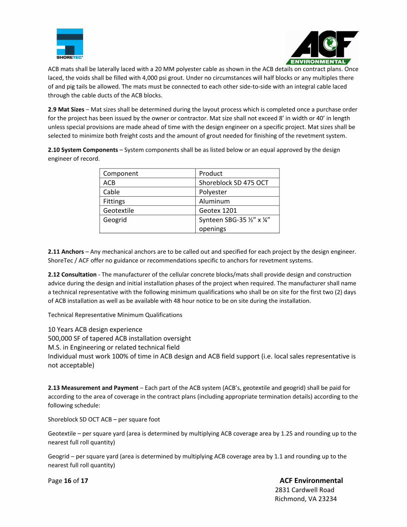
2.10 System Components – System components shall be as listed below or an equal approved by the design
engineer of record.
Component Product
ACB Shoreblock SD 475 OCT
Cable Polyester
Fittings Aluminum
Geotextile Geotex 1201
Geogrid Synteen SBG‐35 ½” x ¼” openings
2.11 Anchors – Any mechanical anchors are to be called out and specified for each project by the design engineer.
ShoreTec / ACF offer no guidance or recommendations specific to anchors for revetment systems.
2.12 Consultation ‐ The manufacturer of the cellular concrete blocks/mats shall provide design and construction
advice during the design and initial installation phases of the project when required. The manufacturer shall name
a technical representative with the following minimum qualifications who shall be on site for the first two (2) days
of ACB installation as well as be available with 48 hour notice to be on site during the installation.
Technical Representative Minimum Qualifications
10 Years ACB design experience 500,000 SF of tapered ACB installation oversight M.S. in Engineering or related technical field Individual must work 100% of time in ACB design and ACB field support (i.e. local sales representative is not acceptable)
2.13 Measurement and Payment – Each part of the ACB system (ACB’s, geotextile and geogrid) shall be paid for
according to the area of coverage in the contract plans (including appropriate termination details) according to the
following schedule:
Shoreblock SD OCT ACB – per square foot
Geotextile – per square yard (area is determined by multiplying ACB coverage area by 1.25 and rounding up to the
nearest full roll quantity)
Geogrid – per square yard (area is determined by multiplying ACB coverage area by 1.1 and rounding up to the
nearest full roll quantity)
Page 17 of 17 ACF Environmental 2831 Cardwell Road Richmond, VA 23234
Test Report
A copy of the Shoreblock SD 475 OCT test report from CSU is available upon request. It was omitted in this report
due to the voluminous nature (100 plus pages).
References
ASTM 6684 ‐ Standard Specification for Materials and Manufacture of Articulating Concrete Block (ACB) Revetment
Systems
ASTM 6884 ‐ Standard Practice for Installation of Articulating Concrete Block (ACB) Revetment Systems
ASTM 7276 ‐ Standard Guide for Analysis and Interpretation of Test Data for Articulating Concrete Block (ACB)
Revetment Systems in Open Channel Flow
ASTM 7277 ‐ Standard Test Method for Performance Testing of Articulating Concrete Block (ACB) Revetment
Systems for Hydraulic Stability in Open Channel Flow
NCMA 2010 – Design Manual for Articulating Concrete Block Revetment Systems
NEH Part 628 Chapter 54 – National Engineering Handbook Part 628 Dams Chapter 54 ACB Armored Spillways
(DRAFT)
Cox, Amanda L ‐ Moment Stability Analysis Method for Determining Safety Factors for Articulating Concrete Blocks
Cox, Amanda L – Articulated Concrete Block Stability Analysis for Embankment Overtopping Conditions
HEC‐23 – ACB & Filter Design
Bureau of Reclamation – Hydraulic Design of Stilling Basins and Energy Dissipators 1958