xterior insulation and finish systems CMHC offers a wide range of housing-related information. For details, contact your local CMHC office or call 1 800 668-2642. Cette publication est aussi disponible en français sous le titre : Guide des règles de l’art — Systèmes d’isolation des façades avec enduit (SIFE), 63568 e Best practice guide building technology CMHC acknowledges the financial contribution of Public Works Government Services Canada toward the publication of this Guide.
Transcript
xterior insulation
and finish systems
CMHC offers a wide range of housing-related information.For details, contact your local CMHC office or call 1 800 668-2642.
Cette publication est aussi disponible en français sous le titre :Guide des règles de l’art — Systèmes d’isolation des façadesavec enduit (SIFE), 63568
eBest practice guide
building technology
CMHC acknowledges the financial
contribution of Public Works
Government Services Canada toward
the publication of this Guide.
CMHC—Home to Canadians
Canada Mortgage and Housing Corporation (CMHC) isthe Government of Canada’s national housing agency.Wehelp Canadians gain access to a wide choice of quality,affordable homes.
Our mortgage loan insurance program has helped manyCanadians realize their dream of owning a home.We providefinancial assistance to help Canadians most in need to gainaccess to safe, affordable housing.Through our research,we encourage innovation in housing design and technology,community planning, housing choice and finance.We also work inpartnership with industry and other Team Canada members tosell Canadian products and expertise in foreign markets, therebycreating jobs for Canadians here at home.
We offer a wide variety of information products to consumersand the housing industry to help them make informedpurchasing and business decisions.With Canada’s mostcomprehensive selection of information about housing andhomes, we are Canada’s largest publisher of housing information.
In everything that we do, we are helping to improve the qualityof life for Canadians in communities across this country.We arehelping Canadians live in safe, secure homes. CMHC is hometo Canadians.
Canadians can easily access our information through retailoutlets and CMHC’s regional offices.
You can also reach us by phone at 1 800 668-2642 (outside Canada call (613) 748-2003)By fax at 1 800 245-9274 (outside Canada (613) 748-2016)
To reach us online, visit our home page at www.cmhc.ca
Exterior Insulation and Finish Systems (EIFS)
National Library of Canada cataloguing in publication
Main entry under title :
Exterior insulation and finish systems (EIFS)
(Best practice guide, building technology)Issued also in French under title: Systèmes d’isolation des façades avec enduit (SIFE).Includes bibliographical references.ISBN 0-660-19318-3Cat. no. NH15-424/2004E
1. Exterior insulation and finish systems – Design and construction.2. Insulation (Heat).I. Canada Mortgage and Housing Corporation.II. Series.
Canada Mortgage and HousingCorporation, the federal government’s housing agency, is responsible foradministering the National Housing Act.
This legislation is designed to aid in the improvement of housing and livingconditions in Canada. As a result, the corporation has interests in all aspectsof housing and urban growth and development.
Under Part IX of this Act, the Government of Canada provides fundsto CMHC to conduct research into the social, economic, and technicalaspects of housing and related fields, and to undertake the publishing anddistribution of the results of this research. CMHC therefore has a statutoryresponsibility to make widely available information that may be useful inthe improvement of housing and living conditions.
This publication is one of the many items of information published byCMHC with the assistance of federal funds.
DISCLAIMER
The analysis, interpretations, andrecommendations are those of the consultants and do not necessarily reflectthe views of CMHC or those divisions of the Corporation that assisted inpreparation and publication.
Care has been taken to review the research summarized in this Guide, butno attempt has been made to replicate or check experimental results orvalidate computer programs. Neither the authors nor CMHC warrant orassume any liability for the accuracy or completeness of the text, drawings,or accompanying diskette, or their fitness for any particular purpose. It isthe responsibility of the user to apply professional knowledge in the use ofthe information contained in these drawings, specifications, and texts, toconsult original sources, or when appropriate, to consult an architect orprofessional engineer.
Exterior Insulation and Finish Systems (EIFS)
Steering Committee for the BestPractice Guide, Exterior insulationand finish systems (EIFS)
Acknowledgments
Exterior Insulation and Finish Systems (EIFS)
Kevin Day,EIFS Council of Canada
Luis de Miguel, Canada Mortgage and Housing Corporation
John Edgar, STO Corporation
Gregg Lowes, British Columbia Wall & Ceiling Association
The following individuals are acknowledged for their significantcontributions to this guide:
Bill Sullivan, Halsall Associates Limited
James Lischkoff,Trow Associates Inc.
John Straube,University of Waterloo
Michael Van Dusen, Halsall Associates Limited
i
1 / Introduction
Purpose 1-1
Scope 1-1
EIFS description 1-2
A brief EIFS history 1-4
EIFS advantages 1-4
EIFS limitations 1-5
EIFS deterioration 1-6
Cladding design 1-7
EIFS glossary 1-7
2 / System selection
General 2-1
Fire safety 2-1
Resistance to rainwater penetration 2-4
Impact resistance 2-11
3 / Cladding design
General 3-1
Substrate 3-2
Insulation–thermal resistance 3-6
Air and vapour control 3-7
Movement joints and crack control 3-9
Interfaces 3-11
Joint seals 3-13
Protection from precipitation 3-16
Other durability considerations 3-17
4 / Retrofit with EIFS
General 4-1
5 / Details
General 5-1
Window head 5-2
Source drained window sill - alternative 1 5-4
Source drained window sill - alternative 2 5-6
Interface with balcony/terrace 5-8
Through-the-wall exhaust penetration 5-10
Dual stage movement joint 5-12
Expansion joint at floor slab 5-14
Roof parapet 5-16
Sign attachment 5-18
Exterior Insulation and Finish Systems (EIFS) TABLE OF CONTENTS
ii
Exterior Insulation and Finish Systems (EIFS)TABLE OF CONTENTS
Termination at grade 5-20
Horizontal junction with brick veneer 5-22
Vertical junction with brick veneer 5-24
Sloped roof-to-wall intersection 5-26
Appendix A: EIFS glossary A-1
Appendix B:Technical appendix
Introduction B-1
EIFS and driving rain B-1
Perfect barrier or face sealed wall B-2
Two-stage joints and source drainage B-2
Drained or rain screen designs B-3
Sealant design B-3
Lamina behaviour B-4
Components B-5
Appendix C: Site inspector and applicator checklist
General C-1
Appendix D: Specification
Part 1 - General D-1
Part 2 - Products D-7
Part 3 - Execution D-9
Appendix E: Bibliography
Research reports by CMHC E-1
By others E-1
References E-2
iii
Figures
Figure 1.1: Basic EIFS components 1-3
Figure 1.2: Simplified isometric drawing of an EIFS 1-3
Figure 2.1: Face sealed or perfect barrier system withdrained joint 2-5
Figure 2.2: Dual barrier system 2-6
Figure 2.3: Drained system 2-6
Figure 2.4: Drained and pressure-moderated system 2-7
Figure 2.5: Canada rainfall chart 2-8
Figure 3.1: Joint drainage 3-12
Figure 3.2: Proper sealant design for joints 3-15
Figure B.1: Joint layout of sheathing boards to minimize cracking B-5
Figure B.2: Insulation buffering effect B-6
Figure B.3: Insulation joint layout around openings B-6
Figure B.4: Insulation joint layout at corners B-7
Figure B.5: Use of supplemental diagonal meshat opening corners B-9
Table
Table 2.1: Recommended rain control strategies 2-9
Details
Detail 1: Window head 5-3
Detail 2: Source drained window sill - alternative 1 5-5
Detail 3: Source drained window sill - alternative 2 5-7
Detail 11: Horizontal junction with brick veneer 5-23
Detail 12: Veneer junction with brick veneer 5-25
Detail 13: Sloped roof-to-wall intersection 5-27
Exterior Insulation and Finish Systems (EIFS) TABLE OF CONTENTS
1-1
Exterior Insulation and Finish Systems (EIFS) Chapter 1
INTRODUCTION
PURPOSE
This guide is one in a series of BestPractice Guides produced by CMHC. Its purpose is:
a) To provide an understanding of Exterior Insulation and Finish Systems(EIFS) in a form that is useful to building designers, building codeofficials, product manufacturers, and contractors.
b) To provide recommendations for EIFS best practices to promotesatisfactory performance and durability.
c) To develop a framework for functional construction details andspecifications that generically illustrates best design and constructionpractice.
SCOPE
This guide focuses specifically on EIFS andtheir interface with other elements forming the building envelope, including:EIFS constituent components, joints, sealants, interfaces, and accessories.
The guide covers the use of EIFS in new construction, both high-rise andlow-rise. Although EIFS installed over concrete and masonry are included,EIFS attached to substrate sheathings fastened to either steel or wood framedwalls dominate in this guide. Applying EIFS to insulated concrete forms(ICFs) is not explicitly addressed, but some of the principles covered couldbe applied. EIFS coatings applied onto traditional stucco, cement boardsheathing, masonry or concrete are not covered by this guide.
The main part of the guide focuses on “best practice” recommendations for EIFS design and application. The Technical Appendix at the end of the guide discusses in more detail how EIFS perform, including crackresistance, control of air leakage, moisture management (water and watervapour) and other aspects of durability that manufacturers consider inproduct development. These concepts should be generally understood bythose selecting or designing with EIFS. Building physics can be found in thevarious references in the bibliography, including Hutcheon and Handegord’sBuilding Science for a Cold Climate.
The design of the wind-load bearing-backup walls, windows, decks andstructure are not explicitly addressed. The components of EIFS, the interfacebetween EIFS and other wall elements, and the hygrothermal performance of EIFS are covered.
Special interior environments such as ice arenas, swimming pools, highhumidity industrial environments, or applications in hot and/or tropicalclimates are not considered within the scope of this guide. Specialist adviceshould be sought for these applications.
Since much of the technology involving EIFS is proprietary, systemmanufacturers must be consulted for material properties, performance, andregulatory implications of a specific system considered for use on a project.If a system is altered or constituent components are substituted that havenot been tested and approved by the manufacturer, performance may beunpredictable and warranties voided. This can include the inability toknow whether the modified system is capable of meeting required fireresistance ratings.
1-2
EIFS DESCRIPTION
Exterior Insulation and Finish Systems(EIFS, pronounced “eefs”, not “eef-is”) are products for cladding exteriorwalls. These cladding systems integrate insulation with a “stucco” likecovering. While some may draw on this comparison and suggest these aresimilar cladding systems, EIFS differ from stucco in many respects. EIFSincorporate proprietary constituent components that have been developedand tested to be compatible, and to fulfill specific building envelopeperformance requirements.
The fact that EIFS include the word “System” requires emphasis. Onemust resist the temptation to consider the “S” as simply the plural of “EIF”.Proprietary EIFS rely upon the constituent components to interact andperform as a composite system. This is unique in comparison to many other cladding materials.
In addition to the ability to provide various forms and finishes, a designermust consider the performance capabilities offered by EIFS, and selectsystems from manufacturers which incorporate features that meet the project requirements. Considerations include: fire safety, thermal resistance,resistance to rain penetration, interior air and moisture control, impactresistance, and other aspects of durability.
EIFS incorporate the following components:
1. insulation board, fastened mechanically and/or with an adhesive;
2. base coat with reinforcement (typically, alkali-resistant glass fibre orcoated glass mesh), typically adhered to the insulation, but sometimesmechanically fastened;
3. surface finish, sometimes with a primer, adhered to the base coat;
4. joint treatments, drainage accessories, seals, and sealants may also formpart of the system.
It is important to note that EIFS do not include components forming thesubstrate to which the cladding is applied. However, the substrate must becompatible with the EIFS, and be properly designed and installed for theEIFS to perform acceptably.
EIFS are often applied to substrates treated with a moisture, air and/or vapourbarrier. Barriers that are compatible with EIFS are provided or recommendedby manufacturers.
Exterior Insulation and Finish Systems (EIFS)INTRODUCTION
1-3
EIFS do not include components forming the substrate, shown here forclarity.
Exterior Insulation and Finish Systems (EIFS) INTRODUCTION
Figure 1.1: Basic EIFS components
Insulation
Base coat
Reinforcement
Finish coat
Adhesive
Substrate
Figure 1.2: Simplified isometric drawing of an EIFS
1-4
A BRIEF EIFS HISTORY
EIFS evolved in Europe whenconventional stucco was applied over insulation. The advent of polymerchemistry in post-war Europe led to the development of foamed plasticinsulation and modern synthetic coatings that formed “laminae” in lieu ofthe traditional stucco. EIFS were first used in North America in the early1970s and have now developed a significant share of the cladding market.EIFS can be field applied, or assembled as panels in a factory and attachedto a building.
Formerly, EIFS were classified as being either Polymer Based (PB) (alsoreferred to as “soft coat, thin flexible”), or Polymer Modified (PM) (alsoreferred to as “hard coat, thick or rigid coat”). Polymer Based (PB) systemstend to be soft, thin, and flexible as a result of the higher polymer content inthe base coat. While the majority of PB base coats contain cement, some donot. Polymer Modified (PM) systems tend to be thicker, harder, and rigid as a result of less polymer and a higher cement content. PM systems tend torequire mechanical fastening and more control joints to accommodatemovements without cracking.
There are a range of lamina thicknesses and cement/polymer ratios employedby manufacturers. Attempting to classify EIFS according to lamina thicknessor by the degree of polymerization is no longer practical nor useful. As aresult, these classifications have become obsolete, and are no longer used inCanada. The classifications that are of greater interest are the ability for theEIFS to comply with Building Code requirements pertaining to fire safety,control of rain penetration, and impact resistance.
EIFS ADVANTAGES
Some of the advantages associated with EIFS:
1. Continuity of thermal barrier: EIFS can provide a continuousexterior layer of insulation for the building envelope. This can bedesigned to protect the building and back-up wall structures fromtemperature extremes that promote undesirable thermal movements,and to protect against moisture damage from condensation. Acontinuous thermal barrier helps avoid thermal bridging, and takesadvantage of thermal mass (heat storage). This can improve energyperformance, promoting savings in both the initial and operating costsrelated to heating and cooling equipment.
2. Light-weight: EIFS have a low-weight (dead load) in comparison withmasonry or concrete cladding. This can reduce structure costs,particularly for high-rise buildings and when earthquake loadssignificantly influence the design.
3. Water penetration resistance: Properly applied and maintained EIFSprovide good resistance to rain water penetration. The risk for rainwaterpenetration tends to be limited to joints, interfaces with other materials,where the lamina is damaged or otherwise defective.
4. Flexibility: In comparison to rigid cladding systems, many EIFS arerelatively flexible and better able to accommodate substrate flexure or other movements without cracking.
Exterior Insulation and Finish Systems (EIFS)INTRODUCTION
1-5
5. Appearance: A wide range of finish colours and textures are available.Complex surface features are easily incorporated for distinct andinteresting architectural facades.
6. Repairability: Localized damage or defects in EIFS can be easilyrepaired. The appearance can typically be restored or renewed by re-applying the finish or by painting.
7. Retrofit applications: Light-weight EIFS can often be applied directlyover existing cladding systems. This can be designed to:
• improve appearance;
• increase thermal performance;
• correct problems with rain penetration;
• improve resistance to condensation or entrapped moisture, and;
• protect the structure and existing cladding from deterioration.
EIFS LIMITATIONS
Some limitations of EIFS are as follows:
1. Combustibility: Some EIFS incorporate combustible componentsand/or combustible foam plastic insulation. The applicable BuildingCode must be complied with by selecting a system that meets firesafety requirements.
2. Impact resistance: EIFS can be vulnerable to impact damage as aresult of the relatively thin lamina. At areas where impact damage islikely, an appropriately reinforced EIFS product must be selected. In areas exposed to heavy impact or abuse, EIFS should not be used.
3. Compatibility issues: Each EIFS constituent component and materialsthat connect to the EIFS must be compatible to assure acceptableperformance. This includes the lamina, sealants, joint treatments,insulation, adhesive/fastening, moisture/air/vapour barriers andsubstrate. The manufacturer should be consulted to verify that eachcomponent and material has been tested to be compatible.
4. Staining: If exposed to frequent wetting, staining by mildew growthcan result. Frequent wetting can occur where the EIFS are noteffectively protected from rain, or in high humidity climates whereareas are not exposed to direct sunlight (north elevations, shadedareas, etc.).
5. Sensitivity to workmanship: As is the case with many multi-component hand applied systems, EIFS performance is sensitive toworkmanship. Quality control is necessary to assure the variouscomponents are properly applied, and that they effectively worktogether to provide the desired performance.
6. Long-term performance: While a minimum 30-year service for properly designed and applied EIFS is anticipated and indicated byfield performance, longer term service for many product formulationshas not been determined. As with all cladding, maintenance is a prerequisiteto longevity. Problems with local deterioration or moisture ingress mustbe dealt with promptly to achieve an acceptable service life.
Exterior Insulation and Finish Systems (EIFS) INTRODUCTION
1-6
EIFS DETERIORATION
When properly designed and applied, ithas been demonstrated that EIFS can provide excellent performance. Somebuildings with EIFS have experienced problems with deterioration andfailure that has been widely publicized. However, the causes of theseproblems are not unique to EIFS. Similar deterioration and failures havedeveloped at buildings employing other cladding systems. Problemsexperienced where EIFS have been employed have included:
1. Leakage: EIFS themselves are generally water resistant. Whenrainwater penetration occurs, the source is typically joints, interfaces orother cladding elements such as windows or roofing. Small cracks orpunctures in EIFS usually do not allow significant moisture ingress,often as a result of foam plastic insulation providing moistureresistance. Large cracks or punctures that are not addressed byprompt maintenance repair can lead to water ingress.
2. Concealed deterioration: Where moisture has been allowed topenetrate and collect behind the EIFS, problems with deterioration have occurred. In particular, EIFS applied over paper-faced gypsumsheathing have been found with problems. The gypsum and paperfacing readily deteriorates and loses strength when exposed tomoisture, reducing support and adhesive attachment for the EIFS.Moisture may also lead to mold growth on the paper that requiresreplacement to avoid health risks. Wood based sheathings, and stud-framing are also at risk if moisture problems are allowed to develop and persist behind EIFS.
3. Cracking: Localized problems with cracking have developed in someEIFS applications. As many EIFS provide flexibility, which limits therisk for cracking, these problems tend to have been localized in nature.Cracks occur when joints are not provided to accommodate substrate orstructure movements, when panel sizes are not adequately separated toaccommodate thermal movements in the lamina, or where reinforcingmesh is not properly detailed. Maintenance repair should be completedto correct these problems if they occur.
4. Punctures: When employed in locations prone to abuse or impact fromnormal activities (and not provided with upgraded puncture resistance), EIFS become damaged. Maintenance repair can be completed tocorrect these problems.
Exterior Insulation and Finish Systems (EIFS)INTRODUCTION
1-7
Exterior Insulation and Finish Systems (EIFS) INTRODUCTION
CLADDING DESIGN
Cladding design requires balancingperformance and durability (service life) with the available resources(money, labour, materials, time, construction sequence issues, etc.). Inaddition to the criteria presented in other parts of this guide, the followingvariables must be considered:
1. Building location (site, orientation, height, terrain, adjacent activities)
3. Type of building (interior temperature and relative humidity, and typeof occupancy)
4. Building architectural features such as height, number of penetrationsand overhangs, etc. (exposure to rain, complexity and risks related tointerface details)
5. Other materials used to construct the building (structure shrinkage(wood) or settlement (concrete), the degree of protection required fororganic (wood or paper faced) sheathing)
6. Workmanship and supervision (likelihood for local defects beingincorporated into the work)
7. Maintenance (owner/operator tolerance and capabilities relating toeffecting maintenance repair)
EIFS GLOSSARY
There are a wide variety of terms specificto the EIFS industry. A glossary of common terms may be found in theAppendix. ASTM E2110 “Standard Terminology for Exterior Insulationand Finish Systems (EIFS)” provides another reference for EIFS terms.
BASICS OF FLASHINGS
2-1
Exterior Insulation and Finish Systems (EIFS)
GENERAL
The first step in designing with EIFS is toidentify the basic performance characteristics required for the project. Theprimary considerations that lead to identifying the appropriate system(s)are: fire safety characteristics, rainwater penetration resistance, and impactresistance.
FIRE SAFETY
General
EIFS are available in a range of fire code performance classifications. SomeEIFS lamina base coats are combustible, while others are non-combustible.Foam plastic insulation that is employed in most EIFS is combustible. However,in many instances, foam plastic insulation can still be used where non-combustiblecladding is required. This is achieved by designing the substrate, lamina andattachment to provide fire protection to the insulation. There is also EIFSwhich employ mineral fibre insulation, providing further ability to complywith Building Code requirements.
When designing for non-combustible construction, the designer shouldidentify the applicable Building Code restrictions related to the use ofcombustible cladding and foamed plastic insulation. Criteria, which influencethese restrictions include: building height, distance from neighbouringbuildings, and whether or not the building includes fire sprinklers.
Provincial Building Code fire safety requirements can differ from theNational Building Code of Canada. Furthermore, building officials mayapply and interpret Building Code requirements in different ways. Designerswishing to use combustible EIFS in non-combustible buildings should checkEIFS manufacturer experience in the region, and confirm the requirements ofthe local building code official.
Chapter 2SYSTEM
SELECTION
BEST PRACTICE NOTE: Verify Code Compliance with respect to Use of Combustible EIFS in Non-Combustible Construction
Where the building is required to be of non-combustible construction, andcombustible foam plastic insulation and/or combustible base coat are to be employed, compliance with the building code interpretations of localofficials should be confirmed.
BEST PRACTICE NOTE: Maintain Specification of Fire TestedAssemblies
Where a fire rated combustible EIFS is employed on non-combustibleconstruction, the components and detailing cannot be changed from thoseincorporated in the test report provided by the EIFS manufacturer. Not allavailable assemblies are tested.
2-2
The following EIFS classifications for fire safety are based upon the 1995edition of the National Building Code of Canada (NBC):
Non-Combustible Construction
System Type A - Compliance Through Use of Non-CombustibleBase Coat and Insulation
These systems avoid fire safety risks and Building Code requirements relatedto foam plastic insulation. The non-combustible base coat and mineral woolinsulation reduce the ability for the EIFS to contribute to the spread of fireand can generally be used without restriction.
System Type B - Compliance by Protecting with a Non-CombustibleBase Coat
A means to comply with fire safety requirements is to protect the foamedplastic insulation on the exterior with a non-combustible base coat. Thedefinition of a non-combustible material is provided in Part 1 of the Code: itmust satisfy CAN/ULC-S114, “Standard Method of Test for Determinationof Non-Combustibility in Building Materials”.
Exterior Insulation and Finish Systems (EIFS)SYSTEM SELECTION
SystemType
InsulationLamina
Base CoatCode
ReferenceAllowable Uses With Respect
to Fire Safety
ANon-Foam
PlasticInsulation
Non-Combustible
3.2.3.7
These systems can be used withoutrestriction in non-combustibleconstruction.
BFoamPlastic
Insulation
Non-Combustible
3.2.3.7
These systems can be used in non-combustible construction on the basis oftesting that demonstrates the base coat isnon-combustible, and the lamina stays inplace when tested according to ULC-S101for 15 minutes. Use of this system can berestricted if limiting distances are notsatisfied.
CFoamPlastic
InsulationCombustible 3.1.5.5
These systems can be used where non-combustible construction is required on thebasis of having passed the ULC-S134 firetest. Use of this system classification islimited to specific heights that vary byregion and whether or not fire sprinklersare present.
DFoamPlastic
InsulationCombustible Parts 3 or 9
These systems are for use wherecombustible construction is permitted, ineither Parts 3 or 9.
2-3
The NBC Sentence 3.2.3.7 (8) allows: “A foamed plastic insulation,protected by a non-combustible material, may be used on the exterior of abuilding greater than 3 storeys, provided that when tested according toCAN/ULC-S101-M89, “Standard Methods of Fire Endurance Tests ofBuilding and Construction Materials” the non-combustible material will stayin place after 15 minutes. ”
Systems meeting these requirements are deemed to provide adequateprotection to the foamed plastic insulation. Under this Code provision, EIFSmay be installed on a building of non-combustible construction of anyheight, provided that the limiting distances are satisfied (see Article 3.2.3.1, a series of Tables, classified by occupancy-type, and whether or not there are sprinklers).
While Code compliance is achieved, this testing may not reflect actual EIFSperformance in the event of a fire. Designers wishing to further explore firesafety of a specific product should consult with the EIFS manufacturer.
System Type C - Compliance by Full Scale Fire Testing
In non-combustible construction, NBC Article 3.1.5.5 permits a combustiblecladding system to be used provided it passes CAN/ULC-S134, “StandardMethod of Fire Test of Exterior Wall Assemblies”. This full-scale test acts topredict actual performance, and checks that fire will not continue topropagate solely because of the EIFS.
Systems passing this test are limited by the NBC to unsprinklered buildingsup to 3 storeys in height, and any height if the building is sprinklered.However, some jurisdictions are more restrictive, limiting use on high-risebuildings even if sprinklers are provided.
Combustible Construction
EIFS may be applied on buildings of combustible construction withoutlimitation, providing there is no limiting distance issue (as defined by Article9.10.14.11). Combustible construction within the scope of Part 3 definedprojects must satisfy the same conditions, specifically where Article 3.1.4.1refers to the Part 9 requirements.
System Type D – Combustible Cladding is appropriate for use in theseinstances.
Protecting Interior Space from Foamed Plastic Insulation
Building Codes require foamed plastic insulation to be protected on theinterior side to limit it from contributing to the fire fuel load. The 1995edition of the National Building Code of Canada (in both Parts 3 and 9)requires that foamed plastic insulation have the equivalent of 12.7 mm(1/2 inch) gypsum as a thermal (fire) barrier when adjacent to any occupantspace inside a building. Since EIFS are typically installed on wall systemsthat incorporate 12.7 mm (1/2 inch) gypsum, masonry, and/or concrete, thisrequirement is easily satisfied. (See Article 3.1.5.11 of the NBC for furtherinformation.)
Combustible Finish Coat
EIFS finishes are typically combustible. However, these are typicallyconsidered a minor combustible component so as not to be restricted by theBuilding Code.
Exterior Insulation and Finish Systems (EIFS) SYSTEM SELECTION
2-4
Exterior Insulation and Finish Systems (EIFS)SYSTEM SELECTION
RESISTANCE TO RAINWATERPENETRATION
General
Properly applied and maintained EIFS lamina generally provides acceptableresistance to rainwater penetration. In addition, systems have been developedto provide further protection against water ingress through the buildingenvelope. These incorporate features to resist or accommodate water shouldit penetrate through defects that may develop during the cladding service life.
The greatest risk for water ingress occurs at joints and interfaces with the EIFS. Seals applied at these locations may be applied with localizedworkmanship defects. The seals are likely to fail with age and weatheras they approach the end of their service life. In addition, other buildingenvelope elements such as windows, doors and roofs may develop problemswith water penetration that drains into or behind the EIFS. Providing meansto collect water that may penetrate these locations and drain it to the exteriorprovides a significant improvement to performance. This is termed “sourcedrainage” and is best practice whenever EIFS is applied. See Section 3.6 fordiscussion regarding detailing source drainage.
2-5
Rainwater Management Options
a) Face Sealed or Perfect Barrier System:
These systems rely only upon the exterior face of the EIFS to resist rainwaterpenetration. They do not incorporate measures to accommodate water thatmight penetrate beyond the outer surface. Prompt maintenance must beimplemented to mitigate the risk for water ingress. If water does penetrate thesystem, this system does not provide a direct path to drain it away. Moisturecould become trapped within the building envelope for an extended period oftime, leading to deterioration of moisture sensitive materials that may bepresent behind the EIFS.
Exterior Insulation and Finish Systems (EIFS) SYSTEM SELECTION
Substrate system (steel stud and concreteblock shown)
Adhesive
Insulation
Base coat with reinforcement Finish coat
Lamina
Two-stage joint
SealantBacker rod
Back wrapping
End or edge wrapping
Drained space
Substrate sheathing
Figure 2.1: Face sealed or perfect barrier system with drained joint
BEST PRACTICE NOTE: Incorporate Source Drainage–Dual StageSeals at Joints
Reliance on single-stage, undrained, face-sealed joints, is contrary toBest Practice. To manage water ingress through external seals when localdefects occur and as they develop with age, a means to drain awaypenetrating water shall be provided, along with a secondary seal andflashings.
BEST PRACTICE NOTE: Provide Source Drainage Under Windowsand Other Penetrations
Windows, doors and other penetrations (such as louvres, exhausts andmechanical units) can allow water to penetrate into or through the wallassembly. Flashings (or other methods of achieving “source drainage”)shall be provided beneath these penetrations to direct water that maycollect beneath the penetration towards the exterior. This is fundamentalwhere they provide protection to moisture sensitive substrates that maydeteriorate in the event of leakage.
2-6
b) Dual Barrier System:
To improve the ability to tolerate periodic water ingress, a face sealed systemcan be provided with a second weatherproof barrier behind the EIFS insulation.This protects the substrate and resists further water penetration. Manufacturersspecify various materials to provide this second barrier, including liquid-appliedcoatings and self-adhering membranes. Joints and interfaces between thesecondary barrier and adjacent cladding elements and penetrations must besealed and/or reinforced. To avoid potentially trapping moisture by diffusion,barrier materials should be more vapour permeable than the first vapour barrierin the total wall assembly.
No intentional drainage is provided at the second weatherproof barrier withthis system. The ability for the secondary barrier to resist water ingress variesaccording to the product(s) employed. Moisture may still penetrate if sustainedwetting were to occur as a result of major defects and/or prolonged periodsprior to repair of defects.
When self-adhering elastomeric membranes are employed as the barrier, theinsulation typically is mechanically fastened. The self-sealing ability of themembrane at the fastener penetrations is relied upon. Continuous liquid-appliedcoatings should provide a good secondary weather barrier, but typicallyrequire special reinforcing and detailing at joints.
Building paper and sheet-applied sheathing wraps have also been employed asa secondary barrier. However, these tend to permit water ingress if exposed tosustained wetting. Punctures from nails or staples used to apply these materialsare also vulnerable to water ingress. For these reasons, the best practice is notto employ these materials within dual barrier systems (but these areappropriate for use in drained systems).
Exterior Insulation and Finish Systems (EIFS)SYSTEM SELECTION
Substrate
Secondary water barrier
Drained 2-stage joint
Insulation
Lamina – Primary barrier torain penetration
Figure 2.2: Dual barrier system
BEST PRACTICE NOTE: Provide a Dual Barrier System OverMoisture Sensitive Substrates
When moisture sensitive materials, such as steel stud or wood framedwalls and gypsum or wood based sheathing is used behind the EIFS, a dualbarrier system should be employed. The weather resistive barrier appliedto provide secondary protection must be a system compatible andapproved by the EIFS manufacturer.
2-7
c) Drained System:
To improve the ability for the second weather barrier to resist water ingress,a drained system incorporates a visible means to collect and drain the waterto the exterior. Drainage avoids the risk of water accumulation within thesystem. This reduces the risk of prolonged wetting, or risks from water pressurebeing applied to the secondary barrier as a result of accumulating water.
The drainage improvement makes building paper or sheathing wraps suitablefor use as a secondary barrier within these systems. However, waterproofelastomeric membranes would be expected to provide greater resistance towater ingress and could also be designed to provide air and/or vapour barrierfunctions (See section 3.4).
Drainage is generally accomplished by providing a drainage layer (such as a geotextile), slots/grooves or vertical ribbons of adhesive behind the EIFSinsulation. The drainage system must be carefully detailed and installed atinterfaces to assure water is properly managed to drain to the exterior.
Exterior Insulation and Finish Systems (EIFS) SYSTEM SELECTION
Substrate
Insulation
Lamina — primary barrier torain penetration
Drained 2-stage joint
Drainage layer
Secondary water barrier
Figure 2.3: Drained system
BEST PRACTICE NOTE: Provide Drainage with Building Paper or Sheathing Wrap Barriers
Building paper and sheet applied sheathing wraps should not be employedas a secondary barrier in dual barrier systems. These tend to permit wateringress if exposed to sustained wetting that may arise as a result of the lackof drainage in these systems. Punctures from nails or staples used to applythese materials and the mechanical fastners required for the insulation arealso vulnerable to water ingress if exposed to accumulating water. Wherebuilding paper or sheathing wraps are to act as the secondary barrier,drainage should be provided.
2-8
Exterior Insulation and Finish Systems (EIFS)SYSTEM SELECTION
d) Drained and Pressure Moderated System:
To further improve the performance of a drained system, EIFS are availablethat apply the “rain screen” principle. The drainage system is sized andvented to the exterior to assure prompt pressure equalization in response towind pressures. This reduces the risk for wind pressures developing acrossthe exterior lamina, limiting this as a force that might drive water throughexterior defects in the first instance.
Performance Considerations
Selecting a system appropriate to a specific project requires a designer toevaluate the risks for water ingress and associated deterioration problems,and the ability or likelihood for inspection and repair to be completed by theowner. The following should be considered and is summarized in Table 2.1:
a) Moisture Susceptible Substrate:
Barrier systems present a low risk for developing moisture deterioration problemsif applied over masonry or concrete substrates. This is not the case withframed wall construction. When EIFS are applied over a substrate vulnerableto moisture deterioration, best practice is to incorporate a system with a dualbarrier as a minimum. Moisture susceptible substrates include steel or woodframed wall construction. Paper faced gypsum sheathing is not arecommended substrate.
Substrate
Insulation
Lamina — primary barrier torain penetration
Drained 2-stage joint
Secondary water barrier
Drainage channel and pressure moderation chamber
Figure 2.4: Drained and pressure-moderated system
BEST PRACTICE NOTE: Incorporate Drainage in High Exposure andDifficult to Maintain Walls
For exposed walls with high rain loads and/or difficult access, best practiceis to use EIFS that incorporates internal drainage. An internal weatherbarrier applied behind the insulation that resists bulk water penetrationcoupled with provisions to collect and drain away water that penetratesexterior surfaces makes the cladding less dependent upon the materialqualities, workmanship, and maintenance. Moisture which may penetrateduring periods when exterior defects develop, and prior to maintenancebeing planned and implemented, can be resisted and accommodated by thedrainage system without allowing leakage and ensuing deterioration ofmore vulnerable building components inwards of the moisture barrier.
2-9
Exterior Insulation and Finish Systems (EIFS) SYSTEM SELECTION
b) Climate:
With increased exposure to rain, the risk for water ingress and relateddeterioration increases. Coastal climates that experience more than 1.5 m (60 in.) of annual rain present a particular risk. In these regions, best practicewould be to provide an EIFS incorporating drainage as a minimum.
c) Cladding Exposure:
Roof or parapet overhangs can reduce the extent of rainfall that contacts thebuilding envelope, decreasing the frequency of wetting and risk for water ingress.
Overhangs of about 300 mm (1 ft.) to 600 mm (2 ft.) on low-rise buildings(1 to 3 storeys in height) can be expected to have a less severe exposure
Increasing building height augments the exposure. Higher buildings areexposed to higher wind speeds. The ability for overhangs to effectivelyprovide shelter decreases with their height above the wall.
d) Building Owner Considerations:
For buildings over 3 storeys or about 6 m (19.69 ft.) in height, the ability toinspect and maintain the exterior seals and EIFS surface becomes difficult.Defects, which may develop at these locations, are not as likely to beobserved and promptly corrected. Unless there is a willingness and abilityto accept and overcome these difficulties, best practice would be to applya drained or pressure moderated system in these instances.
e) Regulatory and Professional Liability Insurance Requirements:
Some jurisdictions and professional liability insurers have requirementsrelated to the level of protection that must be provided by EIFS. Theprotection offered by a pressure moderated system may be necessary tocomply with these requirements.
Figure 2.5: Canada rainfall chart
2-10
Exterior Insulation and Finish Systems (EIFS)SYSTEM SELECTION
System Best Practice Recommendation
Source drainageat joints
• Incorporate for all applications
Face sealed orperfect barrier
EIFS
• Not to be applied over moisturesensitive substrates such as steel or wood framed walls, or wood or gypsum sheathing.
• Appropriate only over masssubstrates such as masonry or concrete block.
Dual barrier EIFS • Minimum protection overmoisture sensitive substrates suchas steel stud or wood framedwalls, or wood based or gypsumsheathing.
• Appropriate for 1 to 3 storeyheights protected by minimum 300 mm (1 ft.) to 600 mm(2 ft.) overhang.
• Not appropriate for coastalclimates with more than 1.5 m(60 in.) of rainfall.
• Not recommended for claddingover 3 stories or 6 m (18 ft.)in height unless difficultiesinspecting and maintaining can be tolerated by the owner.
Drained EIFS • Best practice protection in allinstances where accommodatingwater ingress through the EIFS isdesired.
• A minimum requirement in coastal climates with morethan 1.5 m (60 in.) of rainfall.
Pressure • Maximum protection againstwater ingress through the EIFS.
Moderated EIFS • Required for high buildingexposures in coastal climates bysome jurisdictions andprofessional liability insurers.
Table 2.1: Recommended rain control strategies
2-11
IMPACT RESISTANCE
The expected impact and abuse that theEIFS will be exposed to needs to be evaluated and addressed by the design.The loads to be considered include:
1. At-grade: Activities near grade can lead to the EIFS being hit bypeople, bicycles, lawnmowers, gardening tools, snow removalequipment, shopping carts, garbage bins, automobiles or ladders.The design can reduce these loads by incorporating features such asbollards, curbs, or planters. These can provide barriers that separatethe EIFS from the impact risk.
2. Balconies and terraces: Activities in these areas can also increaseimpact loads on the EIFS. People, chairs, barbeques or wheeled cartsmay impact the EIFS.
3. Projectiles: Hard objects may be thrown at EIFS. This is a particularconcern in areas where children play, such as schoolyards, sports areasand playgrounds. Wind-borne projectiles can also cause damage duringsevere weather.
4. Suspended maintenance activities: Cables and ropes used by suspended access equipment can bear on locations where EIFS includes projections such as sills, cornice or ledge details. These detailsshould be avoided or provided with special protection or support.Persons accessing the exterior cladding for inspection or maintenanceby bosun’s chair or suspended stages can also damage EIFS. Whilethey can be minimal and adequately managed by maintenance,upgrading should be considered to improve durability.
Improved impact resistance is achieved by providing heavier and/oradditional layers of reinforcing mesh, as well as thickening the base coat. The manufacturer should be consulted for system-specific methods.
In instances where abuse or persistent and high impact loads are likely, EIFSmay not be an appropriate cladding choice. In these instances, an alternatethick cladding such as concrete or masonry may be more appropriate. Ingeneral, EIFS should not be used immediately adjacent to walkways atschools and shopping malls, or at loading docks.
Exterior Insulation and Finish Systems (EIFS) SYSTEM SELECTION
BEST PRACTICE NOTE: Design to Limit Impact Damage
Areas that are expected to see increased impact loads should be identifiedand specifically addressed by the design. These areas include those:adjacent to pedestrian walkways; near locations where projectiles may bethrown against the EIFS such as sporting areas, or school playgrounds;adjacent to where vehicles travel including loading docks, and; wheresuspended access equipment might bear on the cladding. At these areas,the design should incorporate measures to prevent the impact, incorporatean EIFS with a higher impact resistance, and/or substitute an alternate,more impact resistant cladding at damage prone locations.
Chapter 3CLADDING
DESIGN
3-1
Exterior Insulation and Finish Systems (EIFS)
GENERAL
Once EIFS with the desired performance characteristics has been selected,cladding design must address other components and details required for theEIFS to perform as intended and to obtain acceptable building envelopeperformance. Design categories that must be addressed include: the substrate,thermal insulation, air and vapour control, movement joints, interfaces, andjoint seals.
Design drawings and/or specifications should provide guidance regardingEIFS joints and interfaces with other building envelope elements, including:
• roofs;
• at-grade;
• windows;
• other cladding;
• balconies;
• penetrations such as signs or guard anchors;
• mechanical exhausts or louvers. The details should clearly indicate thejunctions and seals associated with the primary and secondary waterbarriers and air and vapour barriers. For large or complicated projectsinvolving a drained or pressure moderated system, shop drawings shouldbe added as a contract requirement to allow large scale design detailsand incorporate the specific features and requirements of the EIFS to beapplied. However, shop drawings should not be required just to avoidcompleting the design; they are only intended to delineate the proprietyof different manufacturers’ systems as they relate to the project.
A mock-up should be completed prior to proceeding with EIFS application to confirm that the design details can be implemented, and to provide anopportunity to resolve any difficulties that may be encountered uponapplication.
BEST PRACTICE NOTE: Complete an EIFS Mock-Up
Prior to proceeding with the general EIFS application, a mock-up shouldbe completed and tested to review the EIFS as-built details. This shouldinvolve typical interface details (junctions with other cladding elements,penetrations such as windows, etc.) and the colour(s) and texture(s).
3-2
Exterior Insulation and Finish Systems (EIFS)CLADDING DESIGN
SUBSTRATE
a) Back-Up Structure
The back-up structure to which the EIFS is applied must possess adequatestrength and rigidity to support the cladding and resist lateral loads (typicallywind) as specified by the applicable Building Code, as well as any otherstructural loads that may arise from the design. It must be adequatelyreinforced around openings such as windows and doors. Unique details suchas parapets and balustrades must be accounted for.
Movements that arise from structure deflection, thermal movements,shrinkage or creep should be identified. The back-up wall should be providedwith joints wide enough to accommodate these movements. The ability forthe building envelope to accommodate the movements that occur at theselocations must also be considered.
Where applicable, prescriptive Building Code requirements (such as NBCPart 9 requirements for wood framed walls) can be relied upon to help designa suitable back-up substrate to receive the EIFS.
Structural engineering design can be used to establish substrate detailsappropriate for a specific project. However, this is typically not includedwithin the mandate of the building structural designer. Attention is requiredto assure the design responsibility is assigned to a competent professional. Aspecialist could be retained to establish the structural design for incorporatingwithin the design documents. Alternatively, the responsibility for design andsubmitting shop drawings can be assigned to the builder.
For pre-fabricated or engineered stud wall assemblies, shop drawings shouldbe prepared to design and detail the back-up structure. These drawingsshould be sealed by a Professional Engineer, and must indicate the designwind loads and deflection limits. A qualified Professional Engineer shouldalso check the shop drawings as part of the design review.
The Canadian Sheet Steel Building Institute “Lightweight Steel FramingDesign Manual” (CSSBI 51M), and steel stud manufacturer design tablesprovide valuable information to assist in designing steel stud back-up walls.The framing system should not rely upon bracing provided by sheathingboards.
For substrate systems constructed with a cold-formed galvanized steel studframe, minimum 18-gauge studs should be employed. This is consistent withbest practice recommendations provided by the steel stud manufacturing andbrick cladding industries. This minimum thickness improves confidence thatstrength and stiffness requirements will be achieved, results in a framingsystem which can be more effectively and reliably connected by either screwfastening or welding, and provides more robust members which can bettertolerate problems with localized corrosion damage without significantstructural weakening. If welded connections are employed, welds must beprotected by zinc rich coating.
3-3
Exterior Insulation and Finish Systems (EIFS)
CLADDING DESIGN
To provide adequate resistance to corrosion in the presence of accidental orperiodic exposure to moisture, all steel framing forming part of the exteriorcladding back-up should be hot dipped galvanized in conformance withCAN/CSA G164 – “Hot Dip Galvanizing of Irregularly Shaped Articles”.
The substrate rigidity/stiffness required to limit the risk of EIFS crackingvaries depending on the specific products. Manufacturers typically specifymaximum permissible deflections as a ratio of the length of the span betweensupports (“L”) based on the lamina flexibility. In general terms, the range ofdesign criteria which is required by manufacturers can be categorized asfollows:
b) Sheathing Boards as an EIFS Substrate
The substrate to which the EIFS is applied must meet the criteria set by the manufacturer. The surface must be suitable for receiving air or vapourbarriers, adhesives and/or the fasteners used by the particular system.Acceptable substrates include: concrete, masonry, non-paper faced gypsumbased sheathing boards, cement based sheathing boards, and wood basedsheathing boards. Where the EIFS is adhered or secured to a sheathing boardsubstrate, the sheathing board must be designed to resist wind loads. Thisrequires proper fastener selection and spacing.
Reduced risk of deterioration and improved durability can be achieved if the EIFS substrate does not contain elements that are vulnerable to softening,corrosion and/or rot when exposed to wetting.
BEST PRACTICE NOTE: Minimum 18-Gauge Hot Dipped Steel Stud Framing
For back-up systems constructed with a cold-formed steel stud frame,minimum 18-gauge thickness and hot dip galvanizing corrosion protectionshould be employed. This minimum thickness improves confidence inmeeting strength and stiffness requirements, results in a framing systemwhich can be more effectively connected by screw fastening or welding,and provides more robust members which can better tolerate problemswith localized corrosion damage without significant structural weakening.If welded connections are employed, welds must be protected by zinc rich coating.
3-4
The substrate can often be exposed to rain wetting during construction(depending on building envelope sequencing). Wetting of the substrate mayalso occur at localized areas during service as a result of rainwater penetrationthrough defects that are not promptly addressed by maintenance repair. (Thiswill depend upon the selected EIFS, the quality of a secondary barrier ifprovided, and the effectiveness of details to provide source drainage). Interiorsources of wetting can also lead to wetting of exterior wall components.These can include air or vapour barrier defects (see Section 3.4), plumbingleaks or air conditioning condensate leakage.
While many of these risks for moisture contacting the EIFS substrate are notrelated to the EIFS performance, substrate and EIFS replacement maybecome necessary if the substrate cannot tolerate these loads and deteriorates.
Paper faced gypsum board sheathing can readily lose structural integrity. Inaddition, mold can grow on paper facings that can present a health risk tobuilding occupants. To avoid these risks and improve durability, best practiceis to avoid paper faced gypsum sheathing as an EIFS substrate. Wheregypsum sheathing is used, glass fibre faced moisture resistant gypsum boardshould be employed.
Wood based sheathings tend to better resist isolated, periodic wetting events.Plywood sheathing has been found to provide improved durability ascompared with oriented strand board (OSB) sheathing. However, both arevulnerable to deterioration and mold growth if exposed to sustained wettingarising from un-repaired defect(s).
If the use of a moisture vulnerable substrate is still desired despite theserisks, best practice would be to apply a dual barrier system that incorporatesan appropriate secondary weather barrier between the EIFS and substrate. Afurther upgrade is to include drainage between the EIFS and secondarybarrier.
Sheathing fasteners should be corrosion resistant to resist loss of strength inthe event of wetting. The appropriate degree of corrosion protection will varyaccording to the expected moisture loads to which they may be exposed, anddurability requirements. Fasteners should be galvanized as a minimum. If thedesign anticipates that the fasteners will be regularly exposed to humidity ormoisture (see Section 3.4) that could sustain corrosion, stainless steelfasteners should be considered.
c) Masonry or Mass Concrete as an EIFS Substrate
Properly constructed masonry or mass concrete can provide a suitablesubstrate for EIFS. These materials tend to be less vulnerable to moisturerelated deterioration as compared with framed wall assemblies withsheathing boards. However, finished masonry or concrete surfaces can bemore vulnerable to surface irregularities with deviations in workmanship.Adequate adhesion to these surfaces can be at risk of their becomingcontaminated with dust or dirt. Attention must also be given to check that anyform release agents, sealers or curing compounds are compatible with theEIFS secondary barrier or adhesive materials.
Exterior Insulation and Finish Systems (EIFS)CLADDING DESIGN
3-5
Exterior Insulation and Finish Systems (EIFS)
CLADDING DESIGN
BEST PRACTICE NOTE: Engineered Shop Drawings for FramedWalls
For pre-fabricated or engineered stud wall assemblies where prescriptive(Part 9) Building Code requirements are not applied, shop drawings shouldbe prepared to design and detail the back-up structure. These drawingsshould be sealed by a Professional Engineer, and must indicate the designwind loads and deflection limits. This is intended to assure the back-upsubstrate has been designed to meet the structural strength and rigidityrequirements required by the Building Code and the selected EIFSmanufacturer. The drawings should include:
• details for securement to the structure;
• deflection details (if required), including the maximum movement tobe accommodated;
• reinforcing at windows and doors;
• unique details including parapets and balustrades;
• sheathing type, and;
• sheathing fastening requirements (fastener type, spacing and pattern).A qualified Professional Engineer should also check the shopdrawings as part of the design review.
BEST PRACTICE NOTE: Provide Corrosion Resistant SheathingBoard Fasteners
Sheathing board fasteners should be corrosion resistant to assure long-termdurability even if it is expected that there will only be accidental orperiodic exposure to moisture. Unless a protective vapour barrier coatingor membrane is applied over the sheathing and fasteners, galvanizingprotection should be provided to steel fasteners as a minimum. A furtherupgrade to stainless steel screws may be appropriate, particularly if thedesign anticipates periodic exposure to moisture and/or long-termdurability is desired.
BEST PRACTICE NOTE: Do Not Apply EIFS to Paper Faced GypsumSheathing
Paper faced gypsum board sheathing can readily deteriorate if accidentallyexposed to moisture either during construction, or as a result of leakageevents which may develop during service. These leakage events couldarise from penetration through the various exterior cladding components,or interior sources such as plumbing leaks. With wetting, the gypsum corecan soften, the EIFS adhered to the paper facing may lose structuralattachment, and/or mold may develop on the paper, requiring removal andreplacement of the EIFS and sheathing board. To improve durability, onlynon-paper faced sheathing boards should be employed.
3-6
Exterior Insulation and Finish Systems (EIFS)CLADDING DESIGN
INSULATION – THERMAL RESISTANCE
The insulation provided within the building envelope controls heat flow. This impacts building energy consumption and associated pollution related topower generation. Minimum thermal insulation requirements must be met asmay be specified by applicable Building or Energy Codes, and as assumed inthe heating and cooling systems design. EIFS provides the opportunity toreadily incorporate a continuous layer of insulation at the exterior to meetsome or all of these requirements.
The insulation incorporated within the EIFS must be compatible with andapproved by the manufacturer as it forms an integral part of the system. EIFSmanufacturers require that insulation produced for use in their systemsprovide:
• physical properties to perform within the system, including density,stability, dimensional tolerances, etc.
• adequate bond to adhesives and base coats;
• adequate strength to resist wind and impact loads; and
• sufficient flexibility (a low enough shear stiffness) to act as a buffer formovement between the substrate and the lamina, providing an abilityfor the system to accommodate movements without cracking.
There can be limitations in the thickness of insulation that may be providedwithin the EIFS. When using systems required to meet Building Code firesafety requirements (Types B or C), the insulation may not exceed themaximum tested thickness. As maximum tested limits vary between 50 mm(2 in.) to 130 mm (5.5 in.), the manufacturer must be consulted to identifythe limit for a particular system.
When insulation is required to supplement that provided by the EIFS, thedesign must properly account for the risks of vapour condensing within thecladding assembly (see Section 3.4).
Where EIFS insulation or lamina is mechanically fastened (rather thanadhered), fastener durability with respect to moisture exposure must beconsidered. The moisture loads to which the fasteners are exposed to varyalong the fastener length. Fastener wetting may occur if moisture penetratesor accumulates within or behind the system. Increased moisture or humiditylevels that could sustain long-term corrosion may arise as a result of thermalbridging which occurs at the fasteners.
BEST PRACTICE NOTE: Provide Non-Corroding MechanicalFasteners Through Insulation
Mechanical fasteners for lamina or insulation attachment can becomeexposed to moisture or increased humidity that can lead to corrosion andloss of support. While hot dipped galvanizing is the minimum protectionthat should be provided, best practice is to use non-corroding fastenerssuch as stainless steel to secure the insulation.
3-7
Exterior Insulation and Finish Systems (EIFS)
CLADDING DESIGN
AIR AND VAPOUR CONTROL
a) Vapour Control
The wall assembly must be designed so that vapour does not condense withinthe assembly and lead to deterioration of moisture sensitive materials. Indoorwater vapour tends to drive through the envelope towards the exterior duringperiods of cold weather. Moisture in the exterior air tends to drive towardsthe interior during hot and humid weather, particularly if the building interioris cooled. If the position and selection of vapour barrier(s) and insulation isinadequate, humidity can increase and moisture may condense and collect atcool elements. If this occurs on moisture susceptible materials, deteriorationor mold growth could occur. The design should consider this risk and thepotential impact this may have on the long-term durability and service lifeprovided by the components forming the wall assembly.
The interior winter relative humidity load must be determined at the designstage, and should be controlled by the mechanical ventilation system. Ifwinter relative humidities exceed 40 per cent, extra care should be appliedto the design and construction quality control to address the increased riskspertaining to the high moisture loads.
A traditional polyethylene or other type of vapour barrier applied behind theinterior finishes is often not an essential component of a wall assembly cladwith EIFS, except where stud cavity insulation is required.
Where the cladding insulation is provided solely by the EIFS, the risk fordeterioration related to entrapped condensation is reduced. In this instance,the substrate is well protected by maintaining it close to interior humidityand temperature conditions, and the dew point where moisture condensesand accumulates within the cladding falls within the EIFS. As long as avapour barrier is provided on the EIFS substrate, the quantity of moisture that can penetrate and accumulate within the insulation should be small andbe able to evaporate out of the system.
Where additional insulation is provided inside of the EIFS, there can beincreased risks for moisture to accumulate within the cladding. During winterconditions, the additional insulation prevents warming of the exterior EIFSsubstrate and may lead to condensation-related wetting of the substrate.Limiting the quantity of supplemental insulation limits substrate cooling toavoid this risk. Hygrothermal analysis is required to determine the extent towhich supplementary insulation can be provided, and requirements forvapour barriers.
3-8
Exterior Insulation and Finish Systems (EIFS)CLADDING DESIGN
For small quantities of supplemental insulation, a static hygrothermalanalysis may be employed to confirm that the dew point is not moved awayfrom the EIFS, causing it to fall near or within moisture sensitive substratecomponents.
If greater amounts of supplemental insulation are desired, a dynamichygrothermal analysis should be completed. A computer based analysisaccounts for local weather patterns and can estimate the extent to whichmoisture and vapour penetrate from both interior and exterior sources. Theextent to which moisture has accumulated within the cladding during eachseason is estimated. The humidity or moisture accumulation at sensitivecomponents and the time it is present before evaporating can be examined topredict whether deterioration is likely, or whether protective measures (suchas coatings, or zinc based corrosion protection) can be relied upon to achieveacceptable durability. This analysis should be conducted and interpreted byan experienced professional who understands the limitations and practicalapplication of the results.
b) Air Barrier
A continuous and effective air barrier system is a required part of thebuilding envelope assembly. This means identifying planes (or multipleplanes) of air-tight materials, and providing effective seals at penetrationsand interfaces. If an adequate air barrier is not achieved, bulk air movementthrough the cladding can lead to significant moisture accumulation andassociated deterioration.
The plane(s) of air tightness may be located anywhere within the wallassembly. The ideal location considers construction sequencing, the ability toachieve effective air seals at joints and interfaces, and the risk for the airbarrier deteriorating or becoming damaged during construction or in service.For EIFS, the two most common locations are at the interior drywall and/orat the substrate. The air pressures/wind loads applied to the air barrier mustbe considered by the design.
To make interior gypsum board (drywall) an effective air barrier, carefuldetailing and sealing is necessary to maintain continuity. Details that requirespecial attention include:
• terminations at floors/ceilings, intersecting walls, structural elements,and windows, and;
• penetrations such as electrical outlets or mechanical exhausts or air intakes.
BEST PRACTICE NOTE: Design Insulation Supplementing EIFSto Avoid Concealed Moisture
If insulation is required to supplement that provided by the EIFS, thedesign must properly account for the risks of vapour condensing within thewall assembly. A hygrothermal analysis should be completed to confirmthe amounts of insulation as well as the quality and position of vapourbarriers(s) are adequate.
3-9
The substrate sheathing can be used to provide an air barrier plane which iseasier to detail and seal to adjacent components prior to EIFS application.The number of penetrations to seal are reduced, and continuity across floorsand interior partition walls is more easily achieved. However, where sourcedrainage beneath penetrations such as window and door sills is desired,achieving air seals without obstructing drainage requires attention. The airbarrier planes in this instance must extend around, and seal to the insidesurface of the penetrating component.
Tests show that sheathing boards can provide acceptable resistance to airleakage if joints and interfaces are sealed. This is typically achieved usingadhesive tapes or in combination with a continuously adhered weather barrierapplied as part of the EIFS. Stapled or nailed sheet weather barriers appliedover the sheathing may provide air leakage resistance if continuously appliedand sealed. However, these sheet materials are not an air barrier untothemselves. They rely upon tight contact with the sheathing and foam plasticinsulation to provide support and help seal fastener penetrations.
If the air barrier surface is exposed to wetting, the pressure drop whichoccurs when resisting wind can act to draw water in through defects whichmight otherwise not cause significant problems. Providing an air barrier thatis separate from the secondary weather barrier may therefore further reducethe risk for water ingress. This would be a particularly benefit where fastenerperforated sheathing wraps are employed.
In a face-sealed or perfect barrier EIFS, the lamina/insulation and associatedseals are inherently airtight. However, to limit the potential for water beingdrawn through defects, best practice is to provide a separate air barrier planeinside of the EIFS.
MOVEMENT JOINTS AND CRACK CONTROL
In addition to assuring appropriate substrate selection, adequate jointing mustbe provided to accommodate movements, which occur without laminacracking. These movements include those normally expected to arise withthermal expansion of the EIFS and substrate deflection.
a) System Movements
The EIFS lamina will expand and contract with changes in temperature. The linear thermal coefficient of expansion for complete EIFS panels varies depending on the product. Laboratory testing has determined that the coefficient typically ranges between 0.008 to 0.015 mm/°C/m.
Exterior Insulation and Finish Systems (EIFS)
CLADDING DESIGN
BEST PRACTICE NOTE: Provide an Independent Air Barrier
An air barrier independent of the EIFS lamina and exterior seals should beprovided to limit air leakage through the cladding, and reduce air pressuresacting on exterior surfaces which may act to draw water inwards. The airbarrier plane can be provided by a continuously sealed surface at thesubstrate, or towards the interior of the cladding. Continuous and durableseals must be provided at penetrations and interfaces, including atwindows, doors, exhaust vents, floors, intersecting or penetrating interiorwalls, roofs and foundations.
3-10
Exterior Insulation and Finish Systems (EIFS)CLADDING DESIGN
To control and accommodate movements without cracking, manufacturersspecify maximum EIFS panel sizes and joint details specific to each system.Manufacturers also specify the reinforcement and application detailsnecessary to allow the system to provide adequate crack resistance. Thesecan include:
• staggering and offsetting insulation joints;
• eliminating joints in the insulation and substrate at openings andaesthetic joints, and;
• providing additional diagonal reinforcing at window corners.
If a joint is required within EIFS to accommodate movement, a reveal or veegroove in the EIFS surface is not recommended for this purpose. All movementjoints in EIFS should be designed and constructed with clear joints thataccommodate movement without binding, stressing or deforming of theEIFS, in conformance with manufacturer requirements.
b) Substrate Movements
Additional movements caused by the structure or substrate can also occurand may not be accounted for by the manufacturer specifications. Locationswhere these movements occur must be identified and joints added to limit therisk for cracking. Locations that require attention include:
• where expansion joints are provided in the structure or substrate;
• where the substrate changes from one construction type to another;
• where structure deflection and shrinkage (concrete creep or woodshrinkage) occurs, such as at joists, beams or suspended floors; and
• where support conditions change, such as where panels return ontoterraces, penthouses or balconies.
Panel joints should be aligned with the anticipated movement locations. Thejoint widths must be wide enough to accommodate the expected movement,and to allow durable joint seals to be installed (see Section 3.7 – Joint Seals).
In considering the maximum panel sizes specified by the manufacturer andthe locations where substrate movements are likely, the designer shouldidentify locations where the joints are to be provided. These should beidentified on elevations provided in the design drawings and/or the shopdrawings.
BEST PRACTICE NOTE: Do Not Rely on Reveals or Vee Grooves as Movement Joints
If a joint is required within EIFS to accommodate movement, a reveal orvee groove in the EIFS surface is not recommended for this purpose. Allmovement joints in EIFS should be designed and constructed with clearjoints that accommodate movement without binding, stressing ordeforming of the EIFS, in conformance with manufacturer requirements.
BEST PRACTICE NOTE: Design Joints Where Movements are Anticipated
Joints should be aligned at locations where movements are expected tooccur and so as to divide the panels into sizes that do not exceed themanufacturer’s specifications. The joint locations should be drawn onelevations provided in the design and/or shop drawings.
3-11
Exterior Insulation and Finish Systems (EIFS)
CLADDING DESIGN
INTERFACES
a) Interface Details Requiring Attention
The greatest risk for water ingress problems relates to the interface betweenEIFS and other elements. Careful detailing is necessary at the design stage toassure that weather and air seals, and drainage are achieved at these locations.
The design drawings and/or the shop drawings should provide details ofEIFS interfaces with the following elements:
• Foundation Walls
• Window and door sills
• Window and door heads
• Window and door jambs
• Other dissimilar cladding elements
• Exhaust box penetrations
• Other penetrations
• At intersecting balustrades and parapets
• Below roofing (parapets, overhangs)
• Above roofing (penthouses or returning walls)
b) Drainage at Interface Details
A single seal provided at the exterior surface between the EIFS and adjacentcomponents is expected to eventually develop defects, which can allow wateringress. To accommodate this water ingress without leading to leakage ordeterioration, best practice is to incorporate drained joints. This involvesproviding a means to drain away water, which may accidentally penetrateexternal seals at some point in the cladding service life.
To limit the risk for water, infiltration at joints, provide water resistantbarriers, flashings or secondary seals behind the exterior seal. Drainage gapsand positively sloped surfaces are required to assure water is directedtowards the exterior. Pressure equalization of the internal drainage systemwith an effective air barrier and venting can also help reduce the amount ofwater which penetrates the joints.
Specific comments regarding achieving source drainage are as follows:
i) Where sealant is employed as the back-up secondary seal, the sameattention to detail as is required for the exterior seals should be applied(see Section 3.7). The sealant will be tooled to extend and flash waterwithin the joint to drain holes provided in the exterior seal.
ii) Where there are corresponding joints in the substrate, the secondaryseal can be provided using sealant or self-adhering flexiblewaterproofing.
iii) Where provided, a dual barrier can be relied upon to resist further wateringress provided it is continuously applied, without penetration, andprovided with a continuous and clear drainage cavity, which is open todrain at the lower level.
iv) To accommodate the potential for water leakage through windows anddoors, sills should be provided with waterproofing or pan flashing thatextends behind the window/door, with upturns at the perimeters andslope to direct water to the exterior.
3-12
v) Joints should be directed and drained to the exterior at a frequency ofabout every 3 to 6 m (9.84 to 19.69 ft.) vertically, and 3 m (9.84 ft.)horizontally.
vi) Drainage openings should have a minimum dimension of 6 mm (1/4 inch) to allow water to escape.
vii) Horizontal joints should be compartmented at corners to prevent waterbeing carried through the joint by wind wash.
An example of drainage where sealant is provided as the back-up secondaryseal is shown in Figure 3.1.
Exterior Insulation and Finish Systems (EIFS)CLADDING DESIGN
Secondary, protectedseal and air barrier(Could also be awatertight membrane)
Primary, exposed seal
12-25 mm
Drain andvent opening
Applied 1
Applied 2
Applied 3
Applied 4
Backer rod Sealant
st
nd
rd
th
Figure 3.1: Joint drainage
BEST PRACTICE NOTE: Complete Mock-Up Water Testing at Windowand Door Interface Details
Water testing at window/door interfaces with the EIFS should becompleted to check that the as-built construction has provided anadequately water resistant assembly. The testing should involve applying,as a minimum, the window design pressure across the cladding assembly.This should be completed prior to the installation of interior finishes orstud space insulation to allow checking for ingress into the wall cavity.
A 20 mm wide joint requires a 25mm (min) backer rod with 10 mm ofsealant. Drainage space required, 10 mm. Total joint depth will be twosealant joints (25 + 10) + space = 80 mm. This is not suitable for thin epson the exterior. Peel and stick membrane seals will be preferable. Also,two-stage joints are difficult to inspect but membrane seals can be checkedprior to the installation of the EIFS.
3-13
Exterior Insulation and Finish Systems (EIFS)
CLADDING DESIGN
JOINT SEALS
Achieving acceptable joint seals in EIFS assemblies requires strict adherenceto standard industry practices with respect to sizing to limit strain, providinga proper sealant profile, and employing proper backing.
However, there are also additional requirements that need to be consideredwhen sealing to EIFS lamina:
a) EIFS strength: The strength of the insulation, the lamina, and the basecoat adhesion to the insulation can be exceeded if the joint seal is notsufficiently flexible and generates too high a stress when stretchedopen. This can tear the EIFS lamina, creating a breach where wateringress can occur.
b) Chemical adhesion: Chemical bond between the lamina and sealant is necessary to achieve adequate adhesion. The sealant and laminachemistries must be compatible to assure adequate bond. As sealant andlamina chemistries vary, acceptable adhesion cannot be assumed for a specific sealant or class of sealant material.
c) Lamina surface strength: The lamina surface strength can also below, allowing sealant to pull away adhesively.
d) Finish coat: If sealant is adhered to the finish coat, adhesive failuremay arise. This might be caused by the sealant developing poor bondto the finish (in some instances as a result of additives in the finishintended to avoid water absorption or dirt pick-up). The finish adhesionto the base coat may be weaker than the sealant adhesion. The finishcan also soften or re-emulsify when exposed to wetting. To avoid thefinish interfering with the sealant adhesion in these ways, manufacturerstypically require that the finish materials be omitted from the sealantadhesive surface.
e) Rough surfaces: When sealing to rough surfaces, pores and voids mayarise through the sealant adhesive surface. These can lead to wateringress problems, particularly if a face sealed system is employed.Exposed aggregate finishes can pose a particular problem.
Primers are generally required to promote acceptable sealant adhesion. Inhigh humidity applications, primers are typically required to prevent surfacemoisture from interfering with the sealant adhesion.
To check the adequacy of a specific sealant and associated primer to aspecific EIFS, a test procedure has been developed: ASTM C1382 - “TestMethod for Determining Tensile Adhesion Properties of Sealants When Usedin Exterior Insulation and Finish Systems (EIFS) Joints”. This standardinvolves measuring the sealant load applied to the lamina at varying degreesof elongation after having undergone varying environmental conditions:
• dry and at room temperature;
• immersed in water for 7 days;
• freezing for 24 hours;
• heat conditioned for 24 hours, and;
• condensation and UV exposure.
3-14
It is important to note that this standard does not provide a pass or fail criteriafor the sealant/EIFS application. It is incumbent upon the designer,manufacturer and/or contractor to interpret the test results and design thesealant joints appropriately.
Construction methods and sequencing can make it difficult to omit the finishcoat at the sealant bond line, or to apply the sealant prior to the finish beingapplied. Some manufacturers may permit sealing directly to the finish. Thisis usually limited to specific lower risk joint seals that are not expected to beexposed to significant wetting or large movements. An example is jointsaround punched windows or sealants around exhaust penetrations. To checkthe suitability of these seals, further ASTM C1382 test results that involvesealant adhesion to the finish should be available and evaluated.
Industry practice for sealant design is to provide joint widths no less than 4 times the anticipated movement. This limits strain to 25 per cent. To limit risk of excessive loading of the lamina or underlying insulation, themaximum ASTM C1382 test results should not exceed 100 kPa (15 psi) at25 per cent elongation. In addition, to provide reliance that bond is adequate,no sealant failure (adhesive or cohesive) should occur up to 50 per centelongation.
Where sealants are improperly applied, or movements are greater thananticipated, thin laminae can be torn and require repair. In addition, removingsealant when renewal becomes necessary can result in damage to thinlaminae. To reduce these risks and promote the ability to maintain seals,the lamina should be specified to have adequate strength at joints. For thinlaminae, lamina thickening and/or special reinforcing should be considered at joints.
In determining the joint seal profile, sealant manufacturer requirements mustbe complied with, including minimum and maximum sealant thickness. Ingeneral, the sealant depth-to-width ratio should be 2:1 to 4:1, the widthshould be no less than 12 mm (1/2 in.) but preferably greater than 20 mm(3/4 in.), and the depth should be no less than 5 mm (3/16 in.).
Exterior Insulation and Finish Systems (EIFS)CLADDING DESIGN
3-15
Exterior Insulation and Finish Systems (EIFS)
CLADDING DESIGN
Figure 3.2 shows the proper design of an EIFS sealant joint. Important pointsinclude:
1. A closed-cell foam backer rod should be used. The backer rod shouldbe sufficiently compressed in the joint to ensure that it can remain inplace during sealant application.
2. The finish coat should not be returned into the sides of the joints toallow the sealant to be bonded directly to the base coat.
3. The sealant should be tooled in a concave form to ensure compaction,to create a surface skin, and to produce an hourglass shape. Thehourglass shape helps ensure that the sealant is sufficiently flexiblewhile maintaining an acceptable bond surface (bite).
Closed-cell backer rod, compressed about 25%
>2 t and>20 mm
t > 9 mm
Hour-glass shaped sealantbead has good bond to sides ofjoint and no bond to the backer
rod, while the narrow center(minimum 4 mm) ensures thesealant is flexible enough to
allow joint movement
Stop finish coat at return. Always bond sealant to base coat!
Base coat
Finish coat
Figure 3.2: Proper sealant design for joints
BEST PRACTICE NOTE: Assure Sealant Compatibility
Sealants and primers employed with EIFS must be specifically tested toconfirm they obtain adequate adhesion and do not promote excessive loadtransfer to the lamina. ASTM 1382 test results should be reviewed todetermine whether performance is likely to be adequate. As a minimummeasure of acceptable performance, the load applied to the test samples at 25 per cent elongation should be less than 100 kPa (15 psi), and failureshould not occur at 50 per cent elongation. Further confirmation as toadequate sealant adhesion should be confirmed by test cutting at the timeof initial mock-up.
BEST PRACTICE NOTE: Strengthen Lamina at Joints
Where sealants are improperly applied, or movements are greater thananticipated, thin laminae can be torn and require repair. In addition, theneed to complete future sealant removal can damage laminae. To reducethese risks and promote the ability to maintain seals, the lamina should bespecified to have adequate strength at joints. For thin laminae, base coatthickening and/or special reinforcing should be considered at joints.
3-16
PROTECTION FROM PRECIPITATION
When the cladding design does not include details to limit rainwater fallingor being directed onto the EIFS surfaces, the risks for deterioration increases.While properly designed EIFS can resist deterioration from this loading,long-term performance may suffer and increased maintenance is likely tobecome necessary. Water, which is allowed to directly fall or drain ontocladding, leads to wetting patterns and uneven dirt accumulation. Moldgrowth can occur at areas with persistent wetting. Increased wetting can alsolead to surface erosion, sealant failure, and increased water ingress if exteriordefects develop. Increased maintenance and repair, including more frequentcleaning and re-coating of the finish is likely to become necessary tomaintain acceptable performance and appearance.
Horizontal EIFS surfaces such as at sills, cornices and reveals are alsoexposed to increased wear and tear from ice. While EIFS can be sloped andprovided with additional protective coating to achieve adequate durability,best practice is to protect these surfaces with a sheet metal or other durableflashing that incorporates a water shedding drip to protect the EIFS belowthese surfaces from increased wetting and staining. If a flashing is omitted,the EIFS should be sloped a minimum of 6:12 (50 per cent), or 3:12 (25 per cent) in areas with low exposure.
Where EIFS meet horizontal elements such as grade, terraces or balconies,rainwater splashing and snow accumulation can also lead to increase wettingand exposure to ice. Terminating the EIFS a minimum height above theselocations, or providing a flashing to improve protection can improvedurability in these areas.
The following design features should be considered to promote durability:
1. Overhangs: An overhang that provides shelter from rain candramatically reduce the frequency and amount of cladding wetting.
2. Flashings on horizontal surfaces: Horizontal surfaces can be providedwith a flashing material to provide increased durability, as well as toincorporate a drip edge to help shed water away from the EIFS.
3. Drips: Flashings, which protect upper EIFS terminations, should beprovided with a drip edge that projects a minimum 20 mm (3/4 in.)beyond the EIFS face to avoid water run-off onto the finish. Theunderside of projecting details and at lower EIFS terminations overcladding elements should also be provided with a drip edge or flashingto direct water away from the cladding.
4. Termination above horizontal surfaces: Where EIFS terminate athorizontal elements such as at-grade, roofs or balconies, it should beterminated minimum 200 mm (4 in.) above these locations. This helpsreduce the wetting and associated risk for deterioration. In addition, thisfacilitates repair or replacement of waterproofing seals or flashings thattend to exist at these areas without disturbing the EIFS.
5. Diverter flashings: Where the lower edge of a sloped roof abuts anEIFS clad wall, particular attention is necessary to avoid water ingressproblems. A diverter flashing should be installed at these interfaces todirect water away from the face of the wall.
Exterior Insulation and Finish Systems (EIFS)CLADDING DESIGN
3-17
OTHER DURABILITY CONSIDERATIONS
Other design considerations to promote durability are as follows:
a) Lamina and Finish
The lamina thickness specified by manufacturers tends to be the absoluteminimum required for acceptable performance. However, deviations inworkmanship can lead to areas not meeting this minimum. Unless strictquality control measures are applied to assure the minimum requirementsare respected during application, consideration should be given to specifyingapplication tolerances. Specifying an average lamina thickness that isslightly greater than the minimum, and that no area shall be less than theminimum, decreases the risk that areas have less than the minimumthickness. Specifying that the base coat be applied with a minimum of two passes also helps to reduce the risk for deviations in workmanship thatresult in locally deficient thickness.
When approved by the manufacturer, applying a primer to the base coat prior to the finish coat can help to seal the lamina, and promote a greaterconsistency in the appearance of the finish coat.
The pigments in deep or bright coloured EIFS finish coats tend to be morevulnerable to fading as compared with earth tones. If a deep or brightcoloured finish is desired, the building owner should be prepared for morefrequent re-coating to renew appearance. More durable earth tone coloursshould be considered for areas where access for re-coating is difficult orcostly.
b) Insects
At grade, there is a risk of insect penetration (including termites in someregions) and/or upwards migration. Foamed plastic insulation has been found to be a desirable medium for termites to travel within. Maintainingthe minimum 200 mm (4 in.) termination height above grade can help reducerisks for insect ingress. Care in the location of drainage holes, orincorporating a sheet metal flashing with sealed joints at the at-gradetermination can also improve protection.
Exterior Insulation and Finish Systems (EIFS)
CLADDING DESIGN
BEST PRACTICE NOTE: Provide Flashings at Non-Vertical Surfaces
Surfaces that are inclined to the horizontal and not adequately sheltered areexposed to greater wetting, deterioration from ice and snow, and staining.To promote durability, these surfaces should be protected with a sheetmetal flashing that incorporates a water shedding drip to protect the EIFSbelow these surfaces from increased wetting.
BEST PRACTICE NOTE: Terminate EIFS Above Horizontal Surfacesand Grade
EIFS that meet horizontal surfaces (roofs, balconies, etc.) and grade areexposed to greater wetting from splash, snow piling and wicking. TheEIFS should be terminated at least 200 mm (4 in.) above these locations toavoid deterioration, and to allow maintenance, repair or replacement ofwaterproofing seals or flashings that tend to exist at these areas withoutdisturbing the field of the EIFS.
3-18
c) Reveals
Decorative reveals are typically formed by cutting into the insulation.However, these tend to provide a weakening, which may promote crackingat this location. In general, the cut grooves should be limited to a depth of20 mm (3/4 in.) and a minimum of 20 mm (3/4 in.) of insulation shouldremain behind the reveal.
U-shaped or rounded reveals are generally preferable over square or V-cut grooves. The lower horizontal surface should be sloped to drain. In addition, the insulation should be spaced to avoid jointing at the reveals.The manufacturer should be consulted for requirements pertaining to aspecific system.
Exterior Insulation and Finish Systems (EIFS)CLADDING DESIGN
BEST PRACTICE NOTE: Specify to Assure Minimum LaminaThickness is Achieved
To promote achieving the minimum lamina thickness specified bymanufacturers, application tolerances need to be considered. If only theminimum thickness is specified, strict quality control measures arenecessary to assure this is respected during application. Specifying anaverage lamina thickness that is slightly greater than the minimum, andthat no area shall be less than the minimum, decreases the risk that areashave less than the minimum thickness. Specifying that the base coat beapplied with a minimum of two passes also helps to reduce the risk fordeviations in workmanship that result in locally deficient thickness.
BEST PRACTICE NOTE: Apply a Primer to the Base Coat Prior to theFinish Coat
When approved by the manufacturer, applying a primer to the base coatprior to the finish coat can help to seal the lamina, and promote a greaterconsistency in the appearance of the finish coat.
BEST PRACTICE NOTE: Select Non-Fading Finish Colours or Planfor Frequent Re-Coating
The pigments in bright EIFS finish colours tend to be more vulnerable tofading as compared with earth tones. If a bright coloured finish is desired,the building owner should be prepared for more frequent re-coating torenew appearance. More durable earth tone colours should be consideredfor areas where access for re-coating is difficult or costly.
Chapter 4
RETROFITWITH EIFS
4-1
Exterior Insulation and Finish Systems (EIFS)
GENERAL
EIFS are particularly suitable for retrofitting existing buildings. The lowweight can usually be accommodated by the existing structure and substratewith little or no reinforcing. The thermal protection can be designed to improveenergy efficiency, protect existing wall assemblies experiencing problemswith leakage or deterioration, reduce problems with moisture accumulationwithin the wall assembly, and provide a new architectural appearance.
Most principles presented apply to both new construction and retrofitapplications. However, retrofit applications can introduce additional issuesthat need to be addressed by the design. At a minimum, the following shouldbe assessed when retrofitting with EIFS:
1. Structural Adequacy of the Substrate
Determining the structural adequacy of the substrate in a retrofitapplication can be more difficult. Drawings or details regarding theoriginal design are often not available, particularly with respect toanchors, connectors and fasteners may not be readily available. Theoriginal design may not comply with modern Building Code standards.The extent to which the as-built condition is defective as a result oforiginal deviations in workmanship or substitutions should bedetermined. In addition, the extent to which deterioration has weakenedthe substrate must be evaluated.
The appropriate reinforcement and/or remedial measures necessaryto provide acceptable structural integrity must be designed andimplemented prior to applying EIFS.
2. Surface Contaminants
Additional care is required in evaluating the suitability of existingsubstrates to receive EIFS. Weathered, dirty surfaces may requirespecial cleaning in order to achieve adequate adhesion. Particular careis required where previous paints, coatings or sealers have beenemployed that may inhibit adhesion. Sealants at joints, (particularlysilicones) can leave residues that would inhibit adhesion. Field testingshould be completed to verify acceptable bond is achieved by productsapplied to the aged substrate.
3. Substrate Deterioration
EIFS provide the opportunity to protect substrates that are experiencingproblems with deterioration.
This can include masonry or concrete walls with poor materialproperties that makes them vulnerable to freeze/thaw deterioration. The EIFS can be designed to control moisture content and avoidfreezing so as to correct the problem. This can avoid the need forcostly and disruptive replacement of the substrate.
Corrosion of steel anchors or reinforcing that may exist with masonryor concrete assemblies may also be controlled with EIFS. Corrosioncan develop in the presence of salts (admixed, de-icing salts, or fromthe ocean). Concrete “carbonation”, a natural weathering of concrete,eliminates the corrosion protection concrete normally provides toembedded reinforcing steel. Corrosion can lead to concrete cracking,spalling and delamination.
4-2
Exterior Insulation and Finish Systems (EIFS)RETROFIT WITH EIFS
An experienced professional should be involved in determiningwhether EIFS are suitable in these situations, and developing a designthat can achieve acceptable performance.
4. Moisture Management
Careful consideration of the existing wall assembly and how it willperform after EIFS are applied is required. Older wall assemblies maynot have adequate air or vapour barriers. The EIFS should be designedto work with the existing assembly to avoid concealed moistureproblems. Consideration may need to be given to selecting an EIFSwith a secondary barrier that is vapour permeable to improve the abilityfor drying to the exterior.
5. Interfaces
In detailing EIFS at existing buildings, attention should be given to theneed for renewing or replacing other elements of the building envelope,such as windows and roofs. Details should allow for these subsequentprograms without damage to the EIFS, or consideration should be givento renewing these other elements in conjunction with the EIFSapplication.
Chapter 5
DETAILS
5-1
Exterior Insulation and Finish Systems (EIFS)
GENERAL
This section provides sample details that exemplify best practice. These areintended to generally convey design requirements. Modifications will likelybe necessary to accommodate specific design and project requirements.
5-2
WINDOW HEAD – DETAIL 1
Construction Sequence
• steel stud back-up erection
• sheathing installation
• rough window opening preparation
• sheet metal flashing installation
• secondary moisture barrier application
• EIFS installation
• window installation
• exterior sealant application
Notes
• Align the window in the rough opening to minimize thermal bridging at the EIFS/window interface.
• Ensure the air and vapour barriers are tied into the window framing.
• Provide a sufficient gap between the EIFS and metal flashing to allowdrainage.
• Provide source drainage below windows to collect and drain to theexterior, incidental moisture that penetrates through EIFS/windowinterface or window assembly (refer to Details 2 and 3).
Exterior Insulation and Finish Systems (EIFS)DETAILS
5-3
Exterior Insulation and Finish Systems (EIFS) DETAILS
FINISH COAT
SECONDARY MOISTURE BARRIER AND DRAINAGE PLANE
SHEET METAL FLASHING WITH DRIP EDGE, EXTEND A MINIMUM OF 37mm PAST WINDOW JAMBS AND PROVIDE END DAMS
• sub-sill membrane flashing and metal angle installation
• window/sill flashing installation
• exterior sealant application
Notes
• Align the window in the rough opening to minimize thermal bridging atthe EIFS/window interface.
• Ensure the air and vapour barriers are tied into the window framing.(To maintain drainage, avoid using spray-applied foam to provide airbarrier continuity at the sills.)
• Slope top of EIFS for positive drainage.
• Where possible, avoid fastening the windows through the sub-sillflashing.
• Use moisture resistant shims/blocking below windows. Makeshims/blocking discontinuous to allow drainage.
Exterior Insulation and Finish Systems (EIFS)DETAILS
5-5
Exterior Insulation and Finish Systems (EIFS) DETAILS
• Align the window in the rough opening to minimize thermal bridgingat the EIFS/window interface.
• Ensure the air and vapour barriers are tied into the window framing.(To maintain drainage, avoid using spray-applied foam to provide airbarrier continuity at the sills.)
• Slope top of EIFS for positive drainage.
• Avoid fastening the windows through the pan flashing.
• Use moisture resistant shims/blocking below windows. Makeshims/blocking discontinuous to allow drainage.
Exterior Insulation and Finish Systems (EIFS)DETAILS
5-7
Exterior Insulation and Finish Systems (EIFS) DETAILS
TWO-PIECE PAN FLASHINGSMADDNEHTIWETELPMOCSTNIOJDELAESDNA
GNIHTAEHSDEVORPPA
NISPAGEGANIARDECALP0 mm06.XAM@TNALAES
(2 ft.) O/C
TNALAESSUOUNITNOCDORREKCABDNA
GNIHSALFNAP-2EVITANRETLA
TAOCHSINIF
NOITALUSNIDIGIR
TAOCESABDECROFNIER
KAERBLAMREHT/TNALAES
Detail 3: Source drained window sill – alternative 2
5-8
INTERFACE WITHBALCONY/TERRACE – DETAIL 4
Construction Sequence
• steel stud back-up erection
• sheathing installation
• waterproofing membrane application
• insulation and sheet metal counter-flashing installation
• secondary moisture barrier application
• EIFS installation
• exterior sealant application
Notes
• Provide deflection detailing in steel stud back-up below balcony/terraceslab.
• Size gap between top of EIFS and underside of balcony/terrace slabbased on expected movement.
Exterior Insulation and Finish Systems (EIFS)DETAILS
5-9
Exterior Insulation and Finish Systems (EIFS) DETAILS
BALCONY SLAB/FRAMING
EXTERIORINTERIOR
CONTINUOUS SEAL
FINISH COAT
RIGID INSULATION
REINFORCED BASE COAT
APPROVED SHEATHING
WATERPROOFING MEMBRANE
2% MINIMUM5% PREFERRED
SHEET METAL COUNTER FLASHING
SEALANT IN 2:1 PROFILE WITH INTERMITTENT GAPS
SECONDARY MOISTURE BARRIER
200 MIN.
Detail 4: Interface with balcony/terrace
5-10
THROUGH-THE-WALL EXHAUSTPENETRATION – DETAIL 5
Construction Sequence
• steel stud back-up erection
• exhaust box installation
• sheathing installation
• secondary moisture barrier application
• EIFS installation
• exhaust grille installation
• exterior sealant application
Notes
• Slope bottom of exhaust box for positive drainage to the exterior.
• In areas with high exposure to wind-driven rains, consider ascooped/hooded exhaust cover in lieu of traditional grille.
• Insulate around exhaust box/ducting to minimize thermal bridging.
• Detail exhaust box to be air- and water-tight.
• Ensure the air and vapour barriers are tied into the duct box.
Exterior Insulation and Finish Systems (EIFS)DETAILS
5-11
Exterior Insulation and Finish Systems (EIFS) DETAILS
LEAVE LOWER EDGE OF GRILLE UNSEALED
EXHAUST GRILLE
SEAL
SEAL WITH GAPS
SECONDARY MOISTURE BARRIER WITH DRAINAGE
SHEET METAL EXHAUST BOX WITH SEALED JOINTS
APPROVED SHEATHING
SEAL
EXHAUST GRILLE
INWARD TURNED FASTENING LEG
ON EXHAUST BOX
2MUMINIM%
01
DERREFERP%
FINISH COAT
RIGID INSULATION
REINFORCEDBASE COAT
DRAINAGE HOLESAND/OR
Detail 5: Through-the-wall exhaust penetration
5-12
DUAL STAGE MOVEMENT JOINT –DETAIL 6
Construction Sequence
• steel stud back-up erection
• sheathing installation
• secondary moisture barrier application
• EIFS installation
• sealant application
Notes
• Size the movement joint such that the width is minimum 4 times theexpected movement.
• Provide drainage to the exterior at regular intervals.
Exterior Insulation and Finish Systems (EIFS)DETAILS
5-13
Exterior Insulation and Finish Systems (EIFS) DETAILS
ALTERNATE SECONDARY SEAL DETAILING
BACKING MATERIAL
20 mm(3/4 in.)
MIN.
SECONDARY SEAL
TERMINATE COATING AT EDGE. DO NOT CARRY INTO SEALANT
SUBSTRATE
LOW MODULUS HIGH PERFORMANCE SEALANT WITH2:1 WIDTH-TO-DEPTH PROFILE
THICKENED BASE COAT ON SEALANT SUBSTRATE
SHEET MEMBRANE SECONDARY SEAL LOOPED IN OR OUT TO ACCOMMODATE MOVEMENT
SECONDARY MOISTURE BARRIER
75 mm (3 in.) MIN.
FINISHCOAT
REINFORCEDBASE COAT
INSULATION
BACKER ROD
APPROVED SHEATHING
Detail 6: Dual stage EIFS movement joint
5-14
Exterior Insulation and Finish Systems (EIFS)DETAILS
EXPANSION JOINT AT FLOOR SLAB– DETAIL 7
Construction Sequence
• steel stud back-up erection
• sheathing installation
• secondary moisture barrier application
• EIFS installation
• sealant application
Notes
• Provide deflection detailing in steel stud back-up below underside of slab.
• Size EIFS joint based on expected movement.
• Slope top of EIFS panels for positive drainage.
5-15
Exterior Insulation and Finish Systems (EIFS) DETAILS
EXTERIORINTERIOR
SEALANT WITH DRAINAGE GAPS AT 900 mm (3 ft.) O.C.
FINISH COAT
RIGID INSULATION
REINFORCED BASE COATAPPROVED SHEATHING
SECONDARYMOISTURE BARRIER
LOOPED SHEET MEMBRANE SECONDARY SEAL (OR SEALANT) AS RECOMMENDED BY SYSTEM MANUFACTURER
20 mm
(3/4 in.) MIN.
Detail 7: Expansion joint at floor slab
5-16
ROOF PARAPET – DETAIL 8
Construction Sequence
• steel stud back-up erection
• sheathing installation
• secondary moisture barrier application
• roof membrane application
• sloped blocking installation
• EIFS installation
• cap membrane application
• sheet metal installation
• sealant application
Notes
• Detail assumes that an overhang is either impractical or desired due to aesthetic considerations.
• Ensure air and vapour barrier continuity is maintained between walland roof assemblies.
• Provide deflection detailing in steel stud back-up below underside of roof slab.
• Provide movement joint in EIFS at underside of roof slab (refer toDetail 7).
Exterior Insulation and Finish Systems (EIFS)DETAILS
5-17
Exterior Insulation and Finish Systems (EIFS) DETAILS
2% MINIMUM10% PREFERRED
SHEET METALCAP FLASHING
CONTINUOUS SEAL
SECONDARY MOISTUREBARRIER AND DRAINAGE
20 mm
(3/4 in.) MIN.
APPROVED SHEATHING
20 mm
(3/4 in.) MIN.
Detail 8: Roof parapet
5-18
Exterior Insulation and Finish Systems (EIFS)DETAILS
SIGN ATTACHMENT – DETAIL 9
Construction Sequence
• steel stud back-up erection
• blocking and pipe sleeve installation
• sheathing installation
• secondary moisture barrier application
• EIFS installation
• sealant application
• sign installation
Notes
• The blocking and connections should be designed by a structuralengineer.
• Prior to installation of the sign, add neutral cure (non solvent based)sealant to the opening in the EIFS prior to installing the pipe sleeve.Insert the sleeve and tool off the additional sealant around theprojecting sleeve.
5-19
Exterior Insulation and Finish Systems (EIFS) DETAILS
EXTERIORINTERIOR
FINISH COAT
RIGID INSULATION
REINFORCED BASE COAT
APPROVED SHEATHING
SIGN FRAMING
SECONDARYMOISTURE BARRIER
12 mm(1/2 in.) MIN.
SEAL PIPE SLEEVE TO SECONDARY MOISTURE BARRIER
STAINLESS STEEL CONNECTOR
STAINLESS STEEL PIPE SLEEVE
CONTINUOUS SEAL
BLOCKING ATTACHED TO FRAMING
Detail 9: Sign attachment
5-20
TERMINATION AT GRADE – DETAIL 10
Construction Sequence
• steel stud back-up erection
• sheathing installation
• secondary moisture barrier application
• EIFS installation
Notes
• If the overlap onto the foundation wall exceeds 600 mm (1 ft.), providea joint in the EIFS at the base of the stud wall.
• Increase base coat thickness and/or upgrade reinforcing mesh in hightraffic areas.
• Provide interior and/or exterior insulation below the EIFS to limitthermal bridging.
Exterior Insulation and Finish Systems (EIFS)DETAILS
5-21
Exterior Insulation and Finish Systems (EIFS) DETAILS
EXTERIORINTERIOR
FINISH COAT
RIGID INSULATION
REINFORCED BASE COAT
REINFORCED SECONDARY MOISTURE BARRIER AS RECOMMENDED BY MANUFACTURER
200 mm (8 in.) MIN.
POSITIVE SLOPE AWAY FROM BUILDING
APPROVED SHEATHING
SECONDARYMOISTURE BARRIER
Detail 10: Termination at grade
5-22
HORIZONTAL JUNCTION WITHBRICK VENEER – DETAIL 11
Construction Sequence
• steel stud back-up erection
• sheathing installation
• brick installation
• sheet metal flashing installation
• secondary moisture barrier application
• EIFS installation
• sealant application
Notes
• Provide a sufficient gap between the EIFS and metal flashing to allowdrainage.
• Provide positive slope (5% min) on sheet metal flashing.
• Detail sheet metal flashing joints to limit water entry into the brickcavity (provide wet seal between sections or “S”-locked joints).
• Ensure air and vapour barrier continuity is maintained betweencladding assemblies.
Exterior Insulation and Finish Systems (EIFS)DETAILS
5-23
Exterior Insulation and Finish Systems (EIFS) DETAILS
EXTERIORINTERIOR
FINISH COAT
REINFORCED BASE COAT
APPROVED SHEATHING
SHEET METAL FLASHING
SECONDARY MOISTURE BARRIER AND DRAINAGE
PLANE
RIGID INSULATION
PRECAST CONCRETE CAP
DRIP SLOT
BRICK VENEER
RIGID INSULATION
.NIMEPOLS%5
Detail 11: Horizontal junction with brick veneer
5-24
Exterior Insulation and Finish Systems (EIFS)DETAILS
VERTICAL JUNCTION WITH BRICKVENEER – DETAIL 12
Construction Sequence
• steel stud back-up erection
• sheathing installation
• secondary moisture barrier application
• brick/EIFS installation
• sealant application
Notes
• Size joint between EIFS and masonry based on expected movement.
• Align internal flashings in EIFS and masonry at same level. AtEIFS/masonry interface, either make the masonry flashing continuouswith the EIFS flashing or end dam the flashing onto the EIFS.
• Ensure air, vapour and moisture barrier continuity is maintainedbetween cladding assemblies.
5-25
Exterior Insulation and Finish Systems (EIFS) DETAILS
Detail 12: Vertical junction with brick veneer
5-26
Exterior Insulation and Finish Systems (EIFS)DETAILS
SLOPED ROOF-TO-WALLINTERSECTION – DETAIL 13
Construction Sequence
• steel stud back-up and roof structure erection
• roof and wall sheathing installation
• ice and water shield application
• insulation and sheet metal flashing installation
• secondary moisture barrier application
• slope roof assembly and EIFS installation
• exterior sealant application
Notes
• Leave drainage gaps in sealant at base of slope.
• Provide diverter flashing at base of slope to deflect water away fromthe walls below.
• Ensure air and moisture barrier continuity is maintained between walland roof assemblies.
5-27
Exterior Insulation and Finish Systems (EIFS) DETAILS
The following is a glossary of the terms used in this guide. (Italicised termsare defined in this glossary).
Accessories Preformed metal, fibreglass or plastic members for useto form corners, edges, control joints, or decorativeeffects.
Adhesive A substance or compound used for bonding surfacestogether, e.g., insulation board to the substrate, usuallyapplied in the form of a liquid or paste. An EIFSadhesive and base coat may be the same material.
Aesthetic joint Term that is being phased out and replaced with the term“Aesthetic Reveal”.
Aesthetic reveal A groove cut into the insulation board which serves thefunction of decoration and/or to provide a starting orstopping point for finish coat application. Refer toASTM C1397.
Air barrier system A three-dimensional assemblage of materials that isdesigned to provide the primary resistance to airflowthrough an enclosure. May be an air-vapour barrier whenits function also includes the control of vapour diffusion.
Back wrapping Carrying the system reinforcement and base coat aroundthe ends of the insulation boards and terminatingbetween the insulation and substrate. Typically, atsystem interfaces and terminations to firmly attach thebase coat to the substrate and protect the edges of theinsulation board at these locations. Also refer to Endwrapping.
Backer rod A resilient material (typically closed-cell polyethylene)formed into a circular cross-section and provided in ropeform, placed in a seam or joint to provide backing, act asa bond breaker, and allow providing an appropriateprofile when applying sealant.
Base coat A compound used to embed and to cover the reinforcingfabric of an EIFS, depending on the system type. Thebase coat acts as the primary weatherproofing layer.
Bond breaker A tape, sheet, wax pencil or liquid applied material thatprevents adhesion on a designated surface. See alsobacker rod.
Capillary action The movement of water within the spaces of a porousmaterial due to the forces of adhesion, cohesion, andsurface tension. Capillary action explains how liquidwater is transported through cracks in concrete, wood,brick, etc. Capillary action causes water to “travel” innarrow spaces between materials.
A-2
Capillary break A material, or an air space, in an assembly that permitslittle or no capillary action, and hence breaks thetransport of liquid water through an assembly made upof porous materials. Metals, glass, plastics, bitumen, etc.are often used as capillary breaks between, for example,concrete and wood.
Cement board A sheathing product made of cement-bonded fibre-reinforced composites (typically glass or wood fibres areused as reinforcing). Cement board is moisture and fireresistant and is used as a substrate sheathing. Refer toASTM C1186.
Cold joint The visible junction in a finish coat, due to the lack ofmaintaining a wet edge during the finish coatapplication. Refer to ASTM C1397.
Construction joint See Joint
Control joint A formed, sawed, or assembled joint acting to regulatethe location of cracking, separation, and distressresulting from dimensional or positional change. Referto ASTM C1397.
Crack The result of forces which exceed the strength of amaterial at a particular location. A crack may onlyextend to the reinforcement, or narrowly penetratethe full depth of the lamina without damage to thereinforcement. A perforation is meant to be a broken or damaged reinforcement.
Cure To develop the ultimate properties of a wet state materialby a chemical process.
Dry To develop the ultimate properties of a wet state materialsolely by evaporation of volatile ingredients.
Durability The capability of a building, assembly, component,product, or construction to maintain serviceability over a specified time.
Drip edge A geometric feature provided in an exterior buildingsurface to ensure that flowing water will drip free ratherthan be pulled back toward a vertical enclosure element.A drip groove is commonly employed in solid materialslike concrete whereas a drip edge is used for thinnersheet materials.
End wrapping The act of wrapping the reinforcement and base coataround the edges of the insulation board and terminatingand bonding to the substrate at an opening in the substrate.Like back wrapping, end wrapping is a means ofsecurely fixing the lamina where it ends at jointsand penetrations.
EIFS Acronym for: Exterior Insulation and Finish System
Embed To encapsulate the reinforcing mesh in the base coat.
Exterior Insulation and Finish Systems (EIFS)APPENDIX A
A-3
Exterior Insulation and Finish Systems (EIFS) APPENDIX A
End-dam A vertical or near vertical upstand from the end of aflashing, or window sill, used to prevent water fromflowing horizontally off the end of the flashing or sill.
Expanded Expanded polystyrene (EPS) is a rigid cellular foamed-polystyrene plastic insulation material manufactured by expansion of
expanded polystyrene beads within a mould. This mould creates an open cell structure filled with air. EPS Type Iis the most widely used insulation for EIFS applications.Type I has a density of 16 kg/m3 (1 lb /ft.3), Type II is 24 kg/m3 (1.5 lb/ft.3 ).
Expansion joint A structural separation between building elements thatallows independent movement without damage to theassembly.
Extruded Extruded polystyrene insulation (XPS) is a rigid cellularpolystyrene foamed-plastic insulation material manufactured by
extrusion of polystyrene in the presence of a blowingagent. The blowing agent dissipates out of the closed cell structure over time creating a structure that resistsliquid water penetration and vapour diffusion. The manufacturing process for XPS insulation results in a smooth surface skin, which may require additional treatment in order to ensure the proper adhesion of EIFS coatings.
Factory mix A material prepared at the point of manufacture and isready to use without the addition of other materials,except possibly water to adjust consistency.
Field mix A material mixed in the field with other componentsand/or water.
Fibreglass-faced An increased moisture resistant type of exterior gypsumgypsum sheathing sheathing. The gypsum core is silicone treated for water
repellency and the glass matt applied to each face asreinforcement meeting the requirements of ASTM C1177.
Drip edge
End-damWindowsill orflashing
Sealed or integralwith sill
Isometric of a typical End-dam
A-4
Finish coat The coating applied to the base coat to finish the lamina.The finish coat provides colour, texture, waterprotection, dirt resistance and ultra violet ray resistance.
Flash set The early hardening of stiffness in the workingcharacteristics of a Portland cement paste, usually withthe evolution of considerable heat. Stiffness cannot bedispelled nor the plasticity regained by further mixingwithout addition of water; also known as “quick set”.
Flashing A durable waterproof material used to redirect or sheddrained water to the exterior, or, occasionally, to act as acapillary break.
Framing member Studs, joists, plates (tracks), bridging, bracing, andrelated accessories manufactured or supplied in wood or steel.
Gypsum sheathing Exterior grade gypsum board used as sheathing,typically treated with water repellents. In this guide it is referred to as gypsum sheathing, as per ASTM C79.
Initial grab The ability of a wet state material to remain in place justafter it has been applied.
Initial set A time-related set caused by the hydration process.
Insulation board Rigid sheet material which provides thermal resistance.Commonly, foam plastic such as EPS or XPS are used;although, polyurethane and polyisocyanurate may befound with some EIFS. Still, others use mineral fibre.Some systems have panels grooved at the back toencourage drainage.
Joint An interface between elements. Joints may be needed to allow for movement of different parts of a building or assembly, or may be required to make constructionsequences practical. In all cases, the functionalrequirements of the enclosure must be maintained thesame as for the body of an enclosure element, althoughaesthetic requirements may be relaxed.
A joint may pass through the entire enclosure assembly,in which case it is a building movement joint, or morecommonly referred to as an expansion joint.
Control joints are surface cuts or intentional geometricfeatures that control the location of shrinkage cracks andmay be proprietary requirements.
Construction joints are formed between successivebuilding elements during construction work.
Lamina Composite layer installed over the insulation, comprisedof the reinforcement, base coat and finish coat.
Mechanical Fastener assemblies (usually a screw and a specialfasteners washer) of various proprietary types used to attach EIFS
components to the substrate.
Exterior Insulation and Finish Systems (EIFS)APPENDIX A
A-5
Exterior Insulation and Finish Systems (EIFS) APPENDIX A
Pot life The duration of time that the wet state material remainsworkable after it has been mixed.
Primer (adhesion A coating intended to prepare the surface of thepromoter) substrate for the subsequent application of an adhesive.
Primer (for A coating intended to prepare the surface of the basefinish coat) coat, prior to the finish coat application. Typically this
improves the consistency of the finish coat and textureand enhances the water-repellent property of the lamina.
Reinforcement Material or materials used to improve the mechanicalproperties of the base coat. It may consist of one or amix of polymer fibres, alkali-resistant glass fibres, and,most commonly, plastic coated fibreglass mesh.
Sealant A flexible, elastomeric material used in the assembly ofthe building enclosure to cover gaps, seams or joints toprovide a clean finish, waterproof, or airtighten.
Substrate Material to which the exterior insulation is fastened orsheathing fastened through to the framing members. The substrate
sheathing comprises typically board materials such asplywood or fibreglass faced gypsum board. When the structural wall is comprised of masonry or concrete, theEIFS may be applied directly to the masonry or concretewithout the use of a substrate sheathing.
Substrate The structural plane of the building to which the EIFSis attached, e.g., exterior sheathing, concrete masonry,concrete, etc.
Surface sealer Material used to enhance weather resistance.
Temper To bring to a workable state by adding water.
Texture Any surface appearance as contrasted to a smoothsurface.
Vapour A material layer or enclosure assembly property that permeance describes how easily water vapour diffuses (i.e., moves
from high to low concentration) through it. The units typically used are metric perms [ng/(Pa.s.m2)] or US perms [grain/(hr· ft2in Hg·) ]. One US perm equals57 metric perms. A 6 mil sheet of polyethylene has a vapour permeance of 3.4 ng/m2/s/Pa. The lower thepermeance number, the more vapour retardent the material.
Vapour retarder A layer within an enclosure assembly that is intended tocontrol diffusive vapour flow. A Type I vapour retarderhas a permeance of 15 ng/(Pa.s.m2) or less, and a Type II vapour retarder has an initial permeance of 45 ng/(Pa.s.m2) and 60 ng/(Pa.s.m2) or less, after aging,Also called a vapour barrier or vapour diffusion retarderor an air-vapour barrier when its function is combinedwith that of the air barrier.
A-6
Exterior Insulation and Finish Systems (EIFS)APPENDIX A
Weather barrier A membrane or material layer that allows little or nowater penetration. Usually has a low air permeance,but may have a wide range of vapour permeances (fromvery low to very high). The liquid transport properties of a material change with moisture content and appliedpressure.
Wet edge The leading edge of a continuously applied wet statematerial.
Wet state The adhesive, base coat and finish coat componentsmaterials applied in liquid or semi-liquid state.
B-1
Exterior Insulation and Finish Systems (EIFS)
INTRODUCTION
The main portion of the EIFS BestPractice Guide provides useful advice on the selection, design, andconstruction of EIFS. This part of the guide provides background technicalinformation to help users understand some of the key building scienceaspects that form the basis for the Best Practice Guide. The bibliographyprovides the names of some of the better texts dealing with building andclimatic factors for those readers wishing more detailed information.
As moisture is the primary source of premature failure in walls, buildingdesigners and owners must ensure that EIFS installations are adequatelyprotected from the damaging impacts of excessive wetting. Moisture cancome in contact with EIFS walls form:
• direct exposure to driving rain and melting snow; and/or
• from water vapour in the air – from both the exterior and interior.
This Appendix explains how to deal with moisture from the above twosources, then addresses some key aspects of lamina design, and finally offersmeans of analysis to address the issue of interstitial condensation.
EIFS AND DRIVING RAIN
As building construction evolved,designers and builders of both low-rise and high-rise buildings tookmeasures to protect the walls from excessive wetting. Designers haveincorporated cornices and overhangs to shelter the uppermost and mostexposed portions of walls from rain. They designed window heads and sillswith dams and drips to direct water away from window and wall surfaces.Originally, walls were much thicker, preventing or slowing down theingress of rain by absorption. When water did succeed in entering any ofthe wall components and/or simply soaking the exterior surface of the wallthe lack of air tightness, thermal insulation and vapour permeance of thewall system allowed for effective drying.
In recent times, competitive market pressures and more stringent regulatoryrequirements have combined to reduce the drying potential and to eliminatemany of the architectural features which formerly served to shield exposedparts of the windows and walls from water. The result in many cases is thatdriving rain creates two conditions that can be harmful to EIFS walls:
1. increased wetting of all surfaces
2. increased water ingress through joints and penetrations resultingin prolonged saturation
In the case of EIFS walls, the EIFS portion of the wall (Stucco insulationcombination) is, for all practical purposes, impermeable to rain penetration. Itis the joints between EIFS panels and between EIFS and other wall elementsand the joints sealing penetrations and openings that provide the vulnerablepoints for water entry. More about joints and sealing strategies is presented inthe following sections.
Appendix BTECHNICAL
APPENDIX
B-2
PERFECT BARRIER OR FACE SEALED WALL
The combination of wind and rain (i.e.driving rain) can lead to water leakage into the wall system through anyunintentional openings. On the windward side of the building, a positivepressure difference develops across the wall while on the leeward side anegative pressure difference develops across the wall. The pressure dropoccurs across the components of the wall that present a resistance to airflow. In the case of EIFS, the lamina and insulation combination is usuallyairtight. The result is that a portion of the total air pressure drop occursacross the outer most skin.
Rainwater, which has wetted the wall, flows over the exterior visible joints inthe EIFS and where there are discontinuities in the joint sealant; wind-driverainwater is pushed into the wall by any positive pressure differences thatmay exist. Once in the wall, water must escape by vapour diffusion (drying).
During the heating season, the temperature gradient, (the difference intemperature between the indoors and the outdoors), will lead to an increasein the water vapour pressure in the rain-wetted areas. The rate at whichmoisture can diffuse through the materials on the exterior side of the wetareas depends on the water vapour permeability of the EIFS lamina, theinsulation, and where the water penetrated inboard of the EIFS insulationand lamina.
During the summer, and particularly when the walls are exposed to solarradiation on the outside, moisture in the wall can diffuse toward the interior.The rate of diffusion depends on the permeability of the various wallcomponents.
Sustained high relative humidity within the wall cavity on the interior side of the EIFS insulation and the exterior sheathing is not desirable. Acombination of relatively high temperature and high humidity can supportmold and mildew growth and may lead to corrosion of ferrous metalcomponents in the wall.
TWO-STAGE JOINTS AND SOURCE DRAINAGE
Two-stage joints incorporate a drainagespace between two seals within the joint. An outer bead directly exposed towater and sun and an inner bead that is protected form direct exposure towater and sun. The inner bead is installed in a much more airtight fashionthan the outer bead. As a result the majority of the pressure drop is acrossthe inner bead. But since it is not wetted with water, wind-driven rain entryis eliminated through any defects in the inner bead. The outer bead containsintentional drainage openings. Two-stage joints are the classic “belt-and-suspenders” approach to mitigating rainwater entrythrough exterior cladding. It is for this reason that two-stage joints areconsidered best practice for all applications. This concept can beincorporated at any vulnerable leakage point in a wall system and if done so can be referred to as source drainage.
Exterior Insulation and Finish Systems (EIFS)APPENDIX B
B-3
DRAINED OR RAIN SCREEN DESIGNS
The inherent “belt-and-suspenders”drainage approach can be taken one step further and incorporatedthroughout the entire wall system: not just at joints. Typically a drainagecavity is fully incorporated between the insulation-lamina combination andthe substrate sheathing that allows for any water that bypasses the outerskin to be drained harmlessly to the exterior. Pressure-moderated systemsequalize the pressure across the entire surface between the EIFS insulatingboards and the substrate.
Visible drainage may be provided by applying the insulation adhesive with a notched trowel so that continuous vertical drainage channels areformed. Some proprietary systems provide drainage channels and pressuremoderation chambers in the profile of the EIFS insulation. EIFSmanufacturers provide proprietary prefabrication details to periodicallyintercept the vertical drainage system and provide drainage to the exterior.
The substrate sheathing requires a secondary water barrier to arrest anyfurther inwards movement by water that enters the drainage cavity. Thiscould involve building paper or a sheet applied sheathing wrap. A trowelledon barrier or elastomeric membrane can provide improved water resistance.These latter materials are usually also installed as an air barrier
SEALANT DESIGN
It is imperative that the sealant joints havethe proper design and installation. Each joint must satisfy two conditions:
1. the surface to which the sealant adheres to has to be compatible withthe sealant
2. the shape of the cross-section of the sealant must provide the correctjoint-width-to-sealant thickness ratio.
To satisfy the first requirement, the installer must be careful not to apply thefinish coat over the surface to which the sealant is adhered. Installers providea backer rod to form the correct sealant cross-section shape and push thebacker rod sufficiently far into the joint to enable creation of an hour-glassshaped sealant section where the joint width becomes 2 to 4 times the throatdepth of the sealant depending on the sealant and manufacturer’srecommendations. The hourglass shape of the sealant is important as:
1. this shape maximizes the sealant area which is bonded to the base coatof the lamina, allowing bond stresses between the sealant and lamina to be minimized
2. this shape optimizes the stress strain relationship of the sealantallowing elastomeric type of deformations without failing the sealantitself during deformation; either in tension or compression.
Exterior Insulation and Finish Systems (EIFS) APPENDIX B
B-4
LAMINA BEHAVIOUR
All building materials expand uponheating and contract upon cooling. In addition to thermal deformation,materials containing Portland cement also experience contraction due toshrinkage upon drying. In an EIFS application, the lamina is consideredto be restrained so that contraction due to temperature decrease and dryingshrinkage has to be fully compensated by tensile strain.
The lamina is a complex material made of glass fibre reinforcement and apolymer-modified cement matrix. When this composite is subject to tensilestrain, both the matrix and the glass fibres resist the applied tensile force. Theproportion carried by each depends upon their respective moduli of elasticityand their cross sectional areas.
The tensile strain capacity of the matrix increases with an increase inpolymer content and a corresponding decrease in Portland cement content.Regardless of the ratio in the matrix of polymer content and Portland cementcontent, before the ultimate tensile strain capacity of the composite isreached (that is when both the glass fibres and the matrix crack), the matrixitself cracks. As long as the composite is properly designed with respect tothe reinforcement (amount of glass versus thickness of base and finish coats),when the matrix cracks and the entire load that it was carrying is transferredto the glass fibre reinforcement, that amount of reinforcement is sufficient towithstand the applied load.
As the thermal strain increases, it is relieved by the formation of additionalcracks throughout the matrix. Eventually, the matrix cracks to the extent thatfurther stress relief is not possible. At this point, the stress in the glass fibrereinforcement starts to increase, until its strength is finally reached. At thispoint, the glass fibre reinforcement fails across one of the matrix cracks.When this happens, all the force previously carried by the reinforcement inthe lamina is now transferred to the foam insulation layer. Because thisinsulation layer is relatively malleable, the insulation allows the crack toopen up whereby the stress in it is relieved. The most likely location of suchcracks is over joints between the insulation boards. In properly designedlamina, the ultimate strain capacity is considerably higher than the sum of theshrinkage and thermal contractions. In other words, if any cracking doesoccur, the cracks in the matrix are barely visible; they are too narrow to admitliquid water and likely to close up over a period of time.
In some cases, the composite may be inadvertently under-reinforced. In suchcases, the formation of the first matrix crack exceeds the capacity of thereinforcement thereby resulting in the formation of a large crack through thecomposite. This happens when the matrix design thickness is exceeded. Thisis likely to occur in areas where the surface of the insulation is not flat andthe base coat is used to fill depressions in the surface of the insulation.
Exterior Insulation and Finish Systems (EIFS)APPENDIX B
B-5
COMPONENTS
Substrate
The substrate sheathing to which an EIFS is applied must be structurallysound and sufficiently flat. Specifications vary among manufacturers, but asa guide, substrates should be straight and plumb with no variations in excessof 6 mm (1/4 in.) over a 2.4 m (8 ft.) length.
Substrate sheathing must be tolerant to incidental moisture. Oriented strandboard, plywood, and glass-fibre-faced core-treated gypsum, meeting theASTM C1177 standard, are acceptable sheathings if not exposed toprolonged wetting. Sheathing compliant with ASTM C1278 may also beused. Exterior grade gypsum board sheathing, compliant with ASTM C79,has been found to be too moisture sensitive and is not recommended as asubstrate. It is vulnerable to deterioration from wetting prior to being coveredwith EIFS and from accidental periodic wetting that may occur over theservice life.
The condition of the substrate must be checked when attaching EIFS with an adhesive. Form-release agents on concrete walls, masonry treated withpenetrating water repellents, and old paint on concrete block, may not allowfor acceptable bond. If there is any doubt about the quality of the substrate,field testing should be conducted with the adhesive and insulation specifiedfor the project.
When sheathing is applied over framed walls, joints in the sheathing shouldnot line up at window corners because cracks are likely to telegraph throughthe insulation and cause the lamina to crack (see following figure).
Exterior Insulation and Finish Systems (EIFS) APPENDIX B
MIN. 200 mm (8 in.)
MIN. 200 mm
(8 in.)
MIN. 200 mm (8 in.)
Figure B.1: Joint layout of sheathing boards to minimize cracking
B-6
Exterior Insulation and Finish Systems (EIFS)APPENDIX B
Insulation
The shear stiffness of the insulation is important to the performance of thelamina. It allows differential movement to occur between the substrate andlamina, such as may occur with thermal expansion and contraction. Theinsulation acts as a buffer for movement between the substrate and thelamina. Manufacturers specify an insulation that is soft enough to allow thelamina to perform as intended. Substituting a more rigid insulation wouldresult in cracking.
Joints between insulation boards must be made as tight as possible to preventthe creation of stress concentrations. Open cracks must be filled with sliversof EPS or with one-part polyurethane foam (usually supplied in pressurizedcans) before the base coat is applied.
Unstressed lamina on insulation Buffering effect of insulationbetween lamina and substrate
Figure B.2: Insulation buffering effect
MIN. 200 mm(8 in.)
MIN. 200 mm(8 in.)
MIN. 200 mm(8 in.)
MIN. 200 mm(8 in.)
MIN. 200 mm(8 in.)
Figure B.3: Insulation joint layout around openings
ALL BOARDS ATCORNERS MUST BEL-SHAPED
B-7
For the same reason, all sharp corners of openings penetrating the EIFS mustbe framed with a solid piece of insulation. This typically requires the used ofL-shaped insulation pieces.
Continuous vertical joints in the insulation boards at building corners should also be avoided to reduce the potential for cracking. Interlocking or staggering the insulation as per the following figure helps to resist corner cracks.
Insulation Adhesive
Insulation adhesives are prescribed by the EIFS manufacturer to becompatible within the system and provide adequate strength. Testing iscompleted to demonstrate capacity to resist negative wind loads. Adhesivesare primarily applied in two different ways:
1. a series of ribbons, applied with a notched trowel as specified by themanufacturer
2. perimeter ribbons and dabs, usually 50 – 100 mm (2-4 in.) diameter at200 to 300 mm (8 to 12 in.) centres
Some trowel-applied adhesives used to attach the cladding to the substratemay also perform as the secondary and air barrier when fully coating thesubstrate. Air barrier continuity is usually assured by membranes acrossjoints.
The properties required of an adhesive will vary for different substrates.Wood-based substrates, e.g., oriented strand board and plywood, will shrinkand swell due to humidity changes resulting in movement at the joints. Thesesubstrates may require a more flexible adhesive.
Exterior Insulation and Finish Systems (EIFS) APPENDIX B
Figure B.4: Insulation joint layout at corners
JOINTS MUST BE STAGGERED AT CORNERSTO MINIMIZE POTENTIAL FOR CRACKING
SUBSTRATE
B-8
Insulation Fasteners
Many EIFS make use of mechanical fastening as the primary or secondarymeans of attaching the insulation or lamina to the substrate. Mechanicalfasteners are also used if adhesive attachment is difficult or impossiblebecause of the condition of the substrate, such as when using plastic filmcoated or sheathing wrap secondary water barriers as most applied adhesivesdo not adhere to these materials.
Manufacturers typically use proprietary fasteners for their systems. These could be a metal screw or a power-driven pin that passes through a plasticwasher. The washer is important because it spreads the forces over a widearea, reducing the stress on the soft insulation. Plastic washers should beused because they do not corrode and conduct little heat. The fastener ismetal because of the strength required. Corrosion-resistant metals orprotective coatings must be used.
In EIFS with thin laminas, the outside face of the washer and screw headmust be flush with the outside face of the insulation. The base coat andreinforcing are applied over the washer. If the fastener is recessed, it willcause a thickening of the base coat which can result in cracks. If the fastenerprotrudes, it will create a visible bump in the finish and/or push the mesh tooclose to the exterior of the base coat. Note that installing the washer flushwith the insulation means that wind loads are transferred from the laminathrough the EPS before being taken up by the washer and screw fastener.
EIFS with thicker coats and reinforcing may locate the washer outside ofthe reinforcing mesh. This provides a strong mechanical bond between thereinforcing and the substrate. Manufacturers’ recommendations should befollowed.
Fasteners must be installed sufficiently close together to resist the designwind loads. This spacing is a function of not only the pullout resistance of thefastener, but also the failure load of the insulation-to-washer connection. Inmany instances, the horizontal spacing is prescribed by the distance betweenframing members. For high wind loads and wide fastener spacing, the abilityof the insulation to carry the loads laterally to the fasteners should bechecked. Thicker insulation may be needed for these structural reasons.
Lamina
EIFS reinforcement is typically a glass fibre balanced fabric reinforcingmesh. It may be either woven or non-woven. The alkaline environment ofbase coats caused by cementitious compounds would cause the glass todeteriorate. To prevent alkali deterioration, manufacturers employ reinforcingthat has been suitably coated with alkali-resistant polymers such as acrylic,PVC, or styrene.
Manufacturer base coat formulations vary. Dry-mixed base coats only requirethe addition of water, whereas wet mixes may require the addition of onlyPortland cement. Base coats contain three primary constituents: polymeremulsions, aggregates, and water. Most also contain some amount ofPortland cement. Small amounts of pigment, biocides, de-foaming agents etc.may also be present.
The base coat must be installed with sufficient thickness to completely coatand encapsulate the mesh reinforcing within the base coat. This seals themesh from contact with both the finish coat and the insulation. If a completecoating is not provided, the mesh will not be protected from deterioration and
Exterior Insulation and Finish Systems (EIFS)APPENDIX B
B-9
a true composite will not be formed. Manufacturers’ recommendationsshould be followed because excessive or uneven base coat thickness cancause cracking and differential absorption. Greater crack resistance is notachieved by a thicker base coat alone. Significant increase in base coatthickness must be coupled with relative increase in mesh weight andstrength.
Supplemental diagonal mesh is often required at locations where stressconcentrations risk causing cracking, such as at corners of openings (seefollowing figure).
Finish
There are a variety of finishes that can be applied to the base coat, including:
• polymer based;
• all polymer: acrylic or silicone modified (over thin base coats);
• polymer-modified cement over thicker polymer-modified cement base coats;
• silicone emulsions (not silicone modified) have tested to be verydurable but are also much more expensive.
Quality finish coats often include pigments and aggregates and additives toresist dirt pickup and mold growth, plasticizers, air-entraining agents, etc.The size and grading of the aggregates and the method used to apply thefinish coat allow for a wide range of surface texture, while pigments providean almost unlimited range of colours.
Bright, non-earth tone colours such as blues and reds tend to fade over time.
Dark colours such as dark green and brown are likely to become warm withsolar heating; this might present a concern with softening of foam plasticinsulation.
Exterior Insulation and Finish Systems (EIFS) APPENDIX B
(12
in.)
(6 in.)
Figure B.5: Use of supplemental diagonal mesh at opening corners
SUPPLEMENTAL DIAGONALMESH CAN BE INSTALLEDOVER OR UNDER MAINMESH LAYER
MIN 150
MIN 30
0
C-1
Exterior Insulation and Finish Systems (EIFS)
GENERAL
This checklist is intended for quality control review during application.Additional requirements or restrictions specific to an EIFS product or aspecific project design may also need to be added to this checklist. In allcases, the written directions provided by the EIFS manufacturer should befollowed.
1. GENERAL
• Access, clean water and power supply
• Weather conditions – now, freezing in the near future, and/or wallprotection on hand
• Coordination with other trades, e.g., windows, sealant, waterproofing
• Insulation and Portland cement stored out of rain
• Pails of emulsion protected from freezing
2. SUBSTRATE
• Flat and level (to specifications)
• Surface condition for bonding (e.g., blast clean, test bond, removecoatings)
• Ability to resist lateral and vertical loads
3. INSULATION
• Type and approved supplier as per specifications
• Boards flat and square, beads well fused
• Storage away from rain wetting
Appendix CSITE
INSPECTORAND
APPLICATORCHECKLIST
BEST PRACTICE NOTE: Build and Test a Mock-Up
A mock-up should be completed and tested prior to the EIFS application toestablish and verify the project detailing with respect to the substrateconstruction, sheathing application, secondary moisture barrier, air/vapourbarrier, drainage details, and lamina. This should include typical joints,drainage details, and penetrations.
BEST PRACTICE NOTE: Test Sealant Adhesion
Sealant adhesion should be qualitatively verified by a trial application ofthe actual lamina, sealant primer and sealant materials delivered to the site.Sealant bond to EIFS is dependent upon chemical adhesion, and this mayvary according to normal variations in the manufactured product, or as aresult of variations introduced at the site. Testing adhesion provides animportant check of the actual chemical and mechanical adhesion achieved.Periodic adhesion tests should also be conducted over the course of thework to check that subsequent batch lots of materials do not result in achange in performance.
C-2
Exterior Insulation and Finish Systems (EIFS)
SITE INSPECTOR AND APPLICATOR CHECKLIST
4. AIR AND WATER BARRIER
• Type as per specifications
• Type and quality of Portland cement (if used) and mix ratios
• Proper tools
• Mixing procedures and coverage rates as per manufacturer
• Proper joint detailing and mesh reinforcing
• Curing conditions and time
5. ADHESIVE ATTACHMENT (IF USED)
• Type as per specifications
• Field bond tests required?
• Type and quality of Portland cement (if used) and mix ratios
• Proper tools
• Mixing ratio and mixing procedures as per manufacturer
• Adhesive patterns and coverage rates
• Curing conditions and time
6. MECHANICAL ATTACHMENT (IF USED)
• Type, especially corrosion resistance, as per specifications
• Field pullout tests required?
• Proper tools
• Fastener layout as per specifications and drawings
• Ability to accurately locate and secure fasteners to framing
• Unsealed secondary barrier punctures avoided by missed and relocatedfasteners
• No fasteners over-torqued or not in structural substrate
• All fastener heads below surface
• No insulation bowing between fasteners
7. INSULATION BOARD INSTALLATION
• Board firmly in contact with substrate (especially adhesive systems!)
• Mesh properly back-wrapped or end-wrapped at all openings
• Tightly butted joints, or foam filled
• No adhesive in board joints
• Only L-shaped pieces at openings
• All boards in running bond
• All corners placed with a staggered pattern
C-3
Exterior Insulation and Finish Systems (EIFS)
SITE INSPECTOR AND APPLICATOR CHECKLIST
8. BASE COAT PREPARATION
• Type as per specifications
• Type and quality of Portland cement (if used) and mix ratios
• Type and weight of reinforcement mesh as per specifications
• Proper tools for application and finishing
• All insulation sanded flat, undamaged with no gaps and notsun-yellowed
• Drip grooves and aesthetic joints routed and special foam shapes added
• Flashings and waterproof membranes in place at all penetrations
9. BASE COAT APPLICATION
• Acceptable weather conditions
• Sufficient manpower, equipment and material
• Mixing ratios and mixing procedures as per manufacturer
• Coverage rates and minimum/maximum thickness (as per specs)
• Reinforcing mesh embedded everywhere
• Extra reinforcing mesh installed at corners and high impact areas
• Base coat smooth and level
• Curing conditions and time
• Additional second base coat as required by specs and exposed mesh
10. FINISH COAT PREPARATION
• Type, especially colour and texture, as per specifications
• Type and quality of Portland cement (if used) and mix ratios
• Proper tools for application and texturing
• Base coat sufficiently smooth, undamaged, and mesh embedded
11. FINISH COAT APPLICATION
• Sufficient manpower, equipment and material
• Mixing ratios and mixing procedures as per manufacturer
• Coverage rates and texture
• Finish coat colour and texture matches samples
• Finish coat stops at joints to allow sealant to bond
• Curing conditions and time
BASICS OF FLASHINGS
D-1
Exterior Insulation and Finish Systems (EIFS)
Spec Note: This section specifies field-applied exterior insulation and finishsystem(EIFS) and prefabricated exterior insulation and finish panel system.
Part 1 – General
1.1 General
1.1.1 All conditions of the contract and Division 1, General Requirements apply to this section.
1.1.2 All work shall meet applicable codes and standards, the Occupation Health and Safety Act (latest edition), manufacturer’s recommendations and good building practice.
1.2 Coordination
1.2.1 Ensure that the work of this section is closely coordinated with the work of related sections and with the Consultant.
1.3 Related Sections
1.3.1 Load-Bearing Metal Studs Section 05410
1.3.2 Sheet Metal Flashings and Trim Section 07620
1.3.3 Sealants Section 07900
1.4 Standards and References (incorporate into the appropriatearticles)
1.4.1 ASTM C 1382
1.4.2 ASTM C 1397
1.4.3 CCMC Evaluation Reports
1.4.4 ULC-S701
1.5 Design Requirements
1.5.1 Substrate Sheathing/Substrate System.
1.5.1.1 Substrate sheathing/substrate system shall be type and condition approved by the EIFS manufacturer’sfield representative, and installed as per sheathing manufacturer’s specifications.
1.5.1.2 Apply exterior insulation and finish system to one of the following recommended substrate sheathings or substrate system or approved equivalent:
1.5.1.2.1 Exterior grade cement board as per ASTM C1186
1.5.1.2.4 Cast-in-place concrete, clean of alldust, forming agents, And otherdeleterious materials
1.5.1.2.5 Unit masonry: confirm integrityfor bonding and/or mechanicalfastening capacity
Appendix DSPECIFICATION
D-2
1.5.1.3 Ensure maximum deflection of substrate under design loads does not exceed 1/240 times the span.
1.5.1.4 Ensure substrate is flat within 3.2 mm (1/8 in.) in a1.2 metre (4 ft.) radius.
1.5.1.5 Substrate sheathing joints to be properly staggered as per manufacturer’s instructions.
1.5.2 Water Resistant Barrier
1.5.2.1 On sheathing substrates, install a water resistant material such as a Code-compliant sheathingmembrane, or barrier coating system forming partof the EIFS.
. 1.5.2.2 Ensure the barrier is either water shedding, orwaterproof, continuous throughout the EIFS.
1.5.3 Air Barrier System
1.5.3.1 If required, incorporate an air barrier system.
1.5.3.2 Ensure waterproof air barrier system is continuousthroughout the EIFS.
1.5.4 Detail Treatment
1.5.4 1 Ensure termination of EIFS at tops of walls is covered with a continuous waterproof membraneunderlayment and sheet metal cap.
1.5.4.2 Conform with the EIFS manufacturer’s specificationsand/or the following guidelines for lengthand slope of inclined surfaces:
1.5.4.2.1 Minimum slope 150 mm (6 in.)rise in 300 mm (12 in.) projection.
1.5.4.2.2 Maximum length 254 mm; (10 in.).
1.5.4.2 3 EIFS system shall not be used for areas defined by codes as roofs.
1.5.5 Sealant System.
1.5.5.1 Joints in EIFS system shall use two-stage seals in joints where practical. An inner primary seal and outer weather screen drained sealant bead shallbe provided.
1.5.5.2 Use only membranes, sealants, backer rod, bond breaker tape, primer and accessories approved and listed for use by the EIFS manufacturer. Sealant to be tested to ASTM C1382
1.5.5.3 Minimum joint width: 19 mm ( 3/4 in.) and shall beapplied in a width-to-depth ratio of between 2:1 to4:1, as recommended by the sealant manufacturer.
1.5.6 Movement Joints.
1.5.6.1 Provide two-stage sealant joints at all movement joint locations.
Exterior Insulation and Finish Systems (EIFS)SPECIFICATION
D-3
1.5.6.2 Provide movement joints at the following locations;
1.5.6.2.1 at movement joint locations within thesubstrate;
1.5.6.2.2 at building movement joint locations;
1.5.6.2.3 at floor lines of all wood frame structures and as required by thestructural design of other framing types;
1.5.6.2.4 at junctions with different claddingmaterials and components;
1.5.6.2.5 at changes in substrate materials;
1.5.6.2.6 at changes in roof line, building shapeor structural system;
1.5.6.2.7 at all other locations specified orindicated on Drawings.
1.6 Submittals
1.6.1 Product Data
1.6.1.1 Submit copy of EIFS manufacturer specifications, and installation instructions.
1.6.1.2 Submit copies of all relevant test data.
1.6.2 Shop Drawings
1.6.2.1 Submit shop drawings showing all components ofthe exterior insulation and finish system (EIFS) inas large a scale as practical, showing construction,methods of joining, bonding, fastening, sealing,anchorage, as well as type of material, thickness,finishes and other pertinent details.
1.6.2.2 Show details of connecting work of this Section with all adjacent building components, including window head, sill and jamb, roof parapet, base of walltermination at roof, underside of soffits, and terminations at brick masonry. Indicate on drawings input from the suppliers of the adjacent components.
1.6.2.3 Shop drawings for prefabricated exterior insulation and finish panel system shall bear the signature andstamp of qualified professional engineer registeredin the jurisdiction of the project location.
1.6.3 Samples
1.6.3.1 Submit to the Consultant two 610 mm (2 ft.) x1,200 mm (4 ft.) samples of the exterior insulationand finish system, with the specified finish and colour, specified fasteners, reinforcing mesh, control joints, and wire corner reinforcement. Samples shall represent the physical and chemical propertiesof the materials to be installed.
Exterior Insulation and Finish Systems (EIFS) SPECIFICATION
D-4
1.6.3.2 Maintain an approved sample at the project site.
1.6.3.3 Closeout Submittals
1.6.3.4 Submit to the Consultant the EIFSmanufacturer’s maintenance and repairs procedures.
1.6.3.5 Submit to the Consultant the EIFSmanufacturer’s cleaning procedures.
1.7 Quality Assurance
1.7.1 Qualifications
1.7.1.1 The EIFS applicator shall have adequate equipmentand skilled tradesmen to install the system expeditiously, shall be known to have beenresponsible for satisfactory installation similar tothat specified.
1.7.1.2 The fabricator for the exterior insulation and finishpanel system shall have adequate plant, equipmentand skilled tradesman to fabricate the system. Thefabricator shall be experienced and authorized by the EIFS manufacturer for fabrication of the panelsystem. The plant shall be fully certified for local steel and welding requirements.
1.7.1.3 Erector for the prefabricated exterior insulation andfinish panel system shall be the panel fabricator orshall be approved by and under the supervision ofthe panel fabricator with a minimum of 2 years experience.
1.7.1.4 Provide proof of qualifications when requested bythe Consultant.
1.7.1.5 The EIFS applicator, panel fabricator and erectorshall provide a certificate of training from the EIFS manufacturer to ensure competence and knowledge of materials and their installation.
1.7.2 Regulatory Requirements
1.7.2.1 Ensure EIFS complies with code requirements.
1.7.2.2 Submit Standards Council of Canada accredited agency listing for exterior insulation and finishsystem confirming its conformance with the National Building Code, applicable provincial codeand municipal code requirements.
1.7.3 Mock-Up
1.7.3.1 Construct full size mock-up of exterior insulated and finished system demonstrating method of attachment, surface finish, colour and texture, including all typical components and typical connections to window and roofing assemblies.
Exterior Insulation and Finish Systems (EIFS)SPECIFICATION
D-5
1.7.3.2 Mock-up(s) to be to dimensions and in locations specified by the Consultant.
1.7.3.3 Mock-up(s) will serve for initial review purposes bythe Consultant and when accepted shall represent theminimum standard for work.
1.7.3.4 All materials used for sample panels must be incomplete accordance with this Specification.
1.7.3.5 Accepted mock-up(s) may remain as part of the work.
1.7.4 Pre-Installation Meeting
1.7.4.1 Attend pre-installation meeting to be scheduled bythe Consultant on site.
1.7.4.2 Representatives of the Owner, Consultants, Architectsand Engineers, General Contractor, third partyinspector, EIFS manufacturer and contractor, substrate manufacturer and contractor, sealant manufacturer and contractor shall attend to reviewcontract documents and site conditions.
1.8 Delivery, Storage and Handling
1.8.1 Deliver, store and handle materials following manufacturer’s instructions.
1.8.2 Deliver materials to job site in dry condition.
1.8.3 Store materials under waterproof covering on elevated platforms well ventilated and protected from weather, dustdirt, ponding water, and construction activity.
1.8.4 Protect materials from freezing. Materials suspected of havingbeen subjected to freezing are not to be used unless the Manufacturer verifies in writing the material has not been damaged.
1.8.5 Deliver and store materials in original packages with labels intact.
1.8.6 Protect unfinished insulation from direct sunlight.
1.8.7 Protect surrounding areas and surfaces from damage duringinstallation.
1.8.8 Store materials away from open flame or ignition sources.
1.8.9 Do not transport any materials through the building unlessauthorized by consultant.
1.8.10 Protect finished work when stopping for the day or when completing an area in order that water will not penetrate behind the system.
1.8.11 Store prefabricated panels to prevent distortion and damage. Provide required positive protection to prevent damage to panel edges. Damage which cannot be repaired to the satisfactionof the Consultant shall be replaced.
Exterior Insulation and Finish Systems (EIFS) SPECIFICATION
D-6
Exterior Insulation and Finish Systems (EIFS)SPECIFICATION
1.9 Project / Site Conditions
1.9.1 Field applied exterior insulation and finish system: Ambientair and substrate temperatures shall be 4˚C (40˚F) or greater at the time of installation and for a period of at least 24 hours thereafter.
1.9.2 Prior to installation of the field applied exterior insulation and finish system, the substrate will be examined as follows:
1.9.2.1 The substrate shall be type approved by theManufacturer.
1.9.2.2 The substrate surface shall be free of foreignmaterials such as oil, dust, direct form-release agents, paint, wax, glazing, water, moisture,efflorescence, frost, etc.
1.9.2.3 The substrate shall be examined for soundness, suchas tightness of connections, crumbing, spalling ofdelamination or loose joints, voids and projections, etc.
1.9.2.4 The substrate shall be examined for compliance withcontract documents.
1.9.3 Climatic Conditions
1.9.3.1 Temperatures during application shall not be lessthan the minimum recommended by the material manufacturer. Work shall not be carried out duringinclement weather conditions and work in progress shall be protected until cured from inclement weather conditions.
1.10 Warranty
1.10.1 The warranty period stipulated in the general conditions of thecontract shall be extended as follows:
1.10.1.1 The contractor and manufacturer shall each warrantythat the work shall not leak, shall be free of defects of material, workmanship and performance, includingexcessive fading of finish, excessivem change in colour, or other deterioration such as cracking or grazing, 1 year for contractor workmanship, and 5 years for the manufacturer from date of total performance.
1.10.2 The contractor and manufacturer shall further agree that, atany time within these warranty periods and without cost to theowner, they shall:
1.10.2.1 make weathertight joints which are not weathertight;
1.10.2.2 replace or re-surface finish if it develops excessivefading, change in colour, or other deficiencies, suchas cracking, peeling, etc. due to labour or material defects;
1.10.2.3 replace and make good any other work of thissection which is or becomes defective.
D-7
Part 2 - Products
2.1 Manufacturers
2.1.1 The EIFS and components shall be as specified by the manufacturer and supplied from current stocks. No substitutesof, or additions to other material shall be done without prior written permission of the manufacturer and consultant.
2.2 Products
2.2.1 Substrate
2.2.1.1 Cement board or approved equal: Supplied orrecommended by the EIFS Manufacturer.
2.2.1.2 Gypsum Sheathing: A treated gypsum corecomplying with ASTM C1177, surfaced withinorganic glass mats and an alkali-resistant coating.Thickness to be at least 12.7 mm (1/2 in.) to a maximum of 15.9 mm (5/8 in.).
2.2.1.3 Concrete masonry and cast-in-place reinforcedconcrete: Ensure concrete masonry and cast-in-placereinforced concrete is fully cured for a minimum of28 days, clean, free of form release materials and dry.
2.2.1.4 Existing brick and concrete block. Remove or prime all painted surfaces with primer recommended by EIFS Manufacturer.
2.2.2 Air Barrier components if supplied by EIFS manufacturer:
2.2.2.1 All components of the air barrier system, includingtransition membrane, sealants, primers, mastics,reinforcement and adhesives shall be supplied byone manufacturer. Air barrier system shall be approved by the EIFS manufacturer and shall becompatible with the EIFS system and insulationapproved .
2.2.2.2 Trowelled on air barrier. A high performance polymer-based water-resistant air barrier supplied by the EIFS manufacturer. Air permeability not toexceed 0.02 L/(s.m2).
2.2.2.3 Reinforcement tape: Open weave self-adhering fiberglass mesh supplied or recommended by the airbarrier and EIFS manufacturer. 100 mm (4 in.)wide roll.
2.2.2.4 Transition membrane: Composite membrane comprisedof rubberized asphalt or SBS modified bitumen membrane backed with a high density polyethylene film. Minimum thickness 1.5 mm (1/16 in.). Suppliedor recommended by the air barrier and EIFS manufacturer. Width and length to suit application. Self-adhering membrane must have tensile bond strength numbers submitted with the respective test method and reports should discern aged values from immediate values.
Exterior Insulation and Finish Systems (EIFS) SPECIFICATION
D-8
2.2.2.5 Transition membrane primer: Synthetic rubber-basedadhesive type quick setting primer or water-basedsurface conditioner supplied or recommended by theair barrier and EIFS manufacturer.
2.2.2.6 Transition membrane sealant: supplied orrecommended by the air barrier and EIFS manufacturer, and complying with ASTM E 2098.
2.2.3 Insulation
2.2.3.1 Rigid foam insulation: Expanded polystyrene foam insulation meeting ULC-S701, Type 1 and EIFS manufacturer’s specifications and supplied by amanufacturer acceptable to the EIFS manufacturer.Nominal density of 16 kg/m3 (1.0 lb/ft3). Maximumsize 600 mm (2 ft.) x 1,200 mm (4 ft.) with a minimumthickness of 50 mm (2 in.).
2.2.3.2 Other insulation materials in accordance withmanufacturer’s specifications.
2.2.4 Adhesive: polymer-based adhesive supplied or recommended by the EIFS manufacturer.
2.2.5 Mechanical fasteners: steel screw type fastener with corrosionresistant finish of type and size to suit substrate and to besupplied or recommended by the EIFS manufacturer.
2.2.6 Reinforcing Mesh: glass fibre mesh of various strengthsstandard, intermediate, and heavy duty, as supplied by theEIFS manufacturer.
2.2.7 Base Coat Material: Polymer-based material, supplied by EIFSManufacturer.
2.2.9 Sheet metal flashing and trim: in accordance with Section07620.
[Spec Note: Specifier should include in Section 07900, only sealants whichare acceptable to the EIFS manufacturer]
2.2.10 Sealant: in accordance with Section 07900
2.2.11 Trim accessories: “J” and drip channels, expansion joints and corner beads as required and recommended by systemmanufacturer.
2.3 Materials
2.3.1 Portland Cement: Type 10 or 20, meeting CSA-A5 or ASTM C150, white or gray in colour, fresh and free of lumps
2.3.2 Water: Shall be clear and potable
2.4 Equipment
2.4.1 Hand or power tools associated with the plastering andEIFS trades, as supplied and/or recommended by the manufacturer.
Exterior Insulation and Finish Systems (EIFS)SPECIFICATION
D-9
2.5 Fabrication - Prefabricated Exterior Insulation and Finish Panel System
2.5.1 Fabricate the exterior insulation and finish panel system in accordance with the EIFS manufacturer’s writtenfabrication instructions and as indicated on the reviewed shopdrawings. Submit a copy of the EIFS manufacturer’s writtenfabrication instructions to the Consultant, prior to fabrication.
2.5.2 Layout panel framing channels to the spacing required toprovide wind load resistance in accordance with the reviewedshop drawings.
2.5.3 Cut the insulation boards to accommodate the framingchannels. Prepare and install framing channels with adhesiveinto the precut slots in the insulation boards.
2.5.4 Apply exterior finish system in strict accordance with EIFSmanufacturer’s written instructions.
Part 3 - Execution
3.1 Examination
3.1.1 Examine areas to receive the field applied or panelized EIFSsystem for deviations from contract documents and thisspecification which will adversely affect installation.
3.1.2 Advise the Consultant, General Contractor and the EIFSmanufacturer’s representative of all deviations in writing. Do not start work until satisfactory conditions are corrected.
3.1.3 Do not proceed with installation until unsatisfactory conditions are corrected.
3.2 General
3.2.1 Perform work in accordance with the latest EIFSmanufacturer’s written application instructions.
3.2.2 Where manufacturers’ printed instructions are not available, or a situation is ambiguous or unique, consult the Manufacturer’sTechnical Representative and the Consultant to review thesituation and make clarifications. Instructions will beconfirmed in writing by the Consultant and/or Manufacturer.
3.3 Substrate Sheathing
3.3.1 Install substrate sheathing in accordance with themanufacturer’s latest installation instructions and proper fastening pattern to resist required wind loads.
3.3.2 Prior to applying the air barrier, examine the cement board or gypsum sheathing to insure that it meets designrequirements as specified in Paragraph 1.5.1.
Exterior Insulation and Finish Systems (EIFS) SPECIFICATION
D-10
3.3.3 Replace substrate sheathing as required to repair all gaps inexcess of 9.5 mm (5/16 in.) measured in any one direction.
3.4 Preparation
3.4.1 Before installation, applicator is to take field measurements.
3.4.2 Surface shall be clean and dry, free of grease, oil, paint, andother foreign materials
3.4.3 Wall surface and ambient temperature shall be a minimum of 4˚C (40˚F) and rising.
3.5 Air Barrier
3.5.1 Apply reinforcing tape to all vertical and horizontal boardjoints, exposed edges at terminations, inside and outsidecorners, etc., of the substrate sheathing. Centre reinforcingtape on the board joint, corner edges, etc., with the pressuresensitive adhesive backing in contact with the substratesurface.
3.5.2 Mix, prepare, and apply the air barrier in accordance with themanufacture’s latest application instructions. The air barrier retarder shall be applied to all surfaces, including exposededges.
3.5.3 Install transition membrane at all movement joints, juncturesto window fenestration, junctures with roofing membranes.Transition membrane shall be of sufficient width to lap both sides of joint, crack or transition a minimum of 75 mm (3 in.). Mechanically attach transition membrane to window frameswhere indicated on Drawings.
3.5.4 Apply specified primer as per Manufacturer’s printed instructions and allow to dry. The primer must be givensufficient time to dry, as per the manufacturer’s instructionsand must not be left exposed beyond the time specificed by the manufacturer. The primer must be allowed to become“tacky” before installation of the transition membrane. Ensuretransition membranes are installed on the same day as priming.Primed surfaces not covered by transition membranes on the same day must be reprimed.
3.5.5 Maintain the recommended 50 mm (2 in.) minimum side-lapand end-lap as per the manufacturer’s printed instructions.
3.5.6 Roll the transition membrane immediately after placementto ensure continuous adhesion. The roller to be of the type andsize recommended by the manufacturer.
3.5.7 Ensure the continuity of transition membrane is maintained atall penetrations and terminations. Apply transition membranesealant as required to fill inaccessible gaps following themanufacturer’s instructions.
3.5.8 Seal end of transition membrane to substrate with specified sealant at end of each work day.
3.5.9 Allow air barrier to cure for a minimum of 24 hours before theinstallation of the insulation.
Exterior Insulation and Finish Systems (EIFS)SPECIFICATION
D-11
3.5.10 Ensure completed air barrier system is reviewed by consultantprior to installation of the insulation.
3.6 Insulation
3.6.1 Install insulation over cured air barrier adhesive. Applyadhesive to the insulation board in the pattern and at the ratespecified by the manufacturer. Immediately press the insulation into the adhesive and slide into position. Attachmentof insulation shall be performed before the skin has formed onthe adhesive. Do not allow the adhesive between the board joints.
3.6.2 Secure insulation over cured air barrier with specifiedfasteners at the rate specified by the manufacturer.]
3.6.3 Install insulation starting from the base of the wall with itslong edge oriented horizontally, beginning in the field of thewall and working outward to outside corners. Offset insulationboard joints from sheathing board joints a minimum of150 mm (6 in).
3.6.4 Install insulation in a staggered pattern with vertical joints offset.
3.6.5 Back-wrap insulation at all terminations such as movementjoints, wall openings, parapets, grade level, etc. Reinforcing mesh shall extend behind insulation board a minimum of 50 mm (2 in.).
3.6.6 Precut insulation to fit openings, corners, or projections. Boardedges shall not align with corners of wall openings.
3.7 Application of Base Coat, Reinforcing and Finish
3.7.1 Inspect surface of insulation for flatness, damage, deteriorationdue to weathering, and repair prior to application of base coat.Ensure insulation is flat within 3.2 mm (1/8 in.) in a 1.2 metre (4 ft.) radius. The entire surface of the exposedinsulation board must be rasped and cleaned off, prior to thebase coat application.
3.7.2 Apply base coat in the thickness specified for the reinforcingmesh to be used.
3.7.3 Immediately embed reinforcing mesh into uncured base coat until the surface of the mesh is not visible.
3.7.4 Lap reinforcing mesh a minimum of 63 mm (2.5 in.) bothvertically and horizontally as it is being embedded into thebase coat. [Butt tightly all joints in heavy duty reinforcingmesh.]
3.7.5 Apply finish according to the respective application type forthe desired texture.
3.7.6 Protect from rain for a minimum of 24 hours or until dry/cured
Exterior Insulation and Finish Systems (EIFS) SPECIFICATION
D-12
3.8 Erection of Prefabricated Exterior Insulation and Finish Panel System
3.8.1 Erect the prefabricated exterior insulation and finish systempanels in accordance with the reviewed shop drawings and the EIFS manufacturer’s written instructions. Submit a copy of the EIFS manufacturer’s written erection instructions to theconsultant, prior to fabrication.
3.9 Protection
3.9.1 Protect EIFS and adjacent materials from the weather andother damage during installation and while curing.
3.10 Application of Sealants
3.10.1 Apply sealants as per Section 07900, Sealants.
3.11 Two-stage Sealant Joint Design
3.11.1 Provide two complete beads of sealant and backing at all EIFSpanel joint locations at all locations without a continuoussecondary moisture barrier.
3.11.2 The inner bead of sealant will form the water and air tight seal.This bead shall be continuous and shall be located as close tothe back of the panel joints as practical.
3.11.3 The outer bead of sealant will form the weather screen andshall be continuous except at drainage opening locations inthe vertical panel joints. Provide a 38 mm (1 1/2 in.) longdrainage opening in all vertical panel joints approximately 50 mm (2 in.) below the horizontal joint intersection.
3.11.4 Ensure a minimum 25 mm (1 in.) free drainage cavity isprovided between the inner and outer bead of sealant.
3.11.5 Provide a bead of sealant and backing in the vertical paneljoints between the inner and outer beads of sealant at alldrainage locations as indicated on Drawings. This bead ofsealant shall be installed at a minimum five per cent positiveslope to the exterior.
3.11.6 Provide a bead of sealant and backing within the horizontal panel joints between the inner and outer beads of sealant at EIFS corner panels. This sealant bead will act as a baffle tocompartmentalize the drainage cavity. Locate the baffle at thecentre of the horizontal panel joint.
3.12 Installation of Sheet Metal Flashings
3.12.1 Execute work as per Section 07620 - Sheet Metal Flashing and Trim and in accordance with relevant drawings and details.
3.13 Final Cleaning
3.13.1 Remove materials left over by applicator at the job site.
3.13.2 Clean adjacent materials and surfaces and the work area offoreign materials resulting from their work
Exterior Insulation and Finish Systems (EIFS)SPECIFICATION
E-1
Exterior Insulation and Finish Systems (EIFS)
More specialised and detailed information can be found in:
Research reports by CMHC:
Exterior Insulation and Finish Systems (EIFS) Problems, Causes andSolutions by Chris Mattock of Habitat Design + Consulting for CMHC, May1991.
Exterior Insulated Finish System, J. Posey and J. Vlooswyk, CanadaMortgage and Housing Corporation, September 23, 1993.
Rain Penetration Control - Applying Current Knowledge by MorrisonHershfield for CMHC, October, 2001.
“AWCI EIFS Course Manual for Mechanics & Inspectors.” CanadianVersion, published February 2000. Licensed to EIFS Council of Canada, byAssociation of Wall and Ceiling Industries, Falls Church, Virginia.
“EIFS: A Curriculum for Members of ‘The International Brotherhood ofPainters & Allied Trades,’” The International Brotherhood of Painters &Allied Trades Joint Apprenticeship Training Fund, 1998 Washington, DC.
Evaluation of Exterior Insulation Cementitous Fibre-Reinforced CladdingSystems, by Trow Consulting Engineers for The Ontario Ministry of Housing,February 1989.
“A Review of EIFS,” A. Larden & M. Gerskup, produced by the OntarioArchitects Association, February 1998.
Appendix EBIBLIOGRAPHY
E-2
Exterior Insulation and Finish Systems (EIFS)
BIBLIOGRAPHY
References
European Organization for Technical Approvals (EOTA). “ETAG 004:Guideline for European Technical Approval of External Thermal InsulationComposite Systems with Rendering”, March, 2000, pg. 18.
Brown, W.C., Lawton, M., & Lang A., “Stucco-Clad Wall DryingExperiment” – BERC Report April 7, 1999, published by Canada Mortgage& Housing Corporation, section 4.
European Organization for Technical Approvals (EOTA). “ETAG 004:Guideline for European Technical Approval of External Insulation CompositeSystems with Rendering”, March 2000, section 5.1.3.
Best Practice Guide – Building Technology Exterior Insulation and FinishSystems (EIFS), Halsall Associates Limited


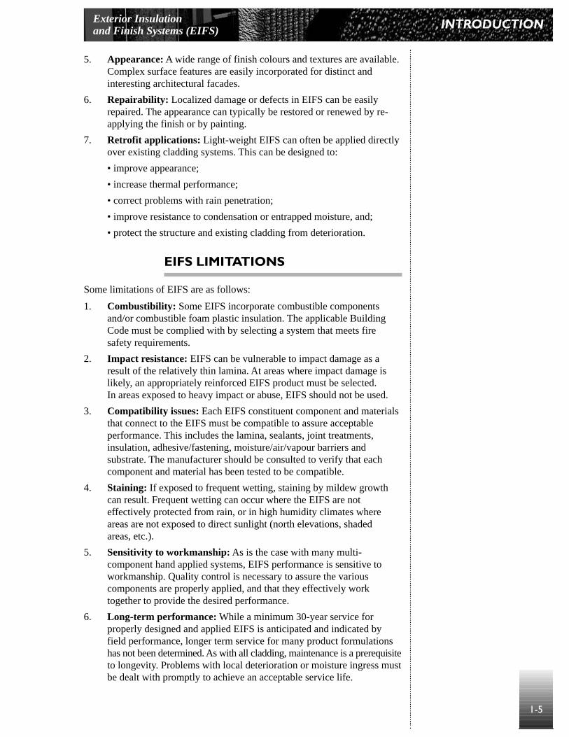
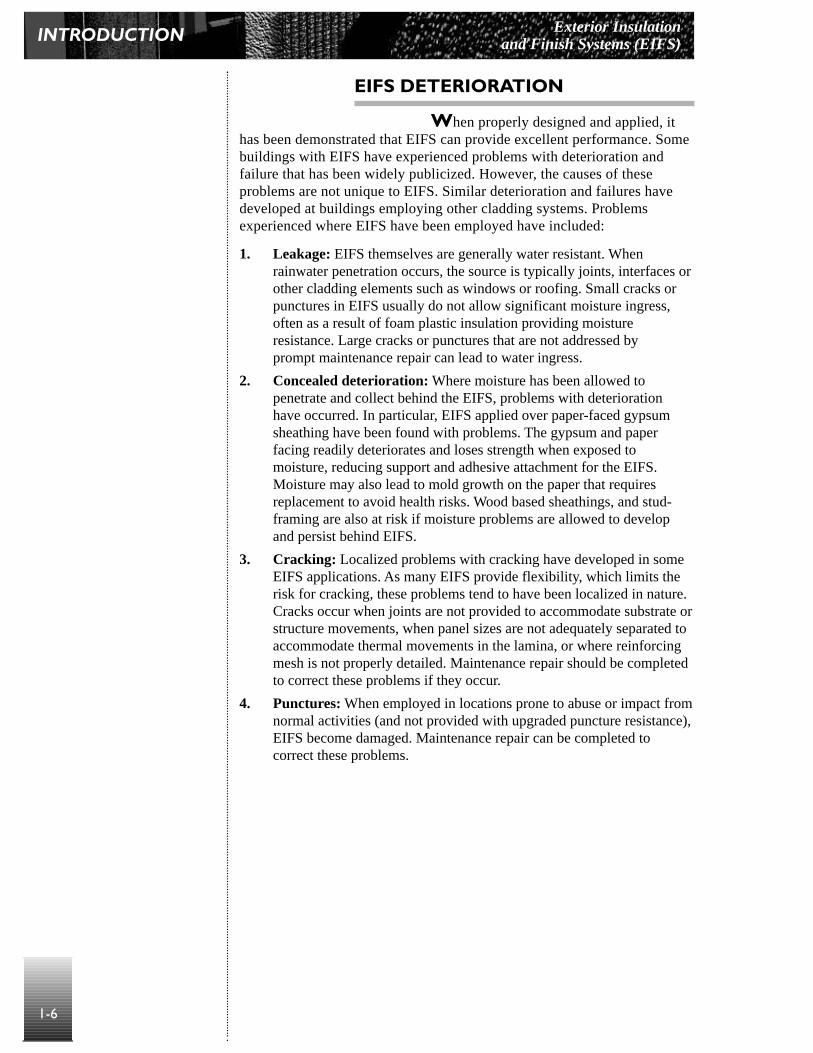


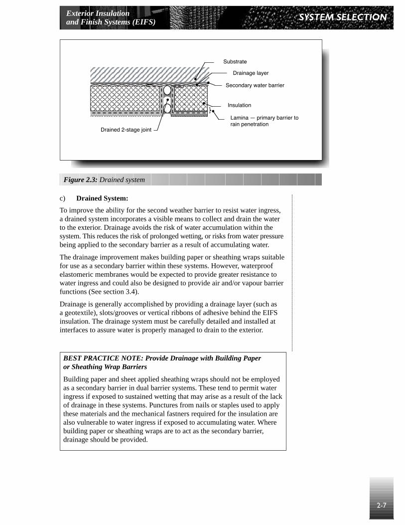


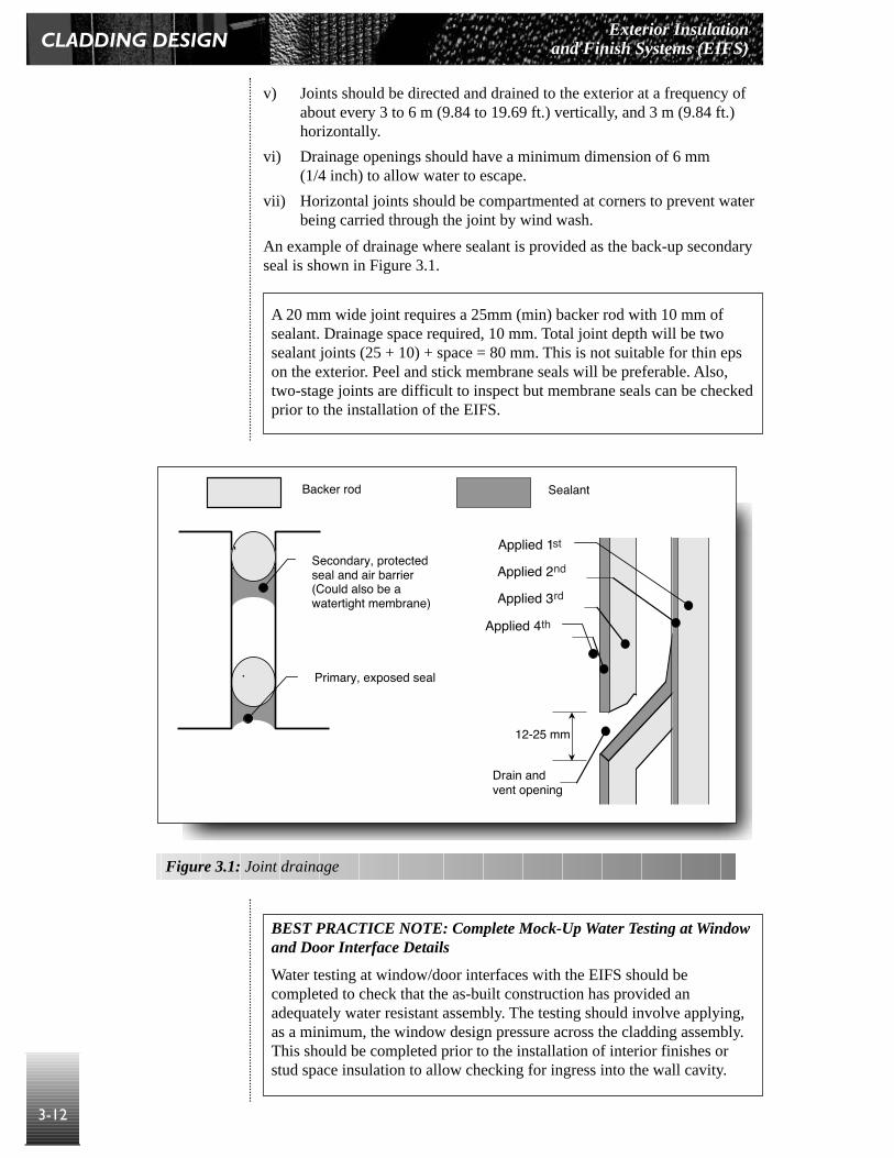
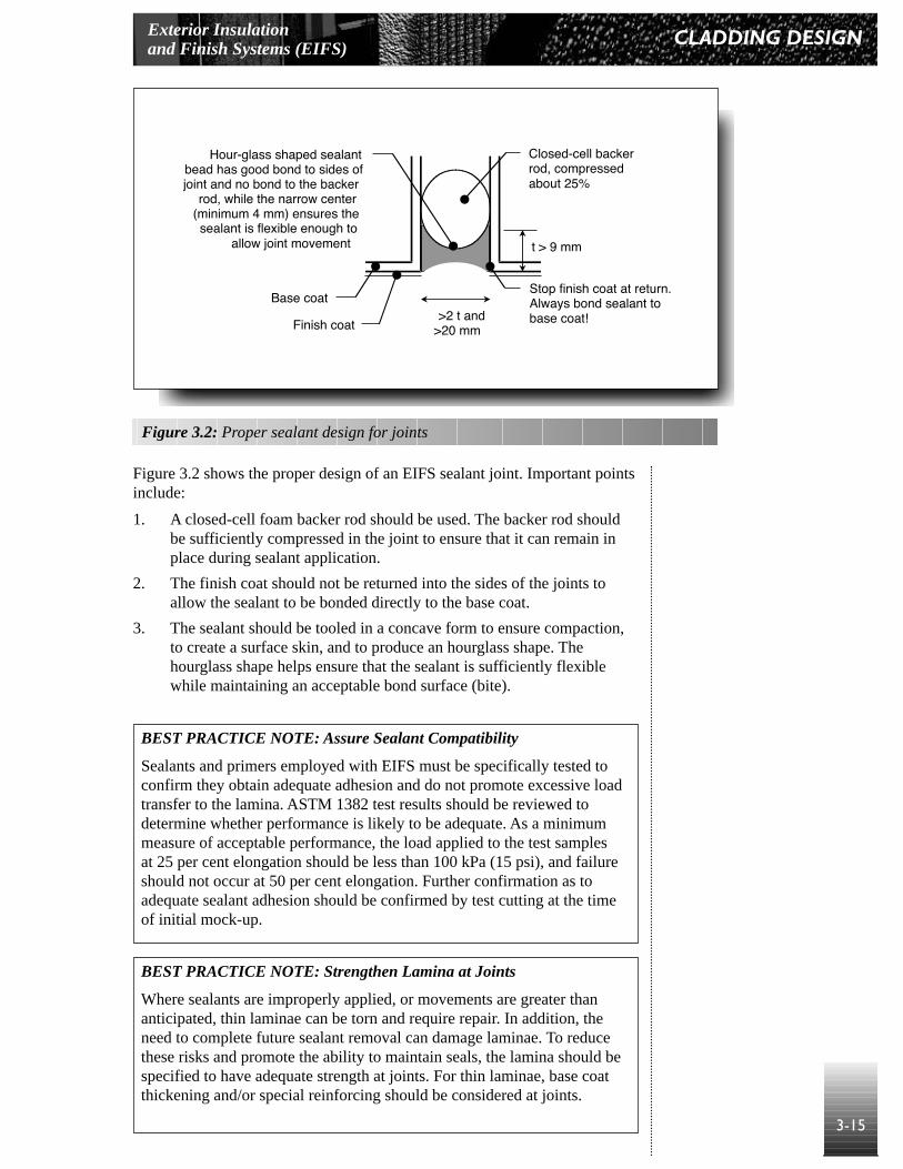


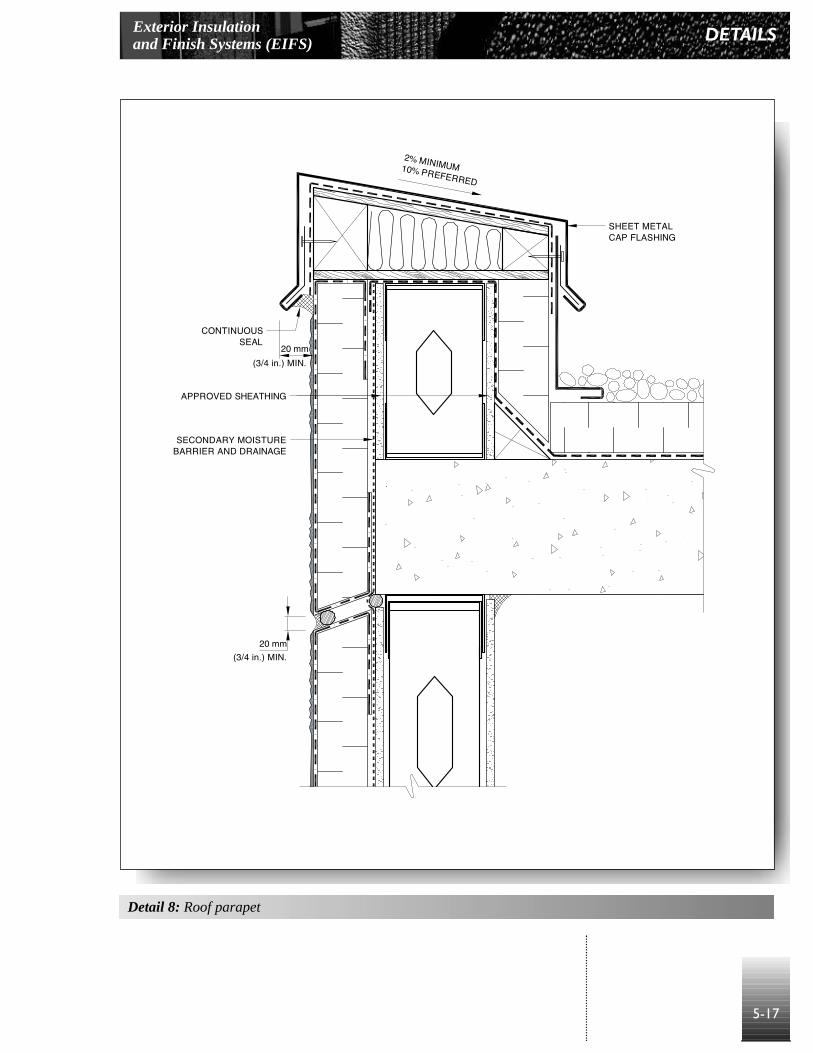


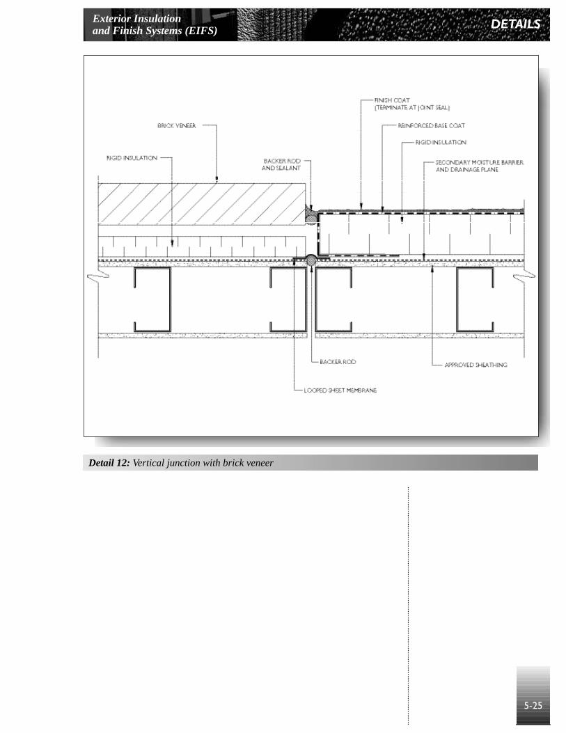


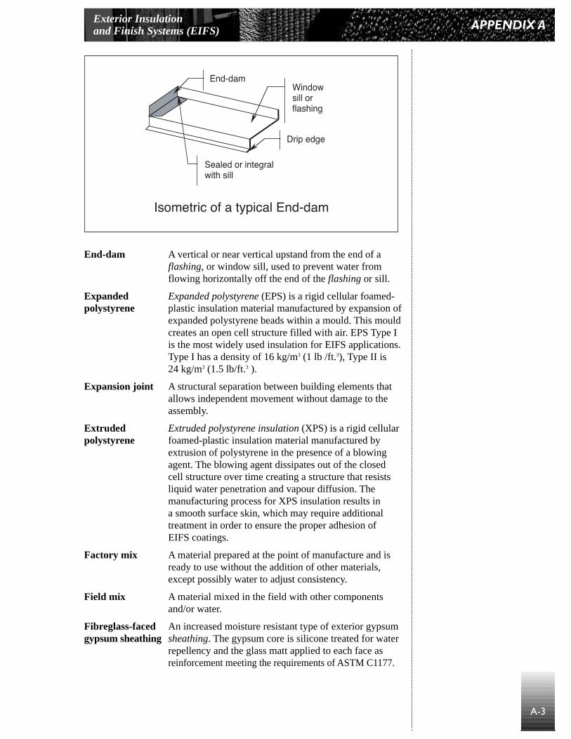


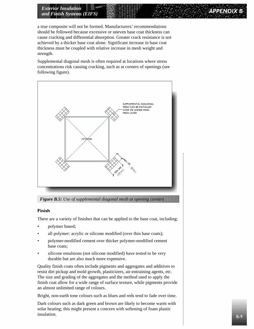

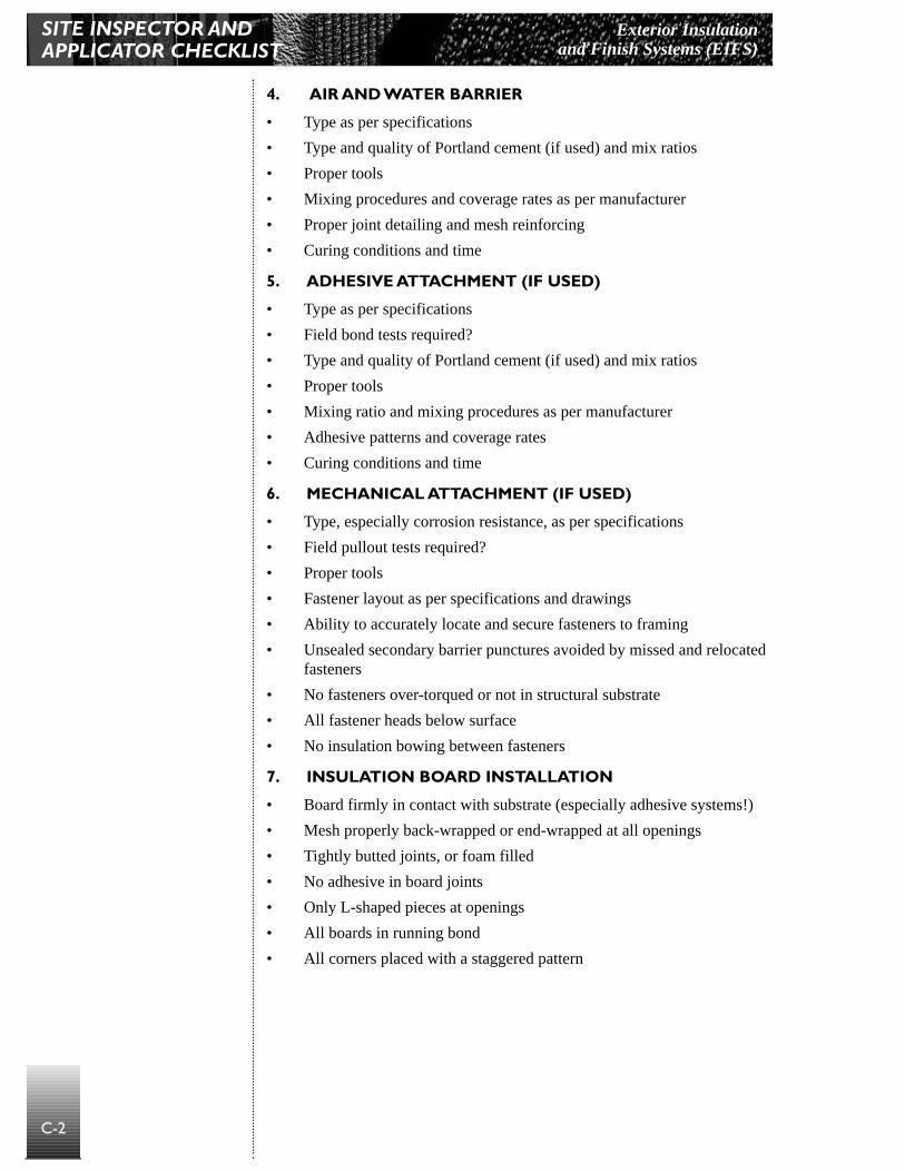


![Building a Chat App in JavaScript Best Practice Guide · Building a Chat App in JavaScript Best Practice Guide ... 'lil-bab' ] Binding extra information (“State”) for each user](https://static.documents.pub/doc/80x56/5ceadf3b88c993886b8bad07/building-a-chat-app-in-javascript-best-practice-guide-building-a-chat-app-in.jpg)


