Best Practice in Adhesive-Bonded Structures and Repairs April 2007 DOT/FAA/AR-TN06/57 This document is available to the public through the National Technical Information Services (NTIS), Springfield, Virginia 22161 U.S. Department of Transportation Federal Aviation Administration o te technical note technic a
Transcript
Best Practice in Adhesive-Bonded Structures and Repairs April 2007 DOT/FAA/AR-TN06/57 This document is available to the public through the National Technical Information Services (NTIS), Springfield, Virginia 22161
U.S. Department of Transportation Federal Aviation Administration
ote
tech
nica
l not
e te
chni
ca
NOTICE
This document is disseminated under the sponsorship of the U.S. Department of Transportation in the interest of information exchange. The United States Government assumes no liability for the contents or use thereof. The United States Government does not endorse products or manufacturers. Trade or manufacturer's names appear herein solely because they are considered essential to the objective of this report. This document does not constitute FAA certification policy. Consult your local FAA aircraft certification office as to its use. This report is available at the Federal Aviation Administration William J. Hughes Technical Center’s Full-Text Technical Reports page: actlibrary.tc.faa.gov in Adobe Acrobat portable document format (PDF).
2. Government Accession No. 3. Recipient's Catalog No.
4. Title and Subtitle BEST PRACTICE IN ADHESIVE-BONDED STRUCTURES AND REPAIRS
5. Report Date April 2007
6. Performing Organization Code
7. Author(s) Max Davis and John Tomblin
8. Performing Organization Report No.
9. Performing Organization Name and Address National Institute for Aviation Research Wichita State University Wichita, KS 67260-0093
10. Work Unit No. (TRAIS)
11. Contract or Grant No.
12. Sponsoring Agency Name and Address U.S. Department of Transportation Federal Aviation Administration Air Traffic Organization Operations Planning Office of Aviation Research and Development Washington, DC 20591
13. Type of Report and Period Covered Technical Note
14. Sponsoring Agency Code AIR-100
15. Supplementary Notes The Federal Aviation Administration Airport and Aircraft Safety R&D Division Technical Monitor was Curtis Davies. 16. Abstract The opinions expressed in this technical note were presented at the Federal Aviation Administration (FAA) Bonded Structures workshop in 2004. The FAA, realizing their value, commissioned a written record of these observations and recommendations. These observations and recommendations represent the experiences, some anecdotal, in the application and maintenance of bonded structures on one group. This document does not represent a comprehensive survey and analysis of the failures or best corrective actions for bonded structures, but data that resulted from real-world applications and experience with disbands and other adhesive failures in structural applications. 17. Key Words Adhesive bonding, Bonded repair, Surface preparation
18. Distribution Statement This document is available to the public through the National Technical Information Service (NTIS) Springfield, Virginia 22161
19. Security Classif. (of this report) Unclassified
20. Security Classif. (of this page) Unclassified
21. No. of Pages 58
22. Price
Form DOT F 1700.7 (8-72) Reproduction of completed page authorized
TABLE OF CONTENTS
Page EXECUTIVE SUMMARY ix INTRODUCTION 1 Structural Adhesive Bonding Background 1 Theories of Adhesive Bonding 2 Bond Strength and Durability 4 Understanding Bond Failures 5 Identification of Adhesive Bond Failures 6 Cohesion Failures 6 Adhesion Failures 8 Sandwich Panel Failures 10 Cohesion Failures in Sandwich Panels 11 Adhesion Failures in Sandwich Panels 12 Failure of Composite Bonds 15 Failures in Bonded Repairs 16 DESIGN AND ANALYSIS 17 Average Shear Stress Design Methodology 18 Load Capacity Design Methodology 18 Overlap Length 20 Cost-Saving Test Design 21 The RAAF Design Methodology 21 Finite Element Analysis 24 Practical Considerations 24 MATERIALS AND PROCESS QUALIFICATION 28 Significant Issues 28 Selection of Surface Preparation Processes 28 Materials Selection 29 Basic Selection Criteria 29 Repair Materials Selection 31
iii
Management of Quality 32 Factors Influencing Quality 33 Contamination Control 33 Facilities 35 Materials Control 36 Assurance of Product Compliance 36 Maintenance of Usable Properties During Storage 36 Assurance of Adhesive Cure 37 Repair Heating Procedures 39 Heater Configuration 39 Temperature Sensor Configuration 40 PRODUCTION DEVELOPMENT, SUBSTANTIATION, AND SUPPORT 42 Substantiation of Structural Integrity 42 Support 45 REFERENCES 46
iv
LIST OF FIGURES Figure Page 1 Corrosion Damage Resulting From Moisture Entrapment Under a Failed Non-Load-Bearing Adhesive Bond Applied After Minimal Surface Preparation 5 2 Detailed Photographs of Adhesive Bonds That Have Failed by Cohesion: (a) Well-Formed Bond and (b) Highly Voided Bond 7 3 Fatigue Striations Occurring at the Plane of the Carrier Cloth in Adhesive FM73 8 4 Photograph of an Adhesion Failure Surface From an Elevator Trim Tab Hinge Attachment Point Showing Replicated Serial Number From Hinge Surface Which is Cast Into Adhesive 9 5 Photograph of a Mixed Failure Mode 10 6 Adhesive Bond Failure Modes for Honeycomb Sandwich Panels 10 7 Flatwise Tension Failure of Sandwich Panel due to Internal Pressure Occurring During Repair Heating Cycle 11 8 Strong Node Bond Failure in Honeycomb Sandwich Panel Caused by Internal Pressure During Repair and X-Ray Image of a Strong Node Bond Failure 12 9 Skin-to-Adhesive Cohesion Failure in a Sandwich Panel 13 10 Photographs of Core and Adhesive Surfaces After Adhesion Filet Bond Failure 13 11 Photograph of Disbonded Sandwich Panel Showing Matching Surface of the Sandwich Panel Skin 14 12 Weak Node Bond Failure in a Honeycomb Sandwich Panel and X-Radiograph of Honeycomb Sandwich Panel Showing Weak Node Bond Failures 14 13 Composite-Bonded Patch Failure Showing Interfacial Failure Between Adhesive and Patch Surface due to Presence of a Silicone Release Agent on Peel Ply 15 14 Photograph of Patch That Suffered Adhesion Failure in Service 17 15 Variables Used in Analysis 19 16 Idealized Elastic-Plastic Shear Stress Distribution in Bonded Joint 20
v
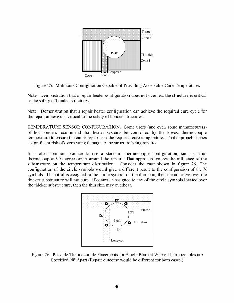
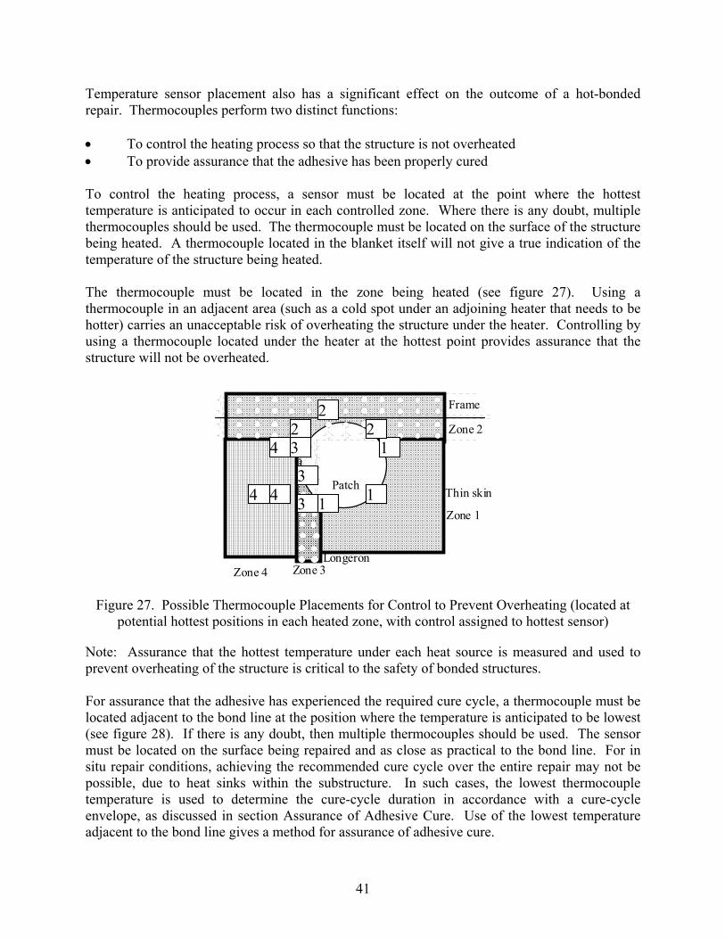
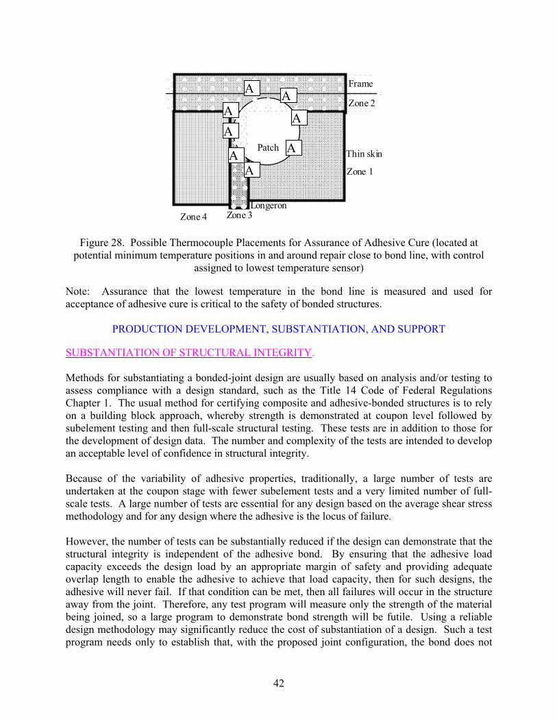
17 Corrosion Damage in Sandwich Panel Caused by Moisture Entry Through Fasteners Used Because of Lack of Confidence in Adhesive Bonding 25 18 Photograph of Failed Injection Repair Showing Replicated Impression of Surface That Disbonded Prior to Injection Repair 26 19 Surface of Production Void on F-111 Rudder and Injected Adhesive That Failed to Bond to Slick Surface Created by Void 27 20 Corrosion Damage due to Previous Injection Repair in Honeycomb Sandwich Panel 27 21 Macrovoiding in Adhesive Bond due to High Moisture Content 34 22 Microvoiding in Moisture-Contaminated Adhesive Cured Under Vacuum 34 23 Cure-Cycle Envelope for a Typical Film Adhesive System 38 24 Example of Single Heat Source Configuration Showing Problem Repair and Typical Single Blanket 39 25 Multizone Configuration Capable of Providing Acceptable Cure Temperatures 40 26 Possible Thermocouple Placements for Single Blanket Where Thermocouples
are Specified 90º Apart 40 27 Possible Thermocouple Placements for Control to Prevent Overheating 41 28 Possible Thermocouple Placements for Assurance of Adhesive Cure 42
vi
LIST OF TABLES Table Page 1 The RAAF Certification Requirements for Possible Conditions on Bonded Repairs
Based on a Comparison of Bond-Load Capacity With Design-Load Cases 23 2 Plastic Zone Sizes for Various Joint Conditions 23
vii
LIST OF ACRONYMS
AVF Adhesive variability factor DSC Differential scanning calorimetry DUL Design ultimate load FAA Federal Aviation Administration FEA Finite element analysis FEM Finite element method NDI Nondestructive inspection NDT Nondestructive testing r.h. Relative humidity RAAF Royal Australian Air Force TTCP Technical Cooperation Program Tg Glass transition temperature
viii
EXECUTIVE SUMMARY The opinions expressed in this technical note were presented at the Federal Aviation Administration (FAA) Bonded Structures Workshop in 2004. The FAA, realizing their value, commissioned a written record of these observations and recommendations. These observations and recommendations represent the experiences, some anecdotal, in the application and maintenance of bonded structures for one group. This document does not represent a comprehensive survey and analysis of the failures nor best corrective actions for bonded structures, but data that resulted from real-world applications and experience with disbonds and other adhesive failures in structural applications. This professional assessment of important factors in adhesive-bonding technology is based on the author’s personal experience of more than 32 years with adhesive-bonded structures and development of adhesive-bonded repair technology. Initial research activities were directed at the Australian crack-patching technology that relied upon adhesively bonded composite patches to arrest or inhibit crack growth in metallic structures. The bonding technology was then adapted for bonded repairs to sandwich structures, principally on F-111 aircraft. That application led to a reduction of the repeat-repair rate from over 42 percent in 1992 to only two known bonded-repair failures since that date. During that time, the author also developed skills in forensic assessment of adhesive-bond failures, leading to an understanding of the relationship between process deficiencies and service defects.
ix/x
INTRODUCTION
Many of the insights presented in this technical note on adhesive bonding are the result of dialog between various international regulators and defense customers of aviation applications for this manufacturing and repair process. These insights were coordinated by The Technical Cooperation Program (TTCP) that has shared various design and continued airworthiness issues of products using bonded structures. The TTCP, headed by the late John W. (Jack) Lincoln produced a preliminary treatise on the subject, Certification of Bonded Structures, prepared by Action Group 13 of the TTCP. The Federal Aviation Administration (FAA) has initiated further work to establish certification requirements for adhesively bonded structure. The opinions expressed in this technical note were presented at the FAA Bonded Structures Workshop in 2004. The FAA, realizing their value, commissioned a written record of these observations and recommendations. These observations and recommendations represent the experiences, some anecdotal, in the application and maintenance of bonded structures for one group. This document does not represent a comprehensive survey and analysis of the failures nor best corrective actions for bonded structures, but data that resulted from real-world applications and experience with disbonds and other adhesive failures in structural applications. STRUCTURAL ADHESIVE BONDING BACKGROUND. Adhesive bonding of structures has significant advantages over conventional fastening systems. Bonded joints are considerably more fatigue resistant than mechanically fastened structures [1] because of the absence of stress concentrations that occur at fasteners. Joints may be lighter due to the absence of fastener hardware. A major advantage of adhesive bonds, which is often not understood, is that adhesive bonds may be designed and made in such a way that they can be stronger than the ultimate strength of many metals in common use for aircraft construction. In other words, the adhesive will never be the locus of failure for metal-to-metal bonds, provided that the processing is adequate to provide long-term environmental durability. Because of stress concentration effects, mechanically fastened structures will always fracture at the fasteners at a load well below the material ultimate strength. The disadvantages of an adhesive-bonded joint include the fact that it is a single fastener, and hence, there is no redundancy of load paths unless alternative load paths are added. (Fasteners in an adhesive bond introduce their own problems, which will be discussed in the section on Practical Considerations.) Adhesive bonding is a sensitive process, and therefore, technicians must have appropriate levels of proficiency to perform the bonding process. A significant limitation of adhesive bonding is that there is no method for providing absolute assurance of bond integrity. All existing quality control tests and nondestructive testing (NDT) inspections satisfy conditions that are necessary for bond integrity, but no test or combination of tests provides assurance of a sufficient condition to guarantee bond integrity. Integrity can only be implied on the basis of quality management and associated quality assurance tests on critical process steps. Adhesive bonding may also be used for repairs to metallic structures and offers even further advantages over mechanically fastened repairs [2]. First, the adhesive bond is considerably more
1
efficient in load transfer at the edge of a defect such as a crack. Second, repair to a cracked structure involves an upper bound on stress intensity that is equivalent to the opening displacement of a bonded butt joint. Consequently, the stress intensity after repair of a cracked structure is lower, by an order of magnitude, than for a mechanically fastened repair, to the extent that removal of pre-existing cracks is not a recommended practice. Adhesive-bonded repairs are also easier to inspect for underlying damage due to the absence of edge effects caused by fasteners. Eddy-current methods are capable of detecting cracks under bonded repairs. Bonding seals an area against moisture ingress (provided that the surface preparation is capable of producing a durable bond) so that the chance of corrosion is reduced. One further advantage of an adhesive bond is that if the bonding process fails, it is possible to remove the repair. This leaves the structure in its original condition, unlike a mechanically fastened repair where the structure will have many new fastener holes. Adhesive bonding of composite joints presents a method for the manufacture of efficient, lightweight joints. Adhesive bonds may also be co-bonded to reduce production times. A significant difference between bonded joints in metallic and composite structures is that it is possible to design a joint between metals so that the adhesive is always stronger than the metal being joined. This is not always possible with composites because of the significantly higher strength of composite materials. Another difference is the first-ply peel failure mode of composites where the relatively low inter-laminar shear or peel strength of the resin system causes failure of the composite before failure of the bond occurs. THEORIES OF ADHESIVE BONDING. To understand the causes of adhesive bond failures, it is first necessary to understand how adhesive bonds function. Then, the importance of and sequence of preparation processes prior to adhesive bonding becomes apparent. The four basic theories of adhesive bonding are as follows [3]: • The mechanical interlock theory, which attributes adhesive bond strength to surface
roughness. • The diffusion model, which attributes adhesive bond strength to the diffusion of
molecules at the interface of the adhesive at the bonding surface. • The electrostatic attractive model, which attributes adhesive bond strength to weak
molecular attraction. • The adsorption theory, which attributes adhesive bond strength to a combination of weak
molecular attraction and chemical bonds (ionic, covalent, and metallic) between the adhesive and the surface of the adherends.
While surface roughness has been shown to be a factor in adhesion [4], the mechanism of adhesion is not just a mechanical interlock. The adsorption theory is most widely accepted as representing the actual behavior of adhesive bonds. Chemical reactions associated with the adsorption theory can be used to provide a mechanistic explanation for short-term bond strength
2
while also explaining the gradual degradation of these bonds by hydration of the interface [5]. According to the adsorption theory of adhesion, adhesive bonds depend upon the formation of chemical bonds between the adhesive and the surface of the adherends at the interface. These chemical bonds may be ionic, covalent, metallic, or electrostatic attractive. This theory explains why adhesive bonds on poorly prepared surfaces initially demonstrate high bond strength but have poor service durability. The surface preparation process used during manufacture, therefore, determines the strength of the interface. If it is accepted that adhesion is related to chemical reactions, then one understands that the surface must be free of contaminants that would hinder the formation of chemical bonds. One also understands that the surface must be chemically active to enable the reactions to occur. Since solvent wiping alone does not change the chemical reactivity of most surfaces, then solvent cleaning alone is not sufficient to enable development of an adhesive bond. Hence, some process is required to produce a chemically active surface. Such a process may involve abrasion or chemical etching to remove the chemically stable surface from the adherends. However, even if a surface is clean and chemically active, these conditions alone are not sufficient to ensure long-term bond integrity. Many bonds formed on surfaces thought to be clean, chemically active have failed in later service, usually due to hydration of an oxide layer as the interface is attacked by water. A classic example of this mechanism occurs on the surface of bonds to aluminum. If the surface is solvent degreased and abraded prior to bonding, adequate strength is demonstrated if the joint is tested soon after manufacture. If, however, the joint is allowed to stand, then the strength of the joint will degrade with time. The explanation for this phenomenon is that the chemical bonds formed during adhesive cure are disrupted as the aluminum oxide layer hydrates. Consequently, as the oxide hydrates, the interface weakens, leading to a loss in bond strength. If allowed to proceed to completion, these chemical reactions will eventually result in total loss of bond strength. Such surfaces exhibit fully interfacial (adhesion) failure with all adhesive left on one surface and none on the other. Thus, it may be concluded that an essential feature of any surface preparation process is that it must produce a surface that is resistant to hydration. Hence, three conditions are necessary for proper surface preparation for adhesive bonding: • The surface must be free of contamination. • The surface must be chemically active. • The surface must be resistant to hydration. These conclusions also influence the sequence of processing. A surface must be degreased prior to chemical or abrasion treatment to produce a chemically active surface. If the surface is degreased after exposing the active surface, the cleaning process will spread any contamination over the entire surface. It has been shown [4] that solvent degreasing of a surface will result in a mono-layer of solvent residue that can inhibit chemical reaction. Similarly, if the surface is not cleaned prior to treatment to produce a chemically active surface, contamination will either prevent intimate contact with the etchant or will be spread by abrasion. Since the chemical activity of a surface degrades with time, the need to minimize surface exposure time after treatment is obvious.
3
BOND STRENGTH AND DURABILITY. One of the major contributing factors to poorly performing adhesive bonds is the failure of many production organizations and regulators to differentiate between bond strength and bond durability. In the past, some bonding shops relied on the lap-shear strength test, ASTM D 1002, as a quality assurance test for bonding processes. Some researchers [6] have even used this test for selection of surface preparation for bonding processes. Strength and fatigue tests may show that the bond strength is adequate or the structure is sound and has sufficient fatigue resistance at the time of testing, but they do not verify that the component will be durable throughout its service life. Bond durability is dependent on the resistance of the adhesive-to-adherend interface to attack by water. Water causes hydration of the surface layer atoms and in the process breaks the chemical bonds between the adhesive and the substrate, thus leading to an interfacial failure of the bond. The surface preparation process performed at the time the components are bonded together establishes the resistance to hydration. Three possible outcomes after fabrication of an adhesive bond, depending on the integrity of the process used and the integrity of the implementation of that process, are as follows: • A badly prepared or contaminated surface will not be chemically active, will have poor
short-term strength, and will exhibit exceptionally poor durability. These problems can be identified by lap-shear tests performed as a quality control measure.
• A poorly prepared surface may be chemically active and form a high number of chemical bonds, which give good short-term strength, but if the surface is not resistant to hydration, the bond strength will gradually deteriorate to zero. This is typical of a poorly validated process that is performed well. Unfortunately, this standard of bond usually passes any short-term quality control tests and even fatigue tests.
• A well-prepared surface will be chemically active, and a high number of chemical bonds
are formed with the adhesive, but more importantly, these bonds will be resistant to hydration. Such bonds will maintain a high strength for a long period of service and will also pass all quality control and fatigue tests.
The difficulty in acceptance of bonded structures is, therefore, the inability to differentiate between a poorly selected surface treatment that has been prepared well and a surface prepared with a validated, reliable surface preparation that has also been performed well. In the past, regulators [7] have relied on static strength and fatigue testing to demonstrate airworthiness. Unfortunately, these tests will not interrogate the environmental durability of an adhesive bond. Therefore, it is possible that bonded structures that meet current certification requirements may later fail in service due to degradation caused by unreliable surface preparation processes used during manufacturing. Because surface preparation is critical to the durability of an adhesive bond and because degraded adhesive bonds may exhibit negligible strength, surface preparation must be considered as a critical element in any certification program for flight structures.
4
The fact that bond degradation is unrelated to loads has been demonstrated by failures of bonded sandwich panels experienced by the Royal Australian Air Force (RAAF). Spare bonded panels removed from storage have failed even before the components were fitted to an aircraft. A fallacy that adhesive bonds fail because of loads leads to the thought that structures that experience only low loads do not need extensive surface preparation. A substantial number of examples exist where this philosophy has led to the total failure of the bond. In figure 1, adhesive filler had been added to a panel to dampen vibrations. Because the filler would not be expected to carry loads, only a simple surface preparation was used during manufacture. The subsequent disbond of the insert material led to water entrapment and severe corrosion of the underlying metal.
Figure 1. Corrosion Damage Resulting From Moisture Entrapment Under a Failed Non-Load-Bearing Adhesive Bond Applied After Minimal Surface Preparation
Note: Demonstration of the resistance of the interface to environmental degradation (hydration) produced by the surface preparation processes is critical to the safety of bonded structures. UNDERSTANDING BOND FAILURES. Best practice in development and substantiation of adhesive-bonded structures requires a basic understanding of failure modes for an adhesive bond. Adhesive-bonded aircraft structures have been in service for a considerable period of time due to their lightweight and superior fatigue performance over mechanically fastened structures. However, bonded structures and joints have demonstrated considerable variation in the reliability of service performance. Disbonds in joints and sandwich panels have been, at times, incorrectly attributed to a wide range of causes, including fatigue [8]. Often, the type of adhesive was changed in an attempt to improve the performance of bonded components, and in all but a few cases, the end result was further bond failure. Failure to recognize the real causes of bond failures has allowed continued use of deficient bonding processes, both in the continued manufacture of defective components and the use of
5
poor repair technology [9]. Further, the lack of appreciation of bond failure mechanisms has meant that inappropriate test methods continue to be used for selection of bonding materials and processes. Examples of bond failures that characterize the results of inappropriate bonding practices are shown in the Identification of Adhesive Bond Failures section. These are based on extensive service experiences with bonded panels and repairs. The objective is to establish better bonding practices by identification of the real causes of adhesive bond failure and to dispel the many reasons for bond failures, which are frequently espoused to operators by regulators, bonded-structure fabricators, and repair stations. Clear identification of the failure mode plays an important role in determining the causes of bond failure. Note: Correct and reliable identification of the causes of adhesive bond failures is critical to the safety of bonded structures. IDENTIFICATION OF ADHESIVE BOND FAILURES. An adhesive-bonded joint may fail in three basic ways: • Within one of the adherends that is outside the joint (this is a desirable outcome because
the adhesive joint has achieved the maximum possible performance). • Through the adhesive layer (cohesion1 failure) when the strength of the adhesive bond is
exceeded. • At the interface between the adhesive and one of the adherends (adhesion failure), usually
at a load well below the design strength of the bond. Failure of the adherends outside the joint is achievable [10] for well-designed and fabricated adhesive bonds in moderately thin adherend materials. This condition is highly desirable because it may reduce the testing required for structural certification [11]. If the adhesive has a load capacity that is higher than the strength of the surrounding structure, then only the surrounding structure needs to be tested to demonstrate structural integrity. Such bonds are also damage tolerant and can be designed using simple design procedures [11]. Because the other forms of bond failure (cohesion and adhesion) are related to failures of the bond, discussion will focus on these failure modes. COHESION FAILURES. Cohesion bond failures result in fracture of the adhesive and are characterized by the clear presence of adhesive material on the matching faces of both adherends. Failure usually occurs by shear, but peel stresses or a combination of shear and peel may also cause a cohesion failure. This type of failure typically occurs in lap-shear tests such as ASTM D 1002 or peel tests such as ASTM D 1781-76. In cohesion failures, the adhesive surface typically appears rough (see figure 2) and may have a lighter color than the bulk adhesive material. In film adhesive systems, failure usually occurs along the plane of the carrier cloth (a material added during the production of the adhesive roll to aid handling during use). Cohesion
1 Common practice is to designate interfacial failure of a bond in the adjectival form “adhesive” to describe interfacial failure. This risks
confusion with failure of the adhesive material, which is termed “cohesive” failure. In order to more clearly distinguish the forms of failure, the author advocates the use of the words “adhesion” and “cohesion.”
6
failures found in service are typically caused by poor joint design (insufficient overlap length or excessive peel), although excessive porosity will also result in cohesion failure (see figure 2). The high void content shown resulted from exposure of the precured adhesive film to high humidity).
(a) (b)
Figure 2. Detailed Photographs of Adhesive Bonds That Have Failed by Cohension (Well-formed bond (a) shows some light coloration. The highly voided bond (b) exhibits
cohesion. Failure only in the regions where adhesive was present. Pattern is due to carrier cloth with approximately 0.5-mm pitch.)
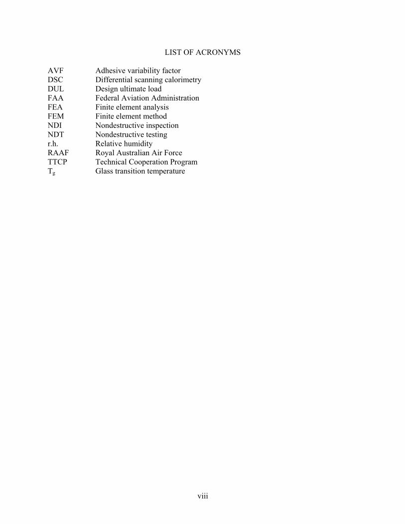
Adhesive bonds are very fatigue resistant [10] and only under certain circumstances will a cohesion failure be caused by fatigue. The PABST program [12] showed that fatigue of the bond should never occur on thin materials, such as those typically used for aircraft skins, provided that the joint has sufficient overlap length. The perception that adhesive bonds usually fail by fatigue has been perpetuated by old FAA training publications [8]. Fatigue failures in adhesive bonds usually only occur where the structure being joined is quite thick and loads are sufficiently high. Fatigue failures always occur through the adhesive in a cohesion failure. Fatigue failures typically do not occur at the interface; however, interfacial fatigue failures that do occur are symptomatic of a degraded interface. For film adhesives, fatigue failures usually propagate through the plane of the carrier cloth. Fatigue failures have occurred in the adhesive used to bond boron reinforcements to RAAF F-111 upper-wing pivot fittings. Careful examination under a high-power microscope can detect localized fatigue striations within the failure surface (see figure 3).
7
Figure 3. Fatigue Striations Occurring at the Plane of the Carrier Cloth in Adhesive FM73 (Pattern is due to carrier cloth with approximately 0.5-mm pitch.)
ADHESION FAILURES. Adhesion failures can be caused in three ways: • Ineffective generation of a chemically active surface due to contamination of the bonding
surfaces or ineffective performance of a surface preparation process during production. • Inability of the surface preparation to produce a chemically active surface that is resistant
to hydration due to inappropriate process selection and validation. • Adhesive curing before the bond was formed.
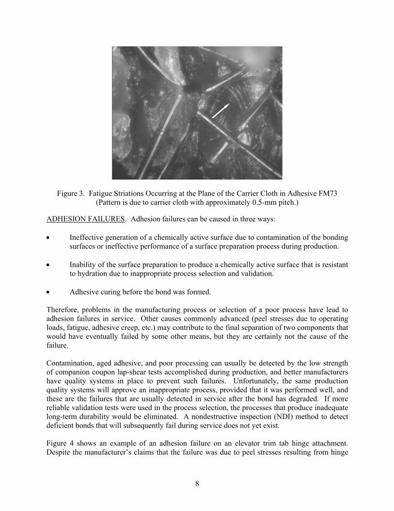
Therefore, problems in the manufacturing process or selection of a poor process have lead to adhesion failures in service. Other causes commonly advanced (peel stresses due to operating loads, fatigue, adhesive creep, etc.) may contribute to the final separation of two components that would have eventually failed by some other means, but they are certainly not the cause of the failure. Contamination, aged adhesive, and poor processing can usually be detected by the low strength of companion coupon lap-shear tests accomplished during production, and better manufacturers have quality systems in place to prevent such failures. Unfortunately, the same production quality systems will approve an inappropriate process, provided that it was performed well, and these are the failures that are usually detected in service after the bond has degraded. If more reliable validation tests were used in the process selection, the processes that produce inadequate long-term durability would be eliminated. A nondestructive inspection (NDI) method to detect deficient bonds that will subsequently fail during service does not yet exist. Figure 4 shows an example of an adhesion failure on an elevator trim tab hinge attachment. Despite the manufacturer’s claims that the failure was due to peel stresses resulting from hinge
8
actuating loads, the absence of a significant fracture of the adhesive together with the clear replication of the hinge serial number confirms that this is an interfacial failure due to the original manufacturing process.
Disbond from
Hinge Serial
Number
Figure 4. Photograph of an Adhesion Failure Surface From an Elevator Trim Tab Hinge Attachment Point Showing Replicated Serial Number From Hinge Surface Which is Cast Into Adhesive (Photograph courtesy of Steve Emery, Civil Aviation Safety Authority, Canberra.)
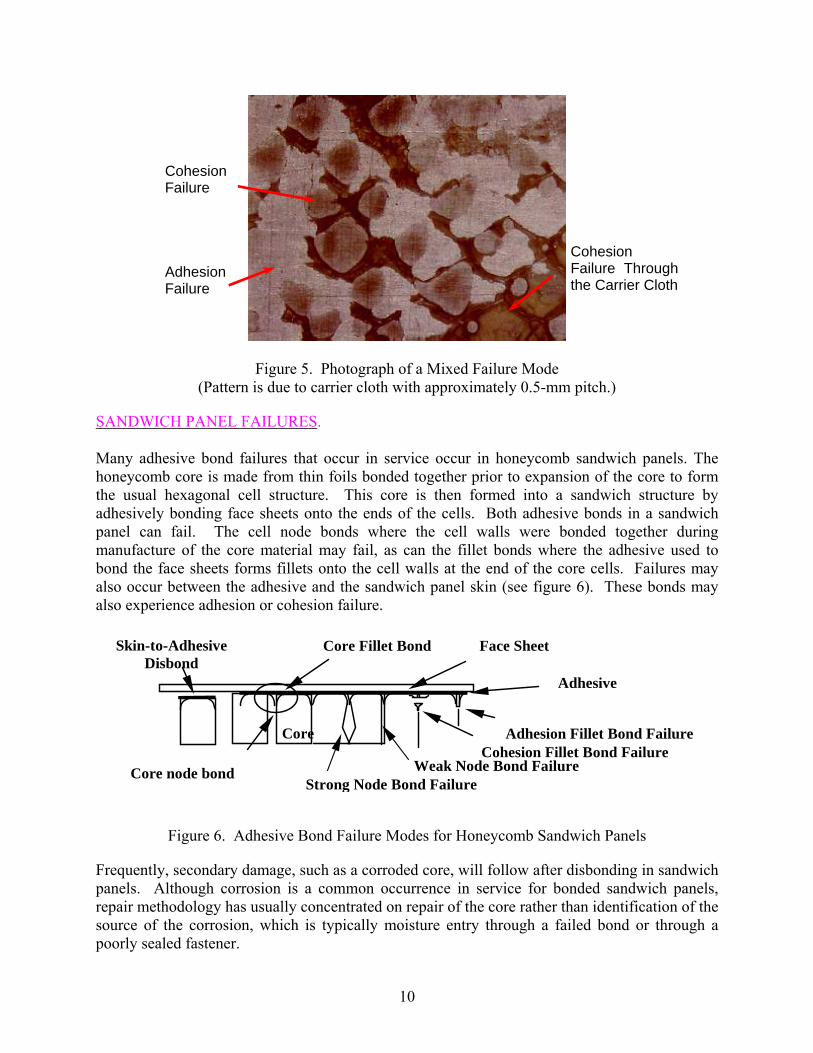
Care is required to correctly assess surfaces that show mixed adhesion and cohesion failure. Interfacial degradation occurs over a period of time, and if over this time a partially degraded bond is subjected to a high load, then the weakened interface may fail thus overloading the adhesive in the regions that have not fully degraded. This will give the appearance of a mixed mode failure (see figure 5) where the adhesion failure regions exhibit an absence of adhesive while the cohesion failure regions exhibit some adhesive fracture. If the surface shows some adhesion failure and the adhesive has fractured close to the surface (and not in the carrier cloth) on the cohesion failure regions, then the failure is an adhesion failure which occurred before the interface could fully degrade. True cohesion failures always occur in the plane of the adhesive carrier cloth.
9
Adhesion Failure
Cohesion Failure
Cohesion Failure Through the Carrier Cloth
Figure 5. Photograph of a Mixed Failure Mode
(Pattern is due to carrier cloth with approximately 0.5-mm pitch.)
SANDWICH PANEL FAILURES. Many adhesive bond failures that occur in service occur in honeycomb sandwich panels. The honeycomb core is made from thin foils bonded together prior to expansion of the core to form the usual hexagonal cell structure. This core is then formed into a sandwich structure by adhesively bonding face sheets onto the ends of the cells. Both adhesive bonds in a sandwich panel can fail. The cell node bonds where the cell walls were bonded together during manufacture of the core material may fail, as can the fillet bonds where the adhesive used to bond the face sheets forms fillets onto the cell walls at the end of the core cells. Failures may also occur between the adhesive and the sandwich panel skin (see figure 6). These bonds may also experience adhesion or cohesion failure.
Adhesion Fillet Bond Failure
Face Sheet
Core
Core Fillet BondSkin-to-Adhesive Disbond
Core node bond Cohesion Fillet Bond Failure
Adhesive
Strong Node Bond FailureWeak Node Bond Failure
Figure 6. Adhesive Bond Failure Modes for Honeycomb Sandwich Panels
Frequently, secondary damage, such as a corroded core, will follow after disbonding in sandwich panels. Although corrosion is a common occurrence in service for bonded sandwich panels, repair methodology has usually concentrated on repair of the core rather than identification of the source of the corrosion, which is typically moisture entry through a failed bond or through a poorly sealed fastener.
10
COHESION FAILURES IN SANDWICH PANELS. Cohesion failures in sandwich panels may occur in the fillet bonds between the adhesive and the core or in the node bonds between the cell walls. Most cohesion failures in sandwich panels are caused by internal pressure during heating cycles associated with bonded repairs. The pressure is caused by entrapped moisture that vaporizes as the component is heated. When the internal pressure exceeds the flatwise tensile strength of the fillet bond (where the adhesive has wet onto the core cell walls), failure occurs [13] (see figure 7). Cohesion failure of sandwich panels may occasionally be caused by impact damage but only at energy levels sufficient to cause crushing of the core, and the failure occurs by fracture of the fillet bonds. For skins greater than six plies, cohesion failure due to impact usually occurs in composite structures with delamination damage [14], and delamination damage is far more significant to structural integrity than any disbond. Fatigue is not likely to cause cohesion failures in sandwich panels because the adhesive shear strength is substantially higher than the shear strength of the core materials.
Core Cell Wall Fracture
Cohesion Fillet Bond Failure
Figure 7. Flatwise Tension Failure of Sandwich Panel Due to Internal Pressure Occurring
During Repair Heating Cycle (Cohesion Failure of Fillet Bonds and Core Cell-Wall Fracture. Pattern is due to core cells, each approximately 3.2 mm wide.)
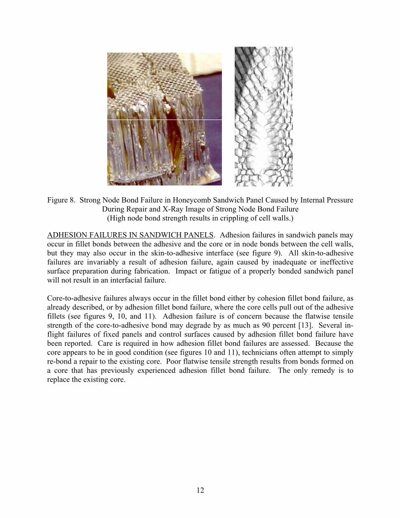
Failure of the core cell walls may occur occasionally in sandwich panels that are fabricated from lightweight core (see figure 8). This usually results from internal pressures generated by heating panels that contain moisture. If the failure is a cohesion failure of the cell wall node bond adhesive, the cell walls are usually significantly distorted. This form of failure (designated here as a strong node bond failure) is easily identified from X-ray inspections because of the clear image of the distorted cell walls. This failure mode should be compared to the weak node bond failure detailed in the next section.
11
Figure 8. Strong Node Bond Failure in Honeycomb Sandwich Panel Caused by Internal Pressure During Repair and X-Ray Image of Strong Node Bond Failure
(High node bond strength results in crippling of cell walls.)
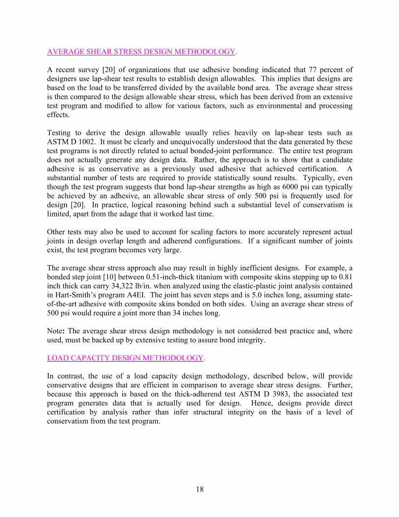
ADHESION FAILURES IN SANDWICH PANELS. Adhesion failures in sandwich panels may occur in fillet bonds between the adhesive and the core or in node bonds between the cell walls, but they may also occur in the skin-to-adhesive interface (see figure 9). All skin-to-adhesive failures are invariably a result of adhesion failure, again caused by inadequate or ineffective surface preparation during fabrication. Impact or fatigue of a properly bonded sandwich panel will not result in an interfacial failure. Core-to-adhesive failures always occur in the fillet bond either by cohesion fillet bond failure, as already described, or by adhesion fillet bond failure, where the core cells pull out of the adhesive fillets (see figures 9, 10, and 11). Adhesion failure is of concern because the flatwise tensile strength of the core-to-adhesive bond may degrade by as much as 90 percent [13]. Several in-flight failures of fixed panels and control surfaces caused by adhesion fillet bond failure have been reported. Care is required in how adhesion fillet bond failures are assessed. Because the core appears to be in good condition (see figures 10 and 11), technicians often attempt to simply re-bond a repair to the existing core. Poor flatwise tensile strength results from bonds formed on a core that has previously experienced adhesion fillet bond failure. The only remedy is to replace the existing core.
12
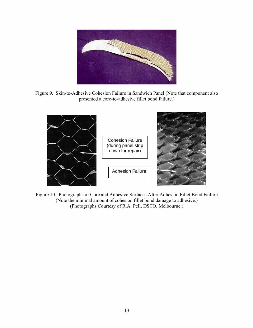
Figure 9. Skin-to-Adhesive Cohesion Failure in Sandwich Panel (Note that component also presented a core-to-adhesive fillet bond failure.)
Cohesion Failure (during panel strip down for repair)
Adhesion Failure
Figure 10. Photographs of Core and Adhesive Surfaces After Adhesion Fillet Bond Failure
(Note the minimal amount of cohesion fillet bond damage to adhesive.) (Photographs Courtesy of R.A. Pell, DSTO, Melbourne.)
13
(a) (b)
Figure 11. Photograph of Disbonded Sandwich Panel Showing Matching Surface of Sandwich Panel Skin (Note different failure modes with adhesion failure of fillet bonds leaving no trace of
adhesive on core cell walls.)
If the cell node bonds are degraded (either by plasticization of the cell wall adhesive or by degradation of the interface between the adhesive and the cell wall, which produces an adhesion failure), a weak node bond failure will occur (see figure 12). This is characterized by separation at the node bonds, but because these occur at lower internal pressures, the cell walls are barely distorted. These failures may only be detected by careful examination of X-radiographs (see figure 12).
(a) (b) Figure 12. (a) Weak Node Bond Failure in Honeycomb Sandwich Panel and (b) X-Radiograph of Honeycomb Sandwich Panel Showing Weak Node Bond Failures (Note that comparatively
FAILURE OF COMPOSITE BONDS. Adhesive bonds to composite materials may fail in the same manner as adhesive bonds to metallic structures—by either adhesion or cohesion failures. The causes of these failures are often similar to those already stated for failures of bonds to metallic structures. An additional cause of adhesion failures on composite surfaces is the use of inappropriate peel plies. An example of a bonded composite patch failure due to silicone-treated peel plies is shown in figure 13.
Figure 13. Composite-Bonded Patch Failure Showing Interfacial Failure Between Adhesive and Patch Surface due to Presence of a Silicone Release Agent on Peel Ply2
Extreme caution is required if peel plies are used to protect composite bonding surfaces from contamination prior to bonding. Many commonly available peel plies are known to use fibers that have been coated with release agents so that the peel ply can be successfully removed from the surface of the composite without damaging the top ply. Typically, these release agents are silicone- or TFE-based. Evidence shows that these release agents are transferred onto the bonding surface from the peel ply [15], hence violating one of the basic requirements for a durable bond that the surface is free of contamination as stated in the Significant Issues section. There is a severe risk that the interface between the adhesive and the composite will be weakened and susceptible to moisture ingress. It has been shown that a light grit blast will significantly reduce the residue of release material from the surface [16]. A second method for prevention of adhesion of the peel-ply fibers is the use of corona discharge- treated fibers. That treatment causes the fibers to be glazed, leaving a slick surface that will not bond to the resin system. While such a system does not transfer release products to the surface, it leaves a cast impression of the glazed surface on the composite, violating another of the basic requirements for a durable adhesive bond, as stated in the Significant Issues section—that the glazed surface is not chemically active. The glazed surface is chemically inactive and, therefore, also difficult to bond [15]. A reliable method for improvement of the bond interface is to lightly grit blast the surface after removal of the peel ply. 2 This failure may also have been due to the repair procedures specified in the aircraft’s Structural Repair Manual. There was no instruction in
the SRM to remove the peel ply from the patch surface prior to bonding.
15
In some cases, the use of a peel ply as the only surface preparation of a composite prior to bonding has, in fact, generated durable bonds. It is believed that the chemical nature of the adhesive and composite surfaces is such that a strong acid-base reaction occurs, overcoming the chemical inertness of the composite surface. Selection of such peel plies must be careful to assure that these chemical reactions do occur and are repeatable, thus requiring a reliable test of bond durability, as described in the Selection of Surface Preparation Processes section. Note: Demonstration of the long-term durability of surfaces prepared by use of peel plies is critical to the safety of bonded structures. One other form of failure in bonded composite joints occurs when the top layer of the laminate is broken away from the remainder of the laminate. This may occur when the applied shear loads exceed the inter-laminar shear strength or where excessive peel stresses are encountered. These cases should be considered during the design of bonded composite joints. Note: Demonstration by test or analysis that surface peel-ply failure of bonds to composite structures is critical to the safety of bonded structures. FAILURES IN BONDED REPAIRS. Failure modes for bonded repairs are the same as for the bonded structure, either by cohesion or adhesion failure, with most failures occurring by adhesion failure due to the ineffectiveness of approved surface preparation procedures (see figure 14). A significant reason for the poor standing of adhesive bonding within the aerospace community has been the exceptionally poor performance of adhesive-bonded repairs, even when these repairs have been performed exactly in accordance with aircraft structural repair manuals [9]. The lack of trust of adhesive bonds is such that the United States Air Force mandates that all bonded repairs must be able to carry 1.2 Design Limit Load (DLL) (residual strength) in the absence of the bonded repair [17]. In contrast, the RAAF has used adhesive-bonded repairs for cracked metallic aircraft structures since 1975, with large savings in aircraft maintenance costs [18], even on cracks in primary structures3 [19]. Bonded repair failures are often written off by manufacturers on the basis that the repair was installed incorrectly. This is an argument that is difficult for operators and repair stations to refute. However, there is a requirement for original equipment manufacturers to provide evidence that their approved repair methods were valid and had the capability to provide a durable repair.
3 Recent changes in RAAF policy now require an ability to carry Design Ultimate Load (DUL) in the absence of the repair for flight critical
structures. For that reason a repair to a critical crack in a primary structure would not be permitted under current policy.
16
Figure 14. Photograph of Patch That Suffered Adhesion Failure in Service
Note: Validation of repair processes is critical to the safety of bonded structures.
Examination of the examples of bond failures presented here shows that adhesive bonds fail by either cohesion or adhesion failure. Cohesion failures are characterized by the presence of adhesive on both surfaces. The causes of cohesion failures are inadequate overlap length; high peel stresses, fatigue; excessive void content in bondline; an impact event; or substrate separation (skin to adhesive separation). The root causes of these events are traced to poor design, service incidents, moisture contamination, or lack of proper adhesive curing pressure. Existing certification requirements should eliminate design-related issues that cause cohesion failures. Adhesion failures are characterized by the absence of adhesive on one of the adherend surfaces and a replication of the surface from which the bond has separated. Adhesion failures only occur because of poorly prepared bonding surfaces, selection of a surface preparation process that is incapable of producing a durable bond, or due to the use of adhesive that has cured before the bond was formed. These are manufacturing issues that are not related to service incidents. If operators recognized the distinct features of adhesion failures and if they were aware that they can be caused only by production deficiencies, then the number of strongly contested warranty claims would eventually force manufacturers to select only reliably validated processes and stringently enforce quality management systems to guarantee bond integrity. Inclusion of surface preparation validation as a certification test is currently being advocated [7 and 11].
DESIGN AND ANALYSIS
Fundamental to adhesive-bonding technology is the development of an understanding of processes for the design of bonded joints. As well as establishing the structural integrity of the joint, design also plays a significant role in selection of the adhesive. For that reason, design is considered here before materials-centered issues.
17
AVERAGE SHEAR STRESS DESIGN METHODOLOGY. A recent survey [20] of organizations that use adhesive bonding indicated that 77 percent of designers use lap-shear test results to establish design allowables. This implies that designs are based on the load to be transferred divided by the available bond area. The average shear stress is then compared to the design allowable shear stress, which has been derived from an extensive test program and modified to allow for various factors, such as environmental and processing effects. Testing to derive the design allowable usually relies heavily on lap-shear tests such as ASTM D 1002. It must be clearly and unequivocally understood that the data generated by these test programs is not directly related to actual bonded-joint performance. The entire test program does not actually generate any design data. Rather, the approach is to show that a candidate adhesive is as conservative as a previously used adhesive that achieved certification. A substantial number of tests are required to provide statistically sound results. Typically, even though the test program suggests that bond lap-shear strengths as high as 6000 psi can typically be achieved by an adhesive, an allowable shear stress of only 500 psi is frequently used for design [20]. In practice, logical reasoning behind such a substantial level of conservatism is limited, apart from the adage that it worked last time. Other tests may also be used to account for scaling factors to more accurately represent actual joints in design overlap length and adherend configurations. If a significant number of joints exist, the test program becomes very large. The average shear stress approach also may result in highly inefficient designs. For example, a bonded step joint [10] between 0.51-inch-thick titanium with composite skins stepping up to 0.81 inch thick can carry 34,322 lb/in. when analyzed using the elastic-plastic joint analysis contained in Hart-Smith’s program A4EI. The joint has seven steps and is 5.0 inches long, assuming state-of-the-art adhesive with composite skins bonded on both sides. Using an average shear stress of 500 psi would require a joint more than 34 inches long. Note: The average shear stress design methodology is not considered best practice and, where used, must be backed up by extensive testing to assure bond integrity. LOAD CAPACITY DESIGN METHODOLOGY. In contrast, the use of a load capacity design methodology, described below, will provide conservative designs that are efficient in comparison to average shear stress designs. Further, because this approach is based on the thick-adherend test ASTM D 3983, the associated test program generates data that is actually used for design. Hence, designs provide direct certification by analysis rather than infer structural integrity on the basis of a level of conservatism from the test program.
18
Hart-Smith [10] proposed a joint design methodology based on the concept of load capacity4 of the adhesive bond. Provided that joint overlap lengths are sufficient (see figures 15 and 16) to maintain an elastic trough to provide creep resistance, the shear load capacity of an adhesive is proportional to the square root of the thickness of the adherends being joined (see equation 1). The load capacity of an adhesive can be estimated by idealized elastic-plastic analysis following Hart-Smith’s approach. For an overlap joint, the potential load capacity (ignoring thermal effects) is given by
EtP pep ⎟⎠⎞
⎜⎝⎛ += γγητ
212 (1)
where the variables are defined in figure 15.
Note that this approach takes into consideration plastic behavior in the adhesive. Although designing conventional metallic structure for plastic behavior is not considered good practice, the same is not true for adhesive joints. Hart-Smith has shown that for typical structural adhesives, a very significant proportion of the joint load capacity is derived from plastic behavior [21]. Hence, to design only for elastic behavior would ignore a very significant amount of the strength of the bond. Experimental data [2] has shown that for joints where a large overlap permits the development of elastic troughs, some limited plastic behavior of the adhesive does not necessarily lead to damage accumulation [22].
E
t
E
ti η
Elastic Modulus
Elastic Modulus
Load P
Adhesive Shear Modulus G
γ
e
p
p Shear Stress
Shear Strain
τ
τ
γ
=arctan γ γ max
Figure 15. Variables Used in Analysis
Note: The load capacity approach to bonded-joint design using thick-adherend stress-strain data can actually provide a valid estimation of strength that can be derived from a bonded joint,
4 The load capacity is defined as the strength of the adhesive in the absence of failure of the adherends. If the adhesive is weaker than the adherends, then the load capacity is the joint strength. For cases where the adhesive load capacity exceeds the strength of the adherends, then the adherends will limit the joint strength.
19
provided that adequate overlap length is given. That design can permit some plastic deformation of the adhesive bond to occur without a risk to bond integrity or damage accumulation. OVERLAP LENGTH. Hart-Smith also showed that provided that the overlap length allows for the development of plastic zones in the adhesive capable of carrying a load equivalent to the adherend material ultimate strength (σULT) (see figure 16), then the joint would never fail by shear in the adhesive. Because the adhesive is assumed to be elastic-perfectly plastic, the size of one plastic zone can be calculated from the relationship:
p
iULTp
tLτ
σ2
= (2)
where variables are defined in figures 15 and 16.
Shea
r Stre
ss
Distance Along Joint
Plastic Zones: Carry all Load at Material Ultimate
Elastic Trough for Creep Resistance
Figure 16. Idealized Elastic-Plastic Shear Stress Distribution in Bonded Joint
The elastic transfer length (the length of overlap required for the shear stress to decay to zero) may be calculated for an overlap joint from the following:
EtG
ηλ
λ2 where1
= (3)
Since a generous elastic zone allowance is required to prevent creep, the elastic zone size is usually taken as 3/λ. The total overlap length (two plastic zones plus two elastic zones) is given by:
λ62 += pLL (4)
Designing using these principals ensures that the adhesive bond will never fail before the adherends achieve the design loads. A joint designed in this way is also resistant to creep and load-rate effects [22].
20
Note: The provision of adequate adhesive bond overlap length is critical to the safety of bonded structures. That overlap length must be based on the provision of sufficient overlap length to carry all loads by plastic deformation of the adhesive, with adequate allowance for an elastic trough to provide creep resistance. Because the properties of an adhesive depend significantly on the service temperature, it is essential that these calculations are undertaken at the extremes of the service temperatures to be experienced by the structure and using adhesive properties appropriate to that temperature case. In practice, the load capacity is usually lower at low temperatures, but the overlap length is always larger at high temperatures. Note: The use of design data appropriate to specific maximum and minimum service temperatures is critical to the safety of bonded structures. COST-SAVING TEST DESIGN. The major advantage of the load capacity approach to joint design is that any strength test will not fail the adhesive below the design loads. For cases where the adhesive load capacity exceeds the strength of the adherends, then the adherends will limit the joint strength and the adhesive will never fail (assuming that processing is adequate). If the adhesive does not limit the strength of the structure, then any test will always fail the adherends. As such, any test program will only measure the strength of the adherend; therefore, a test program to demonstrate structural strength of the bond will be meaningless, since all that will be measured is the strength of the adherends. Because the adhesive is stronger than the adherends, no load case whatsoever exists that will cause bond failure. All that would be required to certify such designs would be to demonstrate that the adherends always fail for a statistically significant batch of samples that represent the joint. Apart from the adhesive type, the only design factors that affect the load capacity would be thermal stresses, overlap length, and thickness of the adherends. If a standard overlap length is adopted for a specific thickness of material and if the same adherends and the same cure cycle is always used, then the test program reduces to a much smaller number. In contrast, if the adhesive is the critical element in the joint, then failure will always occur in the adhesive as a structural failure. The level of uncertainty and material variability would demand a substantial test program to develop the required level of confidence that the design could consistently achieve the required design loads. THE RAAF DESIGN METHODOLOGY. Recent modifications of the load capacity approach [23] have suggested that the bond should never fail by shear for the design loads, provided that the plastic zones can carry all the design load with an appropriate margin of safety. Such designs reduce overlap lengths while maintaining an adequate level of conservatism. RAAF methodology is based on determination of the condition of the bond, based on a comparison of the load capacity of the bond with the design loads required for the joint. That
21
assessment, together with a judgement of significance based on criticality of the joint, provides guidance on the level of rigor required for the design. For a less critical structure or for cases where it can be demonstrated that the adhesive load capacity is greater than the design ultimate load (DUL) with an appropriate safety margin, then simple design methods can be used with confidence that the adhesive will not be the locus of failure. To mitigate the risk associated with small sample size for available thick-adherend data and to allow for production variability, an adhesive variability factor (AVF) should be used to reduce the calculated adhesive load capacity. For cases where the manufacturing process matches the process used to produce test specimens (for example, autoclave processing), then the AVF is taken as 0.80. If there are differences between the test process and the production process (for example, the adhesive was cured under vacuum bag for production), then the AVF is taken as 0.75. Once the load capacity is calculated and the AVF applied, then the result can be compared with the DUL for the joint to determine the joint condition. How the RAAF certification of the joint is managed is then determined from the joint condition, as described in table 1. The factor of 1.2 for Condition 1 joints makes appropriate allowance for approximations in the design methodology. Condition 1 bonds would be required if the joint was considered significant, but Condition 2 bonds may be used if sufficient substantiation justifies the lower safety factor and would normally require more rigorous design by methods such as finite element method (FEM) or a substantiation test program. Condition 3 joints are only suited for fatigue enhancement repairs, where the existing structure can be certified in the absence of the repair. Condition 4 repairs are only suited to ferry mission repairs, where flight restrictions are applied to ensure that flight loads do not exceed the adhesive load capacity. Condition 2 should be the minimum requirement for design of bonded structures, with Condition 1 being preferred due to the reduced level of rigor required. The other bond conditions would be inappropriate for product manufacturing. The RAAF approach also modifies the required overlap length from that specified by Hart-Smith. In this approach, the plastic zone size is determined on the basis of the plastic zone transferring all loads at the design-load case. Allowance is also made for the contribution to load capacity provided by elastic behavior (see table 2).
22
Table 1. The RAAF Certification Requirements for Possible Conditions on Bonded Repairs Based on a Comparison of Bond-Load Capacity With Design-Load Cases
Condition Outcome Adhesive Certification Notes Condition 1: Adhesive is stronger than 1.2 times DUL.
Adhesive will not fail by shear for any load case.
By analysis and/or testing, demonstrate that the load capacity is greater than 1.2 times DUL.
The factor of 0.2 is applied to account for reduced levels of confidence in the design. Testing may be required.
Condition 2: Adhesive is stronger than that required to support DUL but less than Condition 1.
Adhesive should not fail by shear for any load case, but adhesive may be the critical element in the joint.
By analysis and testing, demonstrate that the load capacity is greater than DUL.
Testing or independent verification by a second analytical method may be required.
Condition 3: Adhesive is barely stronger than that required to support DUL .
Adhesive can not sustain DUL.
In the absence of the repair, demonstrate that the structure is capable of supporting DUL.
Repairs are permissible as fatigue enhancement repairs only.
Condition 4: Adhesive can not support DUL.
Adhesive will be weaker than the structure.
Operate structure under flight restrictions that ensure loads do not exceed the load capacity of the adhesive.
Repairs are permissible as one-time ferry mission only.
Table 2. Plastic Zone Sizes for Various Joint Conditions
Condition Plastic Zone Overlap Allowance
1 λτ1
22.1
−=p
pDULl
2 λτ1
2−=
pp
DULl with rigorous analysis
3
pp
Plτ2
=
4
pp
Plτ2
=
23
For Condition 1 joints, failure loads should always be less than the strength of the adhesive. Therefore, the size of any test program is substantially reduced when compared to the average shear stress approach. FINITE ELEMENT ANALYSIS. For critical structures, finite element analysis (FEA) is appropriate because, with care, it is possible to obtain more accurate estimations of load distribution and stresses than with approximate closed-form solutions. However, significant traps occur if inappropriate modeling techniques are used. Best practice is to use a model that represents the adhesive properties. Often this is not possible due to the aspect ratio of the elements resulting in an ill-conditioned element error. Special elements have been developed that correctly model the adhesive layer. Best practice is to use elastic-plastic properties of the adhesive. A common method for two-dimensional analysis is to replace plate elements with stiffer elements to represent the presence of a bonded joint. Such an approach will ignore compliance of the adhesive bond and, hence, will overestimate stress in the structure at the ends of the joint as well as underestimate joint displacements. Where models have been generated on the basis of known displacements, such as boundary conditions, displacements must represent rotations as well as translations to correctly model peel stress effects. Models must also allow for thermal expansion coefficients of different materials in the joint. Models that use only elastic analysis of the adhesive will overestimate the maximum adhesive stress. PRACTICAL CONSIDERATIONS. In addition to the analysis of adhesive-bonded joints and repairs, numerous practical issues must be considered. Current practice for a primary structure is to provide an alternative load path as a precaution against bond failures. This is typically achieved by adding fasteners to the bonded joint. In such cases, fasteners, as well as the adhesive bond, must be designed to carry the entire load. Note that the load capacity of the fasteners and the adhesive bonds does not have an additive effect. In practice, the adhesive will carry almost all the load because the transfer length (the distance between the end of the joint and the location where the entire load has been transferred) is relatively short and well within the typical edge distances for fasteners. Thus, within the distance from the edge of the bond to the first fastener, the bond will have transferred most of the load. Hence, fasteners only carry significant load if the bond has failed. It is a far better practice to design the joint so that the adhesive will never fail, by using the load capacity approach and providing adequate overlap length and by using only a process that is known to produce a very long bond life. Repair manual procedures often rely on fasteners and adhesive bonds to attach a repair. Such a practice is futile because, while the bond is effective, the adhesive will carry almost the entire structural load, and when the adhesive disbonds, the fasteners act as stress concentrations, which may lead to fatigue cracking and in turn may propagate outside the repair zone [10]. In sandwich panel repairs, fasteners facilitate moisture entry into the core, leading to corrosion (see figure 17). Ironically, repairs to this structure have concentrated on repairing the corrosion rather than
24
identifying the real cause of the defect, which was inadequate surface preparation that necessitated the fasteners.
Figure 17. Corrosion Damage in Sandwich Panel Caused by Moisture Entry Through Fasteners
Used Because of Lack of Confidence in Adhesive Bonding
Note: The design of bonded and fastened repairs must address the strength of the bond and the strength of the fasteners separately to ensure that the design is not critical to the safety of bonded structures. A common misconception is that lightly loaded structures do not require a rigorous surface preparation. An assessment of the consequences of failure should be undertaken on the basis that the consequence of inadequate surface preparation will be that the bond will have poor environmental resistance and eventually the bond will fail. If there is any risk to the safety of flight as a consequence of the bond failure, a rigorous surface preparation should be undertaken. Note: Surface preparation is critical to the safety of bonded structures. For lightly loaded structures, the requirement for surface preparation must consider the consequences of failure. Mechanically fastened repairs are so inefficient that damage removal is considered essential. In contrast, an equivalent bonded repair is so efficient that cracks can be left in place without reworking. In fact, routing out cracks produces the lowest fatigue life after repair [24]. Stop-drilling is also considered to reduce the effectiveness of repairs to fatigue cracks because of the removal of the plastic zone at the tip of the crack. That plastic zone provides crack closure effects that are of significant benefit in retardation of repaired cracks [2]. One other issue that must be addressed is the use of injection repairs of adhesive bonds. This is a common practice throughout the aircraft industry and appears in almost all structural repair manuals. These repairs are implemented to re-bond failed adhesive bonds by drilling small holes
25
through to the bond line and injecting new adhesive into the failed bond—a repair that is supposedly effective. In practice, it is impossible to re-bond a surface that has suffered an adhesion failure because the surface is not sufficiently chemically active to generate chemical bonds with the fresh adhesive. The only thing achieved by this practice is that the defect is filled with ineffective adhesive to the extent that the void can no longer be detected by NDT. The ineffectiveness of injection repairs may be seen in figure 18, which shows an injection repair to an in-service disbond. It may be seen that the failed bonding surface has been replicated in the injected adhesive; however, failure between the old adhesive and the injected material is clearly evident. Had this adhesive bonded effectively, the failure would have been by cohesion. Failure of this repair contributed to the in-flight departure of a large over-wing fairing with collateral damage to the fin, fuselage, and horizontal stabilizer.
Figure 18. Photograph of Failed Injection Repair Showing Replicated Impression of Surface That Disbonded Prior to Injection Repair
It is also common practice for manufacturers to use injection repairs to rectify production bond line voids. In production, voids in an adhesive bond form a slick surface that is chemically inert. Without that chemically active surface, the bonds cannot be formed with the new adhesive. An example of a production injection repair that led to an in-flight rudder failure on an F-111 aircraft is shown in figure 19. Note the replication of the surface of the cured adhesive including the injection drill holes.
26
(a) (b)
Figure 19. (a) Surface of Production Void on F-111 Rudder and (b) Injected Adhesive That
Failed to Bond to Slick Surface Created by Void
Later service exposure of panels repaired by injection frequently results in moisture entry through the injection holes and the inevitable initiation of corrosion damage (see figure 20). Repair of secondary damage due to past injection repairs constitutes a major proportion of the bonding workload in support of RAAF F-111 aircraft. Consequently, all injection repairs for adhesive-bonded panels have been prohibited [25].
Figure 20. Corrosion Damage due to Previous Injection Repair in Honeycomb Sandwich Panel
These examples show conclusively that injection repairs for adhesive disbonds are not best practice. Repairs must be demonstrated by testing and cannot be managed by simply demonstrating with NDT that the defect has been fixed.
27
Note: NDT alone can not demonstrate the validity of bonded repairs. Demonstration of structural integrity by analysis and/or testing is critical to the safety of bonded structures.
MATERIALS AND PROCESS QUALIFICATION
SIGNIFICANT ISSUES. As discussed in the Structural Adhesive Bonding Background section, fundamental to the selection of materials and processes is an understanding of how adhesive bonds form and the most probable causes of bond failures. Surface preparation prior to bonding is the most significant factor in the structural integrity of adhesive bonds. Another important matter is selection of appropriate materials for the service environment of the bonded structure as is the management of materials quality and of the performance process integrity. SELECTION OF SURFACE PREPARATION PROCESSES. A significant outcome of considering the requirements for an adhesive bond surface preparation is the understanding that any test program to validate the surface preparation process must evaluate environmental durability by demonstration of resistance to hydration. Hydration depends upon temperature, humidity, and time, none of which are related to applied stress. Hence, lap-shear tests or fatigue tests will not necessarily test hydration resistance. The dilemma in identifying a test method for selection of a surface preparation process for adhesive bonding is that the degradation mechanism is time-dependent, and hence, accelerated testing is not necessarily representative of service performance. The validity of an accelerated test must, therefore, be established by correlation of test results with long-term service history. Such an approach has demonstrated that the wedge test ASTM D 3762 does provide a reliable indication of the acceptability of candidate processes for preparation of aluminum alloys, provided that appropriate acceptance criteria are established. To perform a wedge test, 6-inch-square plates of 0.125-inch-thick aluminum are treated, bonded together, and then cut into 1-inch-wide strips. A standard wedge is driven into one end of the specimens to produce a crack through the adhesive. The initial crack length is measured, usually using a low-powered microscope to locate the crack tip. Specimens are exposed in a standard environment (typically 122ºF or 140ºF5 and 95 percent relative humidity (r.h.)), and crack growth is monitored at regular intervals. After a set period of testing, the specimens are broken open, and the locus of failure is examined. A significant factor in the use of the wedge test is determining what constitutes an acceptable result. The acceptance criteria in ASTM D 3762 state that an acceptable result is achieved if a maximum crack growth of 0.75 inch occurs, with an average of less than 0.5-inch growth after 1 hour of exposure. Such a result is considered to be unacceptable for validation of surface preparation processes [17] and, by current standards, would be considered a failure. A more universally accepted criterion for bond durability would be the following. 5 Some testing agencies use 122ºF (50ºC) and others 140ºF (60ºC), with 140ºF considered a severe test, one that very few processes can pass.
However, general agreement exists that processes failing the 140ºF test and successfully passing the 122ºF test have produced excellent service performance over extended periods.
28
For valid test specimens, there must be less than 5 percent adhesion (interfacial) failure in the surface generated during the exposure period. Valid Test Specimens for aluminum substrates may be defined as those where the following applies: • The initial crack length is no greater than 20 percent above the crack length that would be
generated for specimen’s prepared using phosphoric acid anodizing per BAC 5555 using the same adhesive system.
• Crack growth during exposure does not exceed 0.20 inch in 24 hours exposure or 0.25
inch in 48 hours exposure. This test and associated acceptance criteria are considered [17] to be best practice for a selection of surface preparation processes. Note: Demonstration of bond durability by wedge testing is critical to the safety of bonded structures. Lap-shear tests and fatigue or load endurance tests are not adequate for demonstration of environmental durability of bonds. While some wedge tests have been performed on composite materials [26], no test method has been well established for the selection of processes for preparation of these materials. Further research is required to define an appropriate wedge test for composite surfaces. While this type of testing would appear to provide an appropriate model on which to base such a test, consideration must be given to different failure modes that occur in composite materials. To prevent intraply splitting, the fiber orientation of the surface ply must be aligned with the specimen direction, irrespective of the ply orientation in the actual structure. This is valid because intraply splitting is not related to surface preparation. Similarly, failure surfaces must be carefully examined to ensure that perceived interfacial failures are not, in fact, failures between the resin and fibers of the first ply. In such cases, the interface is stronger than the resin-to-fiber bond, and as such, the test should be considered a success. MATERIALS SELECTION. Many misconceptions involve the selection of materials for adhesive bonding. For example, a common response to a bonded-joint failure is to change the adhesive, when in many cases, the failure is more correctly attributed to processes, which are often deficiencies in surface preparation techniques. Therefore, careful examination of the failure surface to identify the failure mode is essential to correct management of adhesive bond failures [27]. BASIC SELECTION CRITERIA. The important issues to be considered in selection of an adhesive include the following: • Maximum service temperature • Cure temperature and pressure • Strength • Peel resistance
29
The traditional approach to selection of an adhesive on the basis of strength is to compare lap-shear test data as an indicator of strength. In reality, lap-shear strength is a very crude indicator, which may present false conclusions. For example, an adhesive may exhibit very high strength but, if tested using a thick-adherend test, may also display brittle behavior. The overall effect is that the joint load capacity may be well below that of another adhesive system that gives lower lap-shear strength but displays significant plastic behavior. This is because the overlap length in the lap-shear test is so short that as soon as the plastic shear stress is reached, the entire joint becomes plastic due to creep effects, and failure occurs rapidly. In a properly designed joint with an appropriate overlap length, the elastic trough will prevent creep effects until the maximum shear strain limit is exceeded, at which time joint failure occurs. In most cases, it is possible to design the joint such that failure of the bond does not occur at loads below the strength of the adherends, so bond failure simply does not occur. Hence, the strength indicated by a lap-shear test is not indicative of the strength that can be achieved by adhesive bonds with adequate overlap lengths, which can prevent creep-induced premature failure. Note: Provision of adequate overlap length for adhesive bonds is critical to the safety of bonded structures. Lap-shear tests do not provide an adequate measure of achievable bond strength due to the short overlap used for testing. The strength of an adhesive joint depends on the strain energy necessary to break the adhesive. To correctly assess the performance of an adhesive bond in a real joint configuration, equation 1 should be used, which shows that the load capacity is related to adhesive properties as follows:
⎟⎠⎞
⎜⎝⎛ +∝ pepP γγητ
21 (5)
Where variables are defined in figure 15. Comparing this relationship for different adhesives at extremes of service temperatures provides a reliable indication of the service performance of an adhesive. Note: Selection of adhesives on the basis that adequate load capacity is provided for the joint is critical to the safety of bonded structures.
The maximum service temperature for an adhesive is typically 30ºF below the glass transition temperature (Tg) (50°F for FAA certification). Another rough rule of thumb for maximum service temperature is to determine the temperature at which the lap-shear strength, according to ASTM D 1002, falls below 1000 psi. This is a crude but effective approach. A better approach is to use thick-adherend data to determine the temperature at which the adhesive load capacity falls below the design requirements for the joint. In both cases, the change in adhesive performance is directly related to Tg. Above Tg strength falls off rapidly, and the adhesive becomes very compliant. These effects become apparent in the results, particularly in the thick-adherend test. Note: Assurance that an adhesive can sustain design loads at the maximum service temperature is critical to the safety of bonded structures.
30
The adhesive cure temperature is typically specified by the adhesive manufacturer, and where possible, that recommendation should be followed in production. This is usually feasible in such processes as autoclave or oven-curing systems. However, in some cases, cure processes may not be capable of achieving those temperatures, especially for on aircraft repairs. In other cases, such as bonds between metals and composites, significant differences in coefficients of thermal expansion could result in unacceptable residual stresses. In such cases, consideration may be given to off-optimum cure cycles that are generated using differential scanning calorimetry (DSC) to determine the length of time required for the cure cycle to establish an adequate level of cure of the adhesive system. Examples of cure-cycle envelopes are available [28]. Note: The assurance of achievement of the required adhesive cure temperature is critical to the safety of bonded structures. Another factor to be considered is peel resistance. Current tests such as T-Peel, Climbing Drum, and Blister Detection are adequate for a comparative assessment. However, no test providing actual design data for peel strength is currently available. Tensile tests on bulk adhesive samples do not reflect the behavior of an adhesive in a bonded joint. In a tensile test, there is no contraction restraint due to Poisson’s effect, whereas in a real joint, the bond itself restrains any Poisson effect. Hart-Smith [29] has modeled this behavior by using an effective tensile modulus for the adhesive in the bond so that an estimate of peel stress is possible. Irrespective of the design calculation, best practice is to taper the ends of a joint so that peel and shear stresses are reduced. REPAIR MATERIALS SELECTION. For bonded repairs on existing bonded or composite aircraft structure, common practice is to select appropriate materials from the approved-materials list. Almost invariably, this list contains the same materials used for manufacture of the component because they were the materials on which the structure was certified. However, automatic selection of the same materials is not always justified. Many composite materials and adhesives require very high pressures and temperatures to achieve adequate cure with acceptable void content. Methods for heating and pressurizing in production are usually autoclave-based, and high positive pressures and relatively uniform temperatures are readily achieved. Unless the component can be removed from the aircraft, repair is usually performed using localized methods for heating and pressure. Invariably, these cannot produce the same conditions as occur in production. Therefore, if a material has specific cure requirements that cannot be achieved under field conditions, then that material should not be selected for repair purposes, even if it was the material used for part manufacture. An example of this problem is the use of foaming core-splice adhesives for repair of sandwich structures. These materials contain a blowing agent that out-gasses during cure, causing the adhesive to expand to fill gaps. When cured under positive autoclave pressures, the resultant voids are small, and the splice attains the required strength. However, if the same adhesive is cured for repair by using a vacuum to apply pressure, the negative pressure expands the gas dramatically, resulting in an extreme void content, with a substantial loss of shear strength for the splice.
31
A related issue is the selection of an adhesive or resin system with the same cure temperature as the original structural materials. In some cases, adhesives and resins are selected for their high temperature properties derived from their high glass transition temperature. For such cases, selection of materials with similar cure temperatures would be appropriate. However, in many cases, the selection of the cure cycle is driven by requirements to operate autoclaves using a common cure cycle because of high production costs. Selection of materials with differing cure temperatures would require separate autoclave cycles. The consequence of this production-driven materials selection is that many operators struggle to achieve the same cure temperatures to repair components, even though these repairs do not experience service conditions that would necessitate the resulting high glass transition temperature. Best practice for selection of repair materials may be stated as follows: Materials selected for repair must be appropriate for that repair and must be capable of being utilized using processes available where the repair is to be installed.
Note: The selection of materials appropriate to the repair process, as well as repair design, is critical to the safety of bonded structures.
MANAGEMENT OF QUALITY. Two fundamental methods for assurance of product and process integrity are used during adhesive bonding: • Quality control—whereby critical materials and processes are subjected to specific tests
to demonstrate that they meet minimum acceptance standards. • Quality management—whereby a rigorous management regime is established so that
deficiencies known to influence product quality are either eliminated or controlled to provide assurance of product integrity.
In a quality control program, a test program is established at critical stages of the process to measure parameters that have been established by a qualification program to produce a quality product. The qualification program would identify factors that influence quality and establish bounds on the results of tests in order to demonstrate that the process meeting these bounds actually produces a quality product. In essence, the processes used do not matter, as long as the final results meet a predetermined standard. A classic example of quality control is the use of lap-shear companion tests to ensure that the bond meets minimum standards. The danger with quality control is that the tests themselves may not capture sufficient factors to assure quality. For example, if a production process depends only on load-related tests, such as lap-shear, peel, and fatigue tests, then it will not interrogate the hydration resistance of an adhesive bond. In contrast, in a quality management system, the methods undertaken to achieve a quality product are more important than the results of any test program. Measures are instigated that carefully exclude or manage issues that are known to reduce quality. Quality management
32
requires a careful assessment of all aspects of the bonding process from materials acceptance to final cure and inspection and the specific stipulation of process control measures with bounds on process variables to assure product quality. In essence, quality is manufactured into the product by knowing that the best practices, in materials handling and processing are followed. If a quality management regime is correctly structured, then any quality control test will be easily met every time. Hence, quality management is considered best practice in adhesive bonding. Since the introduction of quality management practices and improvement in bonding processes, RAAF has experienced only two reported cases of in-service adhesion failures in 12 years, with a repair rate of about 30 bonded repairs per month. Since 1992, RAAF has not required any companion quality control tests on any repairs to secondary and tertiary structures. Note: Management, rather than testing, of the quality of all aspects of adhesive bonding is critical to the safety of bonded structures. FACTORS INFLUENCING QUALITY. Without a doubt, contamination control is the most important issue in production of adhesive bonds. Sources of contamination are common and include atmospheric dust and moisture, oils from skin contact, residues from tapes with silicone adhesives, oils from compressed air tools, exhaust gasses from motorized transport vehicles, failure to remove surface preparation materials, misused release agents, and many other accidental contacts with prepared surfaces. Construction and correct management of any appropriate bonding facility, establishment of procedures for materials management, and appropriate training for technicians can eliminate many of these sources. CONTAMINATION CONTROL. Contamination may be defined as anything that interferes with the cure of the adhesive or formation of the chemical bonds at the interface. Contaminants may be in the form of airborne particulates, such as dust or other materials within the workspace, that come in contact with the bonding materials or prepared surfaces. Control of contamination requires constant vigilance. Measures to control contamination should be directed at prevention rather than correction of problems after they have occurred. Note: Management of contamination during adhesive bonding is critical to the safety of bonded structures. One of the most significant contaminants that can cause a substantial reduction in bond strength for elevated temperature curing systems is atmospheric moisture. All epoxy materials absorb water, which evolves as steam during elevated temperature cure of the adhesive system. The evolved steam can cause severe void formation with a consequent loss of shear and peel strength (see figure 21).
33
Figure 21. Macrovoiding in Adhesive Bond due to High Moisture Content
Cure of adhesives under vacuum pressure exacerbates the problem. Test data [30] shows that exposure of FM 300 film adhesive at 85ºF and 80% r.h. for 1 hour can cause a void content of about 60% with a loss of 50% peel and shear strength when cured under vacuum. A common perception is that vacuum pressure draws out volatiles from a bond line. This is only true within a small distance (about 0.75 inch) from the edge of the bond. In reality, low pressure causes the voids to expand, forcing the adhesive out of the bond and resulting in microvoiding (see figure 22). To minimize moisture absorption, adhesives should only be exposed for a minimum amount of time and only in a room where humidity is controlled.
Figure 22. Microvoiding in Moisture-Contaminated Adhesive Cured Under Vacuum (Square shapes are carrier cloth with 0.020-inch pitch.)
Note: Management of moisture effects on adhesive bonds is critical to the safety of bonded structures.
34
FACILITIES. The environment in which adhesive bonding is performed significantly influences the integrity of adhesive bonds. Facilities for adhesive bonding should be designed to exclude or manage contamination. This may be achieved by establishing a dedicated area where incompatible processes are excluded. Spray or liquid release agents and/or other materials containing silicones should be prohibited. Precautions should be taken to ensure that these substances do not enter the controlled environment. Access should be restricted to essential personnel only. The preparation area should not to be used as a thoroughfare to nonbonding activities. All areas should be maintained to meet original facility design requirements and cleaned at regular intervals to eliminate the contamination of bonding surfaces. Walls should be formed from materials that reduce sites where dust may collect. Materials such as plasterboard are acceptable. Use of exposed brickwork as a wall finish is not acceptable. Fittings, fixtures, and service piping should be flush-mounted or enclosed within the wall cavity wherever possible to reduce dust collection. Ceilings should be formed of materials that provide dust exclusion. Use of false ceilings with removable elements is not acceptable, because dust will not be excluded. Floor surfaces should be virtually maintenance-free, hard-wearing, and solvent- and acid-resistant. Surfaces that require upkeep involving waxes or polishes should be prohibited, and these materials must be excluded from bonding facilities. Functions performed in the facility should be analyzed to identify both compatible and incompatible processes, with compatible processes collocated in a separate room from the incompatible processes. Grouping activities makes it possible to achieve adequate contamination control by using three separate areas: 1. Open Workspace—an area where processes that cause contamination are performed. At
this level, parts have not been prepared, and sensitive materials are not exposed. Activities to be undertaken in this area would include NDI, moisture evacuation of parts, application of release agents, metal fabrication, cure of adhesives and composites (within vacuum bags to prevent contamination), and strip-down or assembly of parts.
2. Enclosed Room—an area where lower-level control of contamination and access provides a measure of contamination control. This room provides a buffer between the outside area and the room with the highest level of cleanliness. Activities that may be conducted within this area include surface preparation procedures for metals and composites. Specific control measures, such as dust and fume hoods, should be used to prevent cross contamination between processes. For example, grit blasting should be performed in a dust booth. Nonessential personnel should be excluded from this area, and rigorous control of materials entering the area should be enforced. Humidity, temperature, and air quality should be controlled. Air flow should be adjusted so that air does not enter the area from the open work space, in order to eliminate ingress of airborne particulates.
3. Enclosed Clean Room—an area where a high-level control of contamination is rigorously enforced. In this area, activities would include adhesive and composite lay-up and vacuum-bagging of parts. Nonessential personnel should be excluded from this area, and rigorous control of materials entering the area should be enforced. Humidity, temperature, and air quality should be controlled. Air flow should be adjusted so that air
35
does not enter the area from the open work space or the second room, in order to eliminate ingress of airborne particulates.
MATERIALS CONTROL. Control of materials for adhesive bonding is essential to the structural integrity of bonded joints. Any materials management program must address the following issues: • Contamination control during storage and handling
• Assurance of product compliance with specification at receipt, especially with respect to
batch-to-batch consistency
• Maintenance of usable properties during storage by management of shelf life and shop life, together with requalification testing, if appropriate
Note: Management of materials to prevent contamination, management of batch consistency, and management of storage to protect materials integrity are critical to the safety of bonded structures.
ASSURANCE OF PRODUCT COMPLIANCE. Once a material is selected and qualified for a specific design application, the maintenance of the standard of that product for the form, fit, and function for which it was selected is paramount to assure the integrity of the final production item. Many users address adhesive conformance with specifications at the time of receipt by acceptance testing, which is usually based on one or a combination of mechanical, physical, and/or chemical tests. A quality management approach would require the supplier to provide certification of compliance together with evidence showing that the material was shipped in a manner that preserved the integrity of the product, such as temperature records during shipping. In all cases, all packaging must be inspected to determine that the packaging has not been broken during transport. This is because many adhesive systems will absorb atmospheric moisture, resulting in high void content during cure and an associated reduction in strength, as stated previously. Note: Assurance of materials compliance with materials specifications is critical to the safety of bonded structures.
MAINTENANCE OF USABLE PROPERTIES DURING STORAGE. Acceptance testing or assessment is an important issue in the management of adhesive quality. However, it is no guarantee of product integrity at the time of the product’s use, especially if the material has a limited shelf life or if the material is susceptible to degradation during the time between assessment at acceptance and the actual use of the material. The method for managing the integrity of the product depends upon the quality system being used. In a quality control system, tests should be performed just prior to use of the product to guarantee integrity.
36
In a quality management system, the method for storage and the permissible bounds for storage temperatures would be coupled with a system to manage shelf life and exclude known sources of contamination of the product during storage. For example, film adhesives would always be stored in hermetically sealed moisture proof packages, which would only be opened after the product had thawed to room temperature in a humidity-controlled environment. Both the date of manufacture of the adhesive plus storage time and the bench-exposure time should be used to assess suitability for use. One method for management is to use the total of the individual fractions of both shelf and shop life of the material that has been consumed. If a material has been stored for 50% of its shelf life and has been exposed to 25% of its shop life, then the remaining life is 25% of either shop or shelf life. This method would either discard the material or have the material requalified if the total life consumed, based on the total of consumed shop and shelf life, exceeded 100% irrespective of the remaining fraction of either shop or shelf life. If a product has a low-temperature storage life of 180 days and a shop life of 30 days, then it would definitely not be useable for 30 days in the workshop environment if it was stored for 179 days. In reality, the low-temperature storage used up 179/180th of the product’s life, thus making it usable for one day. Note: Careful management of storage conditions and shelf and shop life of materials is critical to the safety of bonded structures.
ASSURANCE OF ADHESIVE CURE. Adhesives are usually cured in ovens or autoclaves where cure cycles can be controlled and recorded with a high level of confidence. Cure of adhesives requires control of three parameters: time, temperature, and pressure. Manufacturers usually specify a required cure cycle involving the cure temperature and length of the soak cycle as well as a recommended cure pressure. Temperature plays a significant role in the development of the required adhesive properties. Unless an adhesive system achieves a temperature at which the adhesive flows, then the material will not wet the surface to which it is intended to bond, so poor adhesion will result. Thus, a minimum temperature is necessary for the adhesive system to form a useable bond. Once that temperature has been achieved, chemical reactions with the adhesive and the surface can occur. Another important parameter is time. Sufficient time must be allowed during the cure cycle to permit chemical reactions to proceed to completion so that the adhesive can produce adequate strength. The reaction rate depends on temperature, so generally for the same adhesive system, higher cure temperature cycles can achieve full cure in a shorter time. However, some circumstances occur where the opposite is necessary. If the materials being joined have significantly different coefficients of thermal expansion, then it may be desirable to use the lowest possible cure temperature to reduce residual stresses. In such cases, DSC can be used to generate a cure-cycle envelope in order to use combinations of temperatures and times to develop adequate levels of adhesive cure (see figure 23). An example is shown in reference 28. The manufacturer’s recommended cure cycle is 1 hour at 250ºF. However, testing has shown [2] that the adhesive can be cured as low as 180ºF, provided that the cure cycle is extended to 8 hours. The reduction in residual stresses associated with the cure cycle may be significant.
37
Note: Assurance of adhesive cure is critical to the safety of bonded structures.
C u re -C yc le E n ve lo p e F M 73
1
2
3
4
5
6
7
8
9
80/175
85/185
90/195
95/205
100/212
105/220
110/230
115/240
120/250
T em p era tu re C (F )
T im eH rs
Figure 23. Cure-Cycle Envelope for Typical Film Adhesive System [28]
The heat-up rate used for cure is also important. If an excessively rapid heat-up rate is used, then adhesives may have unacceptably high microvoiding content because the adhesive cures before the volatiles have had a chance to escape. If the heat-up rate is too slow, then the adhesive may cross-link before flow has occurred. This has the same effect as using an out-of-life product because inadequate wetting of the surface severely reduces bond strength.
Note: The heat-up rate used during adhesive cure is critical to the safety of bonded structures. Rapid heating produces a high microvoid content, while a slow heat-up rate reduces wetting of the surface by the adhesive. Management of the cure cycle is important and depends directly on how the temperatures are measured and how the data obtained are used. Of fundamental importance is that the temperature used for the cure cycle is controlled by a closed-loop feedback system. Inadequate heating may produce weak bonds, but excessive heating also may produce damage in the parts being joined. To prevent parts damage, the air temperature used in ovens and autoclaves should control cure temperature to avoid overheating. Of equal importance is monitoring the temperature of the part adjacent to the bond to provide assurance that the adhesive sees the required cure cycle. Both temperatures should be recorded for quality assurance purposes. Key parameters are the maximum cure temperature to provide evidence that the part has not been overheated, and minimum bondline temperature to provide assurance of adequate cure. Note: Assurance that the structure has not been overheated is critical to the safety of bonded structures.
38
REPAIR HEATING PROCEDURES. In situ repairs require cure procedures that are different than those in production. Often, parts cannot be placed in an autoclave or oven to affect the cure. Therefore, repairs usually are undertaken using local heat sources such as heat lamps or heat blankets. The localized nature of the heat source demands that a different approach is used for managing the heating procedures than for global heating systems, such as autoclaves or ovens, in which the whole part is heated to or near the cure temperature. In a global heating system, any substructures, such as spars, ribs, longerons, etc., are also heated and have a minimal effect on the cure cycle of adjacent adhesive bonds. In a repair scenario, the presence of a substructure can make a very significant difference to the cure cycle experienced by an adhesive. There are severe risks of damage from overheating or undercuring the adhesive, depending on the configuration of the heating system and the deployment of the temperature measurement devices. HEATER CONFIGURATION. Unfortunately, many repair manuals specify, and many courses teach, the use of one heater blanket for repairs. That approach totally ignores the effect of the substrate on the temperatures achieved by the heating system. Consider the example shown in figure 24(a), where a patch is to be applied adjacent to a longeron and partially over a large frame. If the heater blanket in figure 24(b) is employed, then the outcome will depend on the location of the control thermocouple. If control is managed by position A, then the thin skin at B will be overheated. If the temperature at B controls the process, then the adhesive at A will be undercured.
Patch
Frame
Longeron
Thin skin
(a)
Patch
Frame
Longeron
Thin skin
(a)
A
B
(b)
Figure 24. Example of a Single Heat Source Configuration Showing (a) Problem Repair and (b) Typical Single Blanket
The solution is to configure a heater system that is capable of heating the separate heat sinks (see figure 25). Examining the repair region, one can determine zones where additional heat is likely to be required. In the example, the frame will require far more heat than the skin, and the longeron will require more heat than the skin but less than the thicker frame. Hence, a separate heat source is required for these three regions, with a possible fourth zone on the other side of the longeron. In such a configuration, each zone is controlled separately and can achieve the required temperature.
39
Patch
Frame
Longeron
Thin skin
Zone 1
Zone 2
Zone 3Zone 4 (b)
Figure 25. Multizone Configuration Capable of Providing Acceptable Cure Temperatures
Note: Demonstration that a repair heater configuration does not overheat the structure is critical to the safety of bonded structures. Note: Demonstration that a repair heater configuration can achieve the required cure cycle for the repair adhesive is critical to the safety of bonded structures.
TEMPERATURE SENSOR CONFIGURATION. Some users (and even some manufacturers) of hot bonders recommend that heater systems be controlled by the lowest thermocouple temperature to ensure the entire repair sees the required cure temperature. That approach carries a significant risk of overheating damage to the structure being repaired. It is also common practice to use a standard thermocouple configuration, such as four thermocouples 90 degrees apart around the repair. That approach ignores the influence of the substructure on the temperature distribution. Consider the case shown in figure 26. The configuration of the circle symbols would give a different result to the configuration of the X symbols. If control is assigned to the circle symbol on the thin skin, then the adhesive over the thicker substructure will not cure. If control is assigned to any of the circle symbols located over the thicker substructure, then the thin skin may overheat.
Patch
Frame
Longeron
Thin skin
(a)
⌧
⌧
⌧
⌧
Figure 26. Possible Thermocouple Placements for Single Blanket Where Thermocouples are Specified 90º Apart (Repair outcome would be different for both cases.)
40
Temperature sensor placement also has a significant effect on the outcome of a hot-bonded repair. Thermocouples perform two distinct functions: • To control the heating process so that the structure is not overheated • To provide assurance that the adhesive has been properly cured To control the heating process, a sensor must be located at the point where the hottest temperature is anticipated to occur in each controlled zone. Where there is any doubt, multiple thermocouples should be used. The thermocouple must be located on the surface of the structure being heated. A thermocouple located in the blanket itself will not give a true indication of the temperature of the structure being heated. The thermocouple must be located in the zone being heated (see figure 27). Using a thermocouple in an adjacent area (such as a cold spot under an adjoining heater that needs to be hotter) carries an unacceptable risk of overheating the structure under the heater. Controlling by using a thermocouple located under the heater at the hottest point provides assurance that the structure will not be overheated.
Patch
Frame
Longeron
Thin skin
Zone 1
Zone 2
Zone 3Zone 4 (b)
1
1
1
22 2
3
3
34
4
4
Figure 27. Possible Thermocouple Placements for Control to Prevent Overheating (located at
potential hottest positions in each heated zone, with control assigned to hottest sensor)
Note: Assurance that the hottest temperature under each heat source is measured and used to prevent overheating of the structure is critical to the safety of bonded structures. For assurance that the adhesive has experienced the required cure cycle, a thermocouple must be located adjacent to the bond line at the position where the temperature is anticipated to be lowest (see figure 28). If there is any doubt, then multiple thermocouples should be used. The sensor must be located on the surface being repaired and as close as practical to the bond line. For in situ repair conditions, achieving the recommended cure cycle over the entire repair may not be possible, due to heat sinks within the substructure. In such cases, the lowest thermocouple temperature is used to determine the cure-cycle duration in accordance with a cure-cycle envelope, as discussed in section Assurance of Adhesive Cure. Use of the lowest temperature adjacent to the bond line gives a method for assurance of adhesive cure.
41
Patch
Frame
Longeron
Thin skin
Zone 1
Zone 2
Zone 3Zone 4 (b)
A
A
AA
AA
AA
Figure 28. Possible Thermocouple Placements for Assurance of Adhesive Cure (located at
potential minimum temperature positions in and around repair close to bond line, with control assigned to lowest temperature sensor)
Note: Assurance that the lowest temperature in the bond line is measured and used for acceptance of adhesive cure is critical to the safety of bonded structures.
PRODUCTION DEVELOPMENT, SUBSTANTIATION, AND SUPPORT
SUBSTANTIATION OF STRUCTURAL INTEGRITY. Methods for substantiating a bonded-joint design are usually based on analysis and/or testing to assess compliance with a design standard, such as the Title 14 Code of Federal Regulations Chapter 1. The usual method for certifying composite and adhesive-bonded structures is to rely on a building block approach, whereby strength is demonstrated at coupon level followed by subelement testing and then full-scale structural testing. These tests are in addition to those for the development of design data. The number and complexity of the tests are intended to develop an acceptable level of confidence in structural integrity. Because of the variability of adhesive properties, traditionally, a large number of tests are undertaken at the coupon stage with fewer subelement tests and a very limited number of full-scale tests. A large number of tests are essential for any design based on the average shear stress methodology and for any design where the adhesive is the locus of failure. However, the number of tests can be substantially reduced if the design can demonstrate that the structural integrity is independent of the adhesive bond. By ensuring that the adhesive load capacity exceeds the design load by an appropriate margin of safety and providing adequate overlap length to enable the adhesive to achieve that load capacity, then for such designs, the adhesive will never fail. If that condition can be met, then all failures will occur in the structure away from the joint. Therefore, any test program will measure only the strength of the material being joined, so a large program to demonstrate bond strength will be futile. Using a reliable design methodology may significantly reduce the cost of substantiation of a design. Such a test program needs only to establish that, with the proposed joint configuration, the bond does not
42
fail before the structure does. This can be achieved with sufficient tests to establish that the load capacity and overlap length are sufficient to achieve the design strength to a statistically acceptable level. Because the variability of structural materials is substantially lower than the variability of adhesive bonds, an acceptable level of confidence can be achieved with considerably fewer specimens. Continuing on from an understanding that interfacial degradation is a primary failure mode for adhesive bonds on inadequately prepared surfaces, an important element of any substantiation test program must be failure-mode identification. Just because a particular joint achieved a nominal design strength at a particular time after manufacture does not necessarily mean that the structure will sustain that strength during service life. Indeed, the opposite is true in many cases. Structures that showed adequate strength during testing have often failed in service. Assessment of the failure mode is, therefore, fundamental to understanding why a structure failed. Often, the focus of testing authorities is placed heavily on loads at failure, when in reality, the failure mode will often foretell how a structure will perform in service. A fundamental rule that must be rigorously applied is that any failure occurring during certification testing that is an interfacial failure, must be considered a failure to certify that structure. To be precise, the failure is not structural if the surface preparation procedures were inadequate and will always result in service failures when the interface hydrates. A separate test program prior to production, regardless of substantiation testing, should validate the durability of the surface preparation. An appropriate method for process validation is the wedge test, as described in the Selection of Surface Preparation Process section. A detailed explanation of various adhesive bond failures is given in the Identification of Adhesive Bond Failures section. Note: Elimination of the causes of every interfacial failure during certification testing is critical to the safety of bonded structures. Any substantiation program for a bonded structure must address the effect of typical service damage on structural integrity. Wherever possible, typical damage types should be identified during the certification program so that structural integrity can be demonstrated in the presence of real or artificial defects to substantiate the analytical models of damage. An issue that is often misunderstood in substantiation testing is the demonstration of damage tolerance of adhesive bonds. Often, tests are undertaken using Teflon inserts to demonstrate that the structure can sustain bond line defects of a specific size. Such an approach is only valid for production defects such as macrovoids (see the Contamination Control section), because if the surface preparation adjacent to the Teflon® insert is effective and if the design is adequate, then the defect should not propagate. (In the load capacity design methodology, it is actually possible to calculate the maximum acceptable defect size.) The use of Teflon inserts to represent impact damage in composite structures is another substantiation methodology that is poor practice. Test data has occasionally been established by representing impact damage as a series of concentric circular rings. This simply is not true. Impact damage in composite structures results in a shock wave passing through the laminate. Tensile stresses generated by that shock wave cause the first and second ply to delaminate. The crack (delamination) front seeks out the lowest energy path by splitting between the fibers, which requires less energy than the generation of a new free surface through delamination.
43
Hence, the crack front propagates as a shear crack through the second ply. If the third ply is at the same orientation as the second ply, the crack will continue to propagate as a shear crack through that layer. If sufficient energy is available, then multiple shear cracks can result. If, however, the second and third plies are at different orientations, then the crack cannot propagate through the third ply, so the only method available to absorb the available energy is to create a delamination. That delamination will sweep around between the second and third plies until it can find a path through the third ply by fiber splitting. The sequence of events will continue through the laminate, producing a complex array of ply splitting and delaminations, unless the available energy can be released faster by creating a further delamination group. This would result in a replication of the first-, second-, and third-ply delamination and splitting patterns but usually with a larger average diameter than the first group of delaminations. As such, the correlation between the actual series of ply splits and delaminations simply bears no resemblance to a stack of concentric Teflon rings. Impact damage in composites can only be replicated by actual impact damage. Continuing on from the above explanation of delamination mechanisms in laminated composites, the representation in many structural repair manuals of delaminations as single delaminations between adjacent plies is totally implausible. Delaminations are always a very complex array of intraply cracks and disjointed delaminations. They are never a single-ply separation. The logical consequence of understanding the mechanism of delamination initiation is to understand that attempts to use injection repairs of delaminations may often be futile. The chance of drilling two holes in a laminate and assuring that all delaminations are intersected is very low. Even if the delaminations happen to be intersected by drill holes, there is no assurance that the injected resin will not preferentially flow through only the delamination that presents the least resistance to resin flow. Test data [31] show that injection can never restore material strength, and other data show that under fatigue conditions, injection repairs perform considerably worse than leaving impact damage unrepaired. The repair, more than the damage, actually reduces fatigue life. Note: Demonstration of static strength and fatigue resistance of methods to repair delaminations in composite structures is critical to the safety of bonded structures. With regard to disbond growth in adhesive bonds, it must be clearly understood that the propagation of cohesion disbonds is totally different from the growth of adhesion disbonds. Cohesion disbonds are driven by stresses and are usually the result of poor design (thermal stresses, inadequate overlap length) or possibly production bond line voids. Adhesion disbonds are a direct result of failure of the interface due to either contamination during production or degradation by environmental effects. It is possible that fracture mechanics could predict the growth of cohesion disbonds, but such analyses are inappropriate for prediction of the behavior of adhesion failure. For this reason, representation of disbonds by Teflon inserts must be restricted to the demonstration of structural integrity postproduction only. If a disbond is found in service that was not identified by postproduction NDT and no obvious damage initiated the defect, then it must be assumed that the disbond is interfacial and a sign of degradation that cannot necessarily be fixed by a local repair. Also, it cannot be simulated during substantiation testing by Teflon inserts, because any propagation from Teflon inserts will be a cohesion-type failure, not adhesion.
44
Note: Recognition that in-service disbond growth is a cause for removal of the repair is critical to the safety of bonded structures.
SUPPORT. The support of bonded structures will, by necessity, focus on repair of damage that occurs in service. This will naturally lead to assessment of repair of the typical damage as well as the establishment of both negligible and repairable damage limits. These should be validated by testing, noting the discussion on adhesion and cohesion failures in the previous section. Substantiation of repairs to typical damage must also always be a consideration of any certification program, whereby the materials and processes that are proposed for repair must be replicated exactly for the substantiation program. Under no circumstances should autoclave processing of test coupons or parts be used to demonstrate the adequacy of repairs that in the service environment can only be applied by vacuum bag methods. Autoclave pressure will typically result in very low void content in the adhesive bond, while vacuum bag methods will usually produce high void content. Therefore, substantiation of repairs must use the exact field process. Similarly, tank processes, such as etching or anodizing, do not replicate the lower standards of processing that result from field-level methods. A classic example of the difference between production and field methods may be seen in the use of optimized Forest Products Laboratory etching for production surface preparation and the use of the same etching materials in gelled form as Pasajel 105. The production process is performed typically at temperatures around 160º to 180ºF, but the field level process is performed usually at room temperature. The difference in bond durability is remarkable, with the room temperature process performing so badly that RAAF has withdrawn the use of Pasajel 105. Reproduction of field-level repair methods is also important for substantiation of repairs to composite structures. The use of autoclave methods to produce laminates cannot validate the use of vacuum bagging. The high positive pressures in autoclaves produce substantially lower void contents in laminates than vacuum bagging methods. The use of thermoplastic resin systems for composite production also presents difficulties in validation of repair methods. Specimens produced using production methods simply do not reflect the lower quality of specimens produced using methods available in the field. Typically, thermoplastic systems are cured at temperatures well above 500ºF using pressures approaching 10 atmospheres. Any attempt to remelt the resin that produces those cure conditions on real structures would cause heat damage to any aluminum substructure, and application of such high pressures would result in severe deformation, if not destruction, of the structure. Hence, simulation of repairs to thermoplastics using high temperature and pressure to reprocess the delaminations is inappropriate. Note: Substantiation of the validity of repair procedures using exactly the procedures for field repairs is critical to the safety of bonded structures.
45
REFERENCES
1. Hart-Smith, L.J., McDonnell Douglas Corporation Paper MDC 91K0067, August 1991. 2. Baker, A.A., “Crack Patching: Experimental Studies, Practical Applications,” Bonded
Repair of Aircraft Structures, A.A. Baker and R. Jones, eds., Martinus Nijhoff, 1988. 3. Kinlock, A.J., Adhesion and Adhesives, Chapman and Hall ltd, New York, 1987, pp. 78. 4. Arnott, D.R., Wilson, A.R., Rider, A.N., Olsson-Jacques, C.L., Lambrianidis, L.T.,
Pearce, P.J., Davis, M.J., and Swan, G., “Research Underpinning the Adherend Surface Preparation Aspects of the RAAF Engineering Standard C5033,” International Aerospace Congress, Sydney, Australia, February 25-28, 1997.
5. Comyn, J., Adhesion Science, Royal Society of Chemistry, Cambridge, 1997. 6. Bonk, R.B., Osterndorf, J.F., Ambrosio, A.M., Pettenger, B.L., and Froelich, K.A.,
“Evaluation of Adhesives for Adhering Carbon/Epoxy Composites to Various Metallic Substrates,” Proceedings of the 41st International SAMPE Symposium, Anaheim, California, March 24-28, 1996, pp. 1472-1485.
7. Davis, M.J., “Deficiencies in Regulations for Certification and Continuing Airworthiness
of Bonded Structures,” International Aerospace Congress, Sydney, Australia, February 25-28, 1997.
8. “Airframe and Powerplant Mechanics Airframe Handbook,” FAA AC65-15A, January
01, 1976. 9. Davis, M.J., “A Call for Minimum Standards in Design and Application Technology for
Bonded Structural Repairs,” Proceedings of the Symposium on Composite Repair of Aircraft Structures, Vancouver, British Columbia, August 1995, pp. 4-1 through 4-15.
10. Hart-Smith, L.J., “An Engineer’s Viewpoint on Design and Analysis of Aircraft
Structural Joints,” McDonnell Douglas Paper MDC 91K0067, also published in Proceedings of the Institute of Mechanical Engineers, Part G, Journal of Aerospace Engineering, Vol. 209, 1995, pp. 226-238.
11. Davis, M.J. and Bond, D.A., “Towards a Certification Standard for Adhesive Bonded
Structures and Repairs,” The Symposium of the International Committee on Aircraft Fatigue ICAF-99, Seattle, Washington, July 12-16, 1999.
12. Thrall, E.W., Jr, “Bonded Joints and Preparation for Bonding,” Proceedings of the
AGARD-NATO Lecture Series, No. 102, 1979, pp. 5-1 through 5-89.
46
13. Davis, M.J., Chester, R.J., Perl, D.R., Pomerleau, E., and Vallerand, M., “Honeycomb
Bond and Core Durability Issues: Experiences within CREDP Nations,” Aging Aircraft Conference, Williamsburg, VA, August 31-September 2, 1998.
14. Ostrom, R.B., Stone, R.M., and Fogg, L.D. “Field Level Repair for Composite
Structure,” NADC Interim Report No. 79173-60, June 1983. 15. Hart-Smith, L.J., Redmond, G., and Davis, M.J., “The Curse of the Nylon Peel Ply,” 41st
International SAMPE Symposium, Anaheim, California, March 25-28, 1996. 16. Hart-Smith, L.J., Ochsner, R.W., and Radecky, R.L., “Surface Preparation of Fibrous
Composites for Adhesive Bonding,” Douglas Service, First Quarter Report, 1984, pp. 12-22.
17. “Certification of Adhesive Bonded Structures,” Final Report of The Technical
Cooperation Program (TTCP) Action Group, February 13, 2001. 18. Baker, A.A., “Bonded Composite Repair of Metallic Aircraft Components–Overview of
Australian Activities,” AGARD Conference Proceedings 550, Composite Repair of Military Aircraft Structures, Seville, Spain, October 3-5, 1994.
19. Baker, A.A., Chester, R.J., Davis, M.J., Retchford, J.A., and Roberts, J.D., “The
Development of a Boron/Epoxy Doubler System for the F-111 Wing Pivot Fitting—Materials Engineering Aspects,” International Conference on Aircraft Damage Assessment and Repair, Melbourne, Australia, August 1991.
20. Tomblin, J. and Davies, C., “Bonded Structures Industry Survey,” FAA Workshop on
Best Practice for Adhesive Bonding, Seattle, Washington, June 16-18, 2004. 21. Hart-Smith, L.J., “Adhesive Bonded Single Lap Joints,” NASA CR 112236, January
1973. 22. Davis, M.J., “How Relevant are Load Rate Effects to Realistic Bonded Joints?” The
International Conference on Composite Materials, ICCM-11, Gold Coast, Queensland, Australia, July 14-18, 1997.
23. Davis, M.J., Janardhana, M., and MacKenzie, A., “A Rigorous Approach To Certification
Of Adhesive Bonded Repairs,” FAA Workshop on Best Practice for Adhesive Bonding, Seattle, Washington, June 16-18, 2004.
24. Labor, J.D. and Ratwani, M.M., “Development of Bonded Composite Patch Repairs for
Cracked Metallic Structure,” Vol. I, Report No. NOR-80-160, September, 1979.
47
25. DEF (AUST) 9005 Issue A, “Composite Materials and Adhesive Bonded Repairs,”
Australian Defense Standard, Australian Department of Defense, Commonwealth of Australia.
26. Parker, B.M, “An Evaluation of the Boeing Wedge Test for the Assessment of CFRP
Surface Pretreatment,” Royal Aircraft Establishment Technical Memo Mat/Str 1038, March 1984.
27. Davis, M.J. and Bond, D.A., “The Importance of Failure Mode Identification in Adhesive
Bonded Aircraft Structures and Repairs,” The International Conference on Composite Materials ICCM-12, Paris, July 5-9, 1999.
28. Australian Air Publication 7021.016-2, “Composite and Adhesive Bonded Repairs,
Repair Fabrication and Application Procedures,” Royal Australian Air Force, 9 April 2003.
29. Hart-Smith, L.J., Designing to Minimize Peel Stresses in Adhesive-Bonded Joints, ASTM
STP 876, W.S. Johnson, ed., ASTM, Philadelphia, PA, 1985, pp. 238-266. 30. Arnott, D., Pearce, P., Wilson, A., Chester, R., Camilleri, A., and van den Berg, J., “The
Effect on Mechanical Properties of Void Formation During Vacuum Bag Processing of Epoxy Film Adhesives,” Proceedings of the International Aerospace Congress, PICAST 2-AAC 6, Melbourne, Australia, March 20-23, 1995, pp. 811-816.
31. Russell, A.J. and Bowers, C.P., “Repair of Delaminations and Impact Damage in