Best Practices for Tank Boundary and Penetration Testing Final Report Revision “-” Technology Investment Agreement #2005-333 National Steel and Shipbuilding Company Project Engineering / Machinery Systems Engineering Issued: May 13, 2013 – Revision (-) Category B Data – Government Purpose Rights Final Report with Unlimited Distribution
Transcript
Best Practices for Tank Boundary and Penetration Testing
Final Report Revision “-”
Technology Investment Agreement #2005-333
National Steel and Shipbuilding Company
Project Engineering / Machinery Systems Engineering
Issued: May 13, 2013 – Revision (-) Category B Data – Government Purpose Rights
3. Project Elements ........................................................................................................................8 3.1. Overview ...............................................................................................................................8 3.2. Identification of key measures for success of early testing .................................................10 3.3. Identifying complex geometry boundaries ..........................................................................21 3.4. Determination of impacts of owner/classification society requirements .............................23 3.5. Investigation of methods of management of the testing process .........................................26 3.6. Document opportunities for continuous improvement ........................................................31 3.7. Document coordination issues between steel and outfit planning processes .......................39 3.8. Application of automation tools for producing production and test information ................40
ABS - American Bureau of Shipping AC – Alternating Current B&P – Blast and Paint BIW – Bath Iron Works (General Dynamics) CAD – Computer Aided Design DC – Direct Current DSME - Daewoo Shipbuilding & Marine Engineering IMCO - Intergovernmental Maritime Consultative Organization LNG – Liquid Natural Gas MIG – Metal Inert Gas MPI – Magnetic Particle Inspection NASSCO—National Steel and Shipbuilding Company (General Dynamics) NDT – Non-Destructive Testing PI – Production Information PC – Product Carrier SOC – Stage of Construction
Page 5 of 44
1. EXECUTIVE SUMMARY
The ability to test shipboard tank boundary and outfit penetration welds prior to completion of the tank that they make-up is an important enabler for painting blocks at an earlier stage of construction. Traditionally, tank testing required that painting and outfitting must be held back from boundary welds for a tested tank until the final tank pressure test had been completed satisfactorily. This significantly impairs the shipyard’s ability to complete outfitting and painting at the earliest, and most efficient, stage of construction.
Best practice would allow for early testing and sign-off of large segments of tank boundaries prior to the erection and testing of all hull blocks that constitute the complete tank. Once boundaries have been tested as tight, they can be painted at the block stage and outfitting can be installed in the areas adjacent to the boundary welds. Welded boundaries that are part of the erection joints can remain unpainted and tested and certified at the time of the final tank pressure test. This project estimates that there is 1 to 2.25 cost advantage in adopting this early testing methodology.
This project investigates shipyard practices for the testing of tank boundaries together with the ability to test outfit penetration welds prior to completion of the tank that they make-up. Utilizing knowledge gained from process improvements instituted at NASSCO, along with best practices from other leading US and Asian shipyards, this study describes ways to identify and optimize those testing methods currently mandated by Classification Societies and Owner requirements.
The project concludes with current and future research into automating the generation of Production Information of tank boundary tests as direct outputs from modern Computer Aided Design tools such as the Tribon M3, 3-D modeling system as used at NASSCO.
Page 6 of 44
2. INTRODUCTION & PROJECT OVERVIEW
2.1. PARTICIPANTS (ORGANIZATIONS)
General Dynamics, NASSCO National Steel and Shipbuilding Company (NASSCO) has been designing and building ships in San Diego’s industrial corridor since 1960 and is the only full service shipyard on the West Coast of the United States. Today, General Dynamics NASSCO has locations on both the West and East Coasts. The company specializes in the design and construction of auxiliary and support ships for the U.S. Navy and oil tankers and dry cargo carriers for commercial markets. It is also a major provider of repair services for the U.S. Navy’s global force for good, with repair capabilities in San Diego, Norfolk, and Jacksonville. NASSCO's San Diego shipyard facilities are capable of building commercial and military ships up to 1,000 feet in length.
General Dynamics, Bath Iron Works Bath Iron Works (BIW) is a major American shipyard located on the Kennebec River in Bath, Maine. Since its founding in 1884 (as Bath Iron Works, Limited), BIW has built private, commercial and military vessels, most of which have been ordered by the United States Navy. The shipyard has built and designed battleships, frigates, cruisers and destroyers, including the Arleigh Burke class, which are currently among the world's most advanced surface warships. During World War II, ships built at BIW were considered by sailors and Navy officials to be of superior toughness, giving rise to the phrase "Bath-built is best-built." Since 1995, Bath Iron Works has been a subsidiary of General Dynamics.
DSEC DSEC is a subsidiary of Daewoo Shipbuilding & Marine Engineering (DSME) and was established in April 2002. DSEC employs 1,100 persons with a current sales volume of $402 M. Representing DSME (see below), DSEC supplies integrated shipbuilding engineering products which comprise ship design, procurement and inspection services specifically to overseas shipyards. In March 2006, NASSCO and DSEC signed a technical agreement to support the design and procurement requirements of the PC-1 program, a fleet of 5 Jones Act Tankers built at NASSCO for American Petroleum Tankers (ATP). This relationship continues today with DSEC’s support of a second generation of container ships for Totem Trailer Express (TOTE) fueled by liquid natural gas (LNG) – the largest of their kind to be built in the World.
Daewoo Shipbuilding & Marine Engineering Co., Ltd (DSME) DSME is the second largest shipbuilder in the world and one of the "Big Three" shipbuilders of South
Korea. On 21 February 2011, the A. P. Moller-Maersk Group (Maersk) ordered 10 large container ships from Daewoo, each with a capacity of 18,000 containers, surpassing the current record holder; the Mærsk E-class at 15,200 containers. The first is to be delivered in 2014. There is an option of 20 more. The new class is called the Triple E class.
NASSCO – Mr. Terry Gibson Terry Gibson arrived at NASSCO in 1993 where he served as a Structural Designer in the Hull Engineering group. While at NASSCO he has performed various engineering responsibilities as well as undertaking roles as Area Manager and Assistant Superintendent of Production. Mr. Gibson now works as a design Specialist in the Engineering department. Prior to employment at NASSCO, Mr. Gibson worked for 10 years as a draftsman in the shipbuilding and oil industry in England.
NASSCO – Mr. Richard Lovdahl Rick Lovdahl has been with NASSCO since 2005, serving as a project manager in the Repair Engineering department and currently as a Supervisor in the Hull Engineering Group (New Construction). Mr. Lovdahl is a Naval Architecture and Marine Engineering graduate of the University of Michigan and has worked in the marine industry for 35 years. Prior to NASSCO, Rick has held positions at Todd Pacific Shipyards-Los Angeles, Lovdahl & Associates, ARCO Marine, and Kockums Computer Systems
NASSCO – Mr. Randy Boeldt Randy Boeldt joined NASSCO in 1974 as a Chipper. After successfully passing his welding certifications, Randy worked as a Tank Tester for 4 years before being hired as a Steel Dept Planner/Scheduler. In 1990 Randy returned to the Tank Test Department as a Production Supervisor before being promoted to General Supervisor for the Steel Department where he was in charge of all Tank Testing activities. In addition, Randy currently also manages SOC-4, 5, and 6 Line Heaters as well as the administration of all of the fillet weld air tests for all stages of construction.
NASSCO – Mr. Phil Lloyd Phil Lloyd received his Bachelor of Science in Mechanical Engineering from Westminster University, London and his Masters while serving as an Aircrew Officer with the RAF. Phil arrived at NASSCO in 1992 where he worked as a Manufacturing Engineering Specialist in the Engineering group. While at NASSCO, he has performed various engineering responsibilities as well as undertaking roles as Purchasing Supervisor and, more recently, as the Purchasing Program Manager. Mr. Lloyd now works as an Engineering Specialist in the Engineering Outfit Engineering department.
BIW – Mr. Nick Evans Nick Evans is the Chief Welding Engineer at BIW where he has worked for 4 years. Nick worked for Northrop Grumman Ship System for 7 years as a Welding Engineer prior to BIW. His responsibilities include investigating and implementing new welding and fabrication methods; providing guidance to craft on distortion control; providing guidance to shipyard design on welding preferences; manage welding equipment and filler metal selection and allocation; oversee BIW visual inspection program; develop, qualify, issue and maintain all welding procedures used at BIW. Nick received a bachelor’s degree from Ferris State University.
Page 8 of 44
3. PROJECT ELEMENTS
3.1. OVERVIEW
This project seeks to conduct an investigation of best practices for early testing of tank boundaries together with the ability to test outfit penetration welds prior to completion of the tank that they make-up. Through knowledge gained from NASSCO along with lessons learned from other leading US and Asian shipyards, this study identifies and documents best practices for early testing of tank boundaries.
Project Event Specifics Key Measures for Success of Early Testing This section first describes the various types of testing available to shipyards specific to tank boundaries - leading to a discussion of the shipbuilders’ philosophies for tank testing and, through a series of goals, success factors to those measures. Specific testing procedures are included which have been obtained from Bath Iron Works (BIW) and Daewoo Shipbuilding along with extracts from NASSCO’s “Design for Producibility” processes.
Identifying Complex Geometry Boundaries This section seeks to help the shipbuilder identify those complex boundaries that make up tank scantlings. This enables a better understanding of their weld interface geometries and, in particular, to be able to predict the air flow inside tank boundary structural welds.
Impacts of Owner/classification Society Requirements General Classification Rules that govern tank testing for integral ship tanks are discussed in this section. Much of this information is referenced from extant ABS, Lloyds Register and Bureau Veritas Rules - although not verbatim. Navy rules are also introduced as an example of specific Owner requirements. The author wishes to acknowledge Todd Pacific Shipyard and the writers of the 1971 NSRP Project “Improved Tank Testing Methods” which was a valuable source for this section in particular.
Management of the Testing Process Shipyards within the Continental US along with those overseas will necessarily have distinct management processes to facilitate early testing of tank boundaries. An integral part of this project was a benchmark trip to BIW, a sister shipyard to General Dynamics NASSCO. Here our respective test management processes were discussed and memorialized both as management processes and as lessons learned found in the next section.
Opportunities for Continuous Improvement Continuing from many of the initiatives and processes described earlier, this section discusses some of the lessons learned and improvement opportunities that are now being implemented both at NASSCO and at those shipyards interviewed. In particular, this section introduces some Asian innovations now being used increasingly in US shipyards for testing fillet welds on outfit penetrations. The outfit penetration fixtures discussed at the conclusion of the section were designed, developed and tested through funding available from this project.
Page 9 of 44
Coordination between Steel and Outfit Planning Using examples from BIW and Daewoo Shipbuilding, this section takes the outfit perspective describing the relationship between the Steel and Outfit Planning functions since, often, these activities are carried out by separate departments.
Automation Tools for Producing Production and Test Information The payback for early tank testing is in enabling early paint and outfit processes in areas of structure normally required to be kept clear for final tank testing. Identifying candidates and planning fillet weld air tests (for example) is essentially a manual process. This section looks into the future when 3 -D modeling systems could be optimized to do this automatically.
Page 10 of 44
3.2. IDENTIFICATION OF KEY MEASURES FOR SUCCESS OF EARLY TESTING
This section first describes the various types of tank testing available to shipyards - specific to testing tank boundaries. The section then describes the shipbuilders’ philosophy for tank testing and, through a series of goals, describes success factors to those measures.
Testing Methods Information for this review of testing models was obtained by enquiries and visits to domestic shipyards (notably BIW) and by written inquiries to shipbuilders worldwide (notably DSME). Testing methods in use by shipbuilders are divided into those which are water based, those which are air based, and Magnetic Particle Inspection (MPI). Test methods rather than test procedures are discussed. Procedures for testing a typical ship vary from shipyard to shipyard but, in general, follow requirements of the classification societies. All results that are presented in the following sections relate to ship tanks.
Water Based Tests
Hydrostatic Test For decades, the hydrostatic test has been the traditional method used by shipbuilders for checking the tightness and strength of ship tanks. Dedicated hydro tests are often limited to small tanks which need special tightness, such as fuel oil tanks, aft peak tanks and double bottom tanks. All other tanks or boundaries are initially air tested and, subsequently, selected tanks are hydrostatically tested after launch (along-side the dock or during sea trials) as required by regulatory requirements. As ships have increased in size, few shipbuilders have had facilities which will permit hydrostatic testing of the large cargo and ballast tanks before launch. Further, there is a danger of overstressing ship structure under the heavy liquid load. Hence, except for small tanks, most shipyards hydrostatically test the tanks after launch.
A typical procedure for a hydrostatic test on–block (ground) or at the dock is as follows: 1. Erect staging and install lighting in adjacent tanks as required 2. Secure staging planks and remove lighting in tank to be tested 3. Clean the tank to be tested, if required 4. Install piping and fittings for filling to the prescribed liquid head 5. Start filling of the tank 6. Inspect for leaks on exterior boundaries as the tank is filled
- Close visual inspection of penetrations (6 inch to 24 inch) - General inspection of total boundary with a strong light - Repair (1) weeps (localized moisture) as identified - Drop water level for repair of major leaks (running or dripping water)
7. After filling and leak repair, submit tank for inspection by owner, inspector or surveyor 8. Repeat Step 6 as necessary 9. Pump out water 10. Clean tank and remove staging and lighting as required.
Note (1) – NASSCO’s repair procedure for leaks found during a hydrostatic test is to peen the leak closed prior to making repair and then follow the air test repair procedure starting ½ inch from the leak location and the weld should be a minimum of 2 inch long.
In normal testing, no additives are used to color the water or to reduce its viscosity; however, for testing of submarine hulls, the Navy requires that an additive be used to reduce viscosity.
Page 11 of 44
A tank tested by the above procedure may or may not have been groomed with air. As a minimum, most tank testers will conduct a drop test with air to check for major leaks prior to the hydrostatic test. If the hydrostatic tests are to be conducted during sea trials all, or most, tanks will have been tested with either air or water before the trials and these tests will have been approved by the inspectors and/or surveyors. During trials, little or no staging is used and the close visual inspection of penetrations may not be obtained. Filling and draining is by the ship’s pumps so that fill and drain times are reduced. Even with this advantage, testing during sea trials can be disruptive to other work in-progress and extends the duration of the trials.
Although not used by NASSCO or by reported sources, the hydropneumatic test is used by some facilities to allow tanks to be tested with partial water thereby relieving possible damage to ship’s structure. However, survey results indicate that this test is seldom used today. Some yards occasionally use a few feet of water in the bottom of tanks to check the shell for leaks, with air pressure to substitute for the full hydrostatic test.
Air Based Tests For NASSCO (and those other facilities surveyed) air tests are considered to be the best and primary method of leak detection in tanks. Although air is the primary medium, all tests which use air, gas or a mixture of air and gas as the fluid are relevant to this section. Test methods are then classified by means of detection, i.e., pressure drop or soap bubble. A further breakdown is used for some detection methods. For example, leak detection solution is used as the means of leak detection for pressurized tanks, as well as local welded joint pressurization while the vacuum box is used exclusively for local joint pressurization. All of these methods are used at shipyards for tightness testing; however, chemical and ultrasonic methods were only reported for tightness testing for a limited number of applications, including that of Liquid Natural Gas (LNG) membrane tanks, and are not considered further in this report.
Pressure Drop A pressure drop test is widely used by shipyards as a completion test for integral ship tanks. For tanks which must be oil tight or watertight, the allowable pressure drop over a period of 10 minutes is zero - starting with a pressure of 2.0 psig. If leaks are present, they are usually located with a leak detection solution. The pressure drop test is commonly used by shipbuilders as a preliminary check for large leaks before performing either an air and soap test or a hydrostatic test. For this application, no rigid guidelines are used since large leaks of this type are usually obvious.
Soap Bubble Tank pressurization Applying a leak detection solution to the joints and seams of a pressurized tank is the most common test procedure used by shipyards for leak detection. It replaced the hydrostatic test for checking tightness of tanks prior to launch as ships and tanks increased in size. This test can only be conducted after tank completion. A typical test sequence is as follows:
Page 12 of 44
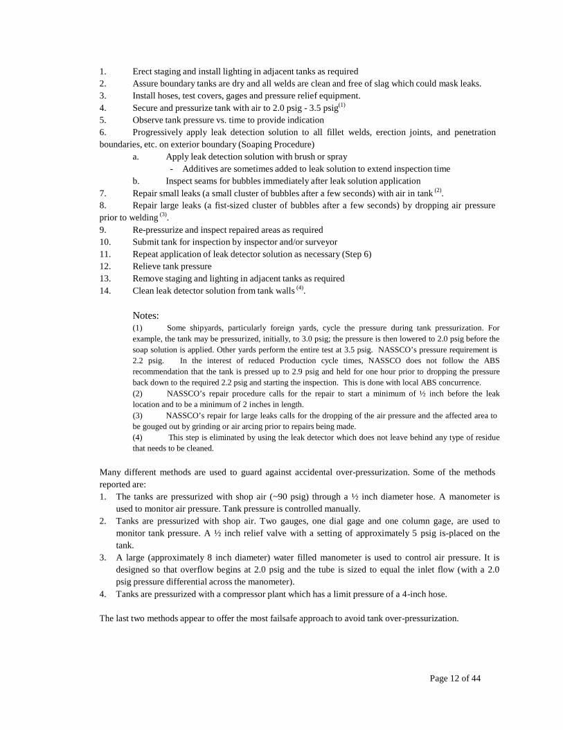
1. Erect staging and install lighting in adjacent tanks as required 2. Assure boundary tanks are dry and all welds are clean and free of slag which could mask leaks. 3. Install hoses, test covers, gages and pressure relief equipment. 4. Secure and pressurize tank with air to 2.0 psig - 3.5 psig(1)
5. Observe tank pressure vs. time to provide indication 6. Progressively apply leak detection solution to all fillet welds, erection joints, and penetration boundaries, etc. on exterior boundary (Soaping Procedure)
a. Apply leak detection solution with brush or spray - Additives are sometimes added to leak solution to extend inspection time
b. Inspect seams for bubbles immediately after leak solution application 7. Repair small leaks (a small cluster of bubbles after a few seconds) with air in tank (2). 8. Repair large leaks (a fist-sized cluster of bubbles after a few seconds) by dropping air pressure prior to welding (3). 9. Re-pressurize and inspect repaired areas as required 10. Submit tank for inspection by inspector and/or surveyor 11. Repeat application of leak detector solution as necessary (Step 6) 12. Relieve tank pressure 13. Remove staging and lighting in adjacent tanks as required 14. Clean leak detector solution from tank walls (4).
Notes: (1) Some shipyards, particularly foreign yards, cycle the pressure during tank pressurization. For example, the tank may be pressurized, initially, to 3.0 psig; the pressure is then lowered to 2.0 psig before the soap solution is applied. Other yards perform the entire test at 3.5 psig. NASSCO’s pressure requirement is 2.2 psig. In the interest of reduced Production cycle times, NASSCO does not follow the ABS recommendation that the tank is pressed up to 2.9 psig and held for one hour prior to dropping the pressure back down to the required 2.2 psig and starting the inspection. This is done with local ABS concurrence. (2) NASSCO’s repair procedure calls for the repair to start a minimum of ½ inch before the leak location and to be a minimum of 2 inches in length. (3) NASSCO’s repair for large leaks calls for the dropping of the air pressure and the affected area to be gouged out by grinding or air arcing prior to repairs being made. (4) This step is eliminated by using the leak detector which does not leave behind any type of residue that needs to be cleaned.
Many different methods are used to guard against accidental over-pressurization. Some of the methods reported are: 1. The tanks are pressurized with shop air (~90 psig) through a ½ inch diameter hose. A manometer is
used to monitor air pressure. Tank pressure is controlled manually. 2. Tanks are pressurized with shop air. Two gauges, one dial gage and one column gage, are used to
monitor tank pressure. A ½ inch relief valve with a setting of approximately 5 psig is-placed on the tank.
3. A large (approximately 8 inch diameter) water filled manometer is used to control air pressure. It is designed so that overflow begins at 2.0 psig and the tube is sized to equal the inlet flow (with a 2.0 psig pressure differential across the manometer).
4. Tanks are pressurized with a compressor plant which has a limit pressure of a 4-inch hose.
The last two methods appear to offer the most failsafe approach to avoid tank over-pressurization.
Page 13 of 44
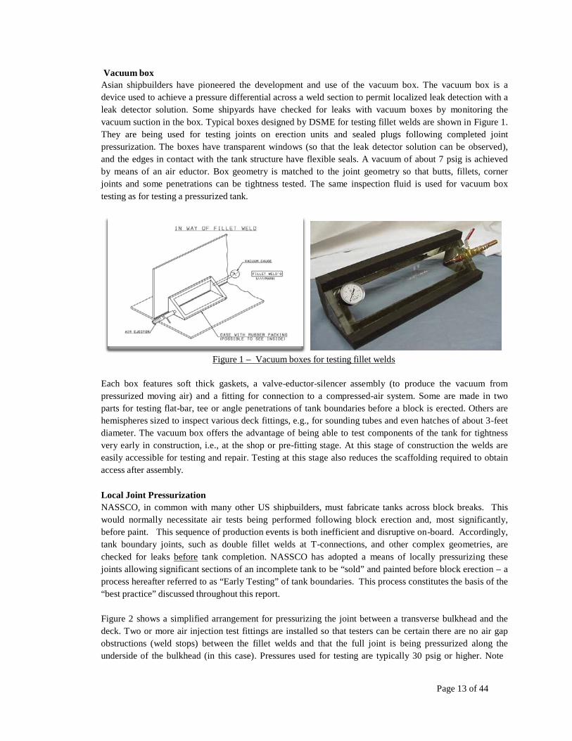
Vacuum box Asian shipbuilders have pioneered the development and use of the vacuum box. The vacuum box is a device used to achieve a pressure differential across a weld section to permit localized leak detection with a leak detector solution. Some shipyards have checked for leaks with vacuum boxes by monitoring the vacuum suction in the box. Typical boxes designed by DSME for testing fillet welds are shown in Figure 1. They are being used for testing joints on erection units and sealed plugs following completed joint pressurization. The boxes have transparent windows (so that the leak detector solution can be observed), and the edges in contact with the tank structure have flexible seals. A vacuum of about 7 psig is achieved by means of an air eductor. Box geometry is matched to the joint geometry so that butts, fillets, corner joints and some penetrations can be tightness tested. The same inspection fluid is used for vacuum box testing as for testing a pressurized tank.
Figure 1 – Vacuum boxes for testing fillet welds
Each box features soft thick gaskets, a valve-eductor-silencer assembly (to produce the vacuum from pressurized moving air) and a fitting for connection to a compressed-air system. Some are made in two parts for testing flat-bar, tee or angle penetrations of tank boundaries before a block is erected. Others are hemispheres sized to inspect various deck fittings, e.g., for sounding tubes and even hatches of about 3-feet diameter. The vacuum box offers the advantage of being able to test components of the tank for tightness very early in construction, i.e., at the shop or pre-fitting stage. At this stage of construction the welds are easily accessible for testing and repair. Testing at this stage also reduces the scaffolding required to obtain access after assembly.
Local Joint Pressurization NASSCO, in common with many other US shipbuilders, must fabricate tanks across block breaks. This would normally necessitate air tests being performed following block erection and, most significantly, before paint. This sequence of production events is both inefficient and disruptive on-board. Accordingly, tank boundary joints, such as double fillet welds at T-connections, and other complex geometries, are checked for leaks before tank completion. NASSCO has adopted a means of locally pressurizing these joints allowing significant sections of an incomplete tank to be “sold” and painted before block erection – a process hereafter referred to as “Early Testing” of tank boundaries. This process constitutes the basis of the “best practice” discussed throughout this report.
Figure 2 shows a simplified arrangement for pressurizing the joint between a transverse bulkhead and the deck. Two or more air injection test fittings are installed so that testers can be certain there are no air gap obstructions (weld stops) between the fillet welds and that the full joint is being pressurized along the underside of the bulkhead (in this case). Pressures used for testing are typically 30 psig or higher. Note
Page 14 of 44
from the photograph insert that the test fittings are grooved with a 1/8 inch slot to allow an air path behind the fitting into the fillet weld gap. Because of the small areas exposed to the pressure, there is little risk of over pressurization. A leak detection solution is applied to both sides of the joint used to detect leaks. After testing, the air injection fittings are welded closed to seal the joint. At NASSCO, this final plug weld is checked after tank completion using a vacuum box. Another advantage to this type of testing is that both sides of the bulkhead are checked for leaks and both sides are repaired where as with the traditional method of air testing, a completed tank on board only one side of the bulkhead is repaired.
Test Fitting Inlet Pressure Gauge
Inlet Fillet weld
Air path
Figure 2 - Simplified local joint pressurization arrangement
Joints at tank penetrations and the penetrations of longitudinal structure through transverse bulkheads often cannot be easily tested by the use of vacuum boxes. The complex geometry of these penetrations makes the design and sealing of boxes prohibitive. Hence, NASSCO also tests bulkhead penetrations using localized pressurization behind the weld and is developing methods to test pipe interfaces, collar, sleeves and access panels (e.g. manholes) using similar methods.
Magnetic Particle Inspection (MPI) Test MPI, is a Non-Destructive Test (NDT) process for detecting surface and slightly subsurface discontinuities in ferroelectric materials such as iron, nickel, cobalt, and some of their alloys. At NASSCO, the process is used primarily to identify welding imperfections at tank penetrations such as pipes, collars, sleeves and access panels. However, NASSCO has found MPI to be inconclusive on occasion and difficult to administer to all weld surfaces of complex fittings. Accordingly, NASSCO is following the example of those best practices from many Asian shipyards in air testing the weld seams using local joint pressurization. However, where vacuum boxes, full tank or local joint air pressurization cannot be performed, MPI is generally the best and least invasive alternative.
The MPI process puts a magnetic field into the part. The presence of a surface or subsurface discontinuity in the material allows the magnetic flux to bridge the air gap created by a discontinuity in the surface test area. Ferrous iron particles are then applied to the part. The particles may be dry or in a wet suspension. If an area of flux leakage is present, the particles will be attracted to this area. The particles will build up at the area of leakage and form what is known as an “indication”. The indication can then be evaluated to determine what it is, what may have caused it, and what action should be taken, if any.
NASSCO uses a series of hand-held devices known as the magnetic yoke that induces a magnetic field between two poles. Common applications are ideal for shipyard inspections and those with limited access.
The disadvantage of magnetic yokes is that they only induce a magnetic field between the poles so large- scale inspections using the device can be time-consuming. For proper inspection, the yoke needs to be rotated 90 degrees for every inspection area to detect horizontal and vertical discontinuities. (see Figures 3a & 3b)
Figure 3a - A NDT technician performs MPI on a pipe to check for stress corrosion cracking
Figure 3b - A close-up of the surface of the pipe showing indications of stress corrosion cracking (two clusters of small black lines) revealed by MPI.
There are several types of electrical currents used in MPI. For a proper current to be selected, part geometry, material, the type of discontinuity, and field penetration must be considered:
Alternating current (AC) is commonly used to detect surface discontinuities. Using AC to detect
subsurface discontinuities is limited due to what is known as the skin effect, where the current runs along the surface of the part. Because the current alternates in polarity at 50 to 60 cycles per second it does not penetrate much past the surface of the test object. This means the magnetic domains will only be aligned equal to the distance AC current penetration into the part. The frequency of the alternating current determines how deep the penetration.
Direct current (DC, full wave DC) is used to detect subsurface discontinuities where AC cannot penetrate deep enough to magnetize the part at the depth needed. The amount of magnetic penetration depends on the amount of current through the part. DC is also limited on very large cross-sectional parts in terms of how effectively it will magnetize the part.
The piece can be magnetized by direct or indirect magnetization. Direct magnetization occurs when the electric current is passed through the test object and a magnetic field is formed in the material. Indirect magnetization occurs when no electric current is passed through the test object, but a magnetic field is induced from an outside source. NASSCO normally carries out direct magnetization methods due to the test locations and the typical sizes of the parts being assessed.
Under normal circumstances, MPI is less reliable than air pressure testing in detecting porosity or tight air leaks in a weld. However, Magnetic Particle testing compensates for air/leak testing in its ability to detect linear indications such as lack-of-fusion or cracks thereby creating another opportunity to closely evaluate the weld by visual inspection.
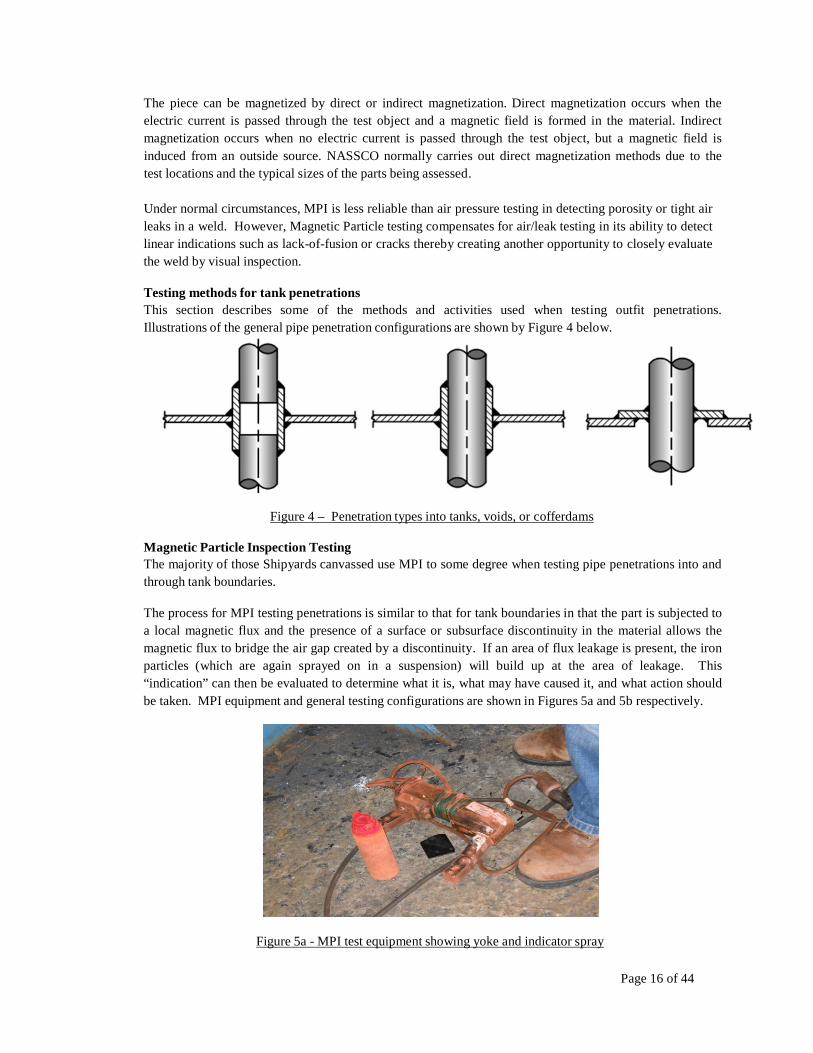
Testing methods for tank penetrations This section describes some of the methods and activities used when testing outfit penetrations. Illustrations of the general pipe penetration configurations are shown by Figure 4 below.
Figure 4 – Penetration types into tanks, voids, or cofferdams
Magnetic Particle Inspection Testing The majority of those Shipyards canvassed use MPI to some degree when testing pipe penetrations into and through tank boundaries.
The process for MPI testing penetrations is similar to that for tank boundaries in that the part is subjected to a local magnetic flux and the presence of a surface or subsurface discontinuity in the material allows the magnetic flux to bridge the air gap created by a discontinuity. If an area of flux leakage is present, the iron particles (which are again sprayed on in a suspension) will build up at the area of leakage. This “indication” can then be evaluated to determine what it is, what may have caused it, and what action should be taken. MPI equipment and general testing configurations are shown in Figures 5a and 5b respectively.
Figure 5a - MPI test equipment showing yoke and indicator spray
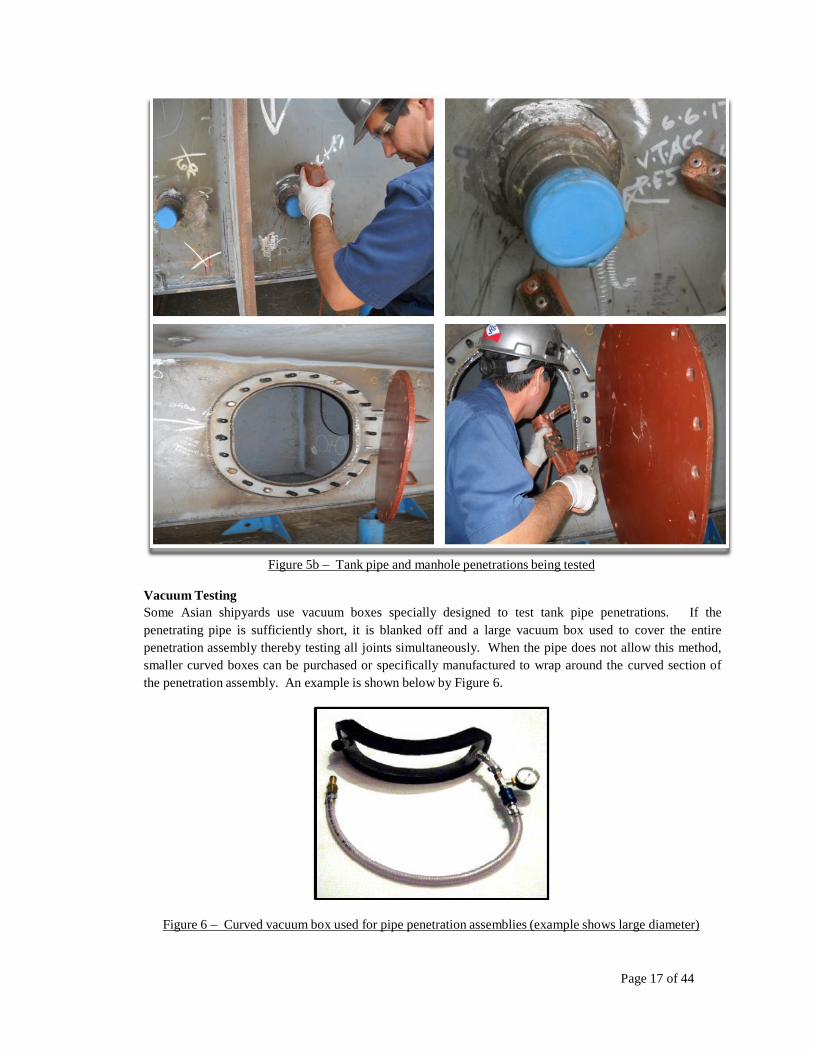
Figure 5b – Tank pipe and manhole penetrations being tested
Vacuum Testing Some Asian shipyards use vacuum boxes specially designed to test tank pipe penetrations. If the penetrating pipe is sufficiently short, it is blanked off and a large vacuum box used to cover the entire penetration assembly thereby testing all joints simultaneously. When the pipe does not allow this method, smaller curved boxes can be purchased or specifically manufactured to wrap around the curved section of the penetration assembly. An example is shown below by Figure 6.
Figure 6 – Curved vacuum box used for pipe penetration assemblies (example shows large diameter)
Page 18 of 44
Local Joint Pressurization As previously mentioned, MPI testing is generally not 100% successful. In practice, the MP test is good for identifying major cracks and weld flaws but is not able to clearly identify pinhole flaws in the weld joints. Such defects would be evident through air tests. The Korean yards, in particular, are leading in the practice of fillet weld air tests for manholes, penetrations and other outfit parts.
NASSCO’s Key Measures and success factors It is a general but universally held shipbuilding view that the earlier a task can be completed in the shipbuilding process, the lower the production cost. NASSCO often refers to the 1-3-8 rule in that: for any production task that could have occurred in the shop (or preferably at a Supplier’s manufacturing facility), the same task would cost 3 times as much if installed on the ground (on-block), or 8 times as much when installed on-board after ship erection. Figure 7 below illustrates.
Figure 7 – Production cost escalation through Stages of Construction
Cost escalates by a factor of 1 – 3 – 8 as work transfers from a shop setting – to on-ground – to on-board
The basic argument in favor of early air testing of tank boundaries is therefore, not that it is cheaper, or even more efficient than a fully completed tank air test. The overwhelming advantage is in that blasting and painting (B&P) the tank can be completed either in a B&P facility or on the ground immediately following the air test. This nullifies the majority of the escalation caused by deferring all B&P to on-board.
NASSCO’s philosophy for Tank Testing is that this should be carried out using air tests as early as possible during the construction cycle. In other words, as soon as any parts are assembled which are in way of a tight boundary, the boundary weld(s) shall be subjected to air tests.
Page 19 of 44
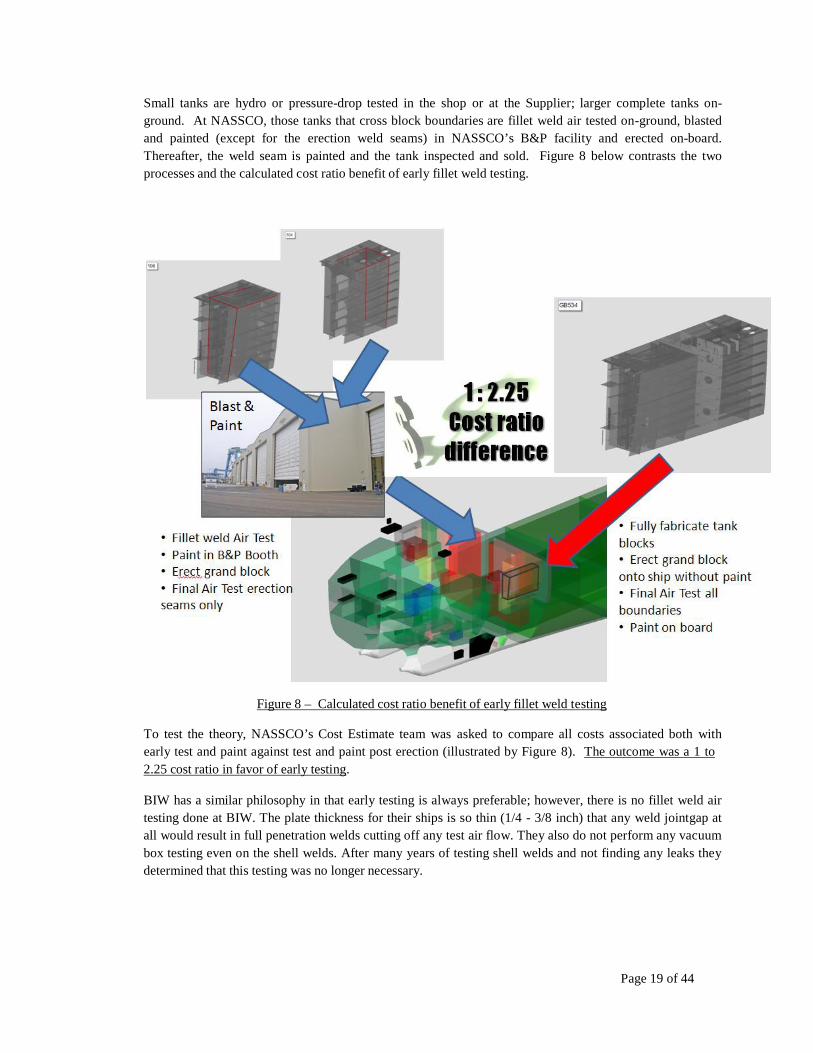
Small tanks are hydro or pressure-drop tested in the shop or at the Supplier; larger complete tanks on- ground. At NASSCO, those tanks that cross block boundaries are fillet weld air tested on-ground, blasted and painted (except for the erection weld seams) in NASSCO’s B&P facility and erected on-board. Thereafter, the weld seam is painted and the tank inspected and sold. Figure 8 below contrasts the two processes and the calculated cost ratio benefit of early fillet weld testing.
Figure 8 – Calculated cost ratio benefit of early fillet weld testing
To test the theory, NASSCO’s Cost Estimate team was asked to compare all costs associated both with early test and paint against test and paint post erection (illustrated by Figure 8). The outcome was a 1 to 2.25 cost ratio in favor of early testing.
BIW has a similar philosophy in that early testing is always preferable; however, there is no fillet weld air testing done at BIW. The plate thickness for their ships is so thin (1/4 - 3/8 inch) that any weld jointgap at all would result in full penetration welds cutting off any test air flow. They also do not perform any vacuum box testing even on the shell welds. After many years of testing shell welds and not finding any leaks they determined that this testing was no longer necessary.
Page 20 of 44
Through these types of early testing, the following success factors are realized:
1. Blasting and painting of tanks and their boundaries will be maximized prior to the block erection phases.
2. Masking and taping of welds will be extensively reduced at the block erection phases, thus improving the effectiveness of the Blast & Paint Facility.
3. Higher levels of block completion will be achieved. 4. Overall costs to customer/owner will be reduced. 5. Production Cycle will be reduced. 6. Hand-offs (transfer of work to a later stage of construction) will be reduced. 7. Re-work (weld repairs, re-testing and re-painting) will be reduced during the block erection phases. 8. Tank Testing, during the block erection phases is minimized. 9. The overall testing process will be more efficient and improved. 10. Overall Quality will be improved.
Page 21 of 44
3.3. IDENTIFYING COMPLEX GEOMETRY BOUNDARIES
A complex-geometry boundary can be defined as a structural arrangement that includes interface between more than 2 single flat and/or curved entities. The objective in identifying such boundaries is to better understand their weld interface geometry and, in particular, to be able to predict the air flow inside tank boundary structural welds. This prediction helps to establish the best locations of air injection fittings used to test boundary and outfit penetration welds prior to the tank completion - ultimately enabling blocks to be painted at an earlier stage of construction. Figure 9 below shows an integral tank (potable water) with no complex boundaries: the majority of the structural stiffening members are welded externally, and there is the minimum of penetrations. This tank could be easily pressure tested and painted prior to erection.
Figure 9 – Integral tank with no complex geometry boundaries
Conversely, Figure 10 shows a very large cargo tank that comprises 12 sub-blocks. This example illustrates many complex geometry boundaries each being a potential barrier to conducting a fillet weld air test during pre-erection for which specific planning and PI would be required.
Figure 10 – Large Cargo tank with many complex geometry boundaries
Page 22 of 44
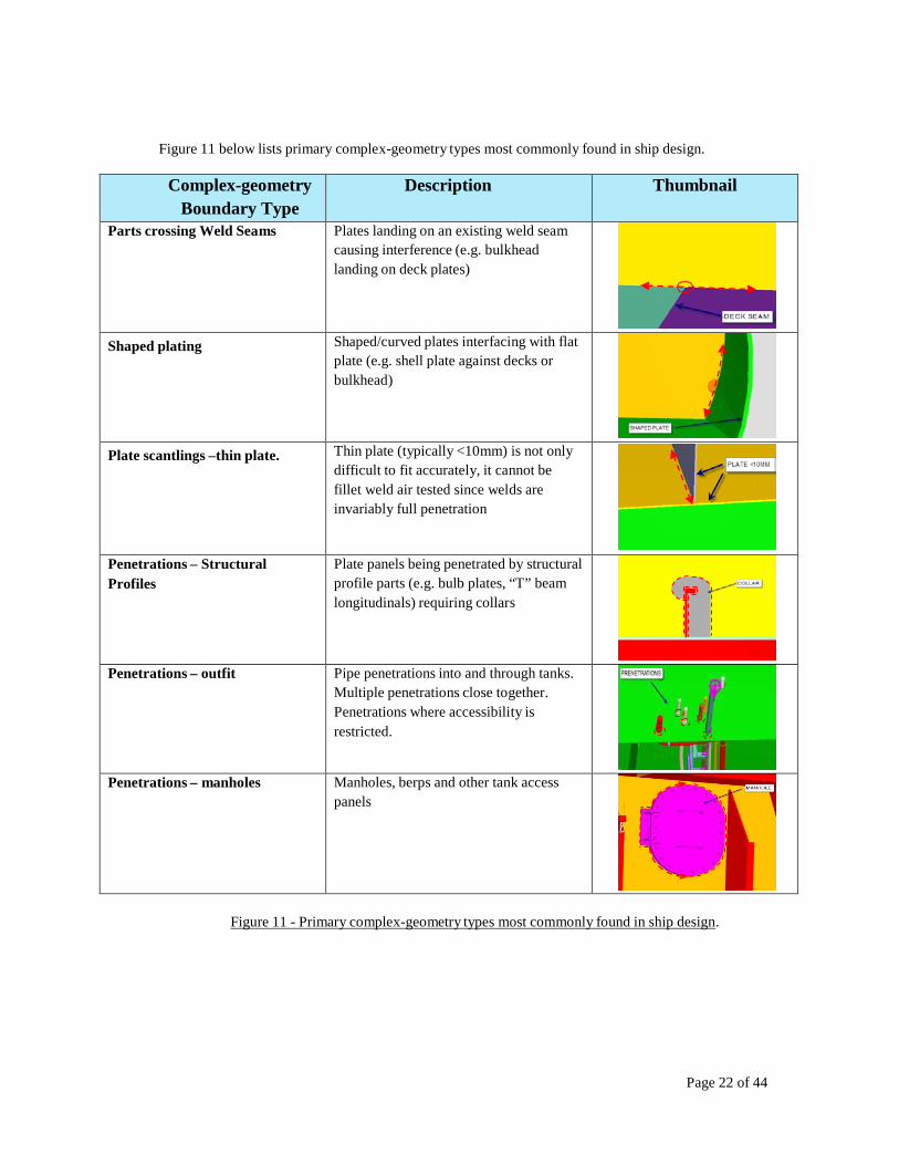
Figure 11 below lists primary complex-geometry types most commonly found in ship design.
Complex-geometry Boundary Type
Description Thumbnail
Parts crossing Weld Seams Plates landing on an existing weld seam causing interference (e.g. bulkhead landing on deck plates)
Shaped plating Shaped/curved plates interfacing with flat plate (e.g. shell plate against decks or bulkhead)
Plate scantlings –thin plate. Thin plate (typically <10mm) is not only difficult to fit accurately, it cannot be fillet weld air tested since welds are invariably full penetration
Penetrations – Structural Profiles
Plate panels being penetrated by structural profile parts (e.g. bulb plates, “T” beam longitudinals) requiring collars
Penetrations – outfit Pipe penetrations into and through tanks. Multiple penetrations close together. Penetrations where accessibility is restricted.
Penetrations – manholes Manholes, berps and other tank access panels
Figure 11 - Primary complex-geometry types most commonly found in ship design.
Page 23 of 44
3.4. DETERMINATION OF IMPACTS OF OWNER/CLASSIFICATION SOCIETY
REQUIREMENTS
General Classification Rules that govern tank testing for integral ship tanks are summarized in this section. The edition of the rules which was used to prepare the summary is listed below. In most cases, the classification societies abstracted those sections of the rules which were appropriate. Where appropriate, rule specifics are cited in this section together with application details. However, this section is not intended to duplicate large parts of the referenced society rules for the purposes of detail engineering – this is much better served through reference to the rules themselves.
Agency – American Bureau of Shipping (ABS): 2012 Rules for Building and Classing Steel Vessels Agency – Lloyds Register of Shipping: Abstracts from Steel Ship Rules – 2008 Agency – Bureau Veritas: Abstracts from rules for the construction and classification of Steel Vessels
Types of Testing The Classification Societies’ rules for testing integral ship tanks are very similar and also show no major difference to that of the US Coast Guard Rules. The societies require hydrostatic testing (1) of all tanks, except those for which air testing is permitted. ABS, for example, requires that, “all gravity tanks, excluding independent tanks of less than 5 m3 (176 ft3) in capacity, and other boundaries required to be watertight or weather-tight are to be tested and proven tight or structurally adequate”. Tests must be carried out in the presence of the Surveyor at a stage sufficiently close to completion for all attachments, outfitting or penetrations which may affect the strength or tightness of the structure have been completed, and before any ceiling and cement work is applied over joints. When an air test is an alternative, permission to substitute the air tests must be obtained from the local surveyor. Similarly, hydro-pneumatic testing may also be approved in lieu of hydrostatic testing. ABS requires a hydrostatic test for critical boundaries (2).
Notes: (1) ABS has greater confidence in a hydrostatic test for leak detection. This confidence is based on many
years of successful use of water and easier sighting of leaks by the surveyor. LNG ships require complete hydrostatic testing of integral tanks for safety reasons and for compliance with IMCO guidelines. (2) Critical boundaries are those in which leaks could be dangerous or costly, in terms of damage produced or the expense of repair.
Air testing is permitted by the Societies on large tanks for which hydrostatic tests are impractical. By implication, all air testing is to be performed prior to launch. Both ABS and Lloyds Register require that the air tests be supplemented by a hydrostatic test although dispensation may be sought. One or two of each representative tank to be air tested may be chosen by the surveyor for hydrostatic testing. If any anomalies are detected, a complete hydrostatic survey may be required.
Test Procedures Specific procedures for air testing are not well defined in the rules. Both ABS and Lloyds cite identical procedures in that air testing should be carried out by applying an efficient indicating liquid, e.g. soapy water solution, to the weld or outfitting penetration being tested, while the tank or compartment is subject to an air pressure of at least 0,15 bar (0,15 kgf/cm2). Three societies, ABS, Bureau Veritas and Lloyds Register require that the pressure be raised above the inspection pressure, to 0,2 bar (0,2 kgf/cm2) and held for up to one hour to reach a stabilized state (with a minimum number of personnel in the vicinity) and then dropping down to the inspection pressure. Bureau Veritas will accept alternate tank testing procedures,
Page 24 of 44
providing the substituted methods can be shown to be as conclusive in demonstrating tightness and structure adequacy as the standard testing.
The Societies generally prefer that hydrostatic testing take place before launch. Where this is impractical, the tests may be deferred until after launch. When the hydrostatic tests are performed after launch, a checkerboard pattern for filling the tanks is generally allowed. This serves two purposes: firstly, checkerboard testing permits inspection of all boundaries without having to fill each tank with water; secondly, the pattern is chosen to provide a load distribution and draft which is representative of structural stress during service conditions. ABS has determined that integral tanks can be tested in this way only to determine tightness – except when testing vessels longer than 750 feet(3) where hydrostatic tests are for verification of structural strength as well as tightness. Lloyds Register requires that when checkerboard testing is complete, the checkerboard pattern is reversed and the boundaries are re-inspected from the other side. Tanks to be tested for structural adequacy are selected so that all representative structural members are tested for the expected tension and compression.
Note (3) For oil tankers under 750 ft in length, the derivation of structural strength from ship scantlings is determined by ABS formula. A long history of successful designs by these formulas has established confidence in them and in the values assigned to their coefficients. For tankers over 750 ft in length, finite element methods are generally used to establish ship scantlings and ABS requires the hydrostatic test for confirmation of the structure in the cargo tank area.
Application of Coatings ABS and Lloyds Register permit coatings to be applied to all surfaces except manual welds prior to testing. ABS states that final coating may be applied prior to the hydraulic testing, provided an air test is carried out before the application of the final coating. For all manual or semi-automatic erection welds and all fillet weld tank boundary connections including penetrations, the final coating is to be applied after air testing. For other welds, the final coating may be applied prior to air testing providing the surveyor, after examination prior to the application of the coating, is satisfied with the weld. Special coatings (4) are approved by ABS and are applied to reduce corrosion in the ship tanks. Most common coatings are zinc and epoxies.
Note (4) Hydrostatic tests are permitted after special coatings are applied because such a test closely represents future service conditions. Air tests are low pressure tests which do not simulate service conditions and so must be performed before the coatings are applied. ABS believes that most special coatings may seal some openings during an air test that will subsequently leak in service when subjected to a head of dense liquid.
Inspection requirements for tank boundary joints In general, ABS requires that all fillet weld boundary connections, erection joints, and boundaries of manhole covers, etc., are examined under air test conditions using a suitable leak detection solution. Other welded joints (at the discretion of the surveyor) may also be required to be similarly examined. ABS exacts more explicit inspection requirements for air tests because a close visual examination is required to detect leaks. This is not the case with hydrostatic tests, where leaks are more easily detected without close inspection.
A visual examination (before coatings are applied) of automatic butt and seam welds is usually judged by the local surveyor to be sufficient to assure tank tightness in these regions since most leaks occur in manual fillet welds, erection joints, and penetrations.
Page 25 of 44
Owner Requirements - Department of the Navy The Department of the Navy has specific requirements for compartment testing on its ships. Two types of tests are used during construction to verify liquid tightness of compartments. These tests are called “completion tests” and “tightness”. The tests are performed after all structural work which might affect tightness has been completed.
Completion tests are designed to verify adequate tightness of a completed ship compartment designated as air tight, water tight, oil tight or fume tight. The tank is pressurized with air or liquid pressure and a lack of tightness as detected by observing a drop in air pressure or liquid head. The air pressure for water tight or oil tight compartments is 2 psi except where the structure is designed to withstand a lower pressure, in which case the design pressure is used. A compartment is considered tight providing no leakage is observed in ten minutes.
Tightness tests are designed to assure the specified level of tightness under reasonable service conditions. The tests are performed by applying water pressure equivalent to the design head of the structure. Ship tanks, cofferdams, and void spaces are subject to tightness testing. The tanks to be tested are selected by the supervisor, and should be representative of each type of tank. At least ten percent, but not less than one of each type of tank, cofferdam and void shall be tested by flooding with water to the design liquid head. If during testing, and tank shows signs of leakage, it is declared defective, repaired and retested. In addition, the tanks, cofferdams or voids adjacent to the defective tank shall be tested for tightness. If no tanks, cofferdams or voids are adjacent to the defective tank, then at least one other space in a location similar in construction to the defective space shall be tested for tightness.
Impacts of Owner/Classification Society Requirements: 1. Hydrostatic testing on large and very large (e.g. cargo) tanks is impractical (and structurally
inadvisable) for most shipyards and generally testing must occur after launch. 2. Hydrostatic tests on tanks crossing block breaks cannot be completed until after block erection. 3. Unless dispensation is obtained to carry out air testing, delaying tests to immediately prior to, or after,
launch has profound impacts on production efficiencies and cost – particularly if final paint has been subsequently delayed.
Page 26 of 44
3.5. INVESTIGATION OF METHODS OF MANAGEMENT OF THE TESTING
PROCESS
Shipyards within the Continental US along with those overseas will necessarily have distinct management processes to facilitate early testing of tank boundaries (characterized by use of the fillet weld air test). However, there are several common elements to any management process:
1. Identification of tank compartments 2. Identification of test boundaries by block, assembly and Stage of Construction (SOC) 3. Segregation of boundaries to be tested before paint subject to fillet weld air test 4. Producing fillet weld air test Production Information (PI) 5. Carry out air tests (with ABS/regulatory witness as required) 6. Document results
This section describes the management processes behind these process elements – including sources of input, primary customers along with the PI process itself. A representative methodology is represented by Figure 12.
Figure 12 - Representative testing management process
NASSCO’s procedure for identifying air tests and producing Production Information (PI) Prior to starting this process, it is assumed that all oilstops, ratholes, weld wraps etc. required to facilitate the Air Tests are in place; however, part of the process is to check this. The following tasks are performed by NASSCO Engineering Design personnel:
Page 27 of 44
Create Test Markups Test mark-ups are produced for identifying the fillet and/or partial penetration welds along tank boundaries which will be subjected to pressure testing (2 examples shown by Figures 13a and 13b). They are a necessary part of the process as they provide information with clarity and understanding for the task of creating air test PI drawings and the interrogation of the existing structure via the 3D Model. Depending on the complexity of the ships structure, the mark-ups may be either 3D Screenshots from the Model, or prints of existing PI/Assembly drawings, or a combination of both. A list of the air tests by assembly may also be produced, summarizing the information on the mark-ups.
The following information (as applicable & if not already existing) should be added to the mark-ups:
Orientation of Views (Fwd/Aft/Port/Stbd/Top/Btm) as applicable.
Grand Block, Block & Assembly Numbers.
Tank Identification (Names & Compartment Numbers).
Tank Boundaries.
Ship Location of Tank(s) relative to Long & Frame Nos.
Air Test identification by assembly.
Assigned Air Test numbers per assembly.
Assigned PI Drawing numbers.
Figure 13a - Air test markup
Page 28 of 44
Create Air Test Matrix
Figure 13b - Air test markup
During creation of the mark-ups, an Air Test Matrix (electronic spreadsheet) is produced that lists all of the planned air tests. It is used primarily by test personnel for tracking tank completion. It may also used in Engineering for planning the PI and tracking the progress of the mark-ups and PI drawings. The following information should be added to the matrix:
Compartment Number
Tank Name
Ship Location of Tank (Port/Stbd/Frame Range)
Block No.
Assembly No.
PI Drawing No.
Air Test Nos. Several of these elements are individually filterable so that different lists may be generated, as required. Figure 14 is an example of the Air Test Matrix.
Figure 14 - Example of the Air Test Matrix
Page 29 of 44
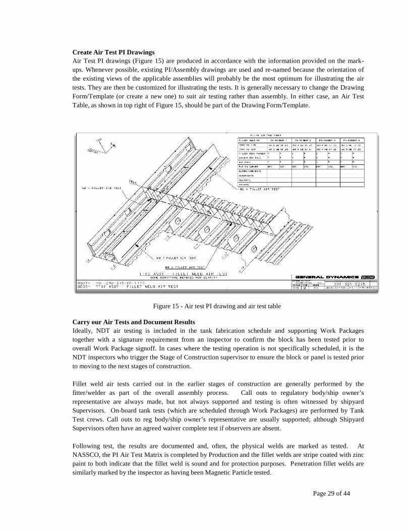
Create Air Test PI Drawings Air Test PI drawings (Figure 15) are produced in accordance with the information provided on the mark- ups. Whenever possible, existing PI/Assembly drawings are used and re-named because the orientation of the existing views of the applicable assemblies will probably be the most optimum for illustrating the air tests. They are then be customized for illustrating the tests. It is generally necessary to change the Drawing Form/Template (or create a new one) to suit air testing rather than assembly. In either case, an Air Test Table, as shown in top right of Figure 15, should be part of the Drawing Form/Template.
Figure 15 - Air test PI drawing and air test table
Carry our Air Tests and Document Results Ideally, NDT air testing is included in the tank fabrication schedule and supporting Work Packages together with a signature requirement from an inspector to confirm the block has been tested prior to overall Work Package signoff. In cases where the testing operation is not specifically scheduled, it is the NDT inspectors who trigger the Stage of Construction supervisor to ensure the block or panel is tested prior to moving to the next stages of construction.
Fillet weld air tests carried out in the earlier stages of construction are generally performed by the fitter/welder as part of the overall assembly process. Call outs to regulatory body/ship owner’s representative are always made, but not always supported and testing is often witnessed by shipyard Supervisors. On-board tank tests (which are scheduled through Work Packages) are performed by Tank Test crews. Call outs to reg body/ship owner’s representative are usually supported; although Shipyard Supervisors often have an agreed waiver complete test if observers are absent.
Following test, the results are documented and, often, the physical welds are marked as tested. At NASSCO, the PI Air Test Matrix is completed by Production and the fillet welds are stripe coated with zinc paint to both indicate that the fillet weld is sound and for protection purposes. Penetration fillet welds are similarly marked by the inspector as having been Magnetic Particle tested.
Page 30 of 44
BIW Tank testing Process.
For tanks that are completed within the confines of the block assembly, BIW performs a pressure test on the completed tank. The Tank Testers receive a work order that specifies the required test pressure along with the budget for the job. The tank is then sealed up using soft rubber gasket material glued to plywood as patches for any openings in the tank boundaries such as temporary access openings, and blanks or plugs for their piping systems. On some occasions, if the insert for the opening is on hinges and can be closed Production will forego the soft patch and close the insert, apply tack welds as necessary and tape the gap around the insert to hold pressure.
A test cover is installed on the tank opening that consists of 2 test fittings. One is for the gauge and the other is for the supply line and the relief valves. Gauges are calibrated monthly and the relief valves are of the spring loaded type and are also calibrated to a designated cracking pressure. In most cases, the supply line is a ½ inch air hose with quick disconnect fittings that attach to the supply manifold and then to the fitting on the test cover. The air pressure is regulated with a valve at the cover to prevent the relief valves from cracking. Tank testers will occasionally use a larger bore air supply line for larger tanks. When the required air pressure is attained, the Tank Tester will soap the boundaries of the tank to check for leaks using either a spray bottle or a garden type sprayer. The solution BIW use for detecting leaks is a combination of dish soap liquid mixed with water.
When leaks are located, they are marked and the air pressure is dropped in the tank (this is necessary as BIW only uses MIG welding and the air from the leak would blow the gas and prevent welding), the Tank Tester then calls for a Welder to make the repairs. The Welder will gouge out the defective weld and when the Welder has completed the repair the tank is once again pressed up to the required test pressure and the area is re-checked to verify repair was successful. Once the tank is completed, the Navy is notified, usually by a phone call, that the tank is ready for inspection. On final tests, there is an official callout procedure where the customer is given 24 hour notice and the appropriate documents are signed and forwarded to their Test Center. At the completion of the test, the pressure is released from the tank by opening the relief valve and the test equipment is removed.
On board testing (the final air test) is done following the same procedure as in the assembly area except, since there are no boundaries to check, it is simply a 10 minute no drop test. In the case of compartment testing there may be some allowable drop that is specified on the work instruction. Testers will also check any flanges where valves have been installed that may not have been present in the pre-erection testing.
Page 31 of 44
3.6. DOCUMENT OPPORTUNITIES FOR CONTINUOUS IMPROVEMENT
Continuing from many of the initiatives and processes described earlier, this section discusses some of the lessons learned and improvement opportunities that are now being implemented both at NASSCO and at those shipyards interviewed. In particular, this section introduces some Asian innovations now being used increasingly in US shipyards for testing fillet welds on outfit penetrations. Those examples of outfit penetration air tests used in this section were designed, developed, and tested through this project.
Firstly, however, those complex geometries described in Section 3.3 are re-visited together with other producibility improvements that have been identified – primarily at NASSCO:
Parts crossing weld seams Plate panels being penetrated by other structural profile parts – bulbs, T’s, etc. Plate panels being penetrated by outfit parts – pipe collars, sleeves, manholes etc. Thin plate scantlings Shaped plating Corner snipes Tack weld locations Inspection and training
Parts crossing weld seams The example (Figure 16) of two horizontal deck plates intersecting a vertical bulkhead with a seam illustrates a complex geometry boundary in its “simplest” form. Unless noted in the Production Information (PI), the welder could burn a recess in the bulkhead plate to accommodate the seam. The left hand picture indicates attempted remediation of a seam that was not ground smooth prior to fitting crossing structure. An attempt has been made to burn the crossing plate in-way of the seam. The welding of the crossing member will invariably create a welded “stop” at this location because of too much undercut and, during air test, will prevent air from completing its path inside the full length of the boundary.
Best practice: To grind the seam flat at the site of the intersection (right hand photograph) thereby allowing fillet weld air to pass over the seam unrestricted. This can be achieved either through training and/or a notation on the PI drawing.
Attempted remediation
Grind seam flat in way of landing plate
Figure 16 – Parts crossing weld seams
Page 32 of 44
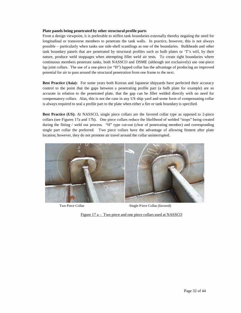
Plate panels being penetrated by other structural profile parts From a design viewpoint, it is preferable to stiffen tank boundaries externally thereby negating the need for longitudinal or transverse members to penetrate the tank walls. In practice, however, this is not always possible – particularly when tanks use side-shell scantlings as one of the boundaries. Bulkheads and other tank boundary panels that are penetrated by structural profiles such as bulb plates or ‘T’s will, by their nature, produce weld stoppages when attempting fillet weld air tests. To create tight boundaries where continuous members penetrate tanks, both NASSCO and DSME (although not exclusively) use one-piece lap joint collars. The use of a one-piece (or “H”) lapped collar has the advantage of producing an improved potential for air to pass around the structural penetration from one frame to the next.
Best Practice (Asia): For some years both Korean and Japanese shipyards have perfected their accuracy control to the point that the gaps between a penetrating profile part (a bulb plate for example) are so accurate in relation to the penetrated plate, that the gap can be fillet welded directly with no need for compensatory collars. Alas, this is not the case in any US ship yard and some form of compensating collar is always required to seal a profile part to the plate when either a fire or tank boundary is specified.
Best Practice (US): At NASSCO, single piece collars are the favored collar type as opposed to 2-piece collars (see Figures 17a and 17b). One piece collars reduce the likelihood of welded “stops” being created during the fitting / weld out process. “H” type cut-out (clear of penetrating member) and corresponding single part collar the preferred. Two piece collars have the advantage of allowing fitment after plate location; however, they do not promote air travel around the collar uninterrupted.
Two Piece Collar Single P iece Collar (favored)
Figure 17 a – Two piece and one piece collars used at NASSCO
Page 33 of 44
Figure 17b - Plate panels penetrated by other structural profile parts showing air paths
Plate panels being penetrated by outfit parts Full pressure testing apart, most US shipyards rely on magnetic particle testing to identify fillet weld defects in outfit parts that penetrate tank boundaries. But, although the MP test is good for identifying major cracks and weld flaws, it is not able to clearly identify pinhole flaws in the weld joints.
Best Practice – Pipe Penetrations. As stated throughout this project, small defects in fillet welds are more evident through local fillet weld air tests. Accordingly, several Asian yards (notably DSME) are adopting the practice of local fillet weld air tests for manholes, penetrations and other outfit parts. It was desirable during this project to physically demonstrate DSME’s fillet weld air test technology as it related to outfit parts. The design by Figures 18a and 18b show NASSCO’s first iteration, Rev (-).
Figure 18a – First iteration of NASSCO fillet weld air test fixture
a zero pressure at the guage.
Page 34 of 44
Figure 18b – First iteration of NASSCO fillet weld air test fixture (image)
The views and photograph above show a typical pipe with sleeve welded to a section of tank plate. Two test fittings have been integrated into the fillet weld interfacing the sleeve to the tank plate thereby allowing an air path into the air gap between the two fillet welds on opposing sides of the tank boundary against the outer face of the sleeve. When the 2 test fittings are connected to compressed air supply and guage (as shown) and leak detection solution applied on both top and bottom welds, defects in the weld can be easily seen (there were no defects in the case of this test).
To extend the test to include the 2 fillet welds interfacing the inside of the sleeve to the pipe (top and bottom), a 6mm hole was drilled centerline to the tapped hole in the test fittings through the sleeve (but not penetrating the pipe). This allowed the same air pressure that was pressurizing the air gap at the sleeve/tank boundary interface to also pressurize the air gap between the sleeve and the pipe. Figure 19 below shows all 4 fillet welds tested using this method.
1 3
4 2
Figure 19 – Four welds tested
The problem with this method is that air travelling from one test fitting to the other can do so (conceptually) clockwise or anticlockwise. Two or more inadvertant weld stops along either path would cause pockets in the air path possibly leading to false test results since the pressure guage would continue to show constant pressure using the “other” path. This problem was reduced with a second iteration, Rev (A), of the design that shortened the angular distance between the 2 test fittings (as shown by Figure 20) togeher with a weld stop deliberately placed between the fittings. This forced the air through a predictable path thereby reducing the risk of false results since even one inadvertant weld stop would be recorded with
Page 35 of 44
Figure 20 – Second iteration of NASSCO fillet weld air test fixture
A third, and possibly best option, is to dispense with the pipe sleeve and 2 test fittings and to fit a lapped collar (Figure 21). The collar has 2 tapped holes for air pressure and the guage, close enough to determine a predictable air flow.
Figure 21 – Pipe penetrations using lapped collar
Lapped collars can be used to advantage when dealing with multiple penetrations such as those shown by Figure 22. Identified sufficiently early in the design, these penetrations can be bundled and mounted onto one manifold lap plate (Figure 23).
Figure 22 - Multiple penetrations through tank boundaries
Page 36 of 44
Apart from the obvious production and installation benefits, this arrangement allows for all collar/tank interfaces to be tested in one event. It also allows for the lap plate/pipe interface welds to be tested in the shop prior to installation which, as was seen in section 3.3, can have upto a 3:1 production cost saving over the same work on-block. Note the same testing arrangement of tapped holes for the air test. These, in common with all previous examples would be welded closed post test and checked with a vacuum box.
Figure 23 – Multiple penetration manifold lap plate
Best Practice – Manholes. The manifold lap plate concept can be extended to manholes where, again, the same testing arrangement of tapped holes for the air test can be used. However, since the position of a manhole is fixed, a welded slot can be manufactured in the manhole ring to create an air stop between the pressure and guage tapped holes. This assures that the long air path is tested (Figure 24).
Thin Plate Figure 24 - Fillet weld air test in way of manhole ring
Scantlings with plate less than 10mm thick increase the likelihood of welded stops being inadvertently created during the normal fillet welding process. When very thin plates are used, full penetration welds become inevitable making any form of fillet weld air test unreliable.
Best Practice: This risk can be reduced by increased fitting accuracy and thus reducing gaps between the parts being welded. The same can be said when welding curved plates of any thickness. BIW uses thin plate extensively and has little opportunity to use fillet weld air tests since, by necessity, all welds are full penetration. BIW has introduced one method of early testing by designing partial tank boundaries adjacent to block breaks. Accordingly, for block assemblies that contain partial non-tight tank boundaries, all openings are sealed allowing them to apply pressure to the partial tank. For areas such as rat holes, sniped
Page 37 of 44
corners, and longs passing through the bulkheads that have a collar sized opening around them, the testers use tin plating designed to fit these specific areas and then apply tape around the edges to acquire an air tight boundary. Lightning holes are sealed in the same manner as temporary access openings using a rubber gasket/plywood patch. If leaks are located, the welder makes the repairs and then the area is rechecked.
Shaped Plate Shaped plate (Figure 25), either when butted together or to a flat plate also increase the likelihood of welded stops being inadvertently created during the normal fillet welding process. Unless edge accuracy is very high, gaps between the welded surfaces can become sufficiently wide that full penetration welds become inevitable making any form of fillet weld air test difficult.
Best Practice: This risk can be reduced by increased fitting accuracy and thus reducing gaps between parts being welded.
.
Corner Snipes
Figure 25 – Curved plate scantlings
10mm x 10mm corner snipes are typically added to aid fit-up where a third plate is added to accommodate an existing or planned continuous fillet weld on the first 2 plates - Figure 26 below illustrates. When these snipes do not fit accurately over and existing fillet weld, they are likely to create a welded “stop”.
Best Practice. Shipyards should ensure that Engineering PI and the drawing detailing the fillet weld test routes recognize the importance of sequencing plate installation in a way that the air gaps are preserved both between the first two plates and around the 3rd plate following installation.
3 2
1
Figure 26 – Corner snipes
Page 38 of 44
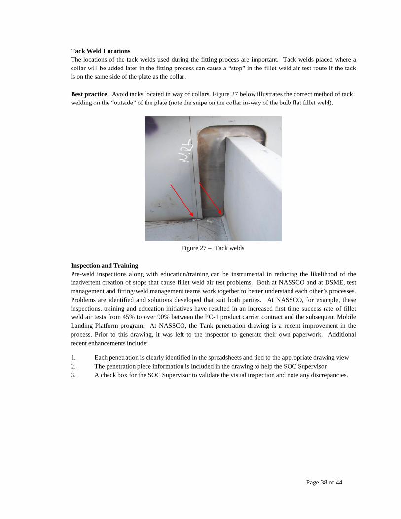
Tack Weld Locations The locations of the tack welds used during the fitting process are important. Tack welds placed where a collar will be added later in the fitting process can cause a “stop” in the fillet weld air test route if the tack is on the same side of the plate as the collar.
Best practice. Avoid tacks located in way of collars. Figure 27 below illustrates the correct method of tack welding on the “outside” of the plate (note the snipe on the collar in-way of the bulb flat fillet weld).
Figure 27 – Tack welds
Inspection and Training Pre-weld inspections along with education/training can be instrumental in reducing the likelihood of the inadvertent creation of stops that cause fillet weld air test problems. Both at NASSCO and at DSME, test management and fitting/weld management teams work together to better understand each other’s processes. Problems are identified and solutions developed that suit both parties. At NASSCO, for example, these inspections, training and education initiatives have resulted in an increased first time success rate of fillet weld air tests from 45% to over 90% between the PC-1 product carrier contract and the subsequent Mobile Landing Platform program. At NASSCO, the Tank penetration drawing is a recent improvement in the process. Prior to this drawing, it was left to the inspector to generate their own paperwork. Additional recent enhancements include:
1. Each penetration is clearly identified in the spreadsheets and tied to the appropriate drawing view 2. The penetration piece information is included in the drawing to help the SOC Supervisor 3. A check box for the SOC Supervisor to validate the visual inspection and note any discrepancies.
Page 39 of 44
3.7. DOCUMENT COORDINATION ISSUES BETWEEN STEEL AND OUTFIT
PLANNING PROCESSES
This section takes the outfit perspective and describes the relationship between the Steel and Outfit Planning functions since, in most shipyards (particularly in the US), these planning activities are carried out by separate departments.
Planning and Documentation As with steel structure boundary welds, the testing of outfit penetrations to tank boundaries ideally needs to be integrated into the production schedule and subsequently included in the work-packages - for which a formal testing schedule needs to be developed so that any required tests are performed at the earliest possible stage. Determining the need for penetration testing early-on can enable changes to the detail design so that connections (for blanking) might be located in places that make the tank easier to test. If the determination is done at the late stage of outfit planning (when detail design and definition of pipe spools is already done) it can require costly rework in order to make the changes that might be necessary for early penetration testing.
This is not true in many shipyards where penetration weld tests are not scheduled specifically. Accordingly, the testing operation is not part of the total schedule and is not part of the prior stage work- package as a prerequisite to be completed prior to the work-package being closed. In these shipyards, as with primary structure, it is the NDT inspectors who trigger the SOC supervisor to ensure the panel or fitting is tested prior to moving to the next stages of construction.
Prior to NDT, all penetrations on the boundary surface should be annotated as having been visually inspected by the Supervisor prior to release for test – accordingly, sign-off documentation should be in place confirming this has taken place. Similarly, following test, sign-off documentation should confirm that the test is complete and witnessed as appropriate. On occasion, only one side of a penetration can be tested - usually due to either a restricted access to both sides, or that only one side of the penetration has been welded. This means these penetrations cannot be fully tested and approved until both sides are welded. This will require the testing to be conducted at the next stage of construction and noted in the Inspectors Tank Penetration drawing as a traveling document to the next stage.
Page 40 of 44
3.8. APPLICATION OF AUTOMATION TOOLS FOR PRODUCING PRODUCTION
AND TEST INFORMATION
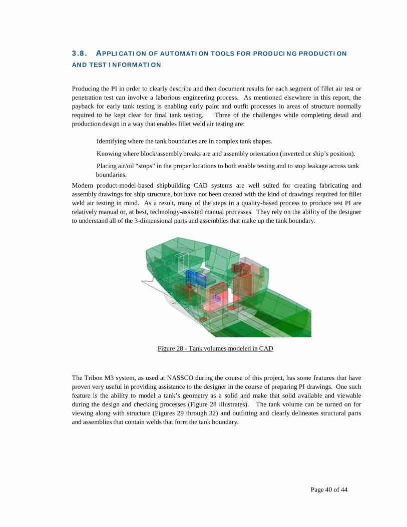
Producing the PI in order to clearly describe and then document results for each segment of fillet air test or penetration test can involve a laborious engineering process. As mentioned elsewhere in this report, the payback for early tank testing is enabling early paint and outfit processes in areas of structure normally required to be kept clear for final tank testing. Three of the challenges while completing detail and production design in a way that enables fillet weld air testing are:
Identifying where the tank boundaries are in complex tank shapes.
Knowing where block/assembly breaks are and assembly orientation (inverted or ship’s position).
Placing air/oil “stops” in the proper locations to both enable testing and to stop leakage across tank boundaries.
Modern product-model-based shipbuilding CAD systems are well suited for creating fabricating and assembly drawings for ship structure, but have not been created with the kind of drawings required for fillet weld air testing in mind. As a result, many of the steps in a quality-based process to produce test PI are relatively manual or, at best, technology-assisted manual processes. They rely on the ability of the designer to understand all of the 3-dimensional parts and assemblies that make up the tank boundary.
Figure 28 - Tank volumes modeled in CAD
The Tribon M3 system, as used at NASSCO during the course of this project, has some features that have proven very useful in providing assistance to the designer in the course of preparing PI drawings. One such feature is the ability to model a tank’s geometry as a solid and make that solid available and viewable during the design and checking processes (Figure 28 illustrates). The tank volume can be turned on for viewing along with structure (Figures 29 through 32) and outfitting and clearly delineates structural parts and assemblies that contain welds that form the tank boundary.
Page 41 of 44
Figure 29 - A hull block shown with tank volumes
When the tank volume is a component of an overall ship product model, it “knows” what other components penetrate its boundaries and also those that are adjacent to it. This is a very useful feature for checking structure and outfitting and also for planning purposes.
Figure 30 - View of tanks with penetrating outfitting components
Figure 31 - A tank showing adjacent structure and outfitting
Page 42 of 44
Another feature of modern shipbuilding CAD systems that assists in the process of creating accurate fillet weld air test drawings is their ability to visualize intermediate structural and outfit products at any step of the production process, or build strategy. In the Tribon M3 System, the Assembly Planning module groups parts and assemblies according to the agreed upon build strategy. A designer must account for the orientation and configuration of an assembly at the stage of construction where the fillet weld air test is applied.
A complimentary feature of Tribon M3 Assembly Planning is Weld Planning. Weld Planning is used to define all of the welds required at an assembly stage and is used for planning and budgeting for the welding processes required. Welds can then become part of the ship product model and can contain much valuable information such as which parts they connect, how long a welded segment is and at what stage they are accomplished. NASSCO’s initial investigations into extending this weld planning functionality into the fillet weld air testing process are promising. It is possible to modify attribute data for the welds that comprise the structural boundary of a tank – these are the welds that require early testing. Figure 32 illustrates.
Figure 32 – Example of tank boundary identification, penetrations, welds and test type
Automatic drawing creation is another feature of systems such as Tribon M3 and, if used in conjunction with automated weld planning and modeled tank boundary information, there is promise of being able to create a tool to remove many man-hours from the PI preparation process while also increasing the quality of the final design products. At the present time, NASSCO finds that it is not possible to bring all of the features described above together in a way that would allow for automating the drawing process. Weld attributes that we were able to store with a particular weld were not persistent – they were reset by other required operations on the assembly.
Page 43 of 44
The ability to create customized programs that control the features of shipbuilding CAD systems continue to offer promise in this area. NASSCO’s hope is that it will be possible in the near future with some cooperation from systems suppliers to allow us to create the necessary annotated drawing views automatically.
This ability would both aid in reducing the number of man-hours required to produce the PI, but also to shorten the cycle time of a process that necessarily fits in between detail and production design.
Page 44 of 44
4. CONCLUSION
Testing shipboard tank boundary and outfit penetration welds prior to tank completion is an important enabler for painting blocks at an earlier stage of construction. Traditionally, Class Society and Owner rules required that painting and outfitting must be held back from boundary welds for a tested tank until the final tank pressure test had been completed satisfactorily – often onboard. This significantly impairs the shipyard’s ability to complete outfitting and painting at the earliest, and most efficient, stage of construction. This report estimates that for any production task that could have occurred in the shop, the same task would cost 3 times as much if installed on the ground (on-block), or 8 times as much when installed on-board after ship erection. Cost estimates shown in this report show that the cost of delaying tank paint and test from on-block to on-board would escalate the production cost by 225%.
Utilizing knowledge gained from process improvements instituted at NASSCO, along with best practices from other leading US and Asian shipyards, this study describes ways to identify and optimize those testing methods currently mandated by Classification Societies and Owner requirements. In addition to investigating shipyard best practices for the testing of tank structural boundaries, this project also introduces methods to test outfit penetration welds prior to completion of the tank that they make-up. The project also includes research into automating the generation of Production Information of tank boundary tests as direct outputs from modern Computer Aided Design tools such as the Tribon M3, 3-D modeling system as used at NASSCO.
Through early testing, this project identifies several success factors: Firstly, blasting and painting of tanks and their boundaries will be maximized prior to the block erection phases and any masking and taping of welds will be extensively reduced. This improves the effectiveness of the Blast & Paint Facility and minimizes tank testing, during the block erection phases. Overall, Production hand-offs and work transfers will be reduced leading to higher levels of block completion, reduced Production cycle times and, ultimately, reduced costs to the customer.